Hotshield PTC - Actionair
Hotshield PTC - Actionair
Hotshield PTC - Actionair

You also want an ePaper? Increase the reach of your titles
YUMPU automatically turns print PDFs into web optimized ePapers that Google loves.
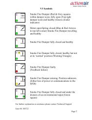
December 2009HotShield <strong>PTC</strong>HotShield <strong>PTC</strong> TMHigh Operating TemperatureSmoke Management and Fire DampersFeatures● Smoke Management and FireDampers operational up to300 °C for a period of 1 or 2hours (two versions available).● Thermally insulated electricControl Modes.● Pneumatic option available250 °C for one hour.● Halogen free low smoke andfume cabling supplied as astandard feature.● Low closed blade leakage.● Dampers when closed arecompliant to BS 476 Part 20Fire Damper Test Standard.● Actionpac Damper ControlSystem compatibility.● HotShield Vent <strong>PTC</strong> reverseaction dampers for HighOperating Temperature SmokeControl and Extractapplications.● HotShield Damper Interface(HDI) enclosure. Unique<strong>Actionair</strong> Interface heatprotection.Dampers Designed and Built in Britain
HotShield <strong>PTC</strong> TMApplication and WiringMode HM5 (24V System) and HM5 2HSupply On – Damper motors open.Supply Off – Spring closure.Cable specification:Si HF Low Smoke and Fume, HalogenFree, to IEC 754-1. Conforming to73/23/EEC directive.Release Time ≈ 22 secs.Reset Time ≈ 60 secs.(Connect 24V via a safety isolatingtransformer.)IP54 RatedAC/DC 24V50 1 / 60 Hz12.5 VA10/2 WImax8.3A @ 5ms–30...+50 CCONTINUOUSAC250V6(3)AM121234–+SUPPLY24V AC or DCVOLT FREE CONTACTCLOSED WHENDAMPER RELEASEDVOLT FREE CONTACTCLOSED WHENDAMPER RESETMode HM6 (230V System) and HM6 2HSupply On – Damper motors open.Supply Off – Spring closure.Cable specification:Si HF Low Smoke and Fume, HalogenFree, to IEC 754-1. Conforming to73/23/EEC directive.Release Time ≈ 22 secs.Reset Time ≈ 60 secs.(To isolate from main power supply, the system mustincorporate a device which disconnects the phaseconductors, with a least 3mm contact gap.)IP54 RatedAC 230V50 / 60 Hz14 VA12/4 W– 30...+50 CCONTINUOUSAC250V6(3)AMBLUEBROWNNL11234SUPPLY230V AC 50/60 HzVOLT FREE CONTACTCLOSED WHENDAMPER RELEASEDVOLT FREE CONTACTCLOSED WHENDAMPER RESETMultiple AssembliesLHDSTDRHDLHDSquare and rectangular casings areavailable in multiple modulearrangements, supplied complete withblanking strips for site assembly byothers. Additional support as well asprovision for thermal expansion(4mm/metre) should be allowed for onmultiple assemblies.STDRHDSTDRHDPLAN VIEWLHDLHDSTDRHDSTDRHDPLAN VIEWMultiple assemblies require installationapproval by the relevant local authority.STDRHDLHDSTDRHDApproximate Weights (kg)Square or Circular 100 150 200 250 300 350 400 450 500 550 600 650 70 750 850 850 900 950 1000Duct Size (mm)Series 2501 Square 3.4 3.4 3.4 4.2 4.8 5.6 6.5 7.4 8.6 9.6 10.8 12.4 13.6 14.9 16.2 17.7 19.2 20.8 23.5Series 2501 Square 6.2 6.2 6.2 7.4 8.7 10.3 11.9 13.2 14.6 16.3 18.5 20.5 22.1 24.0 25.9 28.1 30.3 32.4 34.5+ Installation FrameSeries 2601 Circular 5.3 5.3 5.3 6.1 7.2 8.4 9.6 11.2 12.6 14.0 15.9 17.5 19.1 20.7 22.5 24.3 26.2 29.3 32.1Series 2601 Circular 8.5 8.5 8.5 10.0 11.9 13.7 15.4 17.1 19.2 21.8 24.0 26.0 28.2 30.4 32.8 35.3 37.8 40.3 43.1+ Installation FrameControl Modes 5 and 6 7.6 Kg (including drive interface)4 www.actionair.co.uk
HotShield <strong>PTC</strong> TMHotShield Damper Interface Enclosure (HDI)Sectional View of HDI EnclosureHDI Enclosue LidSpecial ThermalInsulating MaterialHSFDI<strong>Actionair</strong> have developed a unique thermalenclosure to protect the Actionpac LNSrange of damper interfaces currentlyavailable.The enclosure consists of two separatematerials, enabling the HDI to function atthe extreme temperature specified. Theouter casing has endothermic propertiesthat significantly slow down the internaltemperature rise in a high temperatureemergency condition. The inner casing isa special thermal insulating material.The maximum temperature is 300°C forup to one hour. This has been tested andindependently witnessed by BRE (Ref TestNo. 221067A).The HDI enclosure is to be used inHotShield <strong>PTC</strong> applications where theActionpac LNS system is being used tocontrol the dampers.Dimensions20360 4 off 6mmdiameterholesSFDI UnitSFDIs and SDIs, can be installed withinthe HDI enclosure.The HDI can be mounted in any orientation,on a flat surface or alternative suitablemounting system.The SFDI, or SDI units are suppliedwithout the damper interface electronics,which will be supplied separately atcommissioning stage.Maximum normal external operatingtemperature: 30°C.Total Weight (including internal DIs) =11.5Kg (approx).396HDI EnclosueBaseTypical InstallationEndothermic ThermalInsulating Material1. Fix the 2 off mounting brackets provided,to the underside of the HDI enclosure, byscrewing into the threaded inserts withthe M5 screws provided.2. Allowing suitable cable access aroundthe HDI enclosure, position it in desiredlocation, and mark fixings positions usingthe bracket holes as a template.3. Remove HDI enclosure lid by unscrewingthe 6 off long screws/large flat washers4. Securely mount the HDI base in itsintended position. Hole specification andfixings by others.5. Remove DI/CMS lid.6. Connect cables and refit DI lid inaccordance with Actionpac catalogueinformation.MountingBracket7. Refit HDI enclosure lid with the 6 offscrews/large flat washers, taking care toposition cables in grooves. The insideinsulation is sufficiently soft to compresslocally around cables when the lid isscrewed down.3166 offM5 x 130mmscrews113Note: HDI lid may need to be removed andrefitted again during testing/commissioning.235384www.actionair.co.uk5
HotShield <strong>PTC</strong> TMInstallation SystemsPopular types of Installation Frame thatare available.DWFX TM (DRY WALL FIX) InstallationSystemTypically for installation into Dry Wall, StudPartitions.HEVAC / HVCA Galvanised SteelInstallation FramesTypically for installation into Blockwork,Concrete walls and floors.DWFX-F (Dry Wall FiX - Frame)DWFX-C (Dry Wall FiX - Cleat)DWFX-F Dimensional DataSee page 8 and 9.DWFX-C Dimensional Data50 50 50SpecificationThe <strong>Actionair</strong> DWFX-F installation methodis BRE assessed to BS476 Pt 20/22 for90 minutes (BRE assessment no.225283).The <strong>Actionair</strong> DWFX-F consists of a 1.2mm galvanised steel peripheral flangewith 50mm x 50mm x 3mm steel anglecleats with 14mm x 24mm oval slots,welded to damper casing for drop rodsupport.SpecificationThe <strong>Actionair</strong> DWFX-C consists of 50mmx 50mm x 3mm steel angle cleats with14mm x 24mm oval slots.Fully welded to damper casing for droprod support prior to wall construction.2414Comprehensive literature, outlininginstallation and features, is available for ourDWFX systems. Go to our website:-www.actionair.co.ukto view or download these as PDF files.6 www.actionair.co.uk
HotShield <strong>PTC</strong> TM 7HEVAC / HVCA Galvanised Steel Installation FramesGalvanised steel buildingties permit stablehandling, ease oftransport andconvenience of building into the surroundingstructure.Galvanised Steel Installation Frames(as required by HVC 6/5/83 Rev.1 July1999.)Installation frames are delivered to site as acomplete assembly with the appropriateDamper fitted therein. The frame shall beinstalled centrally in the thickness of abrick, blockwork or concrete surroundingwall or floor, or in the case of thick walls orfloors, so that the centre line of the frameis at least 50mm away from the nearestface of the wall or floor in which theassembly is mounted. The four tabs(building tie) forming each fixing pointshall provide a positive fixing into thestructure. Multiple assembly dampers upto 1500 x 1500 or 2000 x 1000 can befitted into fully assembled installationframes and delivered as one piece.Dampers in excess of these sizes will besupplied in sections with the installationframe supplied in kit-form, Drg AA/F/8057.This drawing and method statement will besupplied for assembly to on site.The maximum size of kit-form installationframes is 2500mm wide x 2000mm high.a. In brick or blockwork walls the tabs shallbe bent out and solidly built into the mortarjoints between the brick or blockwork.b. In the case of reinforced concrete wallsand floors, the tabs shall be bent out andtied with wire to the reinforcing bars whichwill be deliberately left protruding into theopening.The gap between the installation frameand builders work shall be backfilledwith mortar or concrete on both sidesof the flange.Adjacent frame assemblies must beseparated by builders work of a minimumthickness of 225mm (between installationframe upstand flanges) unless approvalhas been previously obtained from theappropriate Authority. For installationsbelow this dimension please refer to<strong>Actionair</strong> Sales office.In no case shall the HEVAC/HVCA frameand damper assembly be held in positionmerely by the adjacent ductwork, and itshould be noted that in reinforced concretestructures (especially floors), it will not besufficient to only backfill between thedamper installation frame and thesurrounding opening with mortar or fineaggregate concrete mix without provisionfor tying in the frame to the surroundingreinforced concrete structure.Approved InstallationsA binder containing approved installationillustrations is now available.Refer to <strong>Actionair</strong> Sales Office or visitour website, www.actionair.co.ukThe illustrations are under the headingPRODUCTS DRAWINGS.Although the included methods have beentested and assessed, it is recommend,that these, as with all installation methodsmust be confirmed with Building Control /Local Authority prior to manufacture.<strong>Actionair</strong> can also provide applications ofother proposed methods of installation,please contact our Sales Office to discussyour specific requirements.These again are the responsibility of theclient to ensure that these are acceptable toBuilding Control / Local Authority beforeconstruction commences.www.actionair.co.uk
HotShield <strong>PTC</strong> TMDamper Installation and Control Mode FittingThe <strong>Actionair</strong> unique snaplock driveinterface ensures user friendly, easy andsecure connection of the control mode tothe damper.The drive interface can be used up to wallthicknesses of 250mm. The driveinterface allows the control modes to befitted in any one of three orientations i.e.Vertically down, Position 1Horizontally, Position 2, (standard) orVertically up, Position 3.A “multi positions kit” is required forpositions 1 and 3 ( for position 2 the“multi positions kit”is optional).DAMPERDRIVESHROUDTRANSITPLATETHERMALENCLOSUREASSEMBLYEASY PULLLEVER KEYRINGTypical Installation1. Install the HotShield <strong>PTC</strong> Damper,complete with factory fitted damper shroudand transit plate, into the structure.2. Connect and fit ductwork to damperspigots.3. Remove transit plate and discard(recycle).4. Slide the snaplock drive interface intothe damper drive shroud. Pull the key ringon the easy pull lever, this snaplocks thedrive Interface into position.Care must be taken when back filling toensure that the snaplock retaining pinlocation hole and the entry slot of thedamper drive shroud is clear of builderswork debris.HDIChanging the Control Mode of theHotShield <strong>PTC</strong> to position 1 and 3on site:DAMPERSHROUDMOUNTINGFLANGESKEY RING ON THEEASY PULL LEVER1. Remove the 4 off M6 bolts andwashers, lift off the thermal enclosureassembly,2. Rotate the interface input shaft fullyanti-clock wise.3. Line up the output shaft slot on theunderside of the interface with the slot onthe interface plate.4. Locate the thermal enclosure assemblyto desired position and fix it to themounting flanges with M6 bolts andwashers.5. Fully close the damper.6. Pull the key ring on the easy pull lever,insert the interface assembly into thedamper shroud, line up its dotted line withthe end of the shroud, release the lever tolock.7. Refer to standard O+M for testing.INTERFACEINPUT SHAFTReverse MountingThe thermal enclosureand control mode canbe reverse mountedusing the “multipositions kit” onto theHotShield <strong>PTC</strong>M6 BOLTS +WASHERSTHERMALENCLOSUREASSEMBLYThe information contained herein is subject to changewithout notice due to continuing research anddevelopment.10 www.actionair.co.uk
HotShield <strong>PTC</strong> TMAcoustic DataThe data presented is from theLaboratory Determination of Acoustic andAerodynamic Performance of HotShield<strong>PTC</strong> High Operating TemperatureSmoke Management and Fire Dampers.A programme of extensive tests wascarried out in the Reverberation Chamberand North Transmission Chamber ofSound research Laboratories Limited,Holbrook Hall, Sudbury, Suffolk, generallyin accordance with BRITISH STANDARDSNos. 4196, 4773, 4856, 4857 and 4954.This independent test facility is approvedunder the NAMAS Scheme.From the selection of a duct velocitywithin the operational parameters of thedamper a resultant pressure drop fromTable 1 can be determined and the sumof these two components applied to theVelocity x Pressure Drop Vs Sound PowerLevel Graph. (Table 2)The graph is the result of a fullrange of acoustic tests on HotShield<strong>PTC</strong> High Operating TemperatureSmoke Management and Fire Damperswith the blades set in then fully openposition.The Spectrum Correction Data is appliedto the number obtained from the graphand a complete Sound Spectrum of FlowGenerated Noise for both Outlet (in duct)and Breakout (casing radiated) isobtained.Example:Duct with a design velocity of8 m/sec. HotShield <strong>PTC</strong> Damper Series2501 fully open.Pressure Drop = 22 Pa (Table 1).Multiply Velocity x Pressure Drop8 x 22 = 176.From Sound Power Graph (Table 2) plot176 on horizontal Velocity/Pressure axisagainst 2501 outlet (induct) graph toobtain 47 dBW on Vertical Sound PowerLevel Axis. Add or subtract corrections tothe 47 dBW to provide full spectrumanalysis.Velocity (m/s) X Pressure Drop (Pa) Vs Sound Power Level (dBW)90Pressure Drop Vs VelocityPRESSURE DROP (Pa)10090807060504030201098765432EXAMPLE LINETYPE 2501TYPE 260111 2 3 4 5 6 7 8 9 10 15Table 1VELOCITY (m/s)Damper LeakageHotShield <strong>PTC</strong> andHotShield Vent <strong>PTC</strong> closed bladeleakage as tested on a damper 1000mmwide x 1000mm high.Leakage Data at Ambient Temperature(Cold Smoke).15001SOUND POWER LEVEL (dBW)80706050403020EXAMPLE LINE2501 BREAKOUT2601 BREAKOUT2601 OUTLET (INDUCT)2501 OUTLET (INDUCT)PRESSURE DIFFERENTIAL ACROSS CLOSED DAMPER (Pa)10009008007006005004003002001009080706050403010200Table 21020304050607080901002003004005006007008009001000VELOCITY X PRESSURE DROP (m/s Pa)2000300040005000600070008000900010000105 6 7 8 9 10 20 30 40 60 80 10050 70 90Table 3LEAKAGE (I/s)HotShield <strong>PTC</strong> Outlet (Induct) SpectrumCorrectionsOctave Band63 125 250 500 1k 2k 4k 8kSeries 2501 +5 +4 +5 +5 +3 +1 -3 -5Series 2601 +9 +4 +4 +5 +3 +1 -3 -6HotShield <strong>PTC</strong> Breakout SpectrumCorrections63 125 250 500 1k 2k 4k 8k Hz+8 +11 +9 +6 -3 -6 -14 -17 dB+6 +10 +8 +4 -3 -3 -11 -14 dBThe leakage as detailed in Table 3 wasachieved after a total immersion test at300 °C for 1 hour (as witnessed by theLoss Prevention Council).12 www.actionair.co.uk
HotShield <strong>PTC</strong> TMSpecificationApprovalsHotShield <strong>PTC</strong> High OperatingTemperature Smoke Management andFire Dampers comprising of 75mmstainless steel aerodynamic interlockingblades incorporating synthetic seal, withstainless steel blade end bearings andperipheral gasketing. Housed in agalvanised fully welded, spigotted casingsuitable for square, rectangular, circular orflat oval connections.The totally enclosed precise movementopposed blade drive shall be positionedout of the airstream for protection againstdamage, be hard wearing and free running.The Control Mode/Damper connectionshall be by means of the snaplock driveinterface mechanism, which is totallyindependent of the ductwork.HotShield <strong>PTC</strong> High OperatingTemperature Smoke Management andFire Dampers in association with theirappropriate insulated control modes shallbe arranged for motor open and springclosed operation interfaced with a smokedetection/fire alarm system.HotShield <strong>PTC</strong> Damper and selectedthermally insulated Control Modes (HM5,HM5 2H, HM6 and HM6 2H) as suppliedby <strong>Actionair</strong>.HotShield Vent <strong>PTC</strong> High OperatingTemperature Smoke Control andExtract Dampers comprising of 75mmstainless steel aerodynamic bladesincorporating synthetic seal, with stainlesssteel blade end bearings and peripheralgasketing. Housed in a galvanised fullywelded, spigotted casing suitable forsquare, rectangular, circular or flat ovalconnections.The totally enclosed precise movementopposed blade drive shall be positionedout of the airstream for protection againstdamage, be hard wearing and free running.The Control Mode/Damper connectionshall be by means of the snaplock driveinterface mechanism, which is totallyindependent of the ductwork.HotShield Vent <strong>PTC</strong> High OperatingTemperature Smoke Control and ExtractDampers in association with theirappropriate insulated control modes shallbe arranged for motor close and springopen operation interfaced with a smokedetection/fire alarm system.HotShield Vent <strong>PTC</strong> Damper andselected thermally insulated ControlModes (HVM5. HM5 2H, HM6 and HVM62H) as supplied by <strong>Actionair</strong>ApprovalsHeat Degradation test witnessed by theLoss Prevention Council.Complies with the latest DW 144 casingleakage specification.HotShield <strong>PTC</strong> dampers, when closed,are compliant to BS 476 Part 20 FireDamper Test Standards.The insulated Control Modes satisfy therequirements of EN 50081-1 and EN50082-1 electro magnetic compatibility.Quality AssuranceCertification No.17Assessed to ISO 9001Customer Service<strong>Actionair</strong> provides quality productsbacked by a dedicated team committedto providing the very best in customerservice.Offering experienced technical backup,comprehensive sales and administrativecustomer support, productcommissioning and maintenance service.Ordering InformationExampleQuantity Series Accessories Duct Size Control Mode5 HS2501 IF 600(W) x 400(H) HM6 2HNumber ofunitsrequiredHS2501/<strong>PTC</strong>HotShield <strong>PTC</strong>Square or Rectangular(Motor Open/SpringClosure)HS2601/<strong>PTC</strong>HotShield <strong>PTC</strong>Circular(Motor Open/SpringClosure)HS2701/<strong>PTC</strong>HotShield <strong>PTC</strong>Flat Oval(Motor Open/SpringClosure)HSV3501/<strong>PTC</strong>HotShield Vent<strong>PTC</strong>Square or Rectangular(Motor Close/SpringOpening)HSV3601/<strong>PTC</strong>HotShield Vent<strong>PTC</strong>Circular(Motor Close/SpringOpening)HSV3701/<strong>PTC</strong>HotShield Vent<strong>PTC</strong>Flat Oval(Motor Close/SpringOpening)IFInstallation FrameDWFX-CDrywall Fix CleatDWFX-FDrywall Fix FlangeHDIEnclosureHSFDINominal DamperSpigot SizeHM5 <strong>PTC</strong>HM6 <strong>PTC</strong>HMV5 <strong>PTC</strong> VentHMV6 <strong>PTC</strong> VentHM5-2H <strong>PTC</strong>HM6-2H <strong>PTC</strong>HMV5-2H <strong>PTC</strong> VentHMV6-2H <strong>PTC</strong> VentHM5-3P <strong>PTC</strong>HMV5-3P <strong>PTC</strong> VentHM5-2P <strong>PTC</strong>HM6-2P <strong>PTC</strong>For full descriptive listof Control Modes see page 3www.actionair.co.uk13
HotShield <strong>PTC</strong> TMActionpac Damper Control SystemsElectro Mechanical SystemsActionpac EMS - Standard Control andMonitoring SystemControl and monitoring of Mode 5 orMode 6 damper actuators in groups of12, 24 or 36.Actionpac EMB - Bespoke Control andMonitoring System Control PanelThe EMB Control Panels typically consistsof the appropriate number of switches toprovide individual or group control, LEDindication for status monitoring and allnecessary relays and timers to complywith the customer needs for fully or semiautomatic damper operation. The EMBpanels are purposely manufactured forany particular project to suit specific clientrequirements.Addressable SystemsActionpac 60/120 ( LNS Standard)Intelligent Damper Control andMonitoring SystemActionpac 60 for the control/monitoringof up to 60 off Hot/SmokeShield dampers.Actionpac 120 for the control/monitoringof up to 120 off Hot/SmokeShielddampers.Actionpac LNS3 Intelligent DamperControl and Monitoring SystemThe Actionpac LNS3 system represents anew generation of smoke/fire dampercontrol. The system has been designedwith the user in mind, providing anadvanced tool that simplifies installationand commissioning of smoke/firedampers and peripheral devices. ThePanel PC operates on a Windowsplatform making it universally acceptedand utilises solid state technology foroptimum reliability.It’s server architecture delivers newbenefits such as reduced commissioningtime, simplified operation and scope forfuture growth.The Actionpac LNS3 system is designedto protect life and property from damagecaused by smoke and fire, by providingthe means to:–• Compartmentalise fire zones.• Reduce the spread of smoke and fire.• Keep escape routes and fire-fightingaccess open.• Allow pressurisation and smoke extractby combined operation of dampersand fans.Benefits• Completely flexible to meet practicallyany building’s damper requirements• Three levels of alarm priority• Panel PC driven system with real-timegraphic displays• Panel PC utilises solid state technologyfor optimum reliability• Full configuration and diagnostics fromPanel PC• Optional automatic scheduled Dampertesting• Multiple wiring configurations to includeRadial or Loop Topology• Damper operational count provided• Flexibility to accommodate any lastminute changes to strategy, zones,damper quantities, references anddescriptions etc.• Powerful and flexible functionalityenables standardisation of software (nobespoke site specific versions required)• Cause and effect scenarios easilyaccommodated• Multiple options for monitoringdampers, individually or by group orzone - output contacts can betriggered when a predefinedpercentage within a group or zonechange position• System designed to cater forenvironmental occupancy as well asthe building’s smoke/fire strategy.RS232 BMS link provided enabling aBMS to link directly to the system toread damper positions etc.• Optional remote access available• Graphical User Interface displays livedamper status and details as well ascause and effect strategies• Text fields facilitate clear description ofdevice references and locations• System wide activity logged andviewable for diagnostics andmaintenance• Allows for phased commissioning andfuture expansion• CE marked, LVD and EMC compliantActionpac LNS3 Intelligent DamperControl and Monitoring SystemFully comprehensive brochures are available on all Actionpac products. Visit the<strong>Actionair</strong> website w.w.w.actionair.co.uk and download the relevant pdf.14 www.actionair.co.uk
HotShield <strong>PTC</strong> TMGeneral Schematic of Actionpac LNS3 Damper Control SystemTo additionaldevices as requiredTo additionaldevices as required24/230 volt(local powerby others)SFDISFDISmoke Fire Damper InterfaceOne per Control ModeSFDI24/230 volt(local powerby others)Damper Control Mode*24/230 volt(local powerby others)SFDINDI404Network Digital Input / OutputDevice - provides fourinputs and four outputs*Only one Damper to be controlled byan SFDI, SDI or FDI please refer to<strong>Actionair</strong> Sales Office.Supply to each Damper Interface fromnearest local distribution board.SFDI24/230 volt(local powerby others)24/230 volt(local powerby others)SFDISFDI24/230 volt(local powerby others)SFDI24/230 volt(local powerby others)NDI40424/230 volt(local powerby others)Data NetworkPanel PCVent PanelB.M.S.OUTPUTSINPUTSFire Alarm InputsBMS InputsFireman’s Switch Inputswww.actionair.co.uk15
HotShield <strong>PTC</strong>Ruskin Air Management Limitedis a ISO 9001 and 14001 registeredcompany.The statements made in this brochure or by ourrepresentatives in consequence of any enquiriesarising out of this document are given for informationpurposes only. They are not intended to have anylegal effect and the company is not to be regardedas bound thereby. The company will only acceptobligations which are expressly negotiated for andagreed and incorporated into a written agreementmade with its customers.Due to a policy of continuous product developmentthe specification and details contained herein aresubject to alteration without prior notice.Comprehensive and detailed informationis available for all <strong>Actionair</strong> products.Visit our website at www.actionair.co.ukRuskin Air Management LimitedSouth Street, Whitstable, KentCT5 3DU England.Tel: 01227 276100Fax: 01227 264262Email: sales@actionair.co.ukWebsite: www.actionair.co.ukBROCHURE PRODUCTION www.geoffstrange.co.uk LNNN00122