OPERATIONS & MAINTENANCE MANUAL - McCormick PCS Info
OPERATIONS & MAINTENANCE MANUAL - McCormick PCS Info
OPERATIONS & MAINTENANCE MANUAL - McCormick PCS Info

You also want an ePaper? Increase the reach of your titles
YUMPU automatically turns print PDFs into web optimized ePapers that Google loves.
C • 1/Page 6 of 11<strong>OPERATIONS</strong> & <strong>MAINTENANCE</strong> <strong>MANUAL</strong>Operating StandardsNo. C • 1Start-Up4. Maintaining current and historical preventive maintenance records.5. Reviewing energy management information and appropriate action to minimizeenergy consumption.6. Preparing monthly tenant request summary reports.I. Organization and PersonnelThe Chief Engineer in conjunction with the Manager is responsible for, but not limited to:1. Ensuring all engineering personnel adhere to policies and operating procedures.2. Maintaining current position description for all engineering department positions.3. Assisting in the preparation and maintenance of approved staffing tables.4. Participating in the hiring of subordinate personnel under the guidelines of theCompany.5. Developing in-house training and educational programs for all engineeringpersonnel.6. Assisting in the preparation and/or recommendation of all action plans, evaluations,and salary administration for engineering personnel.7. Monitoring and implementing OSHA requirements for assigned property.J. Physical Facilities ManagementThe Chief Engineer in conjunction with the Assistant Chief Engineer, if applicable, isresponsible for, but not limited to:1. Managing and maintaining all facility equipment.2. Understanding of the property’s security systems in conjunction with the buildingoperations.© 1992 - 1997, Michael Robert <strong>McCormick</strong>All Rights Reserved
C • 1/Page 7 of 11<strong>OPERATIONS</strong> & <strong>MAINTENANCE</strong> <strong>MANUAL</strong>Operating StandardsNo. C • 1Start-Up3. Coordinating and implementing the energy management programs.4. Establishing and implementing an effective preventive maintenance program.5. Implementing the fire and emergency procedures for all engineering staff.6. Ensuring that all emergency equipment is in good working order and in compliancewith all local codes.7. Conducting regular inspections to ensure maximum quality and consistency withinthe total property.K. Miscellaneous ResponsibilitiesThe Chief Engineer is responsible for, but not limited to:1. Reporting to work on time and ready to work.2. Dressing for work in appropriate attire which should be neat in appearance (pressed)with prior approval by the Company.3. Checking with Manager each day for any building events duties scheduled for thatday or incidents to be reported.4. Reporting any events which transpired the day before or during the weekend duty tothe Manager, along with an Incident Report, the following day. For emergencies ofany type, contact the Manager right away. No problem is too small; if you are notsure, call.5. Reporting incidents of any type -- mechanical, tenant, auto, or personal -- thatinvolve the building to the Manager.6. Reporting any personal difficulties or conflicts with each other or any nonengineeringperson to the Manager.7. Attending scheduled staff meetings called by the Company or Manager.© 1992 - 1997, Michael Robert <strong>McCormick</strong>All Rights Reserved
C • 1/Page 8 of 11<strong>OPERATIONS</strong> & <strong>MAINTENANCE</strong> <strong>MANUAL</strong>Operating StandardsNo. C • 1Start-Up8. Maintaining departmental records in accordance with established guidelines.9. Maintaining good working relationships will all tenants, responding to tenantcomplaints/requests in a timely and professional manner.10. Maintaining effective employee communication and good work relationships.11. Assuming additional responsibilities as delegated by the Company.L. Building InspectionsThe Chief Engineer in conjunction with the Assistant Chief Engineer, if applicable, isresponsible for attending and conducting, on a timely and recurring basis, propertyinspections as scheduled but is not limited to the following areas:1. ScopeDaily Work Routinesa. Tour all physical facilities.b. Review of preventive maintenance program.c. Review of energy conservation programs.d. HVAC equipment performance testing.e. Review of water treatment programs.f. Review of engineering manpower levels.g. Base building and tenant construction.h. General building maintenance.i. Provide conclusions and recommendations.The Chief Engineer will be responsible for, but not limited to, developing Daily Work Routineprocedures for each engineering personnel and work shift. Routines should include Start-upEngineer, Day Engineer, Shut-down Engineer and Saturday Engineer, as shown in the followingexamples:© 1992 - 1997, Michael Robert <strong>McCormick</strong>All Rights Reserved
C • 1/Page 9 of 11<strong>OPERATIONS</strong> & <strong>MAINTENANCE</strong> <strong>MANUAL</strong>Operating StandardsNo. C • 1Start-UpDaily Work Routine ExampleSchedule: 0600-14000600-0800DAILY ROUTINE WORK PROCEDURESSTART UP ENGINEERBuilding AA. Dressed in uniform.B. Check fire alarm panel and dry pipe room for proper operation and log in.C. Start chillers and related equipment.D. Check cooling tower for proper operation.E. Take make up water meter reading.F. Turn 7th and 8th floor convector units on.G. Check air compressor level.H. Conduct water treatment test on Mondays.0800-1400Building BA. Check roof top HVAC system for proper operation.B. Check temperature setting on conference room unit, check fan for “ON” positionand temperature setting at 72.C. Check the fire alarm panel and dry pipe room.D. Check air compressor oil level.E. Check the operation of the D.S.C. panel for any alarms.F. Take readings and adjust the temperature as necessary.A. Check with the Engineering Supervisor for further instructions.B. Review previous day’s work assignment (if not complete, reassign.)© 1992 - 1997, Michael Robert <strong>McCormick</strong>All Rights Reserved
C • 1/Page 10 of 11<strong>OPERATIONS</strong> & <strong>MAINTENANCE</strong> <strong>MANUAL</strong>Operating StandardsNo. C • 1Start-UpWEEKLY:C. Help with work tickets as necessary.A. Check all air handlers for proper operation.B. Check sump pumps every Saturday.Schedule: 1200-20001200-13001300-180017001800-2000DAILY ROUTINE WORK PROCEDURESSHUT DOWN ENGINEERA. Dressed in uniform and report to the Assistant Engineering Supervisor forinstructions.B. Make rounds of Chiller Plant and take readings.C. Check the cooling tower for proper and continued operation.D. Check Building B HVAC system, take readings and make adjustments totemperature and static pressure as necessary.E. Check with Property Management Secretary (Building B) for any work tickets.F. Conduct water treatment on Friday.A. Proceed with work tickets or preventive maintenance assignments.A. Check with Property Management (Building B) for any work tickets.A. Check fire alarm panels at Building B and log in.B. Set Building B temperature set point up to 57 in Spring/Fall, 51 in Summer and 68in Winter, or as needed.C. Set Building B main conference room thermostat at 75.© 1992 - 1997, Michael Robert <strong>McCormick</strong>All Rights Reserved
C • 1/Page 11 of 11<strong>OPERATIONS</strong> & <strong>MAINTENANCE</strong> <strong>MANUAL</strong>Operating StandardsNo. C • 1Start-UpD. Check Building A domestic water, and sewage ejector pumps.E. Check Building A fire alarm panels and log in.F. Check the air compressors for proper operation.G. Secure the chiller(s) and related equipment.H. Place all complete and incomplete work tickets on the Assistant EngineeringSupervisor’s desk for review the next day.Each day the work routine should include the following:A. The readings on the HVAC system at Building B are mandatory for all Engineers.B. All Engineers will be required to familiarize themselves with this daily routine workprocedure.© 1992 - 1997, Michael Robert <strong>McCormick</strong>All Rights Reserved
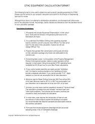
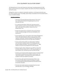
<strong>MAINTENANCE</strong> MANAGEMENT<strong>OPERATIONS</strong> & <strong>MAINTENANCE</strong> <strong>MANUAL</strong>C • 2/Page 1 of 8No. C • 2Overtime HVACThe intent of this section is to be familiar with the program and operating costs associated withOTAC equipment calculation format, that the Manager conducts for each project. Thiscomputerized program is not available for use but the Manager is available to demonstrate theprogram and how the final cost values are determined.OTAC FormatThe following format was used to determine each project’s operating expenses for OTAC.Although this is done in an attempt to standardize calculations, not all projects will utilize everypart of the calculation format. Accordingly, clearly indicate any deviations from the standardformat on your calculation package, and forward comments to the Manager.Calculation Guidelines1. All projects will include (Equipment Depreciation) in their calculations. Verifywith the Manager for the Estimated Life Factor.2. It is understood that Water Chilling Units operating at partial load for overtime usewill consume more KW per Ton than at full load. For the sake of this calculation,however, we will use (designated KW per Ton).3. Projects that operate their central plant continuously will show on their calculationpackage only those costs attributed to the overtime use.4. Concerning labor costs, it is the position of the Company that engineering laborrelative to plant operation will be required in most cases. Use the projectedoperating hours multiplied by $15.00 per hour for your manpower calculations.5. If your control system specifics can easily provide “ventilation only” (no heat/nocooling-circulation of air handling unit only), provide a separate calculation. If youcannot provide “V.O.”, begin research on how we can accomplish this for laterdiscussion.6. Minimum load for Water Chilling Units over 300 Tons will be 30% of full load.Minimum load for WCUs 300 Tons and smaller is at your discretion, but is assumednot to be over 30% of full load.© 1992 - 1997, Michael Robert <strong>McCormick</strong>All Rights Reserved
<strong>MAINTENANCE</strong> MANAGEMENT<strong>OPERATIONS</strong> & <strong>MAINTENANCE</strong> <strong>MANUAL</strong>C • 2/Page 2 of 8No. C • 2Overtime HVAC7. At times, you may have overtime requests in excess of “minimum load.” Thecalculation considers this and includes “minimum load” and “other loadconditions.” The formulas are the same, and they are included to clarify andsimplify the calculation.8. In most cities, code requires the introduction of fresh air and the removal of toiletexhaust anytime the building is occupied. It is recommended that these be operatedand associated costs be the overtime calculation.9. Formulas that include equipment amperage should use actual operating amps in lieuof nameplate amperage.10. Relative to the chilled water/condenser water pump calculation, it is understood thatelectrical consumption for the chilled water pump will change with the number ofAHUs operating. For this calculation, however, we will use the operating amperageof both pumps at the minimum load condition, as the difference would benegligible.11. In regard to cooling water fan electrical calculation, an assumption of 50% run timeof one fan may be used. Feel free to calculate using actual conditions if theseconditions can be verified.12. Air compressor run time percentage is assumed to be 33% for all projects. At 100%occupancy verify actual run-time to estimate.13. On equipment depreciation, industry standards recommend using 30 years forestimated equipment life and $785.00/ton of plant capacity for equipment cost. Ifyou can identify actual cost, please do so.14. Relative to the equipment maintenance calculation, total the project budget amountsfor account (#) - Filters, Water treatment, and HVAC Supplies for use in your totalmaintenance costs.15. When calculating the AHU electrical consumption of Variable Air Volume systems,use actual operating amperage of the AHU at least two hours after start-up.16. It is the intent of the 20% overhead to recover the costs of relative to overtimeheating. You may adjust the number to reflect actual costs incurred.© 1992 - 1997, Michael Robert <strong>McCormick</strong>All Rights Reserved
<strong>MAINTENANCE</strong> MANAGEMENT<strong>OPERATIONS</strong> & <strong>MAINTENANCE</strong> <strong>MANUAL</strong>C • 2/Page 3 of 8No. C • 2Overtime HVACThis calculation has been structured to assure fair and equitable billing of overtime HVAC in thoseinstance where numerous tenants request overtime HVAC. On the following work sheets enteryour cost values only in the “green cells,” or unprotected cells where information values arerequired.The following data will be required to conduct the OTAC calculations:1. Project Name 15. Cooling Tower Run-time2. Chiller Unit 16. O.A. & T.E. Fan Amperage3. Chiller Tonnage Capacity 17. Air Compressor Amperage4. Chiller Design KW per Ton 18. Air Compressor Run-time5. Min. Load # AHUs & VAV Boxes 19. Equipment Cost for Plant6. Average Amperage per AHU 20. Equipment Estimated Life7. Building Average Voltage 21. Annual Run-time8. Average Cost per KW 22. Maintenance Cost:9. # Condenser Pumps a. Air filters10. Total Condenser GPM Rate b. Water treatment11. Cycles of Concentration c. HVAC Supplies12. Chill water pump Amperage d. Misc. Supplies13. Condenser pump Amperage e. Man-power14. Cooling Tower Amperage 23. Water & Sewage Cost© 1992 - 1997, Michael Robert <strong>McCormick</strong>All Rights Reserved
<strong>MAINTENANCE</strong> MANAGEMENT<strong>OPERATIONS</strong> & <strong>MAINTENANCE</strong> <strong>MANUAL</strong>C • 2/Page 4 of 8No. C • 2Overtime HVACCalculation ExampleStep One -- Electrical CostsA. Water Chilling Unit(1) Condition #1 -- Minimum Load (4 AHUs):Design KW per Ton x minimum load = Total Ch.71 x 30% of 300 Tons = Total Chiller KW at condition #1.71 x 90 = 63.90 KW(2) Condition #2 -- Other Load (5 AHUs):Design KW per Ton x load = Total Chiller KW at condition #2.71 x (min. load in tons : number of AHUs run at min. load)x 5 = Total Chiller KW at condition #2.71 x (90 : 4) x 5 = 79.9 KW at condition #2(3) Condition #3 -- Other Load (6 AHUs):Design KW per Ton x load = Total Chiller KW at condition #3.71 x (min. load in tons: number of AHUs run at min. load)x 6 = Total Chiller KW at condition #3.71 x (90 : 4) x 6 = 95.85% KW at condition #3NOTE: Carry out the calculation to the extent necessary.© 1992 - 1997, Michael Robert <strong>McCormick</strong>All Rights Reserved
<strong>MAINTENANCE</strong> MANAGEMENT<strong>OPERATIONS</strong> & <strong>MAINTENANCE</strong> <strong>MANUAL</strong>C • 2/Page 5 of 8No. C • 2Overtime HVACB. Air Handling Units:(1) Condition #1 - Minimum Load (4 AHUs):No. of AHUs x Volts x Amps x square foot of phase ¸ 1000= Total AHU KW at condition #14 x 480 x 14 x 1.732 : 1000 = 46.6 KW(2) Condition #2 -- Other Load (5 AHUs):Use same formula and carry out as with the Water Chilling Unit calculation.C. Chiller Water and Condenser Water PumpsVolts x (Amps/CWP + Amps/CHWP) x 1.732 : 1000= Total Pump KW at all conditions480 x (35 + 30) x 1.732 : 1000 = 54 KWD. Cooling Tower FanVolts x Amps x 1.732 x % run time : 1000= C.T. KW at all conditions480 x 52 x 1.732 x .5 (50%) : 1000 = 21.6 KWE. Outside Air and Toilet Exhaust FansVolts x (Amps/T.E. + Amps/O.A.) x 1.732 : 1000= Total Fan KW at all conditions480 x (14 + 18) x 1.732 : 1000 = 26.6 KWF. Air CompressorVolts x Amps x 1.732 x .15(15%) : 1000= Total Air Compressor KW at allconditions480 x 10 x 1.732 x .15(15%) : 1000 = 1.3 KWG. Total Electrical Costs© 1992 - 1997, Michael Robert <strong>McCormick</strong>All Rights Reserved
<strong>MAINTENANCE</strong> MANAGEMENT<strong>OPERATIONS</strong> & <strong>MAINTENANCE</strong> <strong>MANUAL</strong>C • 2/Page 6 of 8No. C • 2Overtime HVAC(1) Condition #1 -- Minimum Load (4 AHUs):Water Chilling Unit -- 63.9 KWAir Handling Units -- 46.6 KWChilled/Condenser Pumps -- 54.0 KWCooling Tower Fan -- 21.6 KWOutside Air/Toilet Exhaust -- 26.6 KWTotal KW Condition #1 -- 214 KW(2) Condition #2 -- Other Load (5 AHUs):Carry out the totalization for however many “conditions” you used in the waterchilling unit and air handling unit calculations.Step Two -- Water CostsThe evaporation rate is generally 1% of the total condenser water GPM flow less 4 cycles ofconcentration. The District of Columbia Water and Sewer charge equals $2.86 per 100 cu.ft. or 750 gallons. One cubic foot of water equals 7.5 gallons.The unit cost per gallon is based on $2.86 : 750 gallons equated to $.0038.A. Condition #1 -- Minimum Load 90 Tons (4 AHUs):Evaporation Rate = 1% of GPM rateNumber of Pumps: 1Total Pump GPM Rate: 900Bleed Cycles = (Egpm/C-1) 4 cyclesTotal Make-up = Rate + CyclesHourly Evaporation rate = E rate x 60 min.Number 1 Load Tonnage x Hourly E rate = Make-up rateMake-up Rate x $.0038= .30% Ton= 900 PGPM= 9 1% Rt= 3 CGPM= 12 TMup= 720 HMup= 216 LMup=$0.82 PrhrB. Condition #2 -- Other Load (5 AHUs):© 1992 - 1997, Michael Robert <strong>McCormick</strong>All Rights Reserved
<strong>MAINTENANCE</strong> MANAGEMENT<strong>OPERATIONS</strong> & <strong>MAINTENANCE</strong> <strong>MANUAL</strong>C • 2/Page 7 of 8No. C • 2Overtime HVACEvaporation Rate = 1% of GPM rateNumber of Pumps: 1Total Pump GPM Rate: 900Bleed Cycles = (Egpm/C-1) 4 cyclesTotal Make-up = Rate + CyclesHourly Evaporation rate = E rate x 60 min.Number 1 Load Tonnage x Hourly E rate = Make-up rateMake-up Rate x $.0038= .35% Ton= 900 PGPM= 9 1% Rt= 3 CGPM= 12 TMup= 720 HMup= 252 LMup=$0.96 PrhrStep Three -- Equipment DepreciationEquipment CostEstimated Life x Annual Run Time= Depreciation Cost$475,000 = $4.3530 x 3,640Step Four -- Equipment Maintenance CostMaintenance Costs: annual operating hours = Equipment Maintenance Costs$12,550 : 3,640 = $3.45Step Five -- Totals CalculationA. Condition #1 -- Minimum Load (4 AHUs):1. Total Electrical Costs -- Condition #1 -- 214 KW x $.065 = $13.912. Total Water Costs -- Condition #1 -- 216 x $.0038 = $.823. Equipment Depreciation = $4.354. Equipment Maintenance = $3.45Subtotal Hourly Cost --Condition #1 $22.53© 1992 - 1997, Michael Robert <strong>McCormick</strong>All Rights Reserved
<strong>MAINTENANCE</strong> MANAGEMENT<strong>OPERATIONS</strong> & <strong>MAINTENANCE</strong> <strong>MANUAL</strong>C • 2/Page 8 of 8No. C • 2Overtime HVACOverhead = + 20% 4.50Total$27.03 /hrB. Conditions #2 -- Other Load (5 AHUs):Carry out the totals calculations for however many “conditions” you used in the waterchilling unit, air handling unit and water cost calculations.© 1992 - 1997, Michael Robert <strong>McCormick</strong>All Rights Reserved
<strong>MAINTENANCE</strong> MANAGEMENT<strong>OPERATIONS</strong> & <strong>MAINTENANCE</strong> <strong>MANUAL</strong>C • 3/Page 1 of 2No. C • 3Meter ReadingsThe Chief Engineer will be responsible for conducting monthly meter readings for all electricalsubmeters for tenant and base building usage.For those projects not required to billback the tenant for submetering, refer to the Manager forclarification, the Chief Engineer will be required to maintain meter readings for audit purposes.Monthly ReadingsPrior to conducting meter readings make sure all meters are identified. For example: electric meteron the 3rd floor located in the electric closet for XYZ Tenant would read:XYZ - 3rd.FL.Ele.Cl.Or a code system can also be set up using a meter log; Meter 1A-3rd. West, etc.The Chief Engineer will be responsible for training all engineers on how to properly read metersand log entries.Meter Reading InstructionsThe Monthly Tenant Meter Reading form (refer to No. H, “Sample Forms”, Form C3-1) must beused when conducting meter readings.Read all tenant meters on the last Friday of each month.1. For Line 1, enter meter reading for present month.2. For Line 2, enter meter reading for the past month.3. For Line 3, subtract Line 2 from Line 1.4. For Line 4, combine total of all #3 lines.5. For Line 5, enter the monthly KWH Cost.6. For Line 6, enter the annual tenant meter total.7. For Line 7, add all #6 lines.8. For Line 8, enter the combined average KWH Cost of Line 5.© 1992 - 1997, Michael Robert <strong>McCormick</strong>All Rights Reserved
<strong>MAINTENANCE</strong> MANAGEMENT<strong>OPERATIONS</strong> & <strong>MAINTENANCE</strong> <strong>MANUAL</strong>C • 3/Page 2 of 2No. C • 3Meter ReadingsMonthly BillbackAfter taking each month’s meter readings, transfer the readings onto the computerized program(refer to No. H, “Sample Forms,” Form C3-2) and follow the instructions in the program. Refer allquestions or problems to the Manager when using the program diskette.© 1992 - 1997, Michael Robert <strong>McCormick</strong>All Rights Reserved
<strong>MAINTENANCE</strong> MANAGEMENT<strong>OPERATIONS</strong> & <strong>MAINTENANCE</strong> <strong>MANUAL</strong>C • 4/Page 1 of 1No. C • 4Water Chilling Unit Readings (Logs)Operating logs shall be maintained whenever operating personnel are on duty and available torecord the readings. Recommended log interval is one hour, with three hours being the maximum.Operating logs shall include, as a minimum, the following information:1. Condenser pressure2. Condensing temperature3. Condenser water supply and return temperature4. Chilled water supply and return temperatures5. Liquid refrigerant temperature6. Evaporator pressure7. Amps8. Oil level9. Oil temperature10. Oil pressure.Use of the water chilling unit manufacturer’s standard log sheets are discouraged. Custom designedlog format is recommended so that other applicable readings (flows, BTU meter readings, by-passor back-flow volumes, etc.) may be recorded. (Refer to No. H, “Sample Forms,” C-4, Chiller Log.)© 1992 - 1997, Michael Robert <strong>McCormick</strong>All Rights Reserved
<strong>MAINTENANCE</strong> MANAGEMENT<strong>OPERATIONS</strong> & <strong>MAINTENANCE</strong> <strong>MANUAL</strong>C • 5/Page 3 of 4No. C • 5Tenant Construction ProceduresNo core drilling on concrete slab cutting shall occur during normal business hours.Contractor shall pay for an engineer to be available on overtime to oversee this type ofactivity. The Management Office reserves the right to determine what construction work isconsidered inappropriate for normal business hours.General contractors must notify the Management Office of all after hours constructionactivity. A list of all after hours workers must be turned in by 3:00 P.M. for weekday work,at 11:00 A.M. Thursday for weekend work..All construction workers arriving after hours Monday through Friday and all day Saturday,Sunday and Building Holidays must sign in at the security desk. Any worker whose namehas not been included on the list will not be admitted unless vouched for by a constructionsuperintendent. All workers must wear name tags identifying themselves and the companythat they work for whenever they are on the project.All work which requires the assistance of a building engineer will be arranged through theManagement Office with 24 hours’ advance notice. This type of work would includesprinkler work/fire pump shut down, fire alarm work, electric tie in’s or short downs,plumbing riser shut downs, HVAC tie in’s or shut downs. A request form has been attachedto this document.Contractors can check out keys for the mechanical and electrical room through theManagement Office. A valid license must be left as a deposit to borrow this key.11. Worker ConductAbusive language or actions on the part of the workers will not be tolerated. It will be theresponsibility of the General Contractor to enforce this regulation on a day- to-day basis.12. Posting of Rules and RegulationsA copy of these rules and regulations, acknowledged and accepted by the GeneralContractor, must be posted on the job site in a manner allowing easy access by all workers.It is the General Contractor’s responsibility to instruct all workers including subcontractorsto familiarize themselves with these rules.13. Construction Inspections© 1992 - 1997, Michael Robert <strong>McCormick</strong>All Rights Reserved
<strong>MAINTENANCE</strong> MANAGEMENT<strong>OPERATIONS</strong> & <strong>MAINTENANCE</strong> <strong>MANUAL</strong>C • 5/Page 4 of 4No. C • 5Tenant Construction ProceduresContractor is to do a thorough inspection of all common areas prior to construction todocument any existing building deficiencies. Upon completion of work, contractor shallreturn these areas to the same condition in which they were originally viewed. Anydamages caused by the contractor shall be corrected at the sole cost of the contractor.14. SignageContractor or subcontractor signage may not be displayed in the building common areas orany of the window glass.15. ParkingThe loading dock will be used for loading and unloading. All contractors can makearrangements with the garage operator for daily parking. Any parking in rear of the buildingthat is not authorized by the Manager will be subject to ticketing and towing.© 1992 - 1997, Michael Robert <strong>McCormick</strong>All Rights Reserved
<strong>MAINTENANCE</strong> MANAGEMENT<strong>OPERATIONS</strong> & <strong>MAINTENANCE</strong> <strong>MANUAL</strong>C • 6/Page 1 of 5No. C • 6Outside AirThe Chief Engineer will be responsible for maintaining at all times the necessary amount of outsidemake-up to the HVAC system, as required by local jurisdiction codes and/or ASHRAE standards.Equipment Room VentilationVolume requirements for mechanical equipment rooms are covered in ASHRAE Standard 15. Thestandard splits ventilation air requirements into two categories - natural and mechanical ventilation- based on the location of the equipment.When a refrigeration system is located outdoors more than 20 feet from any building opening and isenclosed by a penthouse, lean-to or other structure, natural ventilation will be used.The structure must not be connected to any occupied building by any means including: doorways,pipe tunnels or electrical conduit raceways, ventilation or ductwork.The free-aperture cross section for ventilating the machinery room should amount to at least:F = G 0.5where,F =G =the free opening area in square feet.the mass of refrigerant in pounds in the largest system, and part which is located in themachinery room.Most mechanical equipment room designs do not permit the use of natural ventilation. When therefrigeration system does not meet the requirements just described for a natural ventilation system,mechanical ventilation must be provided. According to ASHRAE Standard 15:The minimum mechanical ventilation required to exhaust a potential accumulationof refrigerant due to leaks or a rupture of the system shall be capable of removingair from the machinery room in the following quantity:Q = 100 x G 0.5© 1992 - 1997, Michael Robert <strong>McCormick</strong>All Rights Reserved
<strong>MAINTENANCE</strong> MANAGEMENT<strong>OPERATIONS</strong> & <strong>MAINTENANCE</strong> <strong>MANUAL</strong>C • 6/Page 2 of 5No. C • 6Outside Airwhere,Q =G =the airflow in cubic feet per minute.the mass of refrigerant in pounds in the largest system, any part of which islocated in the machinery room.“Q” represents the minimum airflow that the ventilation system must be capable of providing whilethe equipment room is purged of refrigerants. According to Standard 15, it is not necessary to runthe ventilation at this volume continuously, provided that:...a sufficient part of the mechanical ventilation shall be operated to provide normalvolumes equal to the larger of the following:a) 0.5 cfm per square foot of machinery room area; andb) operable if necessary for operator comfort, at a volume required to maintaina maximum temperature rise of 18° F based on all of the heat-producingmachinery in the room.Thus, two distinct ventilation rates are defined for the mechanical equipment room. The first iscontinuous ventilation at a rate of 0.5 cfm per square foot (or more if excessive heat is produced inthe room), and the second is the purge rate (based on mass of refrigerant in the refrigerationsystem). The standard can be met by providing continuous ventilation at the higher of these tworates; however, when the purge rate is significantly higher than the continuous ventilation rate, itmay be desirable to use a fan system capable of operating at two distinct rates.Multiple fans, multiple-speed fans or other modulation devices may be used if a two-tieredventilation system is used. When the ventilation system is run at reduced airflow for continuousventilation, controls must be provided to increase the ventilation rate to the purge rate (Q) whennecessary. Automatic purge of the equipment room can be accomplished by linking the alarmoutput of a refrigerant (or oxygen) monitor into the ventilation system. When automatic purge isnot employed, a switch to initiate purge ventilation should be located outside the main entrance tothe mechanical equipment room (M.E.R.).Sick Building Syndrome© 1992 - 1997, Michael Robert <strong>McCormick</strong>All Rights Reserved
<strong>MAINTENANCE</strong> MANAGEMENT<strong>OPERATIONS</strong> & <strong>MAINTENANCE</strong> <strong>MANUAL</strong>C • 6/Page 3 of 5No. C • 6Outside AirAccording to the National Institute of Occupational Safety and Health (NIOSH), employeessuffering from poor air quality complain about one or more of the following: eye irritation; drythroat; headache; fatigue; sinus congestion; skin irritation; shortness of breath; cough;dizziness; nausea; sneezing; and nose irritation. Usually these symptoms disappear afteremployees leave the workplace.Most experts believe the likely causes of this so-called “sick building syndrome” are energyconservation measures compounded by poorly designed or maintained heating, ventilating and airconditioning(HVAC) systems -- both of which help to trap contaminants indoors. But thephysiological mechanism that produces symptoms remains a mystery.When indoor air pollution sickens workers, testing of air samples may reveal concentrations of oneof more that 600 specific air contaminants that are regulated by OSHA. The chemicals may be atlevels known to cause illnesses. Consequently, the employer will take steps to bring the exposureto permissible levels.However, in “sick” buildings, air sampling reveals the presence of hundreds of chemicals, butusually no one pollutant even begins to approach levels considered unsafe. Scientists suspect thatthis chemical soup composed of many pollutants is at the root of sick building syndrome.PreventionWhat can you do about ventilation-related problems? Maintain your HVAC system on a regularbasis and boost the volume of fresh outdoor air that comes into your facility.• Maintaining Your HVAC SystemHeating, ventilating and air-conditioning (HVAC) systems can be the source of air qualityproblems when they are poorly designed or improperly operated and maintained. Forinstance, water collecting in a poorly designed or maintained system can become a breedingground for biological contaminants, such as mold spores, bacteria or viruses. The HVACsystem may then disseminate these contaminants throughout the facility, causing buildingrelatedillnesses.Since your HVAC system itself can be the cause of indoor air problems, you should see thatthe system is being properly maintained. You want to make sure that fresh air is notcontaminated before it's circulated to workers.© 1992 - 1997, Michael Robert <strong>McCormick</strong>All Rights Reserved
<strong>MAINTENANCE</strong> MANAGEMENT<strong>OPERATIONS</strong> & <strong>MAINTENANCE</strong> <strong>MANUAL</strong>C • 6/Page 4 of 5No. C • 6Outside AirInspect the system on a regular basis. Take a look at coils, drain pans, ductwork, andsimilar areas for mold, mildew, standing water, and other biological contaminants. Be sureto change filters in an air-filtering system to prevent dust and biological contaminants intothe air.• Increasing the Volume of Fresh AirAn inadequate supply of fresh outside air can also cause problems. A poorly designedsystem may be unable to supply enough fresh air. Or an adequate system may be operatedat a low volume or velocity. This lack of proper ventilation may allow many chemicals tobuild up to the point where no single chemical reaches unsafe levels, yet the sum createsdiscomfort, lethargy, and low employee productivity.In many cases, you can correct indoor air problems by increasing the outside airflow intoyour facility. To determine how much fresh air you need, you should look to the AmericanSociety of Heating, Refrigerating and Air Conditioning Engineers (ASHRAE). Thisindustry association publishes advisory standards known as voluntary consensus standards.These standards are designed to improve “comfort” and to avoid any adverse health effects.IAQ GuidelinesASHRAE defines good indoor air quality as “air in which there are no known contaminants atharmful concentrations and with which a substantial majority (80 percent) of people exposed donot express dissatisfaction.”In 1989, ASHRAE drastically revised its 1981 standards, which had called for a minimum of 5cubic feet per minute of outdoor air per person (5 cfm/person) in nonsmoking areas. Today, theorganization recommends a minimum of 15 cfm/person, and it suggests even greater volumes offresh air depending on the work environment.A key piece of evidence that persuaded the society to make the change was a four-year study ofacute respiratory diseases among thousands of U.S. Army recruits. Soldiers housed in modern,energy-efficient barracks caught the flu far more often than those living in older, unsealed barracks.ASHRAE’s updated ventilation standard (consensus number 62-1989) is known as Ventilation forAcceptable Indoor Air Quality. This voluntary standard recommends the following ventilationrates:• At least 15 cubic feet per minute of outdoor air per person (15 cfm/person).© 1992 - 1997, Michael Robert <strong>McCormick</strong>All Rights Reserved
<strong>MAINTENANCE</strong> MANAGEMENT<strong>OPERATIONS</strong> & <strong>MAINTENANCE</strong> <strong>MANUAL</strong>C • 6/Page 5 of 5No. C • 6Outside Air• At least 20 cfm/person in laundries.• At least 20 cfm/person in the typical office setting within an industrial facility if the office isprotected from processes within the plant.• At least 30 cfm/person in bars and cocktail lounges.• At least 60 cfm/person in workplace smoking lounges.Of course, if contamination from any processes within a facility dominates a work area, OSHAstandards - such as the permissible exposure limits - take over.© 1992 - 1997, Michael Robert <strong>McCormick</strong>All Rights Reserved
<strong>MAINTENANCE</strong> MANAGEMENT<strong>OPERATIONS</strong> & <strong>MAINTENANCE</strong> <strong>MANUAL</strong>C • 7/Page 1 of 1No. C • 7Elevator SafetyIn order to maintain elevator safety, it is imperative that under no circumstances is anyone toattempt to force the elevator doors open to rescue trapped passenger(s) off any elevator.When this type of emergency occurs, contact the Chief Engineer, Management and Security withinformation on the elevator entrapment, location and elevator number during normal businesshours. Management will contact the elevator service contractor immediately; then contact the ChiefEngineer with appropriate information.Once Management and/or the elevator contractor has been contacted, maintain communication withthe passenger(s) on the elevator to keep them “calm.”After the trapped passenger(s) is rescued, fill out and submit the necessary “Event Report.” Referto No. H, “Sample Forms”, A9, “Event Report” form.© 1992 - 1997, Michael Robert <strong>McCormick</strong>All Rights Reserved
<strong>MAINTENANCE</strong> MANAGEMENT<strong>OPERATIONS</strong> & <strong>MAINTENANCE</strong> <strong>MANUAL</strong>C • 8/Page 1 of 3No. C • 8Winterization ProceduresThe Chief Engineer will be responsible for developing a Winterization Procedures Manual for eachdesignated project.Manual Contents Guidelines• Winterization Procedures - Procedures should include the time frame and sequence of stepsand inventory with implementing the program.Following are the winterization procedures being performed annually:1. Energize and verify the operation of the cooling tower sump heaters in October. Setthermostats at 45°-50° degrees Fahrenheit.2. Energize all VAV heaters as weather permits. The 1st floor VAV and baseboardheaters are usually on by the end of September due to the large window areas andtenant comfort. All VAV heaters should be activated by November.3. Energize all stairwell, storeroom, deck and mechanical room cabinet heaters byNovember.4. Drain all drip legs on the garage dry pipe sprinkler system from October through toMarch.5. Energize and check the operation of all piping with heat tape by November.6. Drain the courtyard fountains by November, depending on the weather conditions.7. Verify the operation of the night setback thermostats in December.Snow Removal ProceduresIn October of each year the following will be conducted:• Preventive Maintenance on snow blower;• Check inventory and order salt; and• Check inventory of snow shovels.© 1992 - 1997, Michael Robert <strong>McCormick</strong>All Rights Reserved
<strong>MAINTENANCE</strong> MANAGEMENT<strong>OPERATIONS</strong> & <strong>MAINTENANCE</strong> <strong>MANUAL</strong>C • 8/Page 2 of 3No. C • 8Winterization ProceduresAll engineers are to monitor weather reports if it snows at night. If the accumulation is two inchesor less, the start-up engineer and the assistant engineer will report to work at 6:00 A.M. If there aremore than two inches accumulation, all engineers will report to work at 6:00 A.M.• All engineers are to take weather and road conditions into consideration and allow ampletravel time from their homes in order to arrive at work at the designated time.If it should snow heavily during the course of a work day, continuing into the night, some or allengineers will be required to remain overnight. Extra engineers will be called in if it snows heavilyon a Saturday. The Saturday engineer will make the decision after evaluating the snow conditions.All of the above decisions will be communicated to the Chief Engineer and Assistant ChiefEngineer and be subject to approval by the Manager.Snow Route PlanUsing a copy of the project’s “Ground Floor” building plan (Architectural) highlight the Primaryaccess areas to be cleaned first in (Yellow) and the Secondary access areas to be cleaned in (Blue).Primary Area:Secondary Areas:These areas allow free passage to and from the Main pedestrian and parkingentrances of the building.These areas allow free passage to and from all entrances and provide a clearpath around the perimeter of the building.Circuit ChartsProvide a copy of the electrical circuit chart, identifying the breaker panel, serving the heat tapes,location of the VAV duct heaters, sump heaters, etc.Hose BibsThe manual should include valve charts and building floor plans, identifying the location of thehose bibs and shut off valves.HVACThe manual should include procedures with start-up procedures with boilers, heat exchangers, freecooling, cooling towers, etc.Drip Legs© 1992 - 1997, Michael Robert <strong>McCormick</strong>All Rights Reserved
<strong>MAINTENANCE</strong> MANAGEMENT<strong>OPERATIONS</strong> & <strong>MAINTENANCE</strong> <strong>MANUAL</strong>C • 8/Page 3 of 3No. C • 8Winterization ProceduresThe manual should include a schedule of when the garage dry pipe sprinkler system drip legsshould be blown down for condensation build-up.Starting in October, the drip legs should be drained monthly and weekly once the temperature dropsto 28°F or below until March of each season.© 1992 - 1997, Michael Robert <strong>McCormick</strong>All Rights Reserved