Create successful ePaper yourself
Turn your PDF publications into a flip-book with our unique Google optimized e-Paper software.
DSR <br />
Installer/User Guide<br />
For models: DSR800 DSR1010 DSR2010 DSR4010
INSTRUCTIONS<br />
This symbol is intended to alert the user to the presence of important operating and<br />
maintenance (servicing) instructions in the literature accompanying the appliance.<br />
DANGEROUS VOLTAGE<br />
This symbol is intended to alert the user to the presence of uninsulated<br />
dangerous voltage within the product’s enclosure that may be of sufficient<br />
magnitude to constitute a risk of electric shock to persons.<br />
POWER ON<br />
This symbol indicates the principal on/off switch is in the on position.<br />
POWER OFF<br />
This symbol indicates the principal on/off switch is in the off position.<br />
PROTECTIVE GROUNDING TERMINAL<br />
This symbol indicates a terminal which must be connected to earth ground<br />
prior to making any other connections to the equipment.
DSR <br />
Installer/User Guide<br />
Avocent, the Avocent logo, The Power of Being There, DSR,<br />
OutLook, AutoView, DSView and OSCAR are trademarks or<br />
registered trademarks of Avocent Corporation or its affiliates. All<br />
other marks are the property of their respective owners.<br />
© 2003 Avocent Corporation. All rights reserved.
USA Notification<br />
Canadian Notification<br />
Japanese Approvals<br />
Taiwanese<br />
BSMI Certification<br />
Korean Certification<br />
Agency Approvals<br />
Warning: Changes or modifications to this unit not expressly approved by the party<br />
responsible for compliance could void the user's authority to operate the equipment.<br />
Note: This equipment has been tested and found to comply with the limits for a Class A<br />
digital device, pursuant to Part 15 of the FCC Rules. These limits are designed to provide<br />
reasonable protection against harmful interference when the equipment is operated<br />
in a commercial environment. This equipment generates, uses and can radiate radio<br />
frequency energy and, if not installed and used in accordance with the instruction<br />
manual, may cause harmful interference to radio communications. Operation of this<br />
equipment in a residential area is likely to cause harmful interference in which case the<br />
user will be required to correct the interference at his own expense.<br />
This digital apparatus does not exceed the Class A limits for radio noise emissions<br />
from digital apparatus set out in the Radio Interference Regulations of the Canadian<br />
Department of Communications.<br />
Le présent appareil numérique n’émet pas de bruits radioélectriques dépassant les<br />
limites applicables aux appareils numériques de la classe A prescrites dans le Règlement<br />
sur le brouillage radioélectrique édicté par le Ministère des Communications du Canada.<br />
Director General of Radio Research Laboratory, Ministry of Information and<br />
Communication, Republic of Korea Certificate of Information and Communication<br />
Equipment E-E011-02-2836 (A) and E-E011-03-2392 (A)<br />
EN55022 Class A, EN55024, EN6200-3-2, EN6100-3-3, FCC15 Class A, VCCI Class A,<br />
IEC950, EN60950, UL 1950 third edition, CSA C22.2 No. 950
Table of Contents<br />
<strong>Chapter</strong> 1: Product Overview<br />
Features and Benefits . . . . . . . . . . . . . . . . . . . . . . . . . 3<br />
Safety Precautions . . . . . . . . . . . . . . . . . . . . . . . . . . . 6<br />
<strong>Chapter</strong> 2: Installation<br />
Getting Started . . . . . . . . . . . . . . . . . . . . . . . . . . . . . 11<br />
Installing the DSR Appliance . . . . . . . . . . . . . . . . . 13<br />
<strong>Chapter</strong> 3: Local Port Operation<br />
Controlling Your System at the Local Port . . . . . . 23<br />
Viewing and Selecting Ports and Servers . . . . . . . . 23<br />
Navigating OSCAR . . . . . . . . . . . . . . . . . . . . . . . . . 25<br />
Configuring OSCAR . . . . . . . . . . . . . . . . . . . . . . . . 27<br />
Assigning Device Types . . . . . . . . . . . . . . . . . . . . . . 29<br />
Changing the Display Behavior . . . . . . . . . . . . . . . 31<br />
Controlling the Status Flag . . . . . . . . . . . . . . . . . . . 33<br />
Broadcasting to Servers . . . . . . . . . . . . . . . . . . . . . . 34<br />
Using Scan Mode . . . . . . . . . . . . . . . . . . . . . . . . . . . 36<br />
Setting Console Security . . . . . . . . . . . . . . . . . . . . . 38<br />
Setting the Keyboard Country Code . . . . . . . . . . . . 41<br />
Managing Server Tasks Using OSCAR . . . . . . . . . 42<br />
Viewing and Disconnecting User Connections . . . 44<br />
Resetting Your PS/2 Keyboard and Mouse . . . . . . 45<br />
Displaying Version Information . . . . . . . . . . . . . . . 46<br />
<strong>Chapter</strong> 4: Terminal Operations<br />
Accessing the Terminal Applications Menu . . . . . . 51<br />
Appendices<br />
Appendix A: FLASH Upgrades . . . . . . . . . . . . . . . . 57<br />
Appendix B: Using DSRIQ-SRL Modules . . . . . . . 61<br />
Appendix C: UTP Cabling . . . . . . . . . . . . . . . . . . . 66<br />
Appendix D: Technical Specifications . . . . . . . . . . 68<br />
Appendix E: Sun Advanced Key Emulation . . . . . 70<br />
Appendix F: Technical Support . . . . . . . . . . . . . . . 72
1 Product<br />
Overview<br />
Contents<br />
Features and Benefits . . . . . . . . . . . . . . . . . . . . . . . . 3<br />
Safety Precautions . . . . . . . . . . . . . . . . . . . . . . . . . . . 6
<strong>Chapter</strong> 1: Product Overview<br />
Features and Benefits<br />
<strong>Chapter</strong> 1: Product Overview 3<br />
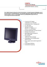
Avocent’s DSR appliances combine analog and digital technology to provide<br />
flexible, centralized control of data center servers. This solution provides<br />
enterprise customers with a significant reduction of cable volume, secure<br />
remote access and flexible server management from anywhere at anytime.<br />
The DSR appliance consists of a rack mountable keyboard, video and mouse<br />
(KVM) switch configurable for analog (local) or digital (remote) connectivity.<br />
Each DSR model has Avocent Rack Interface (ARI) ports for connecting<br />
servers and serial devices via DSRIQ modules. Video resolution of 1280 x 1024<br />
is supported for remote users of the DSR system. Enhanced video quality of<br />
up to 1600 x 1280 is available for the local user via the keyboard, video and<br />
mouse ports.<br />
The DSR works over standard LAN connections. Users can access servers (or<br />
serial devices) across a 100BaseT Ethernet connection or directly through a<br />
local port on the DSR for remote KVM access and administration, depending<br />
on the model selected. The IP-based DSR appliance gives you flexible server<br />
management control from anywhere in the world.<br />
Reduce cable bulk<br />
With server densities continually increasing, cable bulk remains one of the<br />
major concerns of every network administrator. The DSR significantly reduces<br />
KVM cable volume in the rack by utilizing the innovative DSRIQ module and<br />
single CAT 5 cabling. This allows a higher server density while providing<br />
greater airflow and cooling capacity.<br />
The built-in memory of the DSRIQ simplifies configuration by assigning<br />
and retaining unique server names or Electronic ID ( EID) numbers for<br />
each attached server. This integrated intelligence enhances security and<br />
prevents unauthorized access to a server through cable manipulation. The<br />
DSRIQ module is powered directly from the server and provides Keep Alive<br />
functionality whether or not the DSR appliance is powered up.<br />
The DSRIQ-SRL (serial) module is a DCE device that provides the primary<br />
interface between a serial device and a DSR appliance. It provides VT100<br />
terminal emulation, break suppression and port history in a convenient<br />
module. The DSRIQ-SRL is compatible with the ARI port of a DSR system.<br />
These DSRIQ modules eliminate the need for extra rack space or additional<br />
cables. The connection between the DSR system and DSRIQ modules is via<br />
industry standard UTP cabling.
4 DSR Installer/User Guide<br />
Access the DSR via network connection<br />
No special software or drivers are required on the attached, or host, computers.<br />
Users access the DSR appliance and all attached systems via Ethernet from a<br />
PC running the DSView TM application residing on the user PC. User PCs can be<br />
located anywhere a valid network connection exists. The DSR appliance can<br />
be configured on a separate network from your data network, allowing access<br />
to your servers even if your applications network is down.<br />
Simple point and click access to any server<br />
When a user activates DSView, it will display a listing of all computers and<br />
serial devices to which the user has permission to access. When a user selects<br />
a computer from the list, the video of the selected computer is displayed in a<br />
session window. Multiple servers can be accessed by one user. Each additional<br />
computer’s video will appear in a separate program window.<br />
Create and manage user permissions with DES<br />
encrypted security<br />
An administrator describes the configuration of computers attached to the DSR<br />
using an application called DSAdmin. Once the topology is described, the<br />
administrator then establishes which computers a user has permission to<br />
access. Usernames and passwords are derived from Windows NT ® , eliminating<br />
the need for redundant user databases. Once the topology is established, the<br />
DSAuth software manages the system’s user permissioning. DSView polls the<br />
server running DSAuth for access permissions on power up and every time a<br />
switch is initiated for the most current permissions possible. A refresh is also<br />
available for immediate updates to a user’s access profile. In addition to the<br />
permissioning function, DSAuth also stores pertinent information about<br />
attached devices in a database. Room location, rack location and computer<br />
type can all be stored for quick reference.<br />
Access serial devices<br />
If an Avocent CPS810 or CPS1610 appliance is attached to the DSR unit,<br />
operators can gain access to serial devices through the DSView software. When<br />
a user connects to the network using DSView, a listing of all computers and<br />
serial devices to which the user has permission to access displays. Selecting a<br />
serial device will initiate a Telnet session.
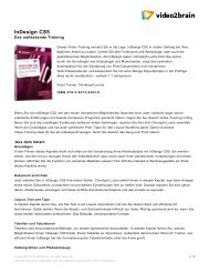
DSR2010<br />
Analog User<br />
(OSCAR)<br />
Figure 1.1: Example DSR Configuration<br />
TCP/IP<br />
<strong>Chapter</strong> 1: Product Overview 5<br />
Digital User<br />
(DSView)
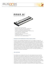
6 DSR Installer/User Guide<br />
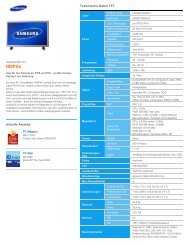
100-240V , 1.0A, 50-60 Hz<br />
DSR 800<br />
DSR 1010<br />
DSR 2010<br />
DSR 4010<br />
LAN<br />
LAN<br />
LAN<br />
Figure 1.2: DSR Model Comparison<br />
Safety Precautions<br />
1 3 5 7 9 11 13 15<br />
2 4 6 8 10 12 14 16<br />
1 3 5 7 9 11 13 15<br />
2 4 6 8 10 12 14 16<br />
1 3 5 7 9 11 13 15<br />
2 4 6 8 10 12 14 16<br />
To avoid potential video and/or keyboard problems when using Avocent products:<br />
• If the building has 3-phase AC power, ensure that the computer and monitor<br />
are on the same phase. For best results, they should be on the same circuit.<br />
To avoid potentially fatal shock hazard and possible damage to equipment,<br />
please observe the following precautions:<br />
• Do not use a 2-wire power cord in any Avocent product confi guration.<br />
• Test AC outlets at the computer and monitor for proper polarity<br />
and grounding.<br />
• Use only with grounded outlets at both the computer and monitor. When<br />
using a backup Uninterruptible Power Supply (UPS), power the computer,<br />
the monitor and the DSR appliance off the supply.<br />
NOTE: The AC inlet is the main disconnect.<br />
Number<br />
of<br />
servers<br />
Digital<br />
sessions/<br />
output<br />
8 1 1<br />
Analog<br />
user<br />
16 1 1<br />
16 2 1<br />
16 4 1
<strong>Chapter</strong> 1: Product Overview 7<br />
Rack mount safety considerations<br />
• Elevated Ambient Temperature: If installed in a closed rack assembly, the<br />
operation temperature of the rack environment may be greater than room<br />
ambient. Use care not to exceed the rated maximum ambient temperature<br />
of the appliance.<br />
• Reduced Air Flow: Installation of the equipment in a rack should be such<br />
that the amount of airfl ow required for safe operation of the equipment is<br />
not compromised.<br />
• Mechanical Loading: Mounting of the equipment in the rack should be such<br />
that a hazardous condition is not achieved due to uneven mechanical loading.<br />
• Circuit Overloading: Consideration should be given to the connection<br />
of the equipment to the supply circuit and the effect that overloading of<br />
circuits might have on overcurrent protection and supply wiring. Consider<br />
equipment nameplate ratings for maximum current.<br />
• Reliable Earthing: Reliable earthing of rack mounted equipment should<br />
be maintained. Pay particular attention to supply connections other than<br />
direct connections to the branch circuit (for example, use of power strips).
8 DSR Installer/User Guide
2 Installation<br />
Contents<br />
Getting Started . . . . . . . . . . . . . . . . . . . . . . . . . . . . . 11<br />
Installing the DSR Appliance . . . . . . . . . . . . . . . . . 13
<strong>Chapter</strong> 2: Installation<br />
<strong>Chapter</strong> 2: Installation 11<br />
The DSR system requires that the DSView, DSAdmin and DSAuth software be<br />
installed prior to use. DSView is the application that allows a user to view and<br />
control a server attached to the DSR system. DSAdmin is used to configure and<br />
maintain the system. DSAuth is a Windows NT or 2000 service used to prevent<br />
unauthorized access to the DSR system. More information on the DS<br />
Management Software suite can be found in your DSView Installer/<br />
User Guide.<br />
The DSR system uses Ethernet networking infrastructure and TCP/IP protocol<br />
to transmit keyboard, video and mouse information between operators and<br />
connected computers. Although 10BaseT Ethernet may be used, Avocent<br />
recommends a dedicated, switched 100BaseT network.<br />
Getting Started<br />
Before installing your DSR, refer to the following lists to ensure you have all items<br />
that shipped with the DSR as well as other items necessary for proper installation.<br />
Supplied with the DSR<br />
The following items are supplied with your DSR appliance:<br />
• DSR appliance<br />
• Local country power cord<br />
• Rack mounting brackets<br />
• Null modem cable<br />
• DSR Installer/User Guide<br />
• DSR Quick Install Guide<br />
Additional items needed<br />
The following are additional items needed to use your DSR appliance:<br />
• One DSRIQ module per server or DSRIQ-SRL per serial device<br />
• One CAT 5 patch cable per server or serial device (4-pair UTP, up to<br />
10 meters)<br />
• DS software
12 DSR Installer/User Guide<br />
Verification of Ethernet/computer connections<br />
DSR appliance<br />
The front panel of the DSR features two LEDs describing the Ethernet<br />
connection. The top green LED is the Link indicator. It will illuminate when a<br />
valid connection to the network is established and blink when there is activity<br />
on the port. The lower amber LED, labeled 100M, will indicate that you are<br />
communicating at the 100 Mb rate.<br />
Additionally, there are two LEDs above each port number on the front of your<br />
appliance: one green and one amber. The green LED will illuminate when the<br />
attached system is powered. The amber LED will illuminate when that port is<br />
selected by the DSView Client.<br />
DSRIQ modules<br />
PS/2, Sun and USB DSRIQ modules are available for attaching computers to<br />
your DSR appliance.<br />
The DSRIQ-SRL serial module is used to connect serial devices to your DSR<br />
appliance and features two green LEDs: a POWER LED and a STATUS LED.<br />
The POWER LED indicates that the attached computer is powered. The<br />
STATUS LED indicates that a valid UTP connection has been made to a DSR<br />
appliance. The DSRIQ-SRL prevents a serial break from the attached device if<br />
the module loses power. However, a user can generate a serial break with the<br />
attached device by pressing Alt-B in the Terminal Applications menu.<br />
Setting up your network<br />
The DSR system uses IP addresses to uniquely identify the server running<br />
DSAuth, the DSR appliances and the computers running DSView. The DSR<br />
supports both BootP (a subset of DHCP) and static IP addressing. Avocent<br />
recommends that IP addresses be reserved for each appliance and that they<br />
remain static while the DSR appliances are connected to the network. For<br />
additional information on how the DSR uses the TCP protocol, see Appendix B<br />
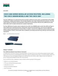
of the DSView Installer/User Guide. Figure 2.1 shows the DSR in a<br />
network configuration.
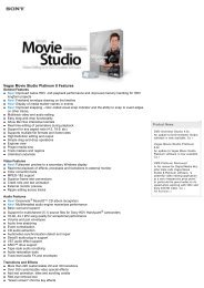
DSR2010<br />
Analog User<br />
(OSCAR)<br />
TCP/IP<br />
Figure 2.1: The DSR in a Network Configuration<br />
Installing the DSR Appliance<br />
<strong>Chapter</strong> 2: Installation 13<br />
Authentication<br />
Services<br />
(DSAdmin)<br />
Digital User<br />
(DSView)<br />
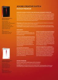
The following diagram illustrates one possible configuration for your DSR<br />
appliance. Follow the detailed instructions to successfully install your<br />
DSR appliance.
14 DSR Installer/User Guide<br />
Power<br />
Cord<br />
Confi guration Port<br />
for updating<br />
fi rmware<br />
Figure 2.2: Basic DSR Configuration<br />
LAN<br />
Analog User<br />
Network<br />
KVM<br />
Connections<br />
CAT 5<br />
Cable<br />
Digital User<br />
DSR1010 Appliance<br />
ARI Ports 1-16<br />
Servers 2-16<br />
DSRIQ Module<br />
PS/2, USB, Sun and serial adaptors<br />
are available Server 1<br />
WARNING: To reduce the risk of electric shock or damage to your equipment-<br />
- Do not disable the power cord grounding plug. The grounding plug is an important safety feature.<br />
- Plug the power cord into a grounded (earthed) outlet that is easily accessible at all times.<br />
- Disconnect the power from the appliance by unplugging the power cord from either the<br />
electrical outlet or the appliance.
To install the DSR hardware:<br />
1. Remove the DSR appliance from the packing material.<br />
<strong>Chapter</strong> 2: Installation 15<br />
2. Connect a terminal or PC running terminal emulation software (such as<br />
HyperTerminal ® ) to the Confi guration port on the back panel of the DSR<br />
appliance using the supplied null modem cable. The terminal should be<br />
set to 9600 baud, 8 bits, 1 stop bit, no parity and no fl ow control.<br />
3. Plug the supplied power cord into the back of the DSR appliance and then<br />
into an appropriate power source.<br />
4. When the power is switched on, the Power indicator on the front of the<br />
appliance will blink for approximately 30 seconds while performing a selftest.<br />
Approximately 10 seconds after it stops blinking, press the Enter key<br />
to access the main menu.<br />
NOTE: The DSR appliance may be rack mounted in a 1U confi guration. The DSR does not<br />
support a ØU confi guration.<br />
To confi gure the DSR hardware:<br />
1. You will see the Terminal Applications menu with six options. Select<br />
option 1, Network Confi guration.<br />
Figure 2.3: Network Configuration Menu<br />
2. Select option 1 to set your network speed. When possible, you should set<br />
your connection manually without relying on the auto negotiate feature.<br />
Once you enter your selection, you will be returned to the Network<br />
Confi guration menu.
16 DSR Installer/User Guide<br />
3. Select option 2 and specify if you are using a static or BootP IP address.<br />
Avocent recommends using a static IP address for ease of confi guration. If<br />
you are using a BootP address, please confi gure your BootP server to<br />
provide an IP address to the DSR appliance, skip step 4 and continue to<br />
the next procedure.<br />
4. Select options 3-5 from the Terminal Applications menu, in turn, to fi nish<br />
confi guring your DSR for IP address, netmask and default gateway. Once<br />
this is completed, type a Ø to return to the main menu.<br />
Adjusting mouse settings on target machines<br />
NOTE: We highly recommend that all Windows systems attached to the DSR use the default<br />
Windows PS/2 mouse driver.<br />
Before a PC running Windows NT, 2000 or XP can be connected to the DSR for<br />
remote user control, an adjustment to the target mouse’s Motion tab must be<br />
made. Use the default Microsoft ® Windows ® PS/2 mouse driver for all Microsoft<br />
Windows systems attached to the appliance.<br />
For Microsoft Windows NT (using default drivers):<br />
1. From the Desktop, select Start - Settings - Control Panel - Mouse. The<br />
Mouse Properties dialog box will appear.<br />
2. Click on the Motion tab.<br />
3. Set the Pointer speed to Slow. This will also need to be done for any NT<br />
user account that will be accessing the NT system through the DSR.<br />
4. Set Acceleration to None for mouse sync.<br />
For Windows 2000 or Windows XP (using default drivers):<br />
1. From the Desktop, select Start - Settings - Control Panel - Mouse. The<br />
Mouse Properties dialog box will appear.<br />
2. Click on the Motion tab.<br />
3. Set the speed setting to the default of 50%.<br />
4. If you are using Windows 2000, click the Mouse tab and set Acceleration to<br />
None for mouse sync.<br />
-or-<br />
If you are using Windows XP, click the Pointer Options tab and check the<br />
Enhance pointer precision checkbox.
To connect a DSRIQ module to each server:<br />
1. Locate a DSRIQ for your DSR appliance.<br />
<strong>Chapter</strong> 2: Installation 17<br />
2. Attach the appropriately color-coded ends to the keyboard (violet), monitor<br />
(blue) and mouse (green) ports on the fi rst server you will be connecting to<br />
this DSR appliance.<br />
3. Attach one end of the CAT 5 cabling that will run from your DSRIQ to the<br />
DSR appliance to the RJ-45 connector on the DSRIQ.<br />
4. Connect the other end of the CAT 5 cable to the desired ARI port on the<br />
back of your DSR appliance.<br />
5. Repeat this step for all servers you wish to attach.<br />
NOTE: When connecting a Sun DSRIQ module, you must use a multi-sync monitor to<br />
accommodate Sun computers that support both VGA and sync-on-green or composite sync.<br />
NOTE: Power down the DSR appliance before servicing. Always disconnect the power cord from<br />
the wall outlet.<br />
To connect serial devices to the DSR appliance:<br />
1. Locate a DSRIQ-SRL module.<br />
2. Attach the DSRIQ-SRL 9-pin serial connector to the serial port of the<br />
device to be connected to your DSR appliance.<br />
3. Attach one end of the CAT 5 cable to the RJ-45 connector on the DSRIQ-<br />
SRL module. Connect the other end of the CAT 5 cable to the desired ARI<br />
port on the back of your DSR appliance.<br />
NOTE: The DSRIQ-SRL module is a DCE device and only supports VT100 terminal emulation.<br />
4. Connect the power supply to the power connector on your DSRIQ-SRL.<br />
The cable expander can be used to power up to four DSRIQ-SRL modules<br />
from a single power supply.<br />
5. Connect the DSRIQ-SRL power supply to an appropriate AC wall outlet.<br />
Power up your serial device. See Appendix B for more information on<br />
DSRIQ-SRL modules.<br />
To connect the local port keyboard, monitor and mouse:<br />
Attach your keyboard, monitor and mouse cable connectors to the appropriate<br />
ports on the back of your DSR appliance.<br />
NOTE: You must install both a keyboard and mouse on the local port or the keyboard will not<br />
initialize properly.
18 DSR Installer/User Guide<br />
Adding a legacy KVM switch<br />
You can add your legacy KVM switches to the DSR appliance for better<br />
integration into your existing configuration. In a cascaded system, each ARI port<br />
will accommodate up to 24 servers.<br />
Legacy Switch Support<br />
Legacy Product Model Numbers<br />
OutLook ® ES 140ES, 180ES, 280ES, 1160ES, 2160ES, 4160ES<br />
AutoView ® AV200-4, AV200-8, AV400-4, AV400-8, AV416, AV424, AV2000-AM<br />
Power<br />
Cord<br />
Analog User<br />
KVM Connections<br />
CAT 5 Cable<br />
DSR1010<br />
Appliance<br />
DSRIQ Module<br />
PS/2, USB, Sun and<br />
serial modules are available<br />
DSRIQ<br />
Module AutoView<br />
200/400<br />
Outlook ES Switch<br />
Switch<br />
Server 1 Server 1<br />
Figure 2.4: DSR1010 Configuration with a Legacy KVM Switch<br />
To add a legacy KVM switch:<br />
1. Mount the legacy KVM switch into your rack cabinet. Locate a length of<br />
CAT 5 cabling to connect your DSR to the DSRIQ module for your<br />
legacy KVM switch.<br />
2. Attach one end of the CAT 5 cabling to the RJ-45 connector on the<br />
DSRIQ module.<br />
3. Connect the other end of the CAT 5 cable to a port on the back of your<br />
DSR appliance.
<strong>Chapter</strong> 2: Installation 19<br />
4. Attach the keyboard, monitor and mouse connectors of the DSRIQ module<br />
to a user port on your legacy KVM switch.<br />
5. Connect the servers to your legacy KVM switch according to the<br />
instructions included with the device.<br />
6. Power cycle the legacy KVM switch to enable the cascade code.<br />
7. Repeat steps 2-6 for all legacy KVM switches you want to attach to your<br />
system as cascading switches.<br />
To connect and power up your DSR:<br />
1. Connect your network cable from the LAN port on the rear of the DSR to<br />
your network.<br />
2. Power up all attached systems.<br />
To install your DSR software:<br />
See the DSView Installer/User Guide that ships with your software.<br />
NOTE: Your software registration key will be necessary for installing the DSAuth software used<br />
with your DSR appliance. Internet Explorer 5.0 or higher and Java Runtime Environment JRE<br />
1.4.[X] must also be installed to use the DSWebview components of the DSView software.
20 DSR Installer/User Guide
3 Local<br />
Port Operation<br />
Contents<br />
Controlling Your System at the Local Port . . . . . . 23<br />
Viewing and Selecting Ports and Servers . . . . . . . . 23<br />
Navigating OSCAR . . . . . . . . . . . . . . . . . . . . . . . . . 25<br />
Configuring OSCAR . . . . . . . . . . . . . . . . . . . . . . . . 27<br />
Assigning Device Types . . . . . . . . . . . . . . . . . . . . . . 29<br />
Changing the Display Behavior . . . . . . . . . . . . . . . 31<br />
Controlling the Status Flag . . . . . . . . . . . . . . . . . . . 33<br />
Broadcasting to Servers . . . . . . . . . . . . . . . . . . . . . . 34<br />
Using Scan Mode . . . . . . . . . . . . . . . . . . . . . . . . . . . 36<br />
Setting Console Security . . . . . . . . . . . . . . . . . . . . . 38<br />
Setting the Keyboard Country Code . . . . . . . . . . . . 41<br />
Managing Server Tasks Using OSCAR . . . . . . . . . 42<br />
Viewing and Disconnecting User Connections . . . 44<br />
Resetting Your PS/2 Keyboard and Mouse . . . . . . 45<br />
Displaying Version Information . . . . . . . . . . . . . . . 46
<strong>Chapter</strong> 3: Local Port Operation<br />
<strong>Chapter</strong> 3: Local Port Operation 23<br />
Controlling Your System at the Local Port<br />
All DSR models include a local port on the back of the appliance. This port<br />
allows you to connect a keyboard, monitor and mouse to the appliance for<br />
direct access. The DSR uses OSCAR ® , Avocent’s On-Screen Configuration<br />
and Activity Reporting interface, which has intuitive menus to configure your<br />
system and select computers. Computers can be identified by name or number,<br />
allowing you to customize server names.<br />
Viewing and Selecting Ports and Servers<br />
Use the Main dialog box to view, configure and control servers in the DSR<br />
system. You may view your servers by name, port or by the unique Electronic<br />
ID number (EID) embedded in each DSRIQ. You will see an OSCAR-generated<br />
port list by default when you first launch OSCAR.<br />
The Port column indicates the ARI port to which a server is connected. If you<br />
connect a legacy KVM switch to the DSR appliance, the port numbering<br />
displays the ARI port first, then the switch port to which the server is<br />
connected. For example, in Figure 3.1, all the servers except Darrell and Ebert<br />
are connected to legacy switches.<br />
To access the Main dialog box:<br />
Press Print Screen to launch OSCAR. The Main dialog box will appear.<br />
Figure 3.1: Main Dialog Box
24 DSR Installer/User Guide<br />
Viewing the status of your DSR system<br />
The status of servers in your system is indicated in the far right columns of the<br />
Main dialog box. The following table describes the status symbols.<br />
OSCAR Status Symbols<br />
Symbol Description<br />
(green circle) Server connected, powered up and the DSRIQ is online.<br />
Connected server is powered down or is not operating properly and the<br />
DSRIQ is offl ine.<br />
Connected switch is online.<br />
Connected switch is offl ine or not operating properly.<br />
(yellow circle) The designated DSRIQ module is being upgraded. When this<br />
symbol displays, do not cycle power to the DSR appliance or connected servers<br />
and do not disconnect DSRIQ modules. Doing so may render the module<br />
permanently inoperable and require the DSRIQ to be returned to the factory for repair.<br />
(green letter) DSRIQ is being accessed by the indicated user channel.<br />
(black letter) DSRIQ is blocked by the indicated user channel. For instance, in<br />
Figure 3.1, user B is viewing Forester, but is blocking access to Acton, Barrett<br />
and Edie which are connected to the same DSRIQ.<br />
Selecting servers and serial devices<br />
Use the Main dialog box to select servers and serial devices. When you select<br />
a server or serial device, the DSR reconfigures the keyboard and mouse to the<br />
settings for the selected server or serial device.<br />
To select servers or serial devices:<br />
Double-click the server or serial device name, EID or port number.<br />
—or—<br />
If the display order of your list is by port (Port button is depressed), type the<br />
port number and press Enter.<br />
—or—<br />
If the display order of your list is by name or EID (Name or EID button is<br />
depressed), type the first few letters of the name of the server or serial device,<br />
or the EID number to establish it as unique, and press Enter.<br />
To select the previous server or serial device:<br />
Press Print Screen and then Backspace. This key combination toggles you<br />
between the previous and current connections.
To disconnect from a server or serial device:<br />
<strong>Chapter</strong> 3: Local Port Operation 25<br />
Press Print Screen and then Alt+Ø. This leaves the user in a free state, with no<br />
server or serial device selected. The status flag on your desktop displays Free.<br />
Soft switching<br />
Soft switching is the ability to switch servers using a hotkey sequence. You can<br />
soft switch to a server by pressing Print Screen and then typing the first few<br />
characters of its name or number. If you have set a Screen Delay Time and you<br />
press the key sequences before that time has elapsed, OSCAR will not display.<br />
To confi gure servers for soft switching:<br />
1. Press Print Screen to launch OSCAR. The Main dialog box appears.<br />
2. Click Setup - Menu. The Menu dialog box appears.<br />
3. For Screen Delay Time, type the number of seconds of delay desired<br />
before the Main dialog box is displayed after Print Screen is pressed.<br />
4. Click OK.<br />
To soft switch to a server:<br />
1. To select a server, press Print Screen. If the display order of your server list<br />
is by port (Port button is depressed), type the port number and press Enter.<br />
—or—<br />
If the display order of your server list is by name (Name button is<br />
depressed), type the fi rst few letters of the name of the server to establish<br />
it as unique, and press Enter.<br />
2. To switch back to the previous server, press Print Screen then Backspace.<br />
Navigating OSCAR<br />
This table describes how to navigate OSCAR using the keyboard and mouse.<br />
OSCAR Navigation Basics<br />
This Keystroke Does This<br />
Print Screen Opens OSCAR. Press Print Screen twice to send the Print<br />
Screen keystroke to the currently selected DSRIQ module.<br />
F1 Opens the Help screen for the current dialog box.
26 DSR Installer/User Guide<br />
OSCAR Navigation Basics (continued)<br />
This Keystroke Does This<br />
Escape Closes the current dialog box without saving changes and<br />
returns to the previous one. If the Main dialog box is displayed,<br />
pressing Escape closes OSCAR and displays a status fl ag if<br />
status fl ags are enabled. See Controlling the Status Flag in this<br />
chapter for more information. In a message box, it closes the<br />
pop-up box and returns to the current dialog box.<br />
Alt Opens dialog boxes, selects or checks options and executes<br />
actions when used with underlined or other designated letters.<br />
Alt+X Closes current dialog box and returns to previous one.<br />
Alt+O Selects the OK button, then returns to the previous dialog box.<br />
Enter Completes a switch operation in the Main dialog box and<br />
exits OSCAR.<br />
Single-click, Enter In a text box, it selects the text for editing and enables the Left<br />
and Right Arrow keys to move the cursor. Press Enter again<br />
to quit the edit mode.<br />
Print Screen, Backspace Toggles back to previous selection.<br />
Print Screen, Alt+Ø Immediately disengages user from a server; no server is<br />
selected. Status fl ag displays Free. (This only applies to the Ø<br />
on the keyboard and not the keypad.)<br />
Print Screen, Pause Immediately turns on screen saver mode and prevents access to<br />
that specifi c console, if it is password protected.<br />
Up/Down Arrows Moves the cursor from line to line in lists.<br />
Right/Left Arrows Moves the cursor between columns. When editing a text box,<br />
these keys move the cursor within the column.<br />
Page Up/Page Down Pages up and down through Name and Port lists and<br />
Help pages.<br />
Home/End Moves the cursor to the top or bottom of a list.<br />
Backspace Erases characters in a text box.<br />
Delete Deletes current selection in the scan list or characters in a<br />
text box.<br />
Shift-Del Deletes from the current selection to the end of the list when<br />
editing a scan list.<br />
Numbers Type from the keyboard or keypad.<br />
Caps Lock Disabled. Use the Shift key to change case.
Configuring OSCAR<br />
<strong>Chapter</strong> 3: Local Port Operation 27<br />
You can configure your DSR system from the Setup menu within OSCAR.<br />
Select the Names button when initially setting up your DSR system to identify<br />
servers by unique names. Select the other setup features to manage routine<br />
tasks for your servers from the OSCAR menu.<br />
Setup Features to Confi gure OSCAR<br />
Feature Purpose<br />
Menu Change the server list between numerical by port or EID number and alphabetical<br />
by name<br />
Change the Screen Delay Time before OSCAR displays after pressing<br />
Print Screen<br />
Flag Change display, timing, color or location of the status fl ag<br />
Broadcast Simultaneously send mouse movements and keystrokes to multiple servers<br />
Scan Set up a custom scan pattern for up to 16 servers<br />
Security Set passwords to protect or restrict server access<br />
Enable the screen saver<br />
Keyboard Set the keyboard country code to send to Sun servers<br />
Devices Identify the appropriate number of ports on an attached cascade switch<br />
Names Identify servers by unique names<br />
To access the Setup menu:<br />
1. Press Print Screen to launch OSCAR. The Main dialog box appears.<br />
2. Click Setup. The Setup dialog box appears.<br />
Figure 3.2: Setup Dialog Box
28 DSR Installer/User Guide<br />
Assigning server or serial device names<br />
Use the Names dialog box to identify servers or serial devices by name rather than<br />
by port number. The Names list is always sorted by port order. You can toggle<br />
between displaying the name or the EID number of each DSRIQ, so even if<br />
you move the module/server/serial device to another ARI port, the name and<br />
configuration will be recognized by the appliance.<br />
NOTE: If a server is turned off, its respective DSRIQ will not appear in the Names list.<br />
To access the Names dialog box:<br />
1. If OSCAR is not open, press Print Screen. The Main dialog box appears.<br />
2. Click Setup - Names. The Names dialog box appears.<br />
Figure 3.3: Names Dialog Box<br />
NOTE: If new DSRIQ modules are discovered by the DSR, the on-screen list will be automatically<br />
updated. The mouse cursor will change into an hourglass during the update. No mouse or<br />
keyboard input will be accepted until the list update is complete.<br />
To assign names to servers or serial devices:<br />
1. In the Names dialog box, select a server or serial device name or port<br />
number and click Modify. The Name Modify dialog box appears.
Figure 3.4: Name Modify Dialog Box<br />
<strong>Chapter</strong> 3: Local Port Operation 29<br />
2. Type a name in the New Name box. Names of servers or serial devices may<br />
be up to 15 characters long. Legal characters include: A-Z, a-z, Ø-9, space<br />
and hyphen.<br />
3. Click OK to transfer the new name to the Names dialog box. Your selection<br />
is not saved until you click OK in the Names dialog box.<br />
4. Repeat steps 1-3 for each server or serial device in the system.<br />
5. Click OK in the Names dialog box to save your changes.<br />
—or—<br />
Click X or press Escape to exit the dialog box without saving changes.<br />
NOTE: If a DSRIQ has not been assigned a name, a combination of the EID and port is used as<br />
the default name.<br />
To list servers alphabetically by name:<br />
Press Alt+N or click Name in the Main dialog box.<br />
Assigning Device Types<br />
While the appliance automatically discovers cascade switches attached to<br />
your appliance, you will need to specify the number of ports on the cascade<br />
switch through the Devices dialog box. You will see an Sw-4, Sw-6, Sw-8, Sw-<br />
16 or Sw-24 appear in the Type category for the cascade switch. Select the<br />
switch from the list and the Modify button appears, allowing you to assign<br />
the appropriate number of ports to it.
30 DSR Installer/User Guide<br />
To access the Devices dialog box:<br />
1. If OSCAR is not open, press Print Screen. The Main dialog box will appear.<br />
2. Click Setup - Devices. The Devices dialog box appears.<br />
NOTE: The Modify button will only be available if a confi gurable switch is selected.<br />
Figure 3.5: Devices Dialog Box<br />
When the DSR discovers a cascade switch, you will notice the numbering<br />
format change from being an ARI port only to [ARI port]-[switch port] to<br />
accommodate each server under that switch.<br />
For example, if a switch is connected to ARI port 6, each server connected to<br />
it would be numbered sequentially. The server using ARI port 6, switch port<br />
1 would be 06-01, the server using ARI port 6, switch port 2 would be 06-02<br />
and so on.<br />
To assign a device type:<br />
1. In the Devices dialog box, select the desired port number.<br />
2. Click Modify. The Device Modify dialog box appears.
Figure 3.6: Device Modify Dialog Box<br />
<strong>Chapter</strong> 3: Local Port Operation 31<br />
3. Choose the number of ports supported by your switch and click OK.<br />
4. Repeat steps 1–3 for each port requiring a device type to be assigned.<br />
5. Click OK in the Devices dialog box to save settings.<br />
NOTE: Changes made in the Device Modify dialog box are not saved until you click OK in the<br />
Devices dialog box.<br />
Changing the Display Behavior<br />
Use the Menu dialog box to change the display order of servers and set a<br />
Screen Delay Time for OSCAR. The display order setting alters how servers<br />
will display in several screens including the Main, Devices and Broadcast<br />
dialog boxes.<br />
To access the Menu dialog box:<br />
1. Press Print Screen to launch OSCAR. The Main dialog box appears.<br />
2. Click Setup - Menu in the Main dialog box. The Main setup menu appears<br />
(see Figure 3.7).
32 DSR Installer/User Guide<br />
Figure 3.7: Menu Dialog Box<br />
To choose the display order of servers:<br />
1. Select Name to display servers alphabetically by name.<br />
—or—<br />
Select EID to display servers numerically by EID number.<br />
—or—<br />
Select Port to display servers numerically by port number.<br />
2. Click OK.<br />
Depending on the display method selected, the corresponding button will be<br />
depressed in the Main dialog box.<br />
To set a Screen Delay Time for OSCAR:<br />
1. Type in the number of seconds (Ø-9) to delay OSCAR display after you<br />
press Print Screen. Entering Ø will instantly launch OSCAR with no delay.<br />
2. Click OK.<br />
Setting a Screen Delay Time allows you to complete a soft switch without<br />
OSCAR displaying. To perform a soft switch, see Soft switching in this chapter.
Controlling the Status Flag<br />
<strong>Chapter</strong> 3: Local Port Operation 33<br />
The status flag displays on your desktop and shows the name or EID number<br />
of the selected server or the status of the selected port. Use the Flag dialog box<br />
to confi gure the fl ag to display by server name or EID number, or to change<br />
the fl ag color, opacity, display time and location on the desktop.<br />
OSCAR Status Flags<br />
Flag Description<br />
Flag type by name<br />
Flag type by EID number<br />
To access the Flag dialog box:<br />
Flag indicating that the user has been disconnected from all systems<br />
Flag indicating that broadcast mode is enabled<br />
1. If OSCAR is not open, press Print Screen. The Main dialog box will appear.<br />
2. Click Setup - Flag. The Flag dialog box appears.<br />
Figure 3.8: Flag Dialog Box<br />
To determine how the status fl ag is displayed:<br />
1. Select Name or EID to determine what information will be displayed.<br />
2. Select Displayed to show the fl ag all the time or select Timed to display the<br />
fl ag for only fi ve seconds after switching.
34 DSR Installer/User Guide<br />
3. Select a fl ag color in Display Color. The following fl ag colors are available:<br />
• Flag 1 - Grey fl ag with black text<br />
• Flag 2 - White fl ag with red text<br />
• Flag 3 - White fl ag with blue text<br />
• Flag 4 - White fl ag with violet text<br />
4. In Display Mode, select Opaque for a solid color fl ag or select Transparent<br />
to see the desktop through the fl ag.<br />
5. To position the status fl ag on the desktop:<br />
a. Click Set Position to gain access to the Position Flag screen.<br />
Figure 3.9: Position Flag<br />
b. Left-click on the title bar and drag to the desired location.<br />
c. Right-click to return to the Flag dialog box.<br />
NOTE: Changes made to the fl ag position are not saved until you click OK in the Flag dialog box.<br />
6. Click OK to save settings.<br />
—or—<br />
Click X to exit without saving changes.<br />
Broadcasting to Servers<br />
The local user can simultaneously control multiple servers in a system, to<br />
ensure that all selected servers receive identical input. You can choose to<br />
broadcast keystrokes and/or mouse movements independently.<br />
NOTE: You can broadcast to as many as 16 servers at a time, one server per ARI port.<br />
To access the Broadcast dialog box:<br />
1. If OSCAR is not open, press Print Screen. The Main dialog box will appear.<br />
2. Click Setup - Broadcast. The Broadcast dialog box appears.
Figure 3.10: Broadcast Dialog Box<br />
<strong>Chapter</strong> 3: Local Port Operation 35<br />
NOTE: Broadcasting Keystrokes - The keyboard state must be identical for all servers<br />
receiving a broadcast to interpret keystrokes identically. Specifi cally, the Caps Lock and Num<br />
Lock modes must be the same on all keyboards. While the appliance attempts to send<br />
keystrokes to the selected servers simultaneously, some servers may inhibit and thereby delay<br />
the transmission.<br />
Broadcasting Mouse Movements - For the mouse to work accurately, all systems must have<br />
identical mouse drivers, desktops (such as identically placed icons) and video resolutions. In<br />
addition, the mouse must be in exactly the same place on all screens. Because these conditions<br />
are extremely diffi cult to achieve, broadcasting mouse movements to multiple systems may have<br />
unpredictable results.<br />
To broadcast to selected servers:<br />
1. From the Broadcast dialog box, select the mouse and/or keyboard<br />
checkboxes for the servers that are to receive the broadcast commands.<br />
-or-<br />
Press the Up or Down Arrow keys to move the cursor to the target server.<br />
Then press Alt+K to select the keyboard checkbox and/or Alt+M to select<br />
the mouse checkbox. Repeat for additional servers.<br />
2. Click OK to save the settings and return to the Setup dialog box. Click X or<br />
press Escape to return to the Main dialog box.<br />
3. Click Commands. The Commands dialog box appears.<br />
4. Click the Broadcast Enable checkbox to activate broadcasting.<br />
5. From the user station, type the information and/or perform the mouse<br />
movements you want to broadcast.
36 DSR Installer/User Guide<br />
To turn broadcasting off:<br />
From the Commands dialog box, clear the Broadcast Enable checkbox.<br />
Using Scan Mode<br />
In scan mode, the DSR appliance automatically scans from port to port (server<br />
to server). You can scan up to 16 servers, specifying which servers to scan and<br />
the number of seconds that each server will display. The scanning order is<br />
determined by placement of the server in the list. The list is always shown in<br />
scanning order. You can, however, choose to display the server’s name or EID<br />
number by pressing the appropriate button.<br />
NOTE: Scanning is only available to the local user.<br />
To add servers to the scan list:<br />
1. If OSCAR is not open, press Print Screen. The Main dialog box will appear.<br />
2. Click Setup - Scan. The Scan dialog box appears.<br />
Figure 3.11: Scan Dialog Box<br />
3. Determine the order within the list to add the server. If there are no servers<br />
in the scan list, your cursor will appear in a blank line at the top of the list.<br />
-or-<br />
To add a server to the end of the list, place your cursor in the last server<br />
entry and press the Down Arrow key.
<strong>Chapter</strong> 3: Local Port Operation 37<br />
-or-<br />
To add a server in the midst of an existing list, place your cursor in the line<br />
below where you want to insert a new server and press Insert.<br />
4. Type the fi rst few characters of a server name or port number to scan. The<br />
fi rst matching server will appear in the line.<br />
-or-<br />
To move through the list, press the following keyboard commands in the<br />
Name, Port or Time column to move through the list of servers available<br />
to scan.<br />
a. Press Alt+Down Arrow to move the cursor down through the list<br />
of servers.<br />
b. Press Alt+Up Arrow to move the cursor up through the list of servers.<br />
c. Press Alt+Home to move the cursor to the fi rst server in the list.<br />
d. Press Alt+End to move the cursor to the last server in the list.<br />
5. In the Time column, type the number of seconds (from 3-255) of desired<br />
time before the scan moves to the next server in the sequence.<br />
6. Move the cursor to the next line or press Down Arrow and repeat steps 2-5<br />
for each of the remaining servers to be included in the scan pattern.<br />
7. Click OK.<br />
To remove a server from the scan list:<br />
1. In the Scan dialog box, click the server to be removed.<br />
2. Press Delete.<br />
-or-<br />
Press Shift+Delete to remove the selected server and all entries below it.<br />
3. Click OK.<br />
To start the scan mode:<br />
1. If OSCAR is not open, press Print Screen. The Main dialog box will appear.<br />
2. Click Commands. The Commands dialog box appears.
38 DSR Installer/User Guide<br />
Figure 3.12: Commands Dialog Box<br />
3. Select Scan Enable in the Commands dialog box.<br />
4. Click X to close the Commands dialog box.<br />
NOTE: Scanning will begin as soon as the scan button is checked.<br />
To cancel scan mode:<br />
1. Select a server if OSCAR is open.<br />
-or-<br />
Move the mouse or press any key on the keyboard if OSCAR is not open.<br />
Scanning will stop at the currently selected server.<br />
-or-<br />
If OSCAR is not open, press Print Screen. The Main dialog box will appear.<br />
2. Click Commands. The Commands dialog box appears.<br />
3. Clear Scan Enable.<br />
Setting Console Security<br />
Use the Security dialog box to set security on your local port console. You can<br />
establish a screen saver mode that engages after your console remains unused<br />
for a specified Inactivity Time. Once engaged, your console will remain locked<br />
until you press any key or move the mouse. You will then need to type in your<br />
password to continue.<br />
Use the Security dialog box to lock your console with password protection, set<br />
or change your password and enable the screen saver.
<strong>Chapter</strong> 3: Local Port Operation 39<br />
NOTE: If a password has been previously set, you will have to enter the password before you can<br />
access the Security dialog box.<br />
To access the Security dialog box:<br />
1. If OSCAR is not open, press Print Screen. The Main dialog box will appear.<br />
2. Click Setup - Security. The Security dialog box appears.<br />
Figure 3.13: Security Dialog Box<br />
To set or change the password:<br />
1. Single-click and press Enter or double-click in the New text box.<br />
2. Type the new password in the New text box and press Enter. Passwords<br />
must contain both alpha and numeric characters, are case sensitive and<br />
may be up to 12 characters long. Legal characters are: A-Z, a-z, Ø-9, space<br />
and hyphen.<br />
3. In the Repeat box, type the password again and press Enter.<br />
4. Click OK to change only your password, and then close the dialog box.<br />
NOTE: If you should lose or forget your password, you will need to return your switch to have it<br />
reset to the factory default settings. See Appendix F: Technical Support for contact information.<br />
To password protect your console:<br />
1. Set your password as described in the previous procedure.<br />
2. Select Enable Screen Saver.
40 DSR Installer/User Guide<br />
3. Type the number of minutes for Inactivity Time (from 1-99) to delay<br />
activation of password protection and the screen saver feature.<br />
4. For Mode, select Energy if your monitor is ENERGY STAR ® compliant;<br />
otherwise select Screen.<br />
CAUTION: Monitor damage can result from the use of Energy mode with monitors not compliant<br />
with ENERGY STAR ® .<br />
5. (Optional) Click Test to activate the screen saver test which lasts 10<br />
seconds then returns you to the Security dialog box.<br />
6. Click OK.<br />
To log in to your console:<br />
1. Press any key or move the mouse.<br />
2. The Password dialog box appears. Type your password, and then click OK.<br />
3. The Main dialog box appears if the password was entered correctly.<br />
To remove password protection from your console:<br />
1. From the Main dialog box, click Setup - Security; the Password dialog box<br />
appears. Type your password, and then click OK.<br />
2. In the Security dialog box, single-click and press Enter or double-click in<br />
the New box. Leave the box blank. Press Enter.<br />
3. Single-click and press Enter or double-click in the Repeat box. Leave the<br />
box blank. Press Enter.<br />
4. Click OK to eliminate your password.<br />
To enable the screen saver mode with no password protection:<br />
1. If your console does not require a password to gain access to the Security<br />
box, go to step 2.<br />
—or—<br />
If your console is password protected, see the previous procedure, then go<br />
to step 2.<br />
2. Select Enable Screen Saver.<br />
3. Type the number of minutes for Inactivity Time (from 1–99) to delay<br />
activation of the screen saver.<br />
4. Choose Energy if your monitor is ENERGY STAR compliant; otherwise<br />
select Screen.
<strong>Chapter</strong> 3: Local Port Operation 41<br />
CAUTION: Monitor damage can result from the use of Energy Mode with monitors not compliant<br />
with ENERGY STAR ® .<br />
5. (Optional) Click Test to activate the screen saver test which lasts 10<br />
seconds then returns you to the Security dialog box.<br />
6. Click OK.<br />
NOTE: Activation of the screen saver mode disconnects the user from a server; no server is<br />
selected. The status fl ag displays Free.<br />
To exit the screen saver mode:<br />
Press any key or move your mouse. Any previous server connection will<br />
be restored.<br />
To turn off the screen saver:<br />
1. In the Security dialog box, clear Enable Screen Saver.<br />
2. Click OK.<br />
To immediately turn on the screen saver:<br />
Press Print Screen, then press Pause. This command only works when the<br />
user is connected to a server.<br />
Setting the Keyboard Country Code<br />
NOTE: Using a keyboard code that supports a language different from that of your DSR<br />
fi r mwa r e w i l l c ause incorrect keyboard mapping.<br />
Sun servers may use key mappings for foreign keyboards. By default, DS<br />
appliances send the US keyboard country code to Sun and USB modules<br />
attached to servers, and the code is applied to the servers when they are<br />
powered up or rebooted. Codes are then stored in the DSRIQ.<br />
Issues may arise when you use the US keyboard country code with a keyboard<br />
of another country. For example, the Z key on a US keyboard is in the same<br />
location as the Y key on a German keyboard. Sun servers will interpret<br />
pressing the Y key on a German keyboard as pressing the Z key when the US<br />
keyboard country code is used.<br />
The Keyboard command enables you to send a different keyboard country<br />
code than the default US setting. The specified country code is sent to all<br />
servers attached to the DS appliance when they are powered up or rebooted,<br />
and the new code is stored in the DSRIQ.
42 DSR Installer/User Guide<br />
NOTE: If a DSRIQ is moved to a different server, the keyboard country code will need to be reset.<br />
See Appendix E for information on emulating certain Sun keys using a PS/2<br />
keyboard and special considerations for Japanese and Korean Sun<br />
USB keyboards.<br />
NOTE: Only local users can view or change keyboard country code settings.<br />
To set the keyboard country code for Sun servers:<br />
1. If OSCAR is not open, press Print Screen. The Main dialog box will appear.<br />
2. Click Setup - Keyboard. The Keyboard dialog box appears.<br />
Figure 3.14: Keyboard Dialog Box<br />
3. Select a country code and click OK.<br />
4. Reboot the Sun servers. After rebooting, each Sun server will request the<br />
country code setting stored in the DSRIQ.<br />
NOTE: If you wish to reboot the servers by power-cycling them, you must wait 90 seconds<br />
before rebooting. A soft reboot may be performed without waiting 90 seconds.<br />
Managing Server Tasks Using OSCAR<br />
From the OSCAR Commands menu, you can manage your DSR system and<br />
user connections, engage the scan and broadcast modes and update<br />
your firmware.
<strong>Chapter</strong> 3: Local Port Operation 43<br />
Commands to Manage Routine Tasks for Your Servers<br />
Feature Purpose<br />
Broadcast Enable Begin broadcasting to your servers. Confi gure a server list for<br />
broadcasting under the Setup dialog box.<br />
Scan Enable Begin scanning your servers. Set up a server list for scanning in the<br />
Setup dialog box.<br />
User Status View and disconnect users.<br />
Reset PS/2 Re-establish operation of PS/2 keyboard and mouse.<br />
Display Versions View version information for the DSR appliance as well as view and<br />
upgrade fi rmware for individual DSRIQ modules.<br />
To access the Commands menu:<br />
1. Press Print Screen to launch OSCAR. The Main dialog box appears.<br />
2. Click Commands. The Commands dialog box appears.<br />
Figure 3.15: Commands Dialog Box
44 DSR Installer/User Guide<br />
Viewing and Disconnecting User Connections<br />
You can view and disconnect users through the User Status dialog box. The<br />
username (U) will always be displayed; however, you can display either the<br />
server name or EID number to which a user is connected. If there is no user<br />
currently connected to a channel, the user field will be blank and the server<br />
field will display Free.<br />
To view current user connections:<br />
1. If OSCAR is not open, press Print Screen. The Main dialog box will appear.<br />
2. Click Commands - User Status. The User Status dialog box appears.<br />
Figure 3.16: User Status Dialog Box<br />
To disconnect a user:<br />
1. If OSCAR is not open, press Print Screen. The Main dialog box will appear.<br />
2. Click Commands - User Status. The User Status dialog box appears.<br />
3. Click the letter corresponding to the user to disconnect. The Disconnect<br />
dialog box will appear.
Figure 3.17: Disconnect Dialog Box<br />
<strong>Chapter</strong> 3: Local Port Operation 45<br />
4. Click OK to disconnect the user and return to the User Status dialog box.<br />
-or-<br />
Click X or press Escape to exit the dialog box without disconnecting a user.<br />
NOTE: If the User Status list has changed since it was last displayed, the mouse cursor will<br />
turn into an hourglass as the list is automatically updated. No mouse or keyboard input will be<br />
accepted until the list update is complete.<br />
Resetting Your PS/2 Keyboard and Mouse<br />
If your PS/2 keyboard or mouse locks up, you may be able to re-establish<br />
operation of these peripherals by issuing a reset command. The reset<br />
command sends a hot-plug sequence to the server which causes the mouse and<br />
keyboard settings to be sent to the DSR. With communication re-established<br />
between the server and the DSR, functionality is restored to the user.<br />
NOTE: This function is for Microsoft Windows-based computers only. Resetting the PS/2 on a<br />
computer running any other operating system may require that you reboot that computer.<br />
To reset the PS/2 mouse and keyboard values:<br />
1. If OSCAR is not open, press Print Screen. The Main dialog box will appear.<br />
2. Click Commands - Reset PS/2. A message box displays requesting that you<br />
confi rm the reset. Click OK.<br />
a. A message appears indicating that the mouse and keyboard have<br />
been reset.
46 DSR Installer/User Guide<br />
b. Click X to close the message box.<br />
-or-<br />
Click X or press Escape to exit without sending a reset command to<br />
the PS/2 mouse and keyboard.<br />
Displaying Version Information<br />
OSCAR enables you to display the version number of the DSR firmware and<br />
any auxiliary devices connected to the DSR, as well as display keyboard and<br />
mouse information for the currently selected server.<br />
This information facilitates system troubleshooting and support. For optimum<br />
performance, keep your firmware current.<br />
To display version information:<br />
1. If OSCAR is not open, press Print Screen. The Main dialog box will appear.<br />
2. Click Commands - Display Versions. The Version dialog box appears. The<br />
top half of the box lists the subsystem versions in the DSR.<br />
Figure 3.18: Version Dialog Box<br />
3. Click Digital to view the Digitizer appliance fi rmware versions. The<br />
Digital Version dialog box appears. The top section identifi es the Digitizer<br />
subsystem versions. The center section identifi es the current network<br />
settings. Click X or press Escape to return to the Version dialog box.
Figure 3.19: Digital Version Dialog Box<br />
<strong>Chapter</strong> 3: Local Port Operation 47<br />
4. Click DSRIQ (see Figure 3.18) to view individual DSRIQ version<br />
information. The DSRIQ Selection dialog box appears.<br />
Figure 3.20: DSRIQ Selection Dialog Box<br />
5. Select a DSRIQ to view and click the Version button. The DSRIQ Version<br />
dialog box appears. For more information on loading fi rmware, see<br />
Appendix A.
48 DSR Installer/User Guide<br />
Figure 3.21: DSRIQ Version Dialog Box<br />
6. Click X to close the DSRIQ Version dialog box.
4 Terminal<br />
Operations<br />
Contents<br />
Accessing the Terminal Applications Menu . . . . . . 51
<strong>Chapter</strong> 4: Terminal Operations<br />
<strong>Chapter</strong> 4: Terminal Operations 51<br />
Accessing the Terminal Applications Menu<br />
Each individual DSR may be configured at the appliance level through the<br />
Configuration port on the back of the appliance. All terminal commands are<br />
accessed through a terminal or PC running terminal emulation software.<br />
To access the Terminal Applications menu:<br />
1. Connect a terminal or PC running terminal emulation software (such as<br />
HyperTerminal) to the Confi guration port on the back panel of the DSR<br />
using the supplied null modem cable. The terminal should be set to 9600<br />
baud, 8 bits, 1 stop bit, no parity and no fl ow control. The terminal may be<br />
connected at any time, even when the appliance is powered.<br />
2. Press any key to access the Main menu.<br />
Terminal Applications menu commands<br />
The Terminal Applications menu of the DSR features nine selections:<br />
Network Configuration, Security Configuration, SNMP Configuration,<br />
Firmware Management, Enable Debug Messages, Set/Change Password,<br />
Restore Factory Defaults, Reset Appliance and Exit. Each is discussed below.<br />
Network Confi guration<br />
The DSR appliance is configured for network access through this option. When<br />
it is selected, you will have access to the addressing that allows the DSR to be<br />
positioned in your network.<br />
Security Confi guration<br />
This menu option allows you to configure DSR authentication security. When<br />
it is selected, you will be given two menu options: Reset Security Keys<br />
(certificates of server running DSAuth) and the connection status of the server<br />
running DSAuth.<br />
The DSR operates in one of two modes: All or Secure. This setting is controlled<br />
from the Security menu on the DSR console port. In the default All mode, the<br />
DSR allows any server running DSAuth to initiate a session between the DSR<br />
and DSView. In secure mode, only one specific DSAuth server is allowed to<br />
initiate this session; other DSAuth servers are locked out.<br />
NOTE: In secure mode, the ability to select a backup DSAuth server through DSView<br />
is eliminated.
52 DSR Installer/User Guide<br />
When a DSR appliance is added to the database with DSAdmin, the<br />
appropriate DSAuth server certificate is added to the DSR automatically. If<br />
DSAuthentication cannot contact the DSR to add the certificate, an error<br />
message is displayed and the DSR is not added to the database.<br />
When the last reference to a DSR is removed from the database, the DSAuth<br />
server certificate is removed from the DSR, which allows the DSR to be moved<br />
from one DSAuth server to another. The DSAuth server certificate can also be<br />
removed from the Security menu on the DSR console port via the Reset<br />
Security Keys option.<br />
When the DSR is in All mode, DSAdmin displays a warning message when the<br />
DSR is added to the database, stating that the certificate could not be installed. If<br />
you intend to operate in All mode, you may safely ignore this warning. Otherwise,<br />
you may wish to change the Security settings on the console port of the DSR.<br />
SNMP Confi guration<br />
This menu option allows you to enable SNMP and to specify parameters for<br />
SNMP operation. The following SNMP parameters may be configured:<br />
• SNMP - Enables or disables SNMP<br />
• Read community name - Specifi es the community from which traps will<br />
be read<br />
• Write community name - Specifi es the community to which traps will<br />
be written<br />
• Trap community name - Indicates the name of the community containing<br />
a trap<br />
• Trap destination address (1-4) - Indicates the addresses of up to four trap<br />
hosts to which you want to send SNMP traps<br />
• Trap confi guration - Displays the SNMP Trap Confi guration menu. You<br />
may select Enable All Traps, Disable All Traps or choose to enable or disable<br />
any of the following traps:<br />
Cold Start - No display<br />
Link Down - Displays the index of the Ethernet interface<br />
Link Up - Displays the index of the Ethernet interface<br />
SNMP Authentication Failure - No display<br />
Reboot Started - Displays the username<br />
Video Session Started - Displays the user, port and channel number<br />
Video Session Stopped - Displays the user, port and channel number
<strong>Chapter</strong> 4: Terminal Operations 53<br />
Video Session Terminated - Displays the user who terminated the session,<br />
the user who was terminated, port and channel number<br />
Local Port Viewing Started - Displays the local port<br />
Local Port Viewing Stopped - Displays the local port<br />
Local Port Viewing Terminated - Displays user who terminated the session<br />
and the local port<br />
Image Upgrade Started - Displays the user who initiated the upgrade, the<br />
type of image being upgraded and the current and new image versions<br />
DSRIQ Added - Displays the DSRIQ ID and port number<br />
DSRIQ Removed - Displays the DSRIQ ID and port number<br />
Subsystem Upgrade Started - Displays the DSRIQ ID, port number and<br />
information on the subsystem being upgraded<br />
Subsystem Restarted - Displays the DSRIQ ID, port number and<br />
information on the upgraded subsystem<br />
Screen Resolution Changed - Displays the user, port and channel numbers<br />
and the previous and current screen resolutions<br />
When you have configured SNMP, enter Ø to apply your changes. You will<br />
then be asked to confirm and returned to the main SNMP Configuration menu.<br />
NOTE: The DSR supports an SNMP MIB agent that provides read/write access to the MIB-II<br />
variables except for the EGP group.<br />
Firmware Management<br />
This menu option allows you to access two commands: FLASH Download and<br />
Toggle Boot Firmware. The FLASH Download selection allows you to upgrade<br />
your DSR firmware with upgrades available from Avocent. For more<br />
information see Appendix A: FLASH Upgrades.<br />
CAUTION: Do not cycle power to the DSR appliance or connected servers, and do not<br />
disconnect DSRIQ modules during a FLASH upgrade. Doing so may render the module<br />
permanently inoperable and require the DSRIQ to be returned to the factory for repair.
54 DSR Installer/User Guide<br />
Enable Debug Messages<br />
This menu option allows you to configure the DSR to display messages<br />
regarding the status of the DSR appliance. Once you select the level of detail<br />
you wish to receive, the DSR will begin to display information on your<br />
Terminal Screen. When you are finished viewing, press any key to exit<br />
this mode.<br />
Set/Change Password<br />
The DSR can be set to a secure mode where the Terminal Applications menu<br />
cannot be accessed without first entering a password.<br />
To activate security:<br />
1. Select the Set/Change Password menu option. You will be prompted to<br />
decide if you wish to continue. Enter a Y.<br />
2. Type a password for this DSR appliance and press Enter. This password<br />
may be up to 14 characters long.<br />
3. You will be prompted to re-type the password. Once you complete this<br />
step, security will be active and you will not be able to access DSR<br />
terminal operations without the password.<br />
To change the password:<br />
1. Select the Set/Change Password menu option.<br />
2. You will be prompted to type the old password and a new one.<br />
3. Re-enter the new password to verify.<br />
CAUTION: This password places your DSR terminal in a secure mode. This password should be<br />
guarded like any network password and care should be taken to avoid forgetting or misplacing it.<br />
There are no means for recovering a lost password.<br />
Restore Factory Defaults<br />
This menu option will restore the Network Configuration, the security<br />
configuration and the SNMP Configuration options to the default settings.<br />
Reset Appliance<br />
This menu option allows you to execute a soft reset of the DSR.<br />
Exit<br />
This menu selection will return you to the ready prompt.
Appendices<br />
Contents<br />
Appendix A: FLASH Upgrades . . . . . . . . . . . . . . . . 57<br />
Appendix B: Using DSRIQ-SRL Modules . . . . . . . 61<br />
Appendix C: UTP Cabling . . . . . . . . . . . . . . . . . . . 66<br />
Appendix D: Technical Specifications . . . . . . . . . . 68<br />
Appendix E: Sun Advanced Key Emulation . . . . . 70<br />
Appendix F: Technical Support . . . . . . . . . . . . . . . 72
Appendices<br />
Appendix A: FLASH Upgrades<br />
Appendices 57<br />
The DSRIQ module is unavailable while an upgrade is in progress. When<br />
an upgrade is initiated, any current connection to the server via the DSRIQ<br />
module will be terminated. If you are using DSAuth or DSView software, a<br />
server experiencing a DSRIQ firmware update may not display, or may display<br />
as disconnected. The server will appear normally when the FLASH update<br />
is completed.<br />
NOTE: Firmware can also be upgraded using the File - Update Firmware command in the<br />
DSAdmin software. See the DSView Installer/User Guide for more information.<br />
NOTE: During an OSCAR-initiated upgrade, the DSRIQ status indicator in the Main dialog box<br />
will be yellow.<br />
The DSR appliance FLASH upgrade feature allows you to update your<br />
appliance with the latest firmware available. To perform this update, you will<br />
first need a Trivial FTP (TFTP) server. If you do not have a TFTP server, there<br />
are several shareware programs that you can download.<br />
Visit http://www.klever.net/kin/pumpkin.html to find a freeware TFTP server.<br />
You can upgrade the firmware using either the Terminal Applications menu or<br />
within OSCAR.<br />
CAUTION: Disconnecting a DSRIQ during a fi rmware update or cycling power will render the<br />
module inoperable and require the DSRIQ to be returned to the factory for repair.<br />
To upgrade fi rmware using the DSR Terminal Applications menu:<br />
1. Visit http://www.avocent.com/support and download the latest FLASH<br />
firmware from Avocent. Save the FLASH upgrade file to the appropriate<br />
directory on the TFTP server.<br />
2. Connect a terminal or PC running terminal emulation software (such as<br />
HyperTerminal) to the Confi guration port on the back panel of the DSR<br />
using the supplied null modem cable. The terminal should be set to 9600<br />
baud, 8 bits, 1 stop bit, no parity and no fl ow control.<br />
3. If the DSR is not on, turn it on now. After approximately 10 seconds, press<br />
any key to access the Main menu.<br />
4. You will see the Terminal Applications menu with nine options. Select<br />
option 4, Firmware Management.<br />
NOTE: The current version of your fi rmware will be displayed on the Firmware<br />
Management screen.<br />
5. Select option 1, FLASH Download.
58 DSR Installer/User Guide<br />
6. Enter the IP address of your TFTP server and press Enter.<br />
7. Enter the name of the fi le that you downloaded from the Avocent site.<br />
8. Confi rm the TFTP download by typing a y or yes and pressing Enter.<br />
9. The DSR will verify that the fi le you downloaded is valid. Next, you will be<br />
prompted to confi rm the upgrade. Type a y or yes and press Enter to confi rm.<br />
10. The DSR will begin the FLASH upgrade process. On-screen indicators will<br />
display the upgrade progress. When the upload is complete, the DSR will<br />
reset and upgrade the internal subsystems.<br />
11. Once the upgrade is complete, a verifi cation message will appear on screen.<br />
Upgrading the DSRIQ fi rmware<br />
NOTE: During an OSCAR-initiated upgrade, the DSRIQ status indicator in the Main dialog box<br />
will be yellow.<br />
To upgrade DSRIQ fi rmware individually using OSCAR:<br />
1. If OSCAR is not open, press Print Screen. The Main dialog box will appear.<br />
2. Click Commands - Display Versions. The Version dialog box appears.<br />
Figure A.1: Version Dialog Box<br />
3. Click DSRIQ to view individual cable version information. The DSRIQ<br />
Selection dialog box appears.
Figure A.2: DSRIQ Selection Dialog Box<br />
Appendices 59<br />
4. Select a DSRIQ to upgrade and click the Version button. The DSRIQ<br />
Version dialog box appears.<br />
Figure A.3: DSRIQ Version Dialog Box<br />
5. Click the Load Firmware button. The DSRIQ Load dialog box appears.
60 DSR Installer/User Guide<br />
Figure A.4: DSRIQ Load Dialog Box<br />
6. Click OK to initiate the upgrade.
Appendix B: Using DSRIQ-SRL Modules<br />
Appendices 61<br />
The DSRIQ-SRL module is a serial-to-VGA converter which permits VT100capable<br />
devices to be viewed from the DSR local port or by using the DSView<br />
software. The actual serial data is not accessed, but is merely displayed. All<br />
serial data coming from the target device is displayed in a VT100 window,<br />
placed into a video buffer and sent to the DSR appliance as though it came<br />
from a VGA server. Likewise, keystrokes entered on a keyboard are sent to the<br />
attached device as though they were typed upon a VT100 terminal.<br />
DSRIQ-SRL Module modes<br />
The following modes can be accessed from the DSRIQ-SRL module:<br />
• On-Line - This mode enables you to send and receive serial data.<br />
• History - This mode enables you to review serial data.<br />
• Confi guration - This mode enables you to specify DSR communication<br />
parameters, the appearance of the Terminal Applications menu, key combinations<br />
for specifi c actions and macros.<br />
Configuring the DSRIQ-SRL<br />
NOTE: The DSRIQ-SRL module is a DCE device and only supports VT100 terminal emulation.<br />
Pressing CTRL-F8 will activate the Configuration Screen, which contains menu<br />
items that allow you to configure your DSRIQ-SRL module.<br />
NOTE: When the Confi guration Screen is active, pressing Enter saves changes and returns you<br />
to the previous screen. Pressing Esc returns you to the previous screen without saving changes.<br />
Within the Configuration Screen, you can modify the following options:<br />
• Baud Rate - This option allows you to specify the serial port communications<br />
speed in bauds per second (BPS). Available options are 300, 1200,<br />
2400, 9600, 19200, 34800, 57600 or 115200. The default value is 9600.<br />
• Parity - This option allows you to specify the serial port communications<br />
parity. Available options are EVEN, ODD or NONE. The default value<br />
is NONE.<br />
• Flow Control - This option allows you to specify the type of serial fl ow<br />
control. Available options are NONE, XOn/XOff (software) and RTS/CTS<br />
(hardware). The default value is NONE. If you select a baud rate of 115200,<br />
the only available fl ow control is RTS/CTS (hardware).
62 DSR Installer/User Guide<br />
• DSR/CD Mode - This option allows you to control how the DSR and CD<br />
lines operate. Available options are Always on and Toggle. When in Toggle<br />
mode, DSR and CD lines are turned off for one-half second and then<br />
turned on each time a module is selected or deselected. The default value<br />
is Always on.<br />
• Enter Sends - This option enables you to specify the keys that are transmitted<br />
when Enter is pressed. Available options are (Enter), which<br />
moves the cursor to the left side of the screen, or (Enter-Linefeed),<br />
which moves the cursor to the left side of the screen and down<br />
one line.<br />
• Received - This option enables you to specify how the module translates<br />
a received Enter character. Available options are (Enter) or<br />
(Enter-Linefeed).<br />
• Background - This option changes the screen’s background color. The currently-selected<br />
color displays in the option line as it is changed. Available<br />
values are ØØ-3E. The default value is ØØ. This value cannot be identical<br />
to the Normal Text or Bold Text value.<br />
• Normal Text - This option changes the screen’s normal text color. The<br />
currently-selected color displays in the option line as it is changed.<br />
Available values are ØØ-3E. The default value is 2A. This value cannot<br />
be identical to the Bold Text or Background value.<br />
• Bold Text - This option changes the screen’s bold text color. The currentlyselected<br />
color displays in the option line as it is changed. Available values<br />
are ØØ-3E. The default value is 3F. This value cannot be identical to the<br />
Normal Text or Background value.<br />
• Screen Size - This option allows you to specify the screen’s text width size.<br />
Available values are widths of 80 columns or 32 columns. The length for<br />
both widths is 26 lines.<br />
The following Configuration Screen options enable you to define the function<br />
keys that will perform a selected action. To specify a new function key, press<br />
and hold the Ctrl key, then press the function key that you want to associate<br />
with the action. For example, if you want to change the Configuration (Config)<br />
Key Sequences option from to , press and hold the Ctrl<br />
key and then press F7.<br />
• Confi g Key Sequences - This option allows you to defi ne the key combination<br />
that causes the Confi guration Screen to appear.<br />
• On-Line Key Sequence - This option allows you to defi ne the key sequence<br />
that displays the On-Line mode. The default key sequence is Ctrl-F10.<br />
• Help Key Sequence - This option allows you to defi ne the key combination<br />
that displays the Help System screen. The default key sequence is Ctrl-F1.
Appendices 63<br />
• History Key Sequence - This option allows you to defi ne the key combination<br />
that enables History mode. The default key sequence is Ctrl-F9.<br />
• Clear History Key Sequence - This option allows you to defi ne the key<br />
combination that clears the history buffer while in History mode. The<br />
default key sequence is Ctrl-F11.<br />
• Break Key Sequence - This option allows you to confi gure the key combination<br />
that generates a break condition. The default key sequence is Alt-B.<br />
To confi gure a DSRIQ-SRL module:<br />
1. Press Ctrl-F8. The Confi guration Screen will appear.<br />
2. Select a parameter to change. You can navigate the Confi guration Screen<br />
using the Up Arrow and Down Arrow keys.<br />
3. Modify the selected value using the Left Arrow and Right Arrow keys.<br />
4. Repeat steps 2 and 3 to modify additional values.<br />
5. Press Enter to save your changes and exit the Confi guration Screen.<br />
-or-<br />
Press Esc to exit the Confi guration Screen without saving the changes.<br />
Creating a DSRIQ-SRL macro<br />
Pressing the Page Down key when the Configuration Screen is displayed will<br />
provide access to the Macro Configuration screen. The DSRIQ-SRL can be<br />
configured with up to 10 macros. Each macro can be up to 128 characters<br />
in length.<br />
To create a macro:<br />
1. Select the DSRIQ-SRL you wish to confi gure and press Ctrl-F8 to activate the<br />
Confi guration menu.<br />
2. When the Confi guration menu appears, press Page Down to view the Macro<br />
Confi guration screen. The Macro Configuration screen shows the 10<br />
available macros and the associated key sequences, if any, for each.<br />
3. Using the Up Arrow and Down Arrow keys, scroll to an available macro<br />
number and highlight the listed keystroke sequence. Type the new macro<br />
keystroke sequence over the default. Any combination of Ctrl or Alt and a<br />
single key may be used. When you have fi nished entering the keystroke<br />
sequence that will activate the new macro, press the Down Arrow key.<br />
4. On the line below the macro keystroke sequence you just entered, type the<br />
keystroke sequence that you wish the macro to perform.
64 DSR Installer/User Guide<br />
5. Repeat steps 3 and 4 to confi gure additional macros.<br />
6. When fi nished, press Enter to return to the previous screen.<br />
Using History mode<br />
History mode allows you to examine the contents of the history buffer, which<br />
contains the events that have occurred.<br />
The DSRIQ-SRL maintains a buffer containing 240 lines minimum, or 10<br />
screens, of output. When the history buffer is full, it will add new lines at the<br />
bottom of the buffer and delete the oldest lines at the top of the buffer.<br />
NOTE: The Confi g Key Sequence, On-Line Key Sequence and Clear History Key Sequence used<br />
in the following procedure are the default values. These key combinations can be changed using<br />
the Confi guration Screen.<br />
To use History mode:<br />
1. Press Ctrl-F9. The mode will display as History.<br />
2. Press one of the following key combinations to perform the<br />
indicated action:<br />
• Home - Move to the top of the buffer.<br />
• End - Move to the bottom of the buffer.<br />
• Page Up - Move up one buffer page.<br />
• Page Down - Move down one buffer page.<br />
• Up Arrow - Move up one buffer line.<br />
• Down Arrow - Move down one buffer line.<br />
• Ctrl-F8 - Enters Confi guration mode. The Confi guration Screen will<br />
appear. Press Ctrl-F9 to return to the previous screen with History<br />
mode enabled, or Ctrl-F10 to return to the previous screen with On-<br />
Line mode enabled.<br />
• Ctrl-F11 - Clears the history buffer. If you choose this option, a warning<br />
screen will appear. Press Enter to delete the history buffer, or Esc<br />
to cancel the action. The previous screen will reappear.<br />
3. When fi nished, press Ctrl-F10 to exit History mode and return to<br />
On-Line mode.
DSRIQ-SRL pinouts<br />
Appendices 65<br />
The following table lists the pinouts for the DSRIQ-SRL module and is<br />
provided for your reference.<br />
DSRIQ-SRL Pinouts<br />
DB9-F Host Signal Signal Flow SRLSignal<br />
Pin Name/Description Name/Description<br />
1 DCD - Data Carrier Detect Out of SRL DTR - Data Terminal Ready<br />
2 RXD - Receive Data Out of SRL TXD - Transmit Data<br />
3 TXD - Transmit Data In to SRL RXD - Receive Data<br />
4 DTR - Data Terminal Ready In to SRL DSR - Data Set Ready<br />
5 GND - Signal Ground N/A GND - Signal Ground<br />
6 DSR - Data Set Ready Out of SRL DTR - Data Terminal Ready<br />
7 RTS - Request to Send In to SRL CTS - Clear to Send<br />
8 CTS- Clear to Send Out of SRL RTS - Request to Send<br />
9 N/C - Not Connected N/A N/C - Not Connected
66 DSR Installer/User Guide<br />
Appendix C: UTP Cabling<br />
The following information is intended to brief you on various aspects of<br />
con nec tion media. The performance of a DSR system depends on high quality<br />
connections. Poor quality or poorly installed or maintained cabling can<br />
diminish DSR system performance.<br />
NOTE: This appendix is for information purposes only. Please consult with your local code<br />
offi cials and/or cabling consultants prior to any installation.<br />
DSR systems utilize Unshielded Twisted Pair (UTP) cabling.<br />
UTP copper cabling<br />
The following are basic definitions for the three types of UTP cabling that the<br />
DSR appliance supports:<br />
CAT 5 UTP (4-pair) high performance cable consists of twisted pair conductors,<br />
used primarily for data transmission. The twisting of the pairs<br />
gives this cable some immappliancey from the infi ltration of unwanted<br />
in ter fer ence. CAT 5 cable is generally used for networks running at 10 or<br />
100 Mbps.<br />
CAT 5E (enhanced) cable has the same characteristics as CAT 5, but is<br />
manufactured to somewhat more stringent standards.<br />
CAT 6 cable is manufactured to tighter requirements than CAT 5E cable.<br />
CAT 6 has higher measured frequency ranges and signifi cantly better<br />
performance requirements than CAT 5E cable at the same frequencies.<br />
Wiring standards<br />
There are two supported wiring standards for 8-conductor (4-pair) RJ-<br />
45 ter mi nat ed UTP cable: EIA/TIA 568A and B. These standards apply to<br />
in stal la tions utilizing CAT 5, 5E and 6 cable specifications. The DSR system<br />
supports either of these wiring standards. Please refer to the following table<br />
for details.<br />
DSR Wiring Standards<br />
Pin EIA/TIA 568A EIA/TIA 568B<br />
1 white/green white/orange<br />
2 green orange<br />
3 white/orange white/green<br />
4 blue blue
DSR Wiring Standards (continued)<br />
Pin EIA/TIA 568A EIA/TIA 568B<br />
5 white/blue white/blue<br />
6 orange green<br />
7 white/brown white/brown<br />
8 brown brown<br />
Cabling installation, maintenance and safety tips<br />
Appendices 67<br />
The following is a list of important safety considerations that should be<br />
reviewed prior to installing or maintaining your cables:<br />
Keep all CAT 5 runs to a maximum of 10 meters each.<br />
Maintain the twists of the pairs all the way to the point of termination, or<br />
no more that one-half inch untwisted. Do not skin off more than one inch<br />
of jacket while terminating.<br />
If bending the cable is necessary, make it gradual with no bend sharper<br />
than a one inch radius. Allowing the cable to be sharply bent or kinked<br />
can permanently damage the cable’s interior.<br />
Dress the cables neatly with cable ties, using low to moderate pressure.<br />
Do not over tighten ties.<br />
Cross-connect cables where necessary, using rated punch blocks, patch<br />
panels and components. Do not splice or bridge cable at any point.<br />
Keep CAT 5 cable as far away as possible from potential sources of EMI,<br />
such as electrical cables, transformers and light fi xtures. Do not tie cables<br />
to electrical conduits or lay cables on electrical fi xtures.<br />
Always test every installed segment with a cable tester. “Toning” alone is<br />
not an acceptable test.<br />
Always install jacks so as to prevent dust and other contaminants from<br />
settling on the contacts. The contacts of the jack should face up on the<br />
fl ush mounted plates, or left/right/down on surface mount boxes.<br />
Always leave extra slack on the cables, neatly coiled in the ceiling or nearest<br />
concealed location. Leave at least fi ve feet at the work outlet side and<br />
10 feet at the patch panel side.<br />
Choose either 568A or 568B wiring standard before beginning. Wire all<br />
jacks and patch panels for the same wiring scheme. Don’t mix 568A and<br />
568B wiring in the same installation.<br />
Always obey all local and national fi re and building codes. Be sure to<br />
fi restop all cables that penetrate a fi rewall. Use plenum rated cable<br />
where it is required.
68 DSR Installer/User Guide<br />
Appendix D: Technical Specifications<br />
DSR Product Specifi cations<br />
Server Ports<br />
Number DSR800: 8<br />
DSR1010, 2010, 4010: 16<br />
Types DSRIQ-PS/2, DSRIQ-USB, DSRIQ-VSN (Sun VGA),<br />
DSRIQ-WSN (Sun 13W3) and DSRIQ-SRL modules<br />
Connectors RJ-45<br />
Sync Types Separate horizontal and vertical<br />
Plug and Play DDC2B<br />
Video Resolution 640 x 480 @ 75 Hz (Local Port and Remote<br />
Port Minimum)<br />
800 x 600 @ 75 Hz<br />
960 x 700 @ 75 Hz<br />
1024 x 768 @ 75 Hz<br />
1280 x 1024 @ 75 Hz (Remote Port Maximum using<br />
a DSRIQ)<br />
1680 x 1280 @ 75 Hz (Local Port Maximum)<br />
Supported Cabling<br />
Confi guration Port<br />
4-pair UTP CAT 5 or CAT 6, 10 meters<br />
maximum length<br />
Number 1<br />
Type Serial RS-232<br />
Connector<br />
Network Connection<br />
DB9 Male<br />
Number 1<br />
Type Ethernet: IEEE 802.3, 10BaseT, Fast Ethernet:<br />
IEEE 802.3U, 100BaseT<br />
Connector<br />
Local Port<br />
RJ-45<br />
Number 1<br />
Type PS/2 and VGA<br />
Connectors PS/2 MiniDIN and 15-pin D-Sub<br />
Dimensions<br />
Dimensions (H x W x D) DSR800: 1.72 x 17.00 x 8.075 in; 1U form factor<br />
(4.45 x 43.18 x 20.5 cm)<br />
DSR1010, 2010, 4010: 1.72 x 17.00 x 11.00 in; 1U<br />
form factor (4.45 x 43.18 x 27.94 cm)<br />
Weight 8 lbs (3.6 kg) without cables<br />
Heat Dissipation 92 Btu/hr<br />
Airfl ow 8 cfm (DSR1010, 2010, 4010 only)<br />
AC-input Power DSR800: 25 W maximum<br />
DSR1010, 2010, 4010: 40 W maximum<br />
AC-input Range 100-240 VAC<br />
AC-input Current Rating DSR800: 0.5A<br />
DSR1010, 2010, 4010: 1A
Appendices 69<br />
DSR Product Specifi cations<br />
Dimensions (continued)<br />
AC-input Cable 18 AWG three-wire cable, with a three-lead IEC-320<br />
receptacle on the power supply end and a country<br />
dependant plug on the power resource end<br />
AC Frequency 50 - 60 Hz autosensing<br />
Temperature 32-104 degrees Fahrenheit (Ø-40 degrees Celsius)<br />
operating; -4-158 degrees Fahrenheit (-20-70<br />
degrees Celsius) nonoperating<br />
Humidity 10-95% noncondensing<br />
Agency Approvals<br />
Agency Approvals EN55022 Class A, EN55024, EN6200-3-2,<br />
EN6100-3-3, FCC15 Class A, VCCI Class A,<br />
IEC950, EN60950, UL 1950 third edition,<br />
CSA C22.2 No. 950<br />
User Consoles<br />
Type PC running Windows NT or 2000 OS and DSR<br />
console application<br />
Minimum Confi guration-300MHz Pentium III,<br />
64 Mb RAM, 100BaseT NIC, XGA Video<br />
Recommended Confi guration-450 MHz Pentium III ,<br />
128 Mb Ram, 100BaseT NIC, SXGA Video
70 DSR Installer/User Guide<br />
Appendix E: Sun Advanced Key Emulation<br />
Certain keys on a normal Type 5 (US) Sun keyboard can be emulated by key<br />
press sequences on a PS/2 keyboard. To enable Sun Advanced Key Emulation<br />
mode and use these keys, press and hold Ctrl+Shift+Alt and then press the<br />
Scroll Lock key. The Scroll Lock LED blinks. Use the indicated key in the<br />
following table as you would use the advanced keys on a Sun keyboard.<br />
Sun Key Emulation<br />
Sun Key (US) PS/2 Key to Enable Sun Key Emulation<br />
Compose Application (1)<br />
Compose keypad<br />
Power F11<br />
Open F7<br />
Help Num Lock<br />
Props F3<br />
Front F5<br />
Stop F1<br />
Again F2<br />
Undo F4<br />
Cut F10<br />
Copy F6<br />
Paste F8<br />
Find F9<br />
Mute keypad /<br />
Vol.+ keypad +<br />
Vol. keypad -<br />
Command (left) (2) F12<br />
Command (left) (2) Win (GUI) left (1)<br />
Command (right) (2) Win (GUI) right (1)<br />
*<br />
(1) Windows 95 104-key keyboard<br />
(2) The Command key is the Sun Meta (diamond) key.
Appendices 71<br />
For example: For Stop + A, press and hold Ctrl+Shift+Alt and press Scroll<br />
Lock, then F1 + A.<br />
These key combinations will work with the USB DSRIQ module (if your Sun<br />
system comes with a USB port) as well as the Sun DSRIQ module. With the<br />
exception of F12, these key combinations are not recognized by Microsoft<br />
Windows. Using F12 performs a Windows key press.<br />
When finished, press and hold Ctrl+Shift+Alt and then press the Scroll Lock<br />
key to toggle Sun Advanced Key Emulation mode off.<br />
Special considerations for Japanese Sun USB and<br />
Korean Sun USB keyboards (DSRIQ-USB modules only)<br />
Japanese Sun USB and Korean Sun USB keyboards assign usage IDs for<br />
certain keys that differ from standard USB usage IDs. If DSRIQ-USB modules<br />
are attached to your Sun servers, the Han/Zen and Katakana/Hiragana keys on<br />
Japanese Sun USB keyboards and Hangul and Hanja keys on Korean Sun USB<br />
keyboards must be accessed using alternate keystrokes.<br />
Due to these keyboard-specific differences, keyboard mapping inconsistencies<br />
may be encountered when switching between servers using Sun DSRIQ<br />
modules and servers using DSRIQ-USB modules. These keys function<br />
normally if your Sun servers are attached to the DS appliance using a<br />
Sun DSRIQ.<br />
The following table lists the keyboard mapping that will take place when a<br />
DSRIQ-USB is used in this setting.<br />
PS/2-to-USB Keyboard Mappings<br />
PS/2 USB Sun US Korean Sun Japanese Sun<br />
Keyboard Usage ID Keyboard USB Keyboard USB Keyboard<br />
Right-Alt ØxE6 AltGraph Hangul Katakana/Hiragana<br />
Windows<br />
Application<br />
Øx65 Compose Hanja Compose<br />
Hangul Øx90 N/A N/A N/A<br />
Hanja Øx91 N/A N/A N/A<br />
Katakana/Hiragana Øx88 N/A N/A Han/Zen<br />
Han/Zen Øx35 ` ~ ` ~ N/A
72 DSR Installer/User Guide<br />
Appendix F: Technical Support<br />
Our Technical Support staff is ready to assist you with any installation or<br />
operating issues you encounter with your Avocent product. If an issue should<br />
develop, follow the steps below for the fastest possible service:<br />
1. Check the pertinent section of the manual to see if the issue can be<br />
resolved by following the procedures outlined.<br />
2. Check our web site at www.avocent.com/support to search the knowledge<br />
base or use the on-line service request.<br />
3. Call Avocent Technical Support for assistance at (888) 793-8763. Visit the<br />
Avocent web site at http://www.avocent.com/support and click on Support<br />
Phone Numbers for current phone support hours.
LIMITED WARRANTY<br />
Avocent Corporation warrants to the original retail purchaser that this product is and will be free from defects<br />
in materials and workmanship for a period of 24 months from the date of purchase.<br />
Additionally, all Avocent products carry an unconditional thirty-day satisfaction guarantee. If, for any reason, you<br />
are dissatisfi ed with the performance of this product, you may return it to the point of purchase for a refund of<br />
the purchase price (excluding shipping charges). This guarantee does not apply to special order products, and<br />
may not be available through all resellers. During the warranty period, purchaser must promptly call Avocent<br />
for a RETURN MATERIALS AUTHORIZATION (RMA) number. Make sure that the RMA number appears on the<br />
packing slip, proof of purchase, AND ON THE OUTSIDE OF EACH SHIPPING CARTON. Unauthorized returns<br />
or collect shipments will be refused.<br />
Ship prepaid to: Avocent Corporation<br />
4991 Corporate Drive<br />
Huntsville, AL 35805 U.S.A.<br />
Telephone: (256) 430-4000<br />
The above limited warranty is voided by occurrence of any of the following events, upon which the product is<br />
provided as is, with all faults, and with all disclaimers of warranty identifi ed below:<br />
1. If defect or malfunction was caused by abuse, mishandling, unauthorized repair, or use other<br />
than intended.<br />
2. If unauthorized modifi cations were made to product.<br />
3. If unreported damages occurred in any shipment of the product.<br />
4. If damages were due to or caused by equipment or software not provided by Avocent.<br />
5. If the unit is used with non-grounded or incorrectly polarized AC power.<br />
6. If the product is used in contradiction to any instruction provided by any User Guide or Instruction Sheet<br />
provided to you or with the product.<br />
7. If the product is damaged due to power surges, water exposure or act of God including lightning.<br />
EXCEPT AS SPECIFICALLY PROVIDED ABOVE AND TO THE MAXIMUM EXTENT ALLOWED BY LAW,<br />
AVOCENT CORPORATION DISCLAIMS ALL WARRANTIES AND CONDITIONS WHETHER EXPRESS,<br />
IMPLIED, OR STATUTORY AS TO ANY MATTER WHATSOEVER INCLUDING, WITHOUT LIMITATION,<br />
TITLE, NON-INFRINGEMENT, CONDITION, MERCHANTABILITY OR FITNESS FOR ANY PARTICULAR OR<br />
INTENDED PURPOSE.<br />
EXCEPT AS EXPRESSLY PROVIDED ABOVE AND TO THE MAXIMUM EXTENT ALLOWED BY LAW, AVOCENT<br />
CORPORATION SHALL NOT BE LIABLE FOR ANY SPECIAL, INDIRECT OR CONSEQUENTIAL DAMAGES<br />
(INCLUDING WITHOUT LIMITATION, LOSS OF PROFIT, LOSS OF BUSINESS, LOSS OF INFORMATION,<br />
FINANCIAL LOSS, PERSONAL INJURY, LOSS OF PRIVACY OR NEGLIGENCE) WHICH MAY BE CAUSED BY<br />
OR RELATED TO, DIRECTLY OR INDIRECTLY, THE USE OF A PRODUCT OR SERVICE, THE INABILITY<br />
TO USE A PRODUCT OR SERVICE, INADEQUACY OF A PRODUCT OR SERVICE FOR ANY PURPOSE OR<br />
USE THEREOF OR BY ANY DEFECT OR DEFICIENCY THEREIN EVEN IF AVOCENT CORPORATION OR<br />
AN AUTHORIZED AVOCENT DEALER HAS BEEN ADVISED OF THE POSSIBILITY OF SUCH DAMAGES<br />
OR LOSSES.<br />
©2003 Avocent Corporation. All rights reserved.
For Technical Support:<br />
Email: support@avocent.com<br />
www.avocent.com<br />
Avocent Corporation<br />
4991 Corporate Drive<br />
Huntsville, Alabama 35805-6201 USA<br />
Tel: +1 256 430 4000<br />
Fax: +1 256 430 4031<br />
Avocent Asia Pacifi c<br />
Singapore Branch Offi ce<br />
100 Tras Street, #15-01<br />
Amara Corporate Tower<br />
Singapore 079027<br />
Tel: +656 227 3773<br />
Fax: +656 223 9155<br />
Avocent Canada<br />
50 Mural Street, Unit 5<br />
Richmond Hill, Ontario<br />
L4B 1E4 Canada<br />
Tel: +1 877 992 9239<br />
Fax: +1 877 524 2985<br />
590-346-001C<br />
Avocent International Ltd.<br />
Avocent House, Shannon Free Zone<br />
Shannon, County Clare, Ireland<br />
Tel: +353 61 715 292<br />
Fax: +353 61 471 871<br />
Avocent Germany<br />
Gottlieb-Daimler-Straße 2-4<br />
D-33803 Steinhagen<br />
Germany<br />
Tel: +49 5204 9134 0<br />
Fax: +49 5204 9134 99