5.3 WARP FIELD NACELLES5.3 WARP FIELD NACELLESThe energetic plasma created by the M/ARC, and passedalong the power transfer conduits, quickly arrives at thetermination point, the warp engine nacelles. This is where theactual propulsion work is done. Each nacelle consists of anumber of major assemblies, including the warp field coils(WFC), plasma injection system (PIS), emergency separationsystem (ESS), and maintenance docking port.The basic structure of the nacelles is similar to that of theremainder of the <strong>star</strong>ship. Tritanium and duranium framingmembers are combined with longitudinal stiffeners, andoverlaid with 2.5 meters of gamma-welded tritanium hullskinning. The addition of three inner layers of directionallystrengthened cobalt cortenide provides protection againsthigh levels of warp-induced stress, particularly at the attachmenthardpoints on the support pylons. All framing andskinning of the nacelles and the support pylons accommodatestriply redundant conduits for SIF and IDF systems.Attached to the inner framing members are shock attenuationcylinders for the warp field coils, as well as thermal isolationstruts for the plasma injection system.The emergency separation system would be used in theevent that a catastrophic failure occurred in the PIS, or if anacelle damaged in combat or other situation could not besafely retained on its support pylon. Ten explosive structurallatches can be fired, driving the nacelle up and away at 30 m/sec.During <strong>star</strong>base layovers and low-sublighttravel, with theM/ARC powered down, the maintenance docking port allowsany work pod or shuttle equipped with a standard dockingcollar to attach, permitting engineering crews and hardwarerapid access to the interior of the nacelle. Normal monitoringvisits from within the <strong>star</strong>ship are made by single-occupantturbolift through the support pylon.PLASMA INJECTION SYSTEMAt the terminus of each PTC is the plasma injectionsystem, a series of eighteen valved magnetic injectors linkedto the warp engine controllers. There is one injector for eachwarp field coil, and the injectors may be fired in variablesequences, depending on the warp flight function beingexecuted. The injectors are constructed of arkenium duranideand single-crystal ferrocarbonite, with magnetic constrictiontoroids of nalgetium serrite. Control inputs and feedbackare handled by twelve redundant links to the optical datanetwork (ODN). Small timing discrepancies between thecomputer and the injectors exist during any initial <strong>star</strong>tup ofthe coils or change in warp factors, due to the physicaldistance from the computer to the engines. These are rapidlysmoothed out by predictive phase-synchronization softwareroutines, thereby achieving as close to realtime operation ofthe engines as possible.5.3.1 Port and <strong>star</strong>board warp power transfer conduits
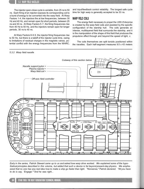
5.3 WARP FIELD NACELLESThe injector open-close cycle is variable, from 25 ns to 50ns. Each firing of an injector exposes its corresponding coil toa burst of energy to be converted into the warp field. At WarpFactors 1-4, the injectors fire at low frequencies, between 30Hz and 40 Hz, and remain open for short periods, between 25ns and 30 ns. At Warp Factors 5-7, the firing frequencies risefrom 40 Hz to 50 Hz, and the injectors remain open for longerperiods, 30 ns to 40 ns.At Warp Factors 8-9.9, the injector firing frequencies riseto 50 Hz, but there is a tailoff of the injector cycle time, owingto limitations of residual charges in the magnetic valves, potentialconflict with the energy frequencies from the M/ARC,and input/feedback control reliability. The longest safe cycletime for high warp is generally accepted to be 53 ns.WARP FIELD COILSThe energy field necessary to propel the USS Enterpriseis created by the warp field coils and assisted by the specificconfiguration of the <strong>star</strong>ship hull. The coils generate anintense, multilayered field that surrounds the <strong>star</strong>ship, and itis the manipulation of the shape of this field that produces thepropulsive effect through and beyond the speed of light, c.The coils themselves are split toroids positioned withinthe nacelles. Each half-segment measures 9.5 x 43 meters5.3.2 Warp field nacelleCutaway of this section belowNacelle support pylon •Plasma injector •Warp field coil •Off-axis field controllerCDCDooO\mi „ -hirxo)CD O CDC 3 O o o o O O o 9 o OEarly in the series, Patrick Stewart came up to us and asked how warp drive worked. We explained some of the hypotheticalprinciples described in this volume, but added that such a device is far beyond present-day physics. We emphasizedthat no one has any real idea how to make a ship go faster than light. "Nonsense," Patrick declared. "All you haveto do is say, 'Engage.'" And he was right...