franchise-star-trek-tng-technical-manual1
franchise-star-trek-tng-technical-manual1 franchise-star-trek-tng-technical-manual1
2.6 EMERGENCY PROCEDURES IN SIF/IDF FAILURE2.6 EMERGENCY PROCEDURES IN SIF/IDF FAILUREFailure of the structural integrity field (SIF) or the inertialdamping field (IDF) can have potentially catastrophic consequencesto the starship and to its crew. For this reason,multiple redundancy has been built into these systems, andemergency protocols have been devised to anticipate thepossibility of failure of one or more of these units.The Enterprise is dependent upon its structural integrityfield to maintain the spaceframe during the tremendousaccelerations encountered during impulse flight as well as thedifferential subspace field stresses experienced during warpflight. The inertial damping field also provides vital cushioningto the fragile crew during such maneuvers. Without suchprotection, the spacecraft and crew are unable to surviveaccelerations in excess of 30 m/sec 2 (approximately 3g)without serious structural damage to the spaceframe and severe— probably fatal — injury to the crew. By way of contrast,accelerations considerably in excess of 1,000g are not uncommonwhen under full impulse power. Warp flight operationsdo not produce direct acceleration stresses, but SIF/IDFprotection is needed because of the potential for warp field differentialstresses and local variations in inertial potential.Under Cruise Mode operating protocols, two field generatorsare active at all times, although one unit is sufficient toprovide adequate protection for both spacecraft and crewexcept during extreme maneuvers. In case of failure of onefield generator, a backup unit will automatically engage,keeping the number of active units at two. If a third unit isavailable to be placed in service, Cruise Mode rules allowoperations in progress to continue without interruption.remaining field generators is believed to be immediately imminent.The failure of all five field generators requires an immediateRed Alert status. The Commanding Officer is firstrequired to stabilize the situation, take steps to minimizepotential risk, and then to begin deceleration maneuvers.Severe operational limits are imposed on vehicle maneuvers.Immediate downwarping to sublight must be performed, exceptduring active combat situations. Such downwarping must bea simple field collapse maneuver; differential field maneuversare not permitted.Once the Commanding Officer or supervising OperationsManager has determined that further system failures areno longer an immediate threat, power conservation proceduresare initiated because of the possibility that the ship maybe unable to make a significant change in course or speed fora period of several months. Starfleet Command is notified forpossible assistance or rescue efforts.Until the arrival of assistance, the ship should maintainpower conservation procedures and perform the maximumdeceleration consistent with vehicle and crew safety. Rescueand salvage options include replacement of field generationcomponents, evacuation of crew to permit unprotected decelerationusing the ship's own engines or a tractor beam. Undercertain conditions, it is possible for a rescue vessel to projectan SIF/IDF onto the ship, although this is a difficult andextremely power-intensive procedure. A final option is theevacuation of the crew and abandonment of the spacecraft,although even this option should not preclude the possibilityof salvage at a later date.In the event of failure of two field generators, or in thecase where an additional backup cannot be brought on line,operating rules require a Yellow Alert status to be initiated,and the Commanding Officer is required to make a determinationwhether to allow primary or secondary mission operationsin progress to continue.In the event of failure of three or four field generators, regardlessof the availability of backup units, Yellow Alert statusmust be initiated and the vehicle must attempt to decelerateto an inertially safe condition, subject to sufficient generatorcapacity. If the spacecraft is presently at sublight speed, thatspeed must be reduced to the point where further decelerationcan be absorbed by minimal inertial damping and structuralintegrity capacity. If the spacecraft is traveling at warp, animmediate reduction to sublight must be initiated, subject tomaximum allowable subspace field differentials. Such downwarpingmust be a simple field collapse maneuver; differentialfield maneuvers are not permitted. Operating rules provide forexceptions during combat situations or when the failure of theWe assume that these operating protocols are somewhat conservative. In "Tin Man," the ever resourceful Geordi La Forgewas able to divert some power from the structural integrity field to keep the shields up. The computer warned that doing sowould compromise safety limits, but Geordi was obviously able to keep the ship together and the shields up.
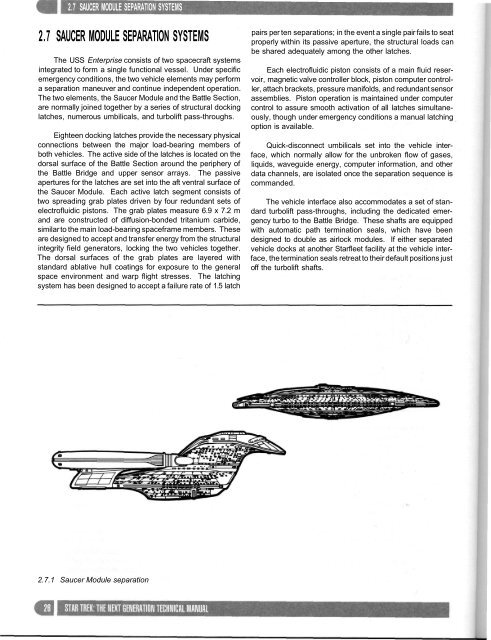
2.7 SAUCER MODULE SEPARATION SYSTEMS2.7 SAUCER MODULE SEPARATION SYSTEMSThe USS Enterprise consists of two spacecraft systemsintegrated to form a single functional vessel. Under specificemergency conditions, the two vehicle elements may performa separation maneuver and continue independent operation.The two elements, the Saucer Module and the Battle Section,are normally joined together by a series of structural dockinglatches, numerous umbilicals, and turbolift pass-throughs.Eighteen docking latches provide the necessary physicalconnections between the major load-bearing members ofboth vehicles. The active side of the latches is located on thedorsal surface of the Battle Section around the periphery ofthe Battle Bridge and upper sensor arrays. The passiveapertures for the latches are set into the aft ventral surface ofthe Saucer Module. Each active latch segment consists oftwo spreading grab plates driven by four redundant sets ofelectrofluidic pistons. The grab plates measure 6.9 x 7.2 mand are constructed of diffusion-bonded tritanium carbide,similar to the main load-bearing spaceframe members. Theseare designed to accept and transfer energy from the structuralintegrity field generators, locking the two vehicles together.The dorsal surfaces of the grab plates are layered withstandard ablative hull coatings for exposure to the generalspace environment and warp flight stresses. The latchingsystem has been designed to accept a failure rate of 1.5 latchpairs per ten separations; in the event a single pair fails to seatproperly within its passive aperture, the structural loads canbe shared adequately among the other latches.Each electrofluidic piston consists of a main fluid reservoir,magnetic valve controller block, piston computer controller,attach brackets, pressure manifolds, and redundant sensorassemblies. Piston operation is maintained under computercontrol to assure smooth activation of all latches simultaneously,though under emergency conditions a manual latchingoption is available.Quick-disconnect umbilicals set into the vehicle interface,which normally allow for the unbroken flow of gases,liquids, waveguide energy, computer information, and otherdata channels, are isolated once the separation sequence iscommanded.The vehicle interface also accommodates a set of standardturbolift pass-throughs, including the dedicated emergencyturbo to the Battle Bridge. These shafts are equippedwith automatic path termination seals, which have beendesigned to double as airlock modules. If either separatedvehicle docks at another Starfleet facility at the vehicle interface,the termination seals retreat to their default positions justoff the turbolift shafts.2.7.1 Saucer Module separation
- Page 2 and 3: CONTENTSINTRODUCTION BYGENE RODDENB
- Page 4 and 5: 1.1 MISSION OBJECTIVES FOR GALAXY C
- Page 6 and 7: 1.2 DESIGN LINEAGEENVIRONMENT/CREW
- Page 8 and 9: 1.3 GENERAL OVERVIEW1.3 GENERAL OVE
- Page 10 and 11: sionally to monitor their operation
- Page 12 and 13: Transporter emitter (typ.)Saucer Mo
- Page 14 and 15: Observation lounge •Main Shuttleb
- Page 16 and 17: 1.3.10 USS Enterprise forward dorsa
- Page 18 and 19: 1.4.2 Structural frame assembly at
- Page 20 and 21: 1.4 CONSTRUCTION CHRONOLOGYprogramm
- Page 22 and 23: 2.1 MAIN SKELETAL STRUCTURE2.1.2 St
- Page 24 and 25: The first group of two digits refer
- Page 26 and 27: 2.4 STRUCTURAL INTEGRITY FIELD SYST
- Page 30 and 31: 2.7 SAUCER MUOULE SEPARATIUN SYSTEM
- Page 32 and 33: 2.7 SAUCER MODULE SEPARATION SYSTEM
- Page 34 and 35: 3.1 MAIN BRIDGEmain viewer display
- Page 36 and 37: 3.2 BRIDGE OPERATIONS 3.3 BASIC CON
- Page 38 and 39: 3.4 FLIGHT CONTROL (CONN)3.4 FLIGHT
- Page 40 and 41: 3.4.3 Headings can be measured rela
- Page 42 and 43: 3.6 TACTICALThe Main Bridge station
- Page 44 and 45: necessary overriding ongoing scienc
- Page 46 and 47: 3.11 ENGINEERING3.11.1 Engineering
- Page 48 and 49: Pacific bottlenose dolphins, respec
- Page 50 and 51: 3.14 BATTLE BRIDGE 3.15 MAIN ENGINE
- Page 52 and 53: 4.0 COMPUTER SYSTEMS4.1 COMPUTER SY
- Page 54 and 55: 4.1 COMPUTER SYSTEM4.1.3 Optical da
- Page 56 and 57: PADD memory limitations and the rel
- Page 58 and 59: A subspace field of one thousand mi
- Page 60 and 61: 5.2 MATTER/ANTIMATTER REACTION ASSE
- Page 62 and 63: .Z HUM 11 tli/flhl I IMA 11 tii KtA
- Page 64 and 65: 5.2 MATTER/ANTIMATTER ¥highly comp
- Page 66 and 67: 5.3 WARP FIELD NACELLES5.3 WARP FIE
- Page 68 and 69: and is constructed from a core of d
- Page 70 and 71: 5.4 ANTIMATTER STORAGE AND TRANSFER
- Page 72 and 73: 5.5 WARP PROPULSION SYSTEM FUEL SUP
- Page 74 and 75: compact set of six coils designed t
- Page 76 and 77: iT.ll.Mlii iiiirm 1'iirninil nunNUU
2.7 SAUCER MODULE SEPARATION SYSTEMS2.7 SAUCER MODULE SEPARATION SYSTEMSThe USS Enterprise consists of two spacecraft systemsintegrated to form a single functional vessel. Under specificemergency conditions, the two vehicle elements may performa separation maneuver and continue independent operation.The two elements, the Saucer Module and the Battle Section,are normally joined together by a series of structural dockinglatches, numerous umbilicals, and turbolift pass-throughs.Eighteen docking latches provide the necessary physicalconnections between the major load-bearing members ofboth vehicles. The active side of the latches is located on thedorsal surface of the Battle Section around the periphery ofthe Battle Bridge and upper sensor arrays. The passiveapertures for the latches are set into the aft ventral surface ofthe Saucer Module. Each active latch segment consists oftwo spreading grab plates driven by four redundant sets ofelectrofluidic pistons. The grab plates measure 6.9 x 7.2 mand are constructed of diffusion-bonded tritanium carbide,similar to the main load-bearing spaceframe members. Theseare designed to accept and transfer energy from the structuralintegrity field generators, locking the two vehicles together.The dorsal surfaces of the grab plates are layered withstandard ablative hull coatings for exposure to the generalspace environment and warp flight stresses. The latchingsystem has been designed to accept a failure rate of 1.5 latchpairs per ten separations; in the event a single pair fails to seatproperly within its passive aperture, the structural loads canbe shared adequately among the other latches.Each electrofluidic piston consists of a main fluid reservoir,magnetic valve controller block, piston computer controller,attach brackets, pressure manifolds, and redundant sensorassemblies. Piston operation is maintained under computercontrol to assure smooth activation of all latches simultaneously,though under emergency conditions a manual latchingoption is available.Quick-disconnect umbilicals set into the vehicle interface,which normally allow for the unbroken flow of gases,liquids, waveguide energy, computer information, and otherdata channels, are isolated once the separation sequence iscommanded.The vehicle interface also accommodates a set of standardturbolift pass-throughs, including the dedicated emergencyturbo to the Battle Bridge. These shafts are equippedwith automatic path termination seals, which have beendesigned to double as airlock modules. If either separatedvehicle docks at another Starfleet facility at the vehicle interface,the termination seals retreat to their default positions justoff the turbolift shafts.2.7.1 Saucer Module separation


