VE4MA and Chaparral feeds with Septum polarizers - W1GHZ
VE4MA and Chaparral feeds with Septum polarizers - W1GHZ
VE4MA and Chaparral feeds with Septum polarizers - W1GHZ

Create successful ePaper yourself
Turn your PDF publications into a flip-book with our unique Google optimized e-Paper software.
<strong>VE4MA</strong> <strong>and</strong> <strong>Chaparral</strong> <strong>feeds</strong> <strong>with</strong> <strong>Septum</strong> PolarizersPaul Wade <strong>W1GHZ</strong> ©2006 w1ghz@arrl.netmeasurements byTommy Henderson WD5AGO wd5ago@hotmail.comThis started out to be a simple project – optimize the <strong>VE4MA</strong> feedhorn 1 <strong>with</strong> a septumpolarizer 2 for circular polarization. Some unexpected results have led to a larger analysis<strong>with</strong> conclusions that may differ from the prevailing wisdom, but have been verified bymeasurements made by WD5AGO. Some improved feedhorn variations are alsodescribed, which show some of the highest calculated <strong>and</strong> measured efficiencies to datefor a prime-focus dish.What we often call a “feedhorn” includes several separate elements: an antenna whichshapes the beam for improved dish illumination, a waveguide section (round, square, orrectangular), perhaps a circular polarizer, <strong>and</strong> an excitation region (waveguide, probetransition to coax, or other transition). While these elements may interact, each has aseparate function <strong>and</strong> may be analyzed independently. It is not necessary to exactlyreplicate all the dimensions from end-to-end, but it would be foolhardy to make changes<strong>with</strong>out considering possible interactions.Thus, we will separate the following elements for examination:• <strong>VE4MA</strong> horn• <strong>Chaparral</strong>-style horn• <strong>Septum</strong> polarizer in circular waveguide• <strong>VE4MA</strong> <strong>and</strong> <strong>Chaparral</strong> horns <strong>with</strong> septum polarizerThe excitation is a separate problem; all analysis here, using Ansoft HFSS software 3 , willuse single-mode waveguide excitation. Probe transitions in circular waveguide werestudied in a previous paper 4 , so probes will not be included here. The probe is not part ofthe antenna. The only complication which might be added by probe excitation would beadditional waveguide modes; if the waveguide section preceding the horn is sufficientlylong, then the additional modes will not reach the horn <strong>and</strong> thus not affect the radiationpattern. Single-mode excitation eliminates this potential complication from the analysis.Dish illumination reviewThe ideal illumination for a parabolic dish antenna would provide uniform energy overthe reflector surface, <strong>with</strong> no spillover energy missing the dish. Real feed antennas donot provide this ideal distribution. Figure 1, from the <strong>W1GHZ</strong> Microwave Antenna Book– Online 5 , shows the desired illumination vs. a typical (idealized) feed pattern. Thetypical pattern energy decreases from the central peak, while the desired pattern energyincreases toward the edges to compensate for space attenuation – the edge of the dish isfarther from the feed than the center of the dish.
The typical feed pattern also has spillover energy which misses the reflector, <strong>and</strong> real<strong>feeds</strong> have sidelobes <strong>and</strong> backlobes which also waste energy. For many <strong>feeds</strong>, it has beenfound that the tradeoff between illumination <strong>and</strong> spillover yielding best efficiency occurswhen the illumination (not the feed pattern – we must account for space attenuation) isabout 10 dB down at the edge of the dish. This 10 dB feed taper is just a rule-of-thumb;for accurate analysis, we use pattern integration, calculating the efficiency for the fullthree-dimensional feed pattern (in practice, for well behaved <strong>feeds</strong>, only a few cutsthrough the 3D pattern are necessary).Note: all efficiency calculations are for an arbitrary 20λ dish diameter <strong>and</strong> a 1.7λ feeddiameter, or a constant blockage ratio of 0.085, so that we are comparing apples toapples. For small dishes, the actual blockage is more significant <strong>and</strong> efficiency should berecalculated.<strong>VE4MA</strong> FeedThe <strong>VE4MA</strong> feed 1 is based on a paper by Kumar 6 . This horn, which adds a single ringaround a circular waveguide (Figure 2), has patterns shown in both papers which are notmaximum at the center, but rather increase somewhat like our desired feed beforetapering off like a typical feed – see Figure 1. Thus, the pattern, shown in Figure 3, tendsto be more like the desired illumination, <strong>and</strong> provides somewhat better efficiency than atypical feed, for instance, the open circular waveguide (“coffee-can feed”) <strong>with</strong>out thering. The pattern <strong>and</strong> efficiency plots for open circular waveguide <strong>feeds</strong> are shown inFigure 4; efficiency is lower than the <strong>VE4MA</strong> feed for all but the largest diameters, <strong>and</strong>those larger diameters are large enough to propagate additional modes which will degradethe performance.
Feed Radiation PatternDish diameter = 20 λOriginal <strong>VE4MA</strong> Feed 0.77λ horn diameterRing 0.50λ wide x 0.50λ deep, 0.15λ behind rimFigure 30 dB -10 -20 -30E-planeH-planeFeed diameter = 1.7 λFeed Phase Angle9067.54522.50-22.5-45-67.5-90E-planeH-plane0 10 20 30 40 50 60 70 80 90Rotation Angle around specifiedPhase Center = 0.014 λ beyond apertureParabolic Dish Efficiency %9080706050403020MAX Possible Efficiency <strong>with</strong> Phase errorMAX Efficiency <strong>with</strong>out phase error AFTER LOSSES:REAL WORLD at least 15% lowerIlluminationSpilloverFeed Blockage1 dB2 dB3 dB4 dB5 dB6 dB7 dB8 dB100.250.3 0.4 0.5 0.6 0.7 0.8 0.9Parabolic Dish f/D<strong>W1GHZ</strong> 2006
Feed Radiation Pattern0 dB -10 -20 -30Dish diameter = 20 λCylindrical waveguide <strong>feeds</strong>, no ring"Coffee-can Feed"Figure 4E-planeH-planeFeed diameters listedFeed Phase Angle9067.54522.50-22.5-45-67.5-90E-planeH-plane0 10 20 30 40 50 60 70 80 90Rotation Angle around specifiedPhase Center = 0 λ beyond apertureParabolic Dish Efficiency %9080706050403020MAX Possible Efficiency <strong>with</strong> Phase errorREAL WORLD at least 15% lower0.635 λ diameter0.71 λ diameter0.77 λ diameter0.86 λ diameter0.96 λ diameter1 dB2 dB3 dB4 dB5 dB6 dB7 dB8 dB100.250.3 0.4 0.5 0.6 0.7 0.8 0.9Parabolic Dish f/D<strong>W1GHZ</strong> 2006
It was suggested by Kumar that a ring dimension, ½λ wide x ½λ deep, forms a resonantstructure which creates the improved pattern. Therefore, hams have carefully duplicatedthe dimensions published by Barry, <strong>VE4MA</strong>, for this feed, <strong>with</strong> very good results. Onereason for the popularity of this feed is that it works well for conventional dishes over awide range of f/D; the feed is optimized by the position of the ring <strong>with</strong> respect to the rimof the central horn.If the ring is resonant, there should be a clear peak in performance <strong>with</strong> dimensionswhich are resonant. However, when I first varied the dimensions, the only slight peakwas <strong>with</strong> one ring position, <strong>with</strong> the ring 0.15λ behind the rim of the central horn.Varying the other dimensions, I could find no peak at all – either there is no peak, or it isso sharp that we have no hope of duplicating it. The performance was nearly identicalover a broad range of dimensions, suggesting that we could make better use of availablematerials. Performance was slightly better <strong>with</strong> a range of smaller ring dimensions,which would have the additional benefit of reduced blockage. The improvement <strong>with</strong> asmaller ring could be significant for the smaller dishes used by many hams.<strong>VE4MA</strong> feed - 0.5 x 0.5 lambda ring800.5Dish Efficiency (%)75700.4f/D0.3Horn Diameter0.77 eff0.71 eff0.77 f/D0.71 f/D650.2-0.05 0 0.05 0.1 0.15 0.2 0.25Ring position - wavelengths behind rimFigure 5. <strong>VE4MA</strong> feed – horn diameter comparisonThe <strong>VE4MA</strong> dimensions specify a circular waveguide horn diameter of 0.77λ. Myprevious work <strong>with</strong> the OK1DFC septum found that the septum worked best <strong>with</strong> a 0.71λdiameter circular waveguide, so most of the variations in ring dimensions I tried were<strong>with</strong> the smaller diameter so that they would also work <strong>with</strong> a septum polarizer.However, comparing feedhorns <strong>with</strong> the same ring dimensions on the two differentdiameter horns showed little difference, as illustrated in Figure 5 for the original ringdimensions of 0.5λ wide <strong>and</strong> 0.5λ deep, <strong>and</strong> for a smaller ring of 0.35λ wide <strong>and</strong> 0.35λdeep in Figure 6 below. The original 0.77λ might have a slight advantage, but the twodiameters give comparable performance, <strong>and</strong> sizes in between would probably work justas well. So, for linear polarization, any available material is this diameter range would begood.
<strong>VE4MA</strong> feed - 0.35 x 0.35 lambda ring800.5Dish Efficiency (%)75700.40.3f/D0.77 eff0.71 eff0.77 f/D0.71 f/D650.2-0.05 0 0.05 0.1 0.15 0.2 0.25 0.3 0.35Ring position - wavelengths behind rimFigure 6Later, I tried much larger <strong>and</strong> deeper rings, <strong>and</strong> did find a peak <strong>with</strong> significantly higherefficiency (nearly 80%), for a ring <strong>with</strong> dimensions around 0.6 to 0.65λ wide <strong>and</strong> 0.4 to0.45λ deep. The peak extends to another range of ring dimensions around 0.65 to 0.75λwide <strong>and</strong> 0.3 to 0.4λ deep. I chose ring dimensions of 0.6λ wide <strong>and</strong> 0.45λ deep to benear the center of this peak. Figure 7 is the efficiency plot for this larger horn, which weshall call the “Super <strong>VE4MA</strong>.” For larger dishes, 20λ <strong>and</strong> up, this may be a winner.WD5AGO has built <strong>and</strong> measured a horn <strong>with</strong> a ring 0.6λ wide <strong>and</strong> 0.45λ deep, <strong>with</strong> thepredicted improvement in sun noise – see the measurement results in Appendix A.The improved feedhorn does show the desirable distinctive dip in the center of theradiation pattern, shown in the 3D plot in Figure 8. We might conclude that Kumar wason the right track, but lacked the software to refine the dimensions.Figure 8. 3D pattern for Super <strong>VE4MA</strong> feedThe larger ring provides higher efficiency <strong>with</strong> horns of both 0.71λ <strong>and</strong> 0.77λ diameter,as shown in Figure 9. The downside of the larger ring is that the improved efficiency isonly useful for a limited range of f/D, roughly 0.35 to 0.45.
Feed Radiation PatternDish diameter = 20 λSuper <strong>VE4MA</strong> 0.71λ horn diameterRing 0.60λ wide x 0.45λ deep, 0.15λ behind rimFigure 70 dB -10 -20 -30E-planeH-planeFeed diameter = 1.7 λFeed Phase Angle9067.54522.50-22.5-45-67.5-90E-planeH-plane0 10 20 30 40 50 60 70 80 90Rotation Angle around specifiedPhase Center = 0.14 λ inside apertureParabolic Dish Efficiency %9080706050403020MAX Possible Efficiency <strong>with</strong> Phase errorMAX Efficiency <strong>with</strong>out phase error AFTER LOSSES:REAL WORLD at least 15% lowerIlluminationSpilloverFeed Blockage1 dB2 dB3 dB4 dB5 dB6 dB7 dB8 dB100.250.3 0.4 0.5 0.6 0.7 0.8 0.9Parabolic Dish f/D<strong>W1GHZ</strong> 2006
Super <strong>VE4MA</strong> feed - 0.60 x 0.45 lambda ring800.5Dish Efficiency (%)75700.40.3f/D0.77 eff0.71 eff0.77 f/D0.71 f/D650.2-0.05 0 0.05 0.1 0.15 0.2 0.25 0.3 0.35Ring position - wavelengths behind rimFigure 9. Super <strong>VE4MA</strong> feed – horn diameter comparisonSome of the smaller versions provide good performance, as good as or better than theoriginal dimensions, over a wider range of f/D. Some promising combinations include aring 0.35λ wide <strong>and</strong> 0.35λ deep in Figure 6 above, a ring 0.4λ wide <strong>and</strong> 0.3λ deep shownin Figure 10, <strong>and</strong> a ring 0.25λ wide <strong>and</strong> 0.25λ deep shown in Figure 11. The last oneseems particularly attractive for very small dishes, since the blockage is much less thanthe original dimensions while the efficiency is as good or better.<strong>VE4MA</strong> 0.71dia, Ring 0.4 wide x 0.3 deepDish Efficiency(%)807570650.50.4f/D0.30.2Efficiencyf/D0 0.1 0.2 0.3 0.4Ring position - wavelengths behind rimFigure 10<strong>VE4MA</strong> 0.71 dia, Ring 0.25 wide x 0.25 deepDishEfficiency (5)807570650.50.4f/D0.30.2Efficiencyf/D0 0.1 0.2 0.3 0.4Ring position - wavelengths behind rimFigure 11
The smallest ring was suggested by CT1DMK, 0.12λ wide <strong>and</strong> 0.26λ deep. Figure 12shows that it is not quite as good as the others, but not significantly worse.<strong>VE4MA</strong> 0.71dia, Ring 0.12 wide x 0.26 deepDish Efficiency(%)80750.50.4f/D700.3650.20 0.1 0.2 0.3 0.4Ring position - wavelengths behind rimEfficiencyf/DFigure 12Rather than bury us <strong>with</strong> numbers at this point, I will include all the simulation data inAppendix B. A few of the most promising versions are compared in Figures 13 <strong>and</strong> 14,but perusal of the appendix will suggest that most combinations of ring width <strong>and</strong> depthwill work pretty well, so a size that can be made from available materials can be foundfor most applications.<strong>VE4MA</strong> feed - ring variationsDish Efficiency (%)807876747270686664-0.1 0 0.1 0.2 0.3 0.4 0.5Ring position -wavelengths behind rimRing - wavelengthsW0.5,D0.5W0.35,D0.35W0.4,D0.25W0.4,D0.3W0.25,D0.25W0.12,D0.26W0.2,D0.33W0.6,D0.45Figure 13
<strong>VE4MA</strong> feed - ring variations0.50.450.4f/D0.350.30.25-0.1 0 0.1 0.2 0.3 0.4 0.5W0.5,D0.5W0.35,D0.35W0.4,D0.25W0.4,D0.3W0.25,D0.25W0.12,D0.26W0.2,D0.33W0.6,D0.45Ring position -wavelengths behind rimFigure 14When we look at a wide range of ring sizes in Figure 15, we see that there is a range ofring sizes that does not work well: widths around 0.55λ wide <strong>with</strong> depths less than about0.5λ provide low efficiency. This may be the other side of the resonance. Appendix Bprobably shows all the details more clearly.Dish Efficiency (%)80787674727068666462<strong>VE4MA</strong> Feed - Ring variations600.25 0.3 0.35 0.4 0.45 0.5 0.55 0.6 0.65 0.7Ring width - WavelengthsFigure 15Ring Depth0.650.60.550.50.450.40.350.30.25
Figure 16Also worth noting are the radiation patterns produced by these horns as the ring positionis varied. With the ring forward, flush <strong>with</strong> the rim of the circular waveguide at theaperture, the patterns are similar to the typical feed in Figure 1. An example of a 3Dpattern is shown in Figure 16, <strong>and</strong> the efficiency plot, Figure 17, shows that this positionis best for a dish <strong>with</strong> f/D around 0.45 to 0.5. As the ring is moved back, the patternbroadens <strong>with</strong> the maximum moving away from the center for improved efficiency – thisis more pronounced in the E-plane. Figure 18 is a 3D example of this pattern shape, forthe original <strong>VE4MA</strong> dimensions. The efficiency plot for this pattern in Figure 3 showsthat moving the ring back is better for deep dishes, <strong>with</strong> f/D as low as 0.3. The Super<strong>VE4MA</strong> pattern in Figures 7 <strong>and</strong> 8 is much more axisymmetrical. As the ring is movedback, the back lobes become stronger, probably reducing efficiency slightly, but the ringposition seems to have a stronger effect on efficiency than on optimum f/D. Therefore,we may choose the ring dimensions to utilize available materials, <strong>and</strong> adjust the ringposition for best efficiency, starting <strong>with</strong> the data in Appendix B <strong>and</strong> optimizing it usingsun noise measurements.
Feed Radiation Pattern0 dB -10 -20 -30Dish diameter = 20 λSmall <strong>VE4MA</strong> Feed 0.71λ horn diameterRing 0.40λ wide x 0.30λ deep, flush <strong>with</strong> rimFigure 17E-planeH-planeFeed diameter = 1.7 λFeed Phase Angle9067.54522.50-22.5-45-67.5-90E-planeH-plane0 10 20 30 40 50 60 70 80 90Rotation Angle around specifiedPhase Center = 0.02 λ beyond apertureParabolic Dish Efficiency %9080706050403020MAX Possible Efficiency <strong>with</strong> Phase errorMAX Efficiency <strong>with</strong>out phase error AFTER LOSSES:REAL WORLD at least 15% lowerIlluminationSpilloverFeed Blockage1 dB2 dB3 dB4 dB5 dB6 dB7 dB8 dB100.250.3 0.4 0.5 0.6 0.7 0.8 0.9Parabolic Dish f/D<strong>W1GHZ</strong> 2006
Figure 18Phase CenterThe phase center for all variations of the <strong>VE4MA</strong> feed is roughly at the center of theaperture, but varies a bit <strong>with</strong> different ring sizes <strong>and</strong> positions. The total variation isonly quarter-wavelength or so, but a ¼λ error in axial position can lose a dB of gain,turning a good feed into a mediocre one. Therefore, we should consult Appendix B forthe calculated phase center for each combination, followed by sun noise measurementsfor final adjustment.
<strong>Chaparral</strong>-style <strong>feeds</strong>The <strong>Chaparral</strong>-style feed (<strong>Chaparral</strong> Communications makes them for satellite TV) hasmultiple smaller rings around the circular waveguide. The original description was apaper by Wohlleben 7 , <strong>and</strong> Tay Howard, W6HD, was involved in the commercialdevelopment for <strong>Chaparral</strong>.The multiple rings, typically slightly more than ¼λ deep <strong>and</strong> spaced less than ¼λ, createwhat electromagnetics professionals call a “soft” surface – one that reflects energy like asurface but does not conduct surface currents, thus reducing the edge currents thatgenerate sidelobes. Adding the additional variable, multiple rings, to the horn makes asearch for an optimum combination prohibitively large, so I limited analysis to a fewcombinations suggested by WD5AGO. Then I added a few variations to attempt tounderst<strong>and</strong> the effect of the multiple rings.The first version has three rings, each 0.17λ wide <strong>and</strong> 0.3λ deep. The total width of thethree rings is 0.51λ, almost exactly the same as the original <strong>VE4MA</strong> ring, so there is noblockage penalty for the additional rings; both have a total shadow 1.7λ in diameter. Theperformance, summarized in Figure 19, shows higher efficiency than the original<strong>VE4MA</strong>, particularly for deeper dishes <strong>with</strong> f/D in the 0.3 to 0.4 range.<strong>Chaparral</strong> 0.71horn diameter3 Rings 0.17 wide x 0.30 deepDish Efficiency (%)807570650 0.1 0.2 0.3 0.40.50.4f/D0.30.2Efficiencyf/DRing position -wavelengths behind rimFigure 19Another version has three rings, each 0.20λ wide <strong>and</strong> 0.33λ deep. The total width of0.60λ adds slightly more blockage, 1.9λ in diameter, but the calculated efficiency is a bithigher, so it is worth considering for all but the smallest dishes. The super-<strong>VE4MA</strong> <strong>with</strong>the same blockage has even higher efficiency, but over a smaller range of f/D. Figure 20compares the two <strong>Chaparral</strong> versions <strong>with</strong> the two <strong>VE4MA</strong> versions, original <strong>and</strong> Super –the improvements should be apparent.
<strong>Chaparral</strong> 3-ring vs <strong>VE4MA</strong>0.71 lambda horn diameter, equal total blockageDish Efficiency (%)807570650 0.1 0.2 0.3 0.4Ring position -wavelengths behind rim<strong>Chaparral</strong> 1.7lambda<strong>VE4MA</strong> 1.7 lambda<strong>Chaparral</strong> 1.9lambda<strong>VE4MA</strong> 1.9 lambdaFigure 20To see if the additional rings were beneficial, I tried versions <strong>with</strong> one, two, three, <strong>and</strong>four rings, each ring 0.20λ wide <strong>and</strong> 0.33λ deep. Figure 21 below shows that eachadditional ring increases dish efficiency, but it looks like the fourth ring is yieldingdiminishing returns.<strong>Chaparral</strong> 0.71 horn diameterRings 0.2 wide x 0.33 deep<strong>Chaparral</strong> 0.71 horn diameterRings 0.2 w ide x 0.33 deepDish Efficiency (% )807570650 0.1 0.2 0.3 0.4Four ringsThree ringsTw o ringsOne ringBest f/D0.50.40.30.20 0.1 0.2 0.3 0.4Ring position - wavelengths behind rimRing position - wavelengths behind rimFigure 21Is the increase in efficiency <strong>with</strong> more rings due to the number of rings or the larger size?To test this question, I tried two additional variants <strong>with</strong> the same overall width, 0.60λ, asthe three ring version above: two rings, each 0.30λ wide, <strong>and</strong> four rings, each 0.15λ wide.Figure 22 suggests that that two or three rings are about equal, <strong>with</strong> excellent efficiency,but adding more rings, closely spaced, has no benefit. Efficiency is not quite as high asthe super-<strong>VE4MA</strong> <strong>with</strong> the same blockage, but the <strong>Chaparral</strong> is better for deep dishes.
<strong>Chaparral</strong> vs super <strong>VE4MA</strong>0.71lambda horn diameter, 1.9 lambda total blockage80Dish Efficiency (%)7570650 0.1 0.2 0.3 0.4 0.54 ring 0.15 x 0.333 ring 0.20 x 0.332 ring 0.30 x 0.33<strong>VE4MA</strong> 0.6 x 0.45Ring position - wavelengths behind rimFigure 22The radiation patterns from the <strong>Chaparral</strong>-style <strong>feeds</strong> do not demonstrate the large dip inthe center that seems to provide improved efficiency for the best <strong>VE4MA</strong> variations. Theadditional rings seem to simply reduce radiation in undesired lobes <strong>and</strong> put more evenenergy over a wide angle on the reflector, as seen in Figure 23, a 3D pattern for the feedin Figure 22 <strong>with</strong> 3 rings 0.20λ wide <strong>and</strong> 0.33λ deep, 0.25λ behind the rim. The result isthe high efficiency plotted in Figure 24.Figure 23. 3D pattern for <strong>Chaparral</strong> feed <strong>with</strong> 3 rings 0.20λ wide <strong>and</strong> 0.33λ deep, back 0.25λThe advantage of the <strong>Chaparral</strong>-style <strong>feeds</strong> over the simpler <strong>VE4MA</strong> is high efficiencyover a wider range of f/D, <strong>and</strong> probably over a broader b<strong>and</strong>width. The b<strong>and</strong>width wasnot investigated since all amateur operation is in relatively small b<strong>and</strong>widths.
Feed Radiation Pattern<strong>Chaparral</strong> Feed 0.71λ horn diameter3 Rings 0.20λ wide x 0.33λ deep, 0.25λ behind rimFigure 240 dB -10 -20 -30Dish diameter = 20 λE-planeH-planeFeed diameter = 1.7 λFeed Phase Angle9067.54522.50-22.5-45-67.5-90E-planeH-plane0 10 20 30 40 50 60 70 80 90Rotation Angle around specifiedPhase Center = 0.11 λ inside apertureParabolic Dish Efficiency %9080706050403020MAX Possible Efficiency <strong>with</strong> Phase errorMAX Efficiency <strong>with</strong>out phase error AFTER LOSSES:REAL WORLD at least 15% lowerIlluminationSpilloverFeed Blockage1 dB2 dB3 dB4 dB5 dB6 dB7 dB8 dB100.250.3 0.4 0.5 0.6 0.7 0.8 0.9Parabolic Dish f/D<strong>W1GHZ</strong> 2006
<strong>Septum</strong> PolarizerAll septum <strong>polarizers</strong> to date are based on one set of published dimension in squarewaveguide, from a paper by Chen <strong>and</strong> Ts<strong>and</strong>oulas 8 , <strong>and</strong> adapted for ham use byOK1DFC 2 . Using the open-ended square waveguide as a feed provides reasonably goodperformance, about 70% efficiency for an f/D around 0.37, shown in Figure 25, but thereis no way to make it adjustable for different f/D. The heavy lines in the Feed RadiationPattern are RHCP, while the light broken line is for all polarizations – the rear lobes arenot well polarized, but it does not matter since this is all spillover.I previously 9 found that the same septum dimensions for square waveguide could bescaled to provide good circular polarization in circular waveguide of 0.71λ diameter 8 .With the septum, circularly-polarized performance of an open-ended circular waveguideas a feed, shown in Figure 26, is comparable to linear polarization, in Figure 4, but not asgood as the square version. However, the round version of the septum polarizer iscompatible <strong>with</strong> the <strong>VE4MA</strong> <strong>and</strong> <strong>Chaparral</strong> <strong>feeds</strong>.I first made some attempts to improve on the septum in circular waveguide, but <strong>with</strong>confusing results. I finally realized that the isolation is seriously affected by the horn –any mismatch at the aperture (typically 10 to 15 dB return loss), between the horn <strong>and</strong>free space, is reflected back to the other port as reduced isolation between the twopolarizations. Feeding a prime focus dish, the problem is even worse: reflection from theshadowed portion of the reflector, perhaps 15 dB down, has reversed polarity so thatisolation is compromised. Therefore, attempts to achieve high isolation in the feed arerather futile!We can demonstrate the effect of any mismatch in software, by placing a “PerfectlyMatched Layer” over the aperture, so that there is no reflection. Of course, this layeronly exists in software. In Figure 27 below, isolation <strong>and</strong> return loss of the open-endedwaveguide, on the left, is compared <strong>with</strong> the perfectly-matched aperture on the right. Thematched aperture shows better isolation over a wider frequency range. More important,changes to the aperture, by adding rings or horns, will affect the isolation.
Feed Radiation Pattern0 dB -10 -20 -30Dish diameter = 20 λOK1DFC square septum feedFigure 25E-planeH-planeFeed diameter = 0.63 λFeed Phase Angle90E-plane67.5H-plane4522.50-22.5-45-67.5-900 10 20 30 40 50 60 70 80 90Rotation Angle around specifiedPhase Center = 0 λ beyond apertureParabolic Dish Efficiency %9080706050403020MAX Possible Efficiency <strong>with</strong>out XPOL or Phase errorMAX Possible Efficiency <strong>with</strong> XPOL loss & Phase errorMAX Efficiency <strong>with</strong> phase error ONLY AFTER LOSSES:REAL WORLD at least 15% lowerIlluminationSpilloverFeed Blockage1 dB2 dB3 dB4 dB5 dB6 dB7 dB8 dB100.250.3 0.4 0.5 0.6 0.7 0.8 0.9Parabolic Dish f/D<strong>W1GHZ</strong> 1998, 2006
Feed Radiation PatternCircular septum feed 0.71λ diameter, no ringFigure 26E-plane0 dB -10 -20 -30H-planeDish diameter = 20 λ Feed diameter = 1.7 λFeed Phase Angle90E-plane67.5H-plane4522.50-22.5-45-67.5-900 10 20 30 40 50 60 70 80 90Rotation Angle around specifiedPhase Center = 0 λ beyond apertureParabolic Dish Efficiency %9080706050403020MAX Possible Efficiency <strong>with</strong>out XPOL or Phase errorMAX Possible Efficiency <strong>with</strong> XPOL loss & Phase errorMAX Efficiency <strong>with</strong> phase error ONLY AFTER LOSSES:REAL WORLD at least 15% lowerIlluminationSpilloverFeed Blockage1 dB2 dB3 dB4 dB5 dB6 dB7 dB8 dB100.250.3 0.4 0.5 0.6 0.7 0.8 0.9Parabolic Dish f/D<strong>W1GHZ</strong> 1998, 2006
Another paper <strong>with</strong> septum dimensions, by Bornemann <strong>and</strong> Labay 10 , suggest that athicker septum may improve isolation. A few quick trials suggest this may be true insquare waveguide, which could be useful for higher-frequency septums, where machiningthe whole polarizer from solid metal might be easier than assembly of small parts. Amore important observation was that septum dimensions <strong>and</strong> thickness had no effect onantenna pattern or performance. Also, WD5AGO tested a thicker septum in circularwaveguide <strong>with</strong> no difference in antenna performance. Therefore, any conclusions wemight reach <strong>with</strong> one septum should apply to any better future septums.<strong>VE4MA</strong> horn <strong>with</strong> septum polarizerSeveral variations of the <strong>VE4MA</strong> horn were also simulated <strong>with</strong> a septum polarizer. Theresults for the original ring dimensions, 0.5λ wide <strong>and</strong> 0.5λ deep, are summarized inFigure 28, <strong>and</strong> compared <strong>with</strong> linear polarization. Efficiencies are similar, but veryslightly lower for circular polarization, <strong>and</strong> the best f/D at each ring position isunchanged.Original <strong>VE4MA</strong> feedRing 0.50 wide x 0.50 deep800.5Dish Efficiency (%)75700.4f/D0.3<strong>Septum</strong> EffLinear Eff<strong>Septum</strong> f/DLinear f/D65-0.05 0.05 0.15 0.25 0.35Ring position -wavelengths behind rim0.2Figure 28. Original <strong>VE4MA</strong> feed, circular <strong>and</strong> linear polarization
Small <strong>VE4MA</strong> feedRing 0.4 wide x 0.25 deep800.5Dish Efficiency75700.40.3<strong>Septum</strong> EffLinear Eff<strong>Septum</strong> f/DLinear f/D650.20 0.1 0.2 0.3 0.4 0.5Ring position - wavelengths behind rimFigure 29Two of the versions <strong>with</strong> smaller rings are compared in Figure 29, <strong>with</strong> a ring 0.4λ wide<strong>and</strong> 0.25λ deep, <strong>and</strong> Figure 30, <strong>with</strong> a ring 0.35λ wide <strong>and</strong> 0.35λ deep. For both of thesecases, the efficiencies for f/D greater than about 0.35 for linear <strong>and</strong> circular polarizationare about equal. However, for deep dishes, <strong>with</strong> f/D < 0.35, efficiency improves <strong>with</strong>linear polarization <strong>and</strong> decreases <strong>with</strong> circular polarization. Again, the best f/D at eachring position, as well as the phase center, not shown, do not change <strong>with</strong> polarization.Small <strong>VE4MA</strong> feedRing 0.35 wide x 0.35 deep800.5Dish Efficiency(%)7570650.4f/D0.30.20 0.1 0.2 0.3 0.4<strong>Septum</strong> EffLinear Eff<strong>Septum</strong> f/DLinear f/DRing position - wavelengths behind rimFigure 30The version <strong>with</strong> the 0.35λ wide <strong>and</strong> 0.35λ deep ring was also examined over a range offrequency, summarized in Figure 31. Efficiency was good from 2.3 to 2.6 GHz, betterthan 10% b<strong>and</strong>width, while isolation peaked at 2.3 GHz.
<strong>VE4MA</strong> <strong>Septum</strong> vs FrequencyRing 0.35 wide x 0.35 deepDish Efficiency(%)807570650.50.4f/D0.30.22 2.1 2.2 2.3 2.4 2.5 2.6Frequency (GHz)Efficiencyf/DFigure 31The Super <strong>VE4MA</strong> works <strong>with</strong> well <strong>with</strong> a septum feed, showing efficiency comparableto linear polarization at all ring positions in Figure 32, but the best f/D range is still fairlylimited, around 0.35 to 0.45. The 3D radiation pattern in Figure 33 shows the dip atboresight like our desired illumination in Figure 1.Super <strong>VE4MA</strong> feedRing 0.6 wide x 0.45 deepDish Efficiency(%)807570650.20 0.1 0.2 0.3 0.4Ring position -wavelengths behind rimFigure 320.50.4f/D0.3<strong>Septum</strong> EffLinear Eff<strong>Septum</strong> f/DLinear f/D
Figure 33. Super <strong>VE4MA</strong> feed <strong>with</strong> <strong>Septum</strong> Polarizer, 3D patternThe apparent cause of the poorer CP performance at small f/D is that the circularity is notgood at wide illumination angles (theta). Frequently, the circularity of a CP antenna isgiven for the boresight, but this is not important for a feed – the feed boresight is usuallyblocked. A CP feed must provide good circular polarization over the whole reflector.Usually, circularity is quantified by the axial ratio, the ratio of the horizontal <strong>and</strong> verticalcomponents of the circular polarization. For perfect circular polarization, the componentsare equal <strong>and</strong> the axial ratio is 0dB. The larger the axial ratio, the more elliptical is thecircular polarization. For perfect linear polarization, the axial ratio is infinite.Measurement of the axial ratio over the whole pattern would be really difficult, but insimulation, it is just more numbers to crunch. For the version in Figure 30, <strong>with</strong> a ring0.35λ wide <strong>and</strong> 0.35λ deep, the axial ratios are plotted in Figure 34 <strong>with</strong> the ring flush<strong>with</strong> the rim, providing good linear <strong>and</strong> CP efficiency for an f/D of 0.49, <strong>and</strong> in Figure 35<strong>with</strong> the ring pulled back 0.3λ, providing good linear efficiency for an f/D of 0.31, but afew points lower (68 %, by no means terrible) for CP. In Figure 34, the axial ratio isbetter than 0.6 dB over an illumination half-angle of 60°, which covers the wholereflector, while in Figure 35, the axial ratio is better than 1 dB over only about 12° <strong>and</strong>falls off to 5 dB at the edge of the reflector, which subtends an illumination half-angle of75° for f/D = 0.31.
Figure 34Figures 34 <strong>and</strong> 35 are plots of axial ratio not just in the E- <strong>and</strong> H-planes, but in a largenumber of planes, at one degree increments of rotation around the feed. Thus we can seehow consistent the circular polarization is in three dimensions.Figure 35
In summary, the <strong>VE4MA</strong> feed <strong>with</strong> a septum polarizer for circular polarization is betterfor moderately deep dishes, <strong>with</strong> f/D between 0.35 <strong>and</strong> 0.5.What about b<strong>and</strong>width – since the septum polarizer is a relatively narrow-b<strong>and</strong> device?In Figures 25 <strong>and</strong> 26, we saw that the septum alone has good isolation <strong>and</strong> return lossover about 200 MHz at 2.3 GHz. In Figure 36, the performance vs. frequency of a<strong>VE4MA</strong> feed <strong>with</strong> septum polarizer is shown. Clearly, it works fine as a circularlypolarizedantenna over a wider b<strong>and</strong>width than would be indicated by the isolation <strong>and</strong>return loss, shown in Figure 37. The b<strong>and</strong>width is limited by the polarizer, not theantenna, but it is adequate to cover the entire 2.3 to 2.45 GHz b<strong>and</strong>.<strong>VE4MA</strong> <strong>Septum</strong> vs Frequency92mm horn diameter, Ring 0.35 wide x 0.35 deep800.5Dish Efficiency(%)7570650.4f/D0.30.22 2.1 2.2 2.3 2.4 2.5 2.6Efficiencyf/DFrequency (GHz)Figure 36<strong>VE4MA</strong> feed <strong>with</strong> <strong>Septum</strong> Polarizer92mm horn diameter, Ring 0.35 wide x 0.35 deep0-5-10dB-15-20-25IsolationReturn Loss-30-352 2.1 2.2 2.3 2.4 2.5 2.6Frequency (GHz)Figure 37
<strong>Chaparral</strong> horn <strong>with</strong> septum polarizerBoth examples above of a <strong>Chaparral</strong> horn <strong>with</strong> three rings were tried <strong>with</strong> a septumpolarizer for circular polarization. The first, <strong>with</strong> three rings each 0.17λ wide <strong>and</strong> 0.30λdeep, was simulated over a range of choke positions <strong>with</strong> the septum polarizer. Theresults are summarized in Figure 38: efficiency <strong>with</strong> Circular Polarization is slightlylower for moderately deep dishes, f/D >0.31, but slightly better for deeper dishes. Notethat it is still very good at all positions. The position <strong>with</strong> best efficiency, 0.35λ behindthe rim, provides probably the best efficiency available for very deep dishes: 75% forf/D = 0.32, <strong>and</strong> still very good at 70% for f/D = 0.25, as shown in Figure 39. Again, theheavy lines in the Feed Radiation Pattern are RHCP <strong>and</strong> the light broken line is for allpolarizations.<strong>Chaparral</strong> <strong>with</strong> <strong>Septum</strong> Polarizer3 rings 0.17 wide x 0.30 deepDish Efficiency (%)<strong>and</strong> One dBCircularity (Deg)807060504030201000.60.40.2-0.20 0.1 0.2 0.3 0.4Choke position - Wavelengths behind rim0f/D <strong>and</strong>Phase CenterEfficiency1dB circularityf/DPhase CenterFigure 38Figure 38 also includes circularity, plotting the maximum illumination angle where theaxial ratio is less than one dB. As we saw in Figures 34 <strong>and</strong> 35 for the <strong>VE4MA</strong> feed <strong>with</strong>septum polarizer, the circularity is better <strong>with</strong> the choke forward, favoring shallowerdishes. However, Figure 40 shows that the efficiency for circular polarization iscomparable to linear over a much wider range of f/D.
<strong>Chaparral</strong> Feed <strong>with</strong> <strong>Septum</strong> Polarizer, 0.71λ horn diameter3 Rings 0.17λ wide x 0.30λ deep, 0.35λ behind rim, RHCPFigure 39Feed Radiation Pattern0 dB -10 -20 -30Dish diameter = 20 λE-planeH-planeFeed diameter = 1.7 λFeed Phase Angle9067.54522.50-22.5-45-67.5-90E-planeH-plane0 10 20 30 40 50 60 70 80 90Rotation Angle around specifiedPhase Center = 0.03 λ beyond apertureParabolic Dish Efficiency %9080706050403020MAX Possible Efficiency <strong>with</strong>out XPOL or Phase errorMAX Possible Efficiency <strong>with</strong> XPOL loss & Phase errorMAX Efficiency <strong>with</strong> phase error ONLY AFTER LOSSES:REAL WORLD at least 15% lowerIlluminationSpilloverFeed Blockage1 dB2 dB3 dB4 dB5 dB6 dB7 dB8 dB100.250.3 0.4 0.5 0.6 0.7 0.8 0.9Parabolic Dish f/D<strong>W1GHZ</strong> 1998, 2006
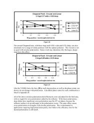
<strong>Chaparral</strong> Feed - Circular <strong>and</strong> Linear3 rings 0.17 wide x 0.30 deep800.5Dish Efficiency(%)7570650 0.1 0.2 0.3 0.40.4f/D0.30.2<strong>Septum</strong> EffLinear Eff<strong>Septum</strong> f/DLinear f/DRing position - wavelengths behind rimFigure 40The second <strong>Chaparral</strong> horn, <strong>with</strong> three rings each 0.20λ wide <strong>and</strong> 0.33λ deep, was alsosimulated over a range of choke positions <strong>with</strong> the septum polarizer. This version is notas good <strong>with</strong> circular polarization. Future work may determine why the larger, deeperrings have this effect.<strong>Chaparral</strong> Feed - Circular <strong>and</strong> Linear3 rings 0.20 wide x 0.33 deep800.5Dish Efficiency(%)7570650 0.1 0.2 0.3 0.40.4f/D0.30.2<strong>Septum</strong> EffLinear Eff<strong>Septum</strong> f/DLinear f/DRing position - wavelengths behind rimFigure 41Like the <strong>VE4MA</strong> horn, the best f/D at each ring position, as well as the phase center, notshown, do not change <strong>with</strong> polarization. Calculated phase center for each combination islisted in Appendix B.All of the above circular polarization dish efficiencies were calculated for the feed only,<strong>with</strong> no regard for cross-polarization added by the reflector. With linear polarization,deep dishes have significant cross-polarization near the 45º cut planes, because thereflector surface is at an odd angle to the polarization vector. The same effect causescross-polarization at all angles <strong>with</strong> circular polarization. This is detrimental inapplications requiring high polarization purity, but I believe the efficiency loss for thedesired polarization is still small.
Small DishesAll our comparisons were for a dish 20λ in diameter. Many hams must make do <strong>with</strong>much smaller dishes, 10λ or smaller diameter. We have seen that the best <strong>feeds</strong> are 1.9λin diameter, so the blockage is significant on a small dish. Some of the small <strong>VE4MA</strong>variations also provide good performance, <strong>and</strong> would have less blockage. The tradeoff iswhether the larger blockage makes the efficiency of the larger feed lower than the smallerfeed.In Figure 42, efficiencies curves for several of the better <strong>feeds</strong> are plotted for a 10λdiameter dish, using the blockage diameter of each feed. It is clear that the largersuper-<strong>VE4MA</strong> feed is still superior for all but very deep dishes. Even though thecalculated efficiency is significantly lower than for larger dishes, it is still higher than theefficiency of other <strong>feeds</strong>.Construction noteGetting the rings in the right position is important for best performance, so making thering adjustable would be a real advantage. WD5AGO has found that at least six points ofgood contact around the perimeter are needed for optimum performance.Sun noise measurement <strong>and</strong> circular polarizationWe can evaluate the performance of a dish antenna by sun noise measurements,comparing the noise power received from the sun <strong>with</strong> the noise power received fromcold sky. However, this does not evaluate the quality of circular polarization – noise isr<strong>and</strong>omly polarized in both instances, so we may expect the same results as we measurefor linear polarization. There are no celestial sources <strong>with</strong> well-defined polarization, sofar-field polarization measurements for good-sized antennas are difficult unless a largeanechoic chamber is available. A ground-reflection range of the type typically used foramateur antenna measurements is unsuitable for circular polarization; according toHanson 11 , “on a ground reflection antenna test range, the antenna under test must berotated, or tedious calibration procedures must be employed to account for the differencein the reflection coefficients of the range surface for the horizontal <strong>and</strong> verticalcomponents of the field.”Without measurements, we must rely on simulation to evaluate circularly-polarized <strong>feeds</strong>.We can also simulate pure circular polarization, using two orthogonal modes <strong>with</strong> equalamplitudes <strong>and</strong> 90° phase difference. Simulations <strong>with</strong> pure circular polarization showthe same calculated dish efficiencies as pure linear polarization. Therefore, we wouldexpect to measure the same sun noise <strong>with</strong> either linearly- or circularly-polarized feed,<strong>and</strong> WD5AGO has confirmed this experimentally.With a real polarizer, measurement or simulation results may differ from those <strong>with</strong> purepolarization, because of polarizer losses or imperfect polarization generated by thepolarizer. Certain combinations of feedhorn <strong>and</strong> imperfect polarization might result inslightly better performance than pure polarization. In the absence of good measurements,we must rely on simulation results for <strong>polarizers</strong> <strong>and</strong> circular polarization.
Feed choices for 10λ diameter DishOriginal <strong>VE4MA</strong> 0.50λ wide x 0.50λ deep, back 0.15λSuper <strong>VE4MA</strong> 0.60λ wide x 0.45λ deep, back 0.15λsmall <strong>VE4MA</strong> 0.40λ wide x 0.25λ deep, back 0.35λsmall <strong>VE4MA</strong> 0.25λ wide x 0.25λ deep, back 0.35λ<strong>Chaparral</strong> 3 rings 0.17λ wide x 0.33λ deep, back 0.25λFigure 42Dish diameter = 10 λ Feed diameter = BlockageMAX Possible Efficiency <strong>with</strong> Phase errorREAL WORLD at least 15% lower90Parabolic Dish Efficiency %80706050403020101 dB2 dB3 dB4 dB5 dB6 dB7 dB8 dB0.250.3 0.4 0.5 0.6 0.7 0.8 0.9Parabolic Dish f/D<strong>W1GHZ</strong> 2006
SummaryThe test results in Appendix A are very encouraging. The measurements by WD5AGOare completely independent from the simulations by <strong>W1GHZ</strong>, yet the comparable resultsare consistent. The efficiency derived from sun noise measurements is 12 to 14% lowerthan efficiency calculated from simulations in all cases. Previous tests have shown realworld efficiency to be about 15% lower than simulation for small dishes. Therefore, wemay believe that the measurements validate the simulation results.Our results have surpassed the original objective. In addition finding excellentcombinations of the <strong>VE4MA</strong> <strong>and</strong> <strong>Chaparral</strong> feedhorns <strong>with</strong> septum <strong>polarizers</strong>, we havediscovered some improved dimensions for these feedhorns which offer improvedperformance. Measured efficiencies as high as 65% surpass any previous amateur resultsfor a prime-focus dish, as well as most commercial results. Thus, we may draw someconclusions:• The original <strong>VE4MA</strong> feedhorn provides good efficiency for a wide range of dish f/D.• The <strong>Chaparral</strong> feedhorn provides somewhat better efficiency for a wide range of dishf/D, <strong>and</strong> the highest to date for very deep dishes, <strong>with</strong> f/D ~ 0.25.• A larger version of the <strong>VE4MA</strong> feed, which we call the “Super <strong>VE4MA</strong>,” providesexcellent efficiency, the highest to date for a prime-focus dish, but over a smallerrange of dish f/D.• Smaller versions of the <strong>VE4MA</strong> feed work as well as the original over a broad rangeof ring dimensions, offering lower blockage for very small dishes.• The probe is not part of the antenna. It could be 100 meters away, at the far end of thefeedline. The loss might reduce the transmitted power, but will not affect the radiationpattern of the antenna.• The polarizer is not part of the antenna – just like the probe.• The septum polarizer, or any other polarizer, does not affect the antenna radiation,except to make the polarization circular; any polarizer that excites the antenna <strong>with</strong>good CP will result in the same pattern. Of course, a poor polarizer will degradeperformance.• All these feedhorns work well (in simulation) <strong>with</strong> the OK1DFC septum polarizer toprovide circular polarization, but the <strong>VE4MA</strong> feed <strong>and</strong> variations degrade slightly forf/D < 0.35.• For linear polarization, horn diameters of 0.71λ <strong>and</strong> 0.77λ work equally well, <strong>and</strong>there is no reason to believe that intermediate diameters will not work as well. TheOK1DFC septum polarizer works best <strong>with</strong> a waveguide diameter of 0.71λ.• The range of feed dimensions that yields very good performance providesopportunities to use available materials effectively.If you have a feed that is working well <strong>and</strong> providing good results, there is no need tochange it. However, if you feel that a better feed could help, or if you don’t have a feedyet <strong>and</strong> are still deciding, then one of the improved <strong>feeds</strong> described here could be a goodchoice. But the most important part is to put a feed in your dish <strong>and</strong> get it on the air!
References1. B.W. Malowanchuk, <strong>VE4MA</strong>, "<strong>VE4MA</strong> 3456 MHz circular polarization feed horn,"North Texas Microwave Society Feedpoint, Nov/Dec 1991.2. Zdenek Samek, OK1DFC, “Feed for Parabolic Dish <strong>with</strong> Circular Polarization,”CD-ROM for 10 th International EME Conference 2002 in Prague. www.ok1dfc.com3. www.ansoft.com4. P. Wade, <strong>W1GHZ</strong>, “Underst<strong>and</strong>ing Circular Waveguide – Experimentally,” QEX,Jan/Feb 2001, pp. 37-48. www.w1ghz.org/QEX/circular_wg.pdf5. P. Wade, <strong>W1GHZ</strong>, The <strong>W1GHZ</strong> Microwave Antenna Book – Online, www.w1ghz.org6. A. Kumar, "Reduce Cross-Polarization in Reflector-Type Antennas," Microwaves,March 1978, pp. 48-51.7. R. Wohlleben, H. Mattes, O. Lochner, "Simple small primary feed for large openingangles <strong>and</strong> high aperture efficiency," Electronics Letters, 21 Sept. 1972, pp. 181-183.(reprinted in A.W. Love, Electromagnetic Horn Antennas, IEEE, 1976, pp. 181-183.)8. M. Chen & G. Ts<strong>and</strong>oulas, “A wide-b<strong>and</strong> square-waveguide array polarizer,” IEEETransactions on Antennas <strong>and</strong> Propagation, May 1973, pp. 389-391.9. P. Wade, <strong>W1GHZ</strong>, “Analysis of the OK1DFC <strong>Septum</strong> Feed,” DUBUS, 1/2003, pp.22-38.10. J. Bornemann & V.A. Labay, “Ridge Waveguide Polarizer <strong>with</strong> Finite <strong>and</strong> Stepped-Thickness <strong>Septum</strong>,” IEEE Transactions on Microwave Theory <strong>and</strong> Techniques,August 1995, pp. 1782-1787.11. J.S. Hollis, T.J. Lyon, & L. Clayton, Jr., “Microwave Antenna Measurements,”Scientific-Atlanta, July, 1970, p. 10-13.
Appendix ACircularly-polarized Feedhorn Measured DataTommy Henderson WD5AGOHere we have a comparison of several circularly-polarized <strong>feeds</strong> for 13cm. All scalarrings are adjusted for best G/T for a 2.4 M, 0.37 f/D Dish (20λ diameter at 13cm). Feedblockage was not as big a factor in G/T as seen from the chart. To avoid blockage, whichlowers the gain in smaller dishes, a closer spaced 3-ring scalar, <strong>with</strong> rings spaced 0.15λwas produced. As seen from <strong>W1GHZ</strong> data, a 0.2λ spacing would have yielded another 1% efficiency placing it about 62%, still 2% to 3% down from the Super <strong>VE4MA</strong> <strong>with</strong> onelarge ring. All three-ring versions yielded EME echoes 2 to 3 dB out of the noise <strong>with</strong> a35° K front end.Measured Efficiency, 20-wavelength Dish, f/D =0.37WD5AGO 2006Dish Efficiency (dB)66%64%62%60%58%56%54%52%50%48%46%44%42%40%Measured Dish Efficiency at 2.3 GHzRound septum, no rings 51%1 Ring 0.3 wide x 0.3 deep 56%2 Rings 0.17 wide x 0.33 deep 58%3 rings 0.15 wide x 0.33 deep 60%Super <strong>VE4MA</strong>, 1 Ring 0.6 wide x65%0.45 deep3 Rings 0.17 wide x 0.33 deep,61%7-screw polarizer<strong>VE4MA</strong> 0.5 wide x 0.5 deep,58%5-screw polarizerMeasured dish efficiency from sun noise measurement below
Measured Sun Noise, 20-wavelength Dish, f/D =0.37WD5AGO 20061110.5Sun Noise (dB)109.59FeedMeasured Sun Noise at 2.3 GHz (SFU@75)Same data in tabular form. The measured dish efficiency is 12 to 14% lower thansimulated. Typical difference for real world is 15% below simulation for a small dish.Feed Horn Ring Ring Polarizer SunColdSky Measured Simulateddiameter width Depth NoisetoGround Efficiency Efficiencyλ λ λ dB dBRound 0.71 <strong>Septum</strong> 9.9 5.2 51% 64%<strong>VE4MA</strong> 0.71 0.3 0.3 <strong>Septum</strong> 10.3 6.6 56% 70%2 x<strong>Chaparral</strong> 0.71 0.17 0.33 <strong>Septum</strong> 10.4 7 58%3 x<strong>Chaparral</strong> 0.71 0.15 0.33 <strong>Septum</strong> 10.5 7 60% 72%<strong>VE4MA</strong> 0.71 0.6 0.45 <strong>Septum</strong> 10.9 6 65% 78%3 x0.17 0.33 7-screw 10.6 6.8 61%<strong>Chaparral</strong> 0.76<strong>VE4MA</strong> 0.77 0.5 0.5 5-screw 10.4 6.8 58%<strong>VE4MA</strong> 0.71 0.3 0.3 hybrid 9.6 4.5Noisehorn 7.8
Appendix BSimulation Data from HFSS<strong>VE4MA</strong> Feedhorns 0.77λ Horn Diameter<strong>with</strong> different ring sizes <strong>and</strong> positions<strong>W1GHZ</strong> 2006Horn Ring Ring behind Dish f/D Phase Return FrontDiameter width depth rim efficiency best center Loss to Backλ λ λ λ λ dB dBOriginal <strong>VE4MA</strong>0.77 0.5 0.5 -0.05 69% 0.49 -0.18 22.5 230 69.5% 0.43 -0.24 24 190.05 70% 0.41 -0.23 24 170.1 71% 0.36 -0.17 21.5 140.15 71% 0.32 0.014 18.5 130.2 68% 0.32 0.11 17.5 12Small ring0.77 0.35 0.35 -0.05 71% 0.49 0.1 18 270 72% 0.5 0 19 260.05 71% 0.49 -0.06 20.5 150.15 70% 0.42 -0.11 24.5 110.25 71% 0.36 -0.1 24.5 160.3 71% 0.33 0 21.5 140.35 69% 0.32 0.08 20 13Super <strong>VE4MA</strong>0.77 0.6 0.45 0 72.8% 0.43 -0.37 17 230.05 75.6% 0.43 -0.37 18 240.15 79.3% 0.38 -0.07 19.5 230.25 74.1% 0.36 0.2 19 210.35 68.2% 0.37 0.14 20.5 231296 published dimensions0.77 0.52 0.52 0.1 71.1% 0.34 -0.11 20.5 130.15 70% 0.33 0.1 18 132304 published dimensions0.77 0.54 0.48 0 68% 0.43 -0.2 180.77 0.55 0.55 0.15 67% 0.33 0.11 18.5 12
<strong>VE4MA</strong> Feedhorns 0.71λ Horn Diameter<strong>with</strong> different ring sizes <strong>and</strong> positions<strong>W1GHZ</strong> 2006Horn Ring Ring behind Dish f/D Phase Return FrontDiameter width depth rim efficiency best center Loss to Backλ λ λ λ λ dB dBOriginal <strong>VE4MA</strong> ring size0.71 0.5 0.5 -0.025 68.5% 0.43 -0.21 19 110 68% 0.42 -0.21 180.025 68.5% 0.41 -0.24 21.5 170.05 68% 0.36 -0.24 22 160.075 69% 0.35 -0.21 22 150.1 69% 0.33 -0.18 21.5 140.125 70% 0.31 -0.11 20 130.15 70.5% 0.3 -0.03 18.5 120.175 69.5% 0.29 0.1 17 120.2 67% 0.3 0.18 16 110.225 66% 0.31 0.21 16 120.25 66% 0.32 0.2 15.5 14Super <strong>VE4MA</strong>0.71 0.6 0.45 0 72.2% 0.43 -0.4 15.5 220.05 74.6% 0.42 -0.37 16.5 230.1 76.7% 0.38 -0.3 17 220.15 78.8% 0.37 -0.14 17 210.2 77.3% 0.35 0.13 17 210.25 74.5% 0.35 0.23 17 190.35 68.9% 0.36 0.17 17 21Small ring0.71 0.35 0.35 0 71% 0.49 0 16 250.05 70.5% 0.49 -0.07 17 140.1 70% 0.44 -0.1 18.5 130.15 70% 0.42 -0.13 20 110.2 70.5% 0.36 -0.13 21.5 180.25 71% 0.33 -0.11 22.5 160.3 71% 0.31 -0.03 21 140.35 69% 0.31 0.086 18.5 12Small ring0.71 0.4 0.25 0 69% 0.48 0.07 14 230.05 70.3% 0.49 0 15 250.15 71.5% 0.44 -0.08 17 250.25 72% 0.37 -0.11 19.5 220.35 73% 0.32 -0.07 23 160.4 73% 0.31 0 21.5 150.45 70.8% 0.3 0.1 13
<strong>VE4MA</strong> Feedhorns 0.71λ Horn Diameter (cont.)<strong>with</strong> different ring sizes <strong>and</strong> positions<strong>W1GHZ</strong> 2006Horn Ring Ring behind Dish f/D Phase Return FrontDiameter width depth rim efficiency best center Loss to Backλ λ λ λ λ dB dBSmall ring0.71 0.4 0.3 0 70.6% 0.48 0.02 15 260.05 71.0% 0.49 -0.04 16 260.15 71.5% 0.42 -0.11 18.5 240.25 72.0% 0.35 -0.11 22 190.35 73.0% 0.31 0 21 140.4 71.8% 0.29 0 19 13Small ring92 0.25 0.25 0.05 70.3% 0.49 0.06 15 260.15 70.5% 0.41 -0.04 17.5 240.25 70.0% 0.36 -0.06 20 210.35 70.3% 0.32 -0.06 21.5 170.4 70.0% 0.31 0 21 15Smallest ring simulated0.71 0.12 0.26 0 70.0% 0.41 0.1 14 240.05 70.3% 0.41 0.06 15.5 220.15 70.0% 0.36 0 16.5 200.25 69.6% 0.36 0 19.5 180.3 68.0% 0.32 0 20 170.35 68.0% 0.32 0 20 16Single Ring of <strong>Chaparral</strong>0.71 0.2 0.33 0.05 69% 0.42 0 17 210.15 67% 0.36 -0.03 18.5 180.25 67% 0.32 -0.03 21 160.35 66% 0.31 0.014 21 13
<strong>VE4MA</strong> feed, 0.71λ horn diameter <strong>with</strong> different ring dimensions, all 0.15λ behind rim<strong>W1GHZ</strong> 2006Dish efficiencyWIDE > 0.75λ 0.7λ 0.65λ 0.6λ 0.55λ 0.5λ 0.45λ 0.4λ 0.35λ 0.3λ 0.25λDEEP λ0.65 73.0% 73.8% 68.5%0.6 72.0% 73.0% 68.0%0.55 72.8% 70.8% 67.0%0.5 70.6% 72.8% 75.9% 70.2% 70.5% 70.3% 69.0%0.45 74.3% 75.5% 77.6% 78.8% 60.0% 70.3% 70.0% 69.5%0.4 77.5% 78.1% 78.7% 79.4% 62.0% 70.4% 70.6% 70.0% 69.0%0.35 77.8% 78.5% 78.5% 72.0% 64.0% 70.5% 71.0% 70.4% 70.0% 69.0% 68.0%0.3 77.8% 78.0% 76.8% 47.0% 67.0% 70.0% 71.5% 71.5% 71.0% 70.0% 69.0%0.25 75.2% 73.0% 62.6% 50.0% 66.5% 70.5% 71.4% 71.5% 71.3% 71.0% 70.5%0.2 70.0% 71.0% 70.7%0.15 68.0% 68.0% 68.0%0.1 63.5%Best f/DWIDE > 0.75λ 0.7λ 0.65λ 0.6λ 0.55λ 0.5λ 0.45λ 0.4λ 0.35λ 0.3λ 0.25λDEEP λ0.65 0.41 0.42 0.420.6 0.37 0.42 0.370.55 0.35 0.42 0.310.5 0.38 0.36 0.36 0.31 0.3 0.31 0.310.45 0.38 0.37 0.37 0.37 0.25 0.33 0.33 0.360.4 0.41 0.41 0.39 0.39 0.31 0.36 0.36 0.36 0.360.35 0.42 0.42 0.42 0.41 0.41 0.42 0.41 0.41 0.42 0.42 0.410.3 0.43 0.43 0.43 0.49 0.42 0.42 0.43 0.42 0.42 0.42 0.420.25 0.45 0.45 0.49 0.25 to 0.5 0.33 0.43 0.43 0.44 0.43 0.43 0.410.2 0.44 0.49 0.430.15 0.44 0.45 0.440.1 0.41
<strong>VE4MA</strong> feed, 0.71λ horn diameter <strong>with</strong> different ring dimensions, all 0.15λ behind rim<strong>W1GHZ</strong> 2006Phase Center, wavelengths in front of apertureWIDE > 0.75λ 0.7λ 0.65λ 0.6λ 0.55λ 0.5λ 0.45λ 0.4λ 0.35λ 0.3λ 0.25λDEEP λ0.65 0.17 0 0.080.6 0.24 0.08 00.55 0.26 0.14 0.1860.5 0.3 0.26 0.13 -0.03 -0.03 0 -0.040.45 0.17 0.13 -0.01 -0.14 -0.2 -0.19 -0.14 -0.170.4 -0.03 -0.08 -0.17 -0.27 -0.23 -0.2 -0.19 -0.17 -0.140.35 -0.11 -0.18 -0.26 -0.23 -0.14 -0.18 -0.16 -0.13 -0.13 -0.1 -0.070.3 -0.16 -0.24 -0.33 -0.53 -0.1 -0.13 -0.11 -0.11 -0.1 -0.086 -0.040.25 -0.27 -0.39 -0.06 -0.05 -0.08 -0.08 -0.08 -0.06 -0.04 -0.040.2 0 0 00.15 0.07 0.086 0.070.1 0.14
<strong>Chaparral</strong>-style Feedhorns 0.71λ Horn Diameter<strong>with</strong> different ring sizes <strong>and</strong> positions<strong>W1GHZ</strong> 2006Horn Ring Ring behind Dish f/D Phase Return FrontDiameter width depth rim efficiency best center Loss to Backλ λ λ λ λ dB dBOne ring (<strong>VE4MA</strong>), 1.11λ Blockage0.71 0.2 0.33 0.05 69% 0.42 0 17 210.15 67% 0.36 -0.03 18.5 180.25 67% 0.32 -0.03 21 160.35 66% 0.31 0.014 21 13Two rings, 1.51λ Blockage0.71 0.2 0.33 0.05 71.3% 0.49 -0.06 17 260.15 72% 0.41 -0.13 19 230.25 72% 0.36 -0.11 22 170.35 72% 0.31 0.11 20 14Three rings, 1.91λ Blockage0.71 0.2 0.33 0.05 72.2% 0.48 -0.11 19 290.15 74.3% 0.42 -0.18 19.5 230.25 76.2% 0.36 -0.11 22 180.35 74.2% 0.31 0.13 19 16Four rings, 2.31λ Blockage0.71 0.2 0.33 0.05 72.6% 0.49 -0.16 330.15 75.4% 0.43 -0.21 19.5 260.25 76.8% 0.37 -0.08 22 210.35 72.0% 0.31 0.1 22 18Three rings, 1.73λ Blockage0.71 0.17 0.3 0 72% 0.49 0 15.5 300.05 73% 0.48 -0.04 16.5 310.15 74% 0.42 -0.14 21 260.25 75% 0.37 -0.14 18 190.35 74.5% 0.32 0.1 21.5 170.4 73% 0.3 0.13 18.5 15Four rings, 2.07λ Blockage0.71 0.17 0.3 0.25 75.3% 0.37 -0.16 21.5 21Three rings, 2.33λ Blockage0.71 0.27 0.3 0.25 76.7% 0.37 -0.09 21.5 21
<strong>Chaparral</strong>-style Feedhorns 0.71λ Horn Diameter (cont.)<strong>with</strong> different ring sizes <strong>and</strong> positions<strong>and</strong> constant blockage<strong>W1GHZ</strong> 2006Horn Ring Ring behind Dish f/D Phase Return FrontDiameter width depth rim efficiency best center Loss to Backλ λ λ λ λ dB dBOne ring (Super <strong>VE4MA</strong>), 1.91λ Blockage0.71 0.6 0.45 0 72.2% 0.43 -0.4 15.5 220.05 74.6% 0.42 -0.37 16.5 230.1 76.7% 0.38 -0.3 17 220.15 78.8% 0.37 -0.14 17 210.2 77.3% 0.353 0.13 17 210.25 74.5% 0.35 0.23 17 190.35 68.9% 0.36 0.17 17 21Two rings, 1.91λ Blockage0.71 0.3 0.33 0.05 73.0% 0.49 -0.13 17 300.15 74.5% 0.42 -0.18 19.5 230.25 76.5% 0.36 -0.1 22 180.35 73.0% 0.31 0.13 18 16Three rings, 1.91λ Blockage0.71 0.2 0.33 0.05 72.2% 0.48 -0.11 19 290.15 74.3% 0.42 -0.18 19.5 230.25 76.2% 0.36 -0.11 22 180.35 74.2% 0.31 0.13 19 16Four rings, 1.91λ Blockage0.71 0.15 0.33 0.05 71.9% 0.48 -0.11 19 280.15 73.2% 0.42 -0.2 19.5 240.25 74.2% 0.35 -0.13 22 190.35 74.3% 0.28 0.1 30 170.4 71.0% 0.27 0.13 17.5 17
<strong>VE4MA</strong> Feedhorns <strong>with</strong> <strong>Septum</strong> Polarizer0.71λ Horn Diameter, RHCP<strong>with</strong> different ring sizes <strong>and</strong> positions<strong>W1GHZ</strong> 2006Ring Ring behind Dish f/D Phase Return Isolation 1dB Axialwidth depth rim efficiency best center Loss Ratioλ λ λ λ dB dB degreesOriginal <strong>VE4MA</strong> ring dimensions0.5 0.5 0 67 0.42 -0.21 32 20 200.1 68 0.35 -0.21 32 23 120.15 69.5 0.32 -0.06 31 20 120.2 66 0.31 0.17 31 17 150.3 63 0.35 0.18 32 16 18Super <strong>VE4MA</strong>0.6 0.45 0.05 74 0.41 -0.37 31.5 17 130.15 79 0.37 -0.186 32 17 90.25 75.8 0.36 0.23 30 17 170.35 70.1 0.36 0.18 31 18 36Smaller ring variations0.35 0.35 0 71 0.49 0 31 16.5 700.1 70.5 0.43 -0.1 34 18.5 240.15 70.5 0.42 -0.13 30 20 190.2 70.5 0.37 -0.13 31 22 180.3 68 0.32 -0.01 31 23 130.35 66 0.31 0.07 32 23 150.35 0.25 0.05 70.5 0.49 0.04 31 15 320.15 72 0.43 -0.06 31 17 300.25 71 0.41 -0.1 30.5 20 180.35 70.5 0.35 -0.086 31.5 23 130.4 70 0.32 0 32 23 130.4 0.25 0.05 70 0.49 0.03 30.5 15 270.15 72 0.43 -0.07 30 17.5 280.25 72 0.41 -0.13 32 20.5 170.35 71.5 0.36 -0.085 32 24 130.4 71 0.31 0 29.5 23 12.50.45 68 0.31 0.1 31 19.5 150.5 0.25 0.15 70.5 0.43 -0.07 31.5 17.5 180.25 0.2 0.15 71.5 0.43 0 31 16 330.12 0.26 0.3 68 0.36 0 31.5 21 200.35 0.25 0.15 72 0.43 -0.06 31 17 30
<strong>VE4MA</strong> Feedhorns <strong>with</strong> <strong>Septum</strong> Polarizer0.71λ Horn Diameter, RHCPPerformance over Frequency<strong>W1GHZ</strong> 2006Freq Ring Ring behind Dish f/D Phase Return Isolationwidth depth rim efficiency best center LossGHz λ λ λ λ dB dB2.0 0.35 0.35 0.2 68% 0.41 -0.07 18.5 92.1 69% 0.38 -0.086 23 122.2 69% 0.37 -0.11 25 19.52.3 70.5% 0.37 -0.13 31 222.4 70% 0.37 -0.11 26 19.52.5 70.5% 0.37 -0.11 21 172.6 70% 0.36 -0.1 18.5 19
<strong>Chaparral</strong>-style Feedhorn <strong>with</strong> <strong>Septum</strong> Polarizer0.71λ Horn Diameter, RHCP<strong>with</strong> different ring sizes <strong>and</strong> positions<strong>W1GHZ</strong> 2006Ring Ring behind Dish f/D Phase Return Isolation 1dB Axialwidth depth rim efficiency best center Loss Ratioλ λ λ λ dB dB degreesThree rings, 1.73λ Blockage0.17 0.3 0.05 72.5% 0.49 -0.04 31 17 390.15 73% 0.43 -0.14 31.5 19 190.25 74% 0.37 -0.13 32.5 22 140.35 75% 0.32 0.02 31.5 21 120.4 70% 0.31 0.11 32 19Three rings, 1.91λ Blockage0.2 0.33 0.05 72.0% 0.49 -0.11 33 18 270.15 73% 0.42 -0.2 32 20 180.25 73% 0.35 -0.14 32.5 23.5 120.35 71.5% 0.31 0.1 32 19.5 9