ispDOWNLOAD Cables Data Sheet - Laurent Deschamps
ispDOWNLOAD Cables Data Sheet - Laurent Deschamps
ispDOWNLOAD Cables Data Sheet - Laurent Deschamps

Create successful ePaper yourself
Turn your PDF publications into a flip-book with our unique Google optimized e-Paper software.
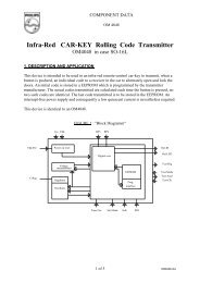
®<strong>ispDOWNLOAD</strong> <strong>Cables</strong>TMFor Programming Lattice ISP DevicesMarch 2005Features■■■■Support for All Lattice ProgrammableProducts (Including ispPAC ® and ORCA ®Families)• 1.8V to 5V programming• Ideal for design prototyping and debuggingConnect to Multiple PC Interfaces• USB (v.1.0, v.2.0 ready)• PC Parallel PortEasy-to-Use Programming Connectors• Versatile flywire, 2 x 5 (.100”) or 1 x 8 (.100”)connectors6 Feet (2 Meters) or More of ProgrammingCable Length (PC to DUT)<strong>ispDOWNLOAD</strong> <strong>Cables</strong>Lattice <strong>ispDOWNLOAD</strong> cables are designed to facilitatein-system programming for all Lattice SemiconductorISP devices directly from a PC. With in-system programmability,hardware functions can be programmedand modified in real-time on the system board to giveadditional product features, shorten system design anddebug cycle time, enhance product manufacturabilityand simplify field upgrades.After you complete your logic design and create a programmingfile with the ispLEVER ® development tools,you can use ispVM ® System software to programdevices on your board. The ispVM System softwareautomatically generates the appropriate ISP commands,programming addresses and programming databased on information stored in the programming file andparameters you set in ispVM. Programming signals arethen generated from the USB or parallel port of a PCand directed through the <strong>ispDOWNLOAD</strong> Cable to thedevice, no additional components are required for programming.ispVM System software is included with all Latticedesign tool products and available for download fromthe Lattice web site at www.latticesemi.com.<strong>ispDOWNLOAD</strong> Cable Pin DefinitionsThe functions provided by of the <strong>ispDOWNLOAD</strong> cablescorrespond with available functions on Lattice programmabledevices. Since some devices contain differentprogramming features, the specific functions providedby the <strong>ispDOWNLOAD</strong> cable may depend on theselected target device. ispVM System software willautomatically generate the appropriate functions basedon the selected device. See Table 1 for an overview ofthe <strong>ispDOWNLOAD</strong> cable functions.Table 1. <strong>ispDOWNLOAD</strong> Cable Pin Definitions<strong>ispDOWNLOAD</strong>Cable PinName<strong>ispDOWNLOAD</strong> CableInput/OutputDescriptionVCC Programming Voltage InputConnect to V CC or V CCJ plane of the target device. TypicalI CC = 10mA. (Note: this may not be the same as a targetdevice’s V CCO plane).SDO/TDO Test <strong>Data</strong> Output InputUsed to shift data out via the IEEE1149.1 (JTAG)programming standard.SDI/TDI Test <strong>Data</strong> Input OutputUsed to shift data in via the IEEE1149.1 programmingstandard.ispEN/Enable/PROGEnable Output Enable device to be programmedTRST Test Reset Output Optional IEEE 1149.1 state machine reset.DONE DONE Input Done indicates status of configurationMODE/TMS Test Mode Select Input Output Used to control the IEEE1149.1 state machine.GND Ground Input Connect to ground plane of the target deviceSCLK/TCK Test Clock Input Output Used to clock the IEEE1149.1 state machineINIT Initialize Input Indicates that ORCA device is ready for configuration.www.latticesemi.com 1 dlcable_20
Lattice Semiconductor<strong>ispDOWNLOAD</strong> <strong>Cables</strong>Figure 1. <strong>ispDOWNLOAD</strong> Cable In-System Programming Interface for the PC (HW-USB-1A) 1FunctionColorToPC6'HW-USB-1AV CCSDO/TDOSDI/TDIispEN/Enable/PROGTRST/DONEMODE/TMSGNDSCLK/TCKINITRedBrow nOrangeYellowGreenPurpleBlackWhiteBlueToSystemBoard1. Lattice PAC-Designer ® software does not support programming with the HW-USB-1A cable. To program ispPAC devices with the HW-USB-1A, use the ispVM System software.Figure 2. <strong>ispDOWNLOAD</strong> Cable In-System Programming Interface for the PC (HW7265-DL3 or HW7265-DL3A) 1ToPCGrey Housing25-pinParallelPortAdapterRJ-45 ConnectorEight Positions6'FunctionV CCSDO/TDOSDI/TDIispEN/Enable/ProgTRSTMODE/TMSGNDSCLK/TCKColorRedBrownOrangeYellowGreenPurpleBlackWhiteToSystemBoard1. HW7265-DL3 and HW7265-DL3A are functionally equivalent products.Figure 3. <strong>ispDOWNLOAD</strong> Cable In-System Programming Interface for the PC (pDS4102-DL2 or pDS4102-DL2A)ToPCpDS4102-DL2 – Blue HousingpDS4102-DL2A – Grey Housing25-pinParallelPortAdapterRJ-45 ConnectorEight Positions6'.100" Center-SpacingEight Positions.01µf*CapacitorEnd ViewNote: Capacitor Recommended on System BoardFunction Pin #V CC1SDO/TDO2SDI/TDI3ispEN/Enable/PROG 4TRST5MODE/TMS6GND7SCLK/TCK8ToSystemBoardFigure 4. <strong>ispDOWNLOAD</strong> Cable In-System Programming Interface for the PC (HW7265-DL2 or HW7265-DL2A)HW7265-DL2 – Blue HousingHW7265-DL2A – Grey HousingEnd ViewOverhead View of PC BoardConnectorPinoutToPC25-pinParallelPortAdapterRJ-45 ConnectorEight Positions6'Pin # Function2 GND4 GND6 VCC8 GND10 ispEN/Enable/PROGFunction Pin #SCLK/TCK 1MODE/TMS 3SDI/TDI 5SDO/TDO 7TRST 9Pin #13ToSystem 5Board 79FunctionSCKL/TCKMODE/TMSSDI/TDISDO/TDOTRSTFunctionGNDGNDVCCGNDispEN/Enable/PROGPin #246810Programming SoftwareispVM System is the preferred programming management software tool for all Lattice devices and downloadcables. The latest version of ispVM System is always available for download from the Lattice web site atwww.latticesemi.com/software.PAC-Designer is the design tool for Lattice ispPAC and ispCLOCK devices. PAC-Designer can also be used to programthese devices. If using PAC-Designer for programming, pay special attention to the notes in this document,and the PAC-Designer system help.2
Lattice Semiconductor<strong>ispDOWNLOAD</strong> <strong>Cables</strong>Refer to the following table when connecting a fly-wire download cable to systems that use the 1x8-position or 2x5-position connectors. For newer Lattice FPGA families (such as the LatticeEC or LatticeECP-DSP families), a1x10 connector used in conjunction with the <strong>ispDOWNLOAD</strong> USB cable adds support for the DONE and INITN signals.Both of these signals are inputs to the cable, and can be used to help verify device configuration.Table 2. Fly-wire Conversion ReferenceFunction Fly-wire Cable 1x10 Connector 1x8 Connector 2x5 Connector1V CC Red 1 1 6TDO/SDO Brown 2 2 7TDI/SDI Orange 3 3 5ispEN 2 /Enable/PROGRAMN Yellow 4 4 10TRST 3 Green 5 5 9TMS/MODE Purple 6 6 3GND Black 7 7 4 (2 and 8)TCK 4 /SCLK White 8 8 1DONE 3 Green 9INITN Blue 101. For devices that have a V CCJ pin, the V CCJ must be connected to the cable's V CC, and a 0.1µF decoupling capacitor is required on V CCJclose to the device. Please refer to the device data sheet to determine if the device has a V CCJ pin.2. For older Lattice ISP devices, a 0.01µF decoupling capacitor is required on ispEN/ENABLE of the target board.3. The TRST and DONE pin is multiplexed on the <strong>ispDOWNLOAD</strong> USB cable. If the device TRST signal is available on the board, connect theUSB fly-wire TRST/DONE wire to TRST. If the device DONE signal is available on the board (or if both TRST and DONE are available),connect the USB fly-wire TRST/DONE wire to DONE. Please make sure the correct setting is selected in ispVM (Options, Cable and I/OPort Setup). This will tell ispVM whether the TRST/DONE cable is used as a TRST or a DONE signal.4. For newer FPGA devices (i.e. LatticeEC/ECP), a 4.7K pull-down resister is recommended on TCK of the target board.Table 3 lists the recommend pin connections. Please contact Lattice technical support for information on unlisteddevice families. (e-mail: techsupport@latticesemi.com, phone: 1-800-LATTICE).Table 3. Recommend Cable ConnectionsDevice FamilyTCK, TMS,TDI and TDOispEN/ENABLE 1PROGRAMN/PRGM TRST 2 DONE 3 INITN 3LatticeXP Mandatory N/A Do Not Connect N/A Optional OptionalLatticeEC/ECP Mandatory N/A Do Not Connect N/A Optional OptionalORCA/FPSC Mandatory N/A Mandatory N/A Optional OptionalispXPGA ® Mandatory N/A Optional N/A Optional OptionalispXPLD Mandatory N/A Optional N/A Optional OptionalispMACH 4000 Mandatory N/A N/A N/A N/A N/AispMACH/ispLSI ® 5000 Mandatory N/A N/A N/A N/A N/AMACH ® 4A 4 Mandatory Optional N/A Optional N/A N/AispGDX2 Mandatory N/A N/A N/A N/A N/AispClock Mandatory N/A N/A N/A 5 N/A N/AispPAC-POWR Mandatory N/A N/A Optional 5 N/A N/AispPAC Mandatory N/A N/A N/A 5 N/A N/A1. Please refer to the <strong>ispDOWNLOAD</strong> Cable ispEN Pin section below for detailed information on connecting the ispEN/ENABLE pin.2. Please refer to the <strong>ispDOWNLOAD</strong> Cable TRST Pin section below for detailed information on connecting the TRST pin.3. The DONE and INITN signals are only available on the <strong>ispDOWNLOAD</strong> USB cable. These signals are inputs to the cable and can be usedto help verify device configuration.4. Please refer to the device data sheet. Not all packages have the ENABLE or TRST pin.5. When using PAC-Designer software to program ispPAC devices, do not connect this pin.3
Lattice Semiconductor<strong>ispDOWNLOAD</strong> <strong>Cables</strong><strong>ispDOWNLOAD</strong> Cable TRST PinConnecting the board TRST pin to the cable TRST pin is not recommended. Instead, connect the board TRST pinto Vcc. If the board TRST pin is connected to the cable TRST pin, instruct ispVM to drive the TRST pin high as follows:1. Select the Options menu item2. Select Cable and I/O Port Setup3. Check the TRST/Reset Pin Connected check box4. Select the Set High radio buttonIf the proper option is not selected, the TRST pin will be driven low by ispVM. Consequently, the BSCAN chain willnot work because the chain will be locked into RESET state.<strong>ispDOWNLOAD</strong> Cable ispEN PinThe following pins should be grounded:• BSCAN pin of the 2000VE devices• ENABLE pin of MACH4A3/5-128/64, MACH4A3/5-64/64 and MACH4A3/5-256/128 devices.However, the user has the option of having the BSCAN and ENABLE pins driven by the ispEN pin from the cable.In this case, ispVM must be configured to drive the ispEN pin low as follows:1. Select the Options menu item2. Select Cable and I/O Port Setup3. Check the ispEN/BSCAN Pin Connected check box4. Select the Set Low radio buttonTable 4. <strong>ispDOWNLOAD</strong> Cable Feature SummaryFeature HW-USB-1A HW7265-DL3 HW7265-DL3A HW7265-DL2 HW7265-DL2A PDS4102-DL2 PDS4102-DL2AUSBXPC-Parallel X X X X X X1.8V Support X X X X X2.5-5.0V Support X X X X X X X2x5 Connector X X X X X1x8 Connector X X X X XFlywire X X XProduct Ordering InformationProduct Description<strong>ispDOWNLOAD</strong> cable (USB). Contains 6' USB cable, flywire connectors, 8-position (1x8) adapter and10-position (2x5) adapter.<strong>ispDOWNLOAD</strong> cable (PC only). Contains parallel port adapter, 6' cable with RJ45, flywire connectors,8-position (1x8) adapter and 10-position (2x5) adapter.Part NumberHW-USB-1AHW7265-DL3ATechnical Support AssistanceHotline: 1-800-LATTICE (North America)+1-408-826-6002 (Outside North America)e-mail: techsupport@latticesemi.comInternet: www.latticesemi.com/support4