xs650se supplement - Knucklebuster
xs650se supplement - Knucklebuster
xs650se supplement - Knucklebuster
- No tags were found...

Create successful ePaper yourself
Turn your PDF publications into a flip-book with our unique Google optimized e-Paper software.
XS650SE SUPPLEMENT(EPA)XS650E SUPPLEMENT*XS650SF USES THIS SUPPLEMENT (EPA)XS650SE SUPPLEMENTIXS650SF/2F SUPPLEMENTXS650G/SG SUPPLEMENT
CHAPTER 1.GENERAL INFORMATIONl-l. MACHINE IDENTIFICATION ............... a .......................... .1l-2. SPECIAL TOOLS ..................................................... .
I7. Rotor puller(90890-01070)P8. Clutch holding tool(90890-01069)9. Slide hammer(90890~;z)10. Drive chain cutter 11. Pocket tester(90890-01081) (90890-03096)12. E lectro tester(9089@0302 1)OTHER TOOL PARTS No.Valve guide remover 90890-01200Valve guide installer 90890-01201Spoke wrench 90890-05087Steering nut wrench 90890-01051Tappet adjuster wrench .256-28137-0013. Vacuum gauge(90890-03094)-2-
CHAPTER 2.PERIODIC INSPECTION AND ADJUSTMENT2-1. INTRODUCTION .....................................................2-2. MAINTENANCE INTERVAL CHARTS ................................... .4A. PEPIODIC MAINTENANCE ..........................................4B. LUBRICATION INTERVALS .... ............................... .... 52-3. ENGINE ................................................................6A. Carburetor.. ...................................................... . 6B. Air filten ........................................................ .7C. Engine/Transmission oil and filter ......................................7D. Clutch adjustment ..................................................6E. Cam chain adjustment ...............................................8F. Valve clearance adjustment ...........................................8G. Crankcase ventilation system ..........................................9H. Exhaust system .................................................... 92-4. CHASSIS ..............................................................9A.B.C.Fuel petcock cleaning ................................................. 9Fuel petcock disassembly .............................................9Fuel hose ...........................................................9D.E.F.G.H.I.J.Front brake ......................................................10Rear brake ..................................................... ..lOWheels and tires ................................................... 10Drivechain ....................................................... 11Front fork oil change ...............................................12Steering head .....................................................12Lubrication of cables, pivots, etc..........................................I32-5. ELECTRICAL . . . . . . . . . . . . . . . . . . . . . . . . . . . . . . . . . . . . ... . . . . . . . . . . . . . . . . . . 13A. Contact breaker point adjustment .....................................13B. Contact breaker point maintenance..................................... 13C. lgnition timing.............................................................. 14D. Carbon brushes................................................................ 14E. Battery.................................................................... 14F. Sparkplug .......................................................... 15G. Headlight.................................................................. 15-3-
6. LUBRICATION INTERVALS, a_:._ Y- ,-mission oilDrive chainControl/MeterApply thoroughlyOil filter elementWheel bearingsPoint cam lubricationwicksDo not over/ Medium-weight 12,800Yearly or . . . wheel bearing grease (8.000)Apply very lightlyLight-weightmachine oil 0 0 0 0-5
I2-3. ENGINEA. Carburetor1. Idle mixtureThe idle mixture is set at the factory bythe use of special equipment. No attemptshould be made to change this adjustmentby the dealer.b. Install the attachment and set the vacuumgauge.c. Start motorcycle and allow it to warm upfor 2 - 3 minutes. The warm-up is completewhen engine responds normally tothrottle opening.d. Adjust damping valve on each vacuumgauge until the needle flutters onlyslightly. The gauge needles must respondquickly to rapid opening of the throttle.e. Both gauge will indicate the same readingif the carburetors are synchronized.f. Turn the synchronizing screw until thegauge readings are the same.1. Do not adjust2. ThrottleTurn the throttle grip to see if it operatesproperly and if the play is normal. Makecertain the throttle snaps closed whenreleased.1. Synchronizing screwg. After adjustment, firmly tighten the plugscrews.NOTE:Check gasket. Replace if damaged.4. Idle speed adjustment.1. 5 - 8 mm (0.2 - 0.3 in)3. SynchronizationNOTE:Ignition timing and valve clearances mustbe set properly before synchronizingcarburetors.Procedure:a. Turn fuel petcocks to “PRIME”, andremove the plug screws for the adapterattachment holes in the carburetor body.NOTE:Carburetors must be synchronized beforesetting final idle speed.a. Start the engine and warm it up for a fewminutes.b. Set the engine idle speed to specified rpmby turning the throttle stop screw in toincrease the engine speed and back off thescrew to decrease the engine speed.Use a tachometer for checking and adjustingthe engine speed.Standard idle rpm:1,200 rpm I-6-
mi.). It should be cleaned more often ifthe machine is operated in extremelydusty areas.1 .Throttle nap se-B. Air filtersThis model uses a cartridge type air filterelement which consists of foam rubber.1. Removala. Remove the air filter cover by removingthe bolts.b. Pull out the springs and elements.C. Engine/transmission oil and filter1. Oil level measurementa. To check the level, warm the engine upfor several minutes. Stop the engine.With the engine stopped, screw the dipstick completely out and then rest thestick in the hole.2.a.Cleaning methodTap the element lightly to remove most ofthe dust and dirt; then blow out the remainingdirt with compressed air throughthe inner surface of the element. Ifelement is damaged, replace.1. Oil leuel dip stickNOTE:When checking engine oil level with thedip stick, position the machine straight upand on main stand.b. The dip stick has a minimum and a maximummark. The oil level should bebetween the two. If the level is low, addsufficient oil to raise it to the proper level.2. Oil replacement and filter cleaninga. Start the engine. Allow it to warm up for2-3 minutes. Stop the engine.b. Place an oil pan under the engine.c. Remove the drain plugs and drain the oil.b. Reassemble by reversing the removal procedure.Check whether the element isseated completely against the case.c. The air filter element should be cleanedonce a month or every 1,600 km(l,000-71. drain plugs
d. Remove the filter cover and oil filtersecuring bolt.HA2. Mechanism adjustmenta. Screw in the cable adjuster (on the leverholder) until tight.b. Screw in the adjuster (push screw) until itlightly seats against a clutch push rod.c. Back the adjuster out l/4 turn andtihgten the lock nut.d. Adjust the free play of clutch lever byturning the cable adjuster.1. Filter securing bolt.e. Slip the filter element out and clean.f. Install the filter and filter cover./ Filter torque:I1.0 m-ko f7 f&lb)g. Reinstall the drain plugs. (Make sure it istight.)Drain plug torque:4.4 m-kg (32 ft-lb)h. Add oil through the dip stick hole.rOil quantity:2.0 lit (2.1 qt): periodic oil change2.5 lit (2.6 qt): engine overhaulingIRecommended oil:Yamalube 4-cycle oil or SAE20W/40 type “SE” motor oilD. Clutch adjustmentThis model has a clutch cable length adjusterand a clutch mechanism adjuster. Normally,once the mechanism is properly adjusted, theonly adjustment required is maintenance offree play at the clutch handle lever.1. Free play adjustmentLoosen the handle lever adjuster lock nut.Next, turn the length adjuster either in orout until proper lever free play is achieved.c1, Adjuster 2. Lock nutE. Cam chain adjustmentThe cam chain becomes stretched with use,resulting in improper valve timing and enginenoise. To prevent this the cam chain tensionermust be adjusted regularly.Remove the cap nut.Turn the adjuster bolt in until the pushrod (inside the adjuster bolt) is flush withthe end of the adjuster bolt.NOTE:The push rod will not come out beyond acertain limit even if the adjuster bolt continuesto be screwed in.Reinstall the cap nut.Valve clearance adjustment1. 2-3mm (0.08-0.12inl2. Lock nut3. AdjusterNOTE:Valve clearance must be measured withthe engine at room temperature.
1.2.3.4.Remove all four tappet covers and thegenerator cover.Turn the crankshaft to align the rotormark with the “T” mark on the stator.This places the pistons at the top deadcenter and the valve clearance should bechecked and adjusted at the top deadcenter on the compression stroke byobserving when the valve adjusters haveclearance.Use a feeler gauge to determine theclearance.H. Exhaust system1. Check for leakage from exhaust joints andretighten joint bolts and nuts.2. Replace gaskets if necessary.2-4. CHASSISA. Fuel petcock cleaning1. Turn the petcock lever to the “ON” or“RES” position. Remove the fuel pipe.2. Remove the drain cover and clean it withsolvent.Exhaust valve clearance (cold):Intake valve clearance (cold):1 “RES” position2. Drain cover5. Loosen the valve adjuster lock nut. Turnthe adjuster in or out to obtain thecorrect clearance. Hold the adjuster toprevent it from moving and throughlytighten the lock nut.6. Recheck the clearance after tightening.G. Crankcase ventilation system1. Check ventilation hose for cracks ordamage.2. Replace it if necessary.1, Ventilation hose2. Fuel pipeB. Fuel petcock disassemblyIf the fuel petcock is leaking or excessivelycontaminated, it should be removed from thefuel tank and inspected.1. Remove fuel tank and position it so thatfuel will not spill when the petcock is2.3.4.5.removed.Remove petcock and inspect filter screen.Clean or replace filter if seriously contaminated.Remove screws on front and rear of petcockand remove plate, gaskets, lever anddiaphragm.Inspect all components and replace anythat are damaged. If the diaphragm is inany way damaged, or the petcock bodygasket surfaces scratched or corroded, thepetcock assembly must be replaced. Ifthere is abrasive damage to any component,the fuel tank must be drained andflushed.Reassemble petcock and install on fueltank.C. Fuel hose1. Check fuel hose for cracks or damage.2. Replace it if necessary.-9-
D. Front brakeThe brake can be adjusted by simplay adjustingthe distance that the brake lever cantravel. (The piston in the caliper moves forwardas the brake pad wears out, automaticallyadjusting the clearance between thebrake pad and the brake disc.)1.a.AdjustmentTurn adjuster so that a brake lever end is5 - 8 mm (0.2 - 0.3 in) before adjustercontacts master cylinder piston.Refill with the same type and brand ofbrake fluid; mixing fluids may result in aharmful chemical reaction and lead topoor performance.Be careful that water or other contaminationdoes not enter the master cylinderwhen refilling. Water will significantlylower the boiling point and may result invapor lock.E. Rear brake1. Adjust rear brake pedal play to suit, providinga minimum of 20 - 30 mm (0.8 -1.2 in) freeplay. Turn the adjuster on therear brake rod in or out until brake pedalfree play is suitable.NOTE:Rear brake pedal adjustment must bechecked anytime chain is adjusted or rearwheel is removed and then reinstalled.1. 5-8mmI0.2-0.3inl2. Lock nut3. Adjuster2. Brake pad check1. Adjuster1, Indicator capTo check, open the wear indicator capand if any pad is worn to the red line, replacepads.3. Check the brake fluid levelInsufficient brake fluid may allow air toenter the brake system, possibly causingthe brake to become ineffective. Checkthe brake fluid level and replenish whennecessary and observe these precautions:a. Use only the designated quality brakefluid; otherwise, the rubber seals may deteriorate,causing leakage and poor brakeperformance.Recommended brake fluid:DOT No. 3 Brake fluidF. Wheels and tires1.a.WheelsCheck each spoke for tightness.NOTE:If loose spokes are found, tighten andrepeat rim runout check.2. Tiresa. Important noticeProper loading of XS650E is importantfor the handling, braking, and otherperformance and safety characteristics.NEVER OVERLOAD THE MOTOR-CYCLE.WARNING: Never overload the motorcyclebeyond specified tire limits. Opera-
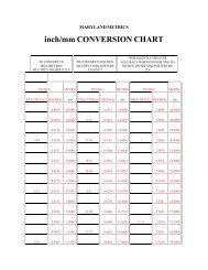
FRONTREARXS650E BASICWEIGHT with oilmd full fuel tankStandard tire104 kg@29 lb) 119 kg1262 lb)Bridgestone or Bridgestone orYokohama Yokohama3.50H19-4PR 4.OOHlB-lPRTire load limit234 kg (515 lb) 280 kg (615 lb]Cold tire pressureNormal riding 1.6 kg/cm’ 2.0 kg/cm2(22 psi) (28 psi)With passenger 2.0 kg/cm2 2.3 kg/cm’or high speed (28 psi) (32 psi)riding2.8 kg/cm2With passenger 2.8 kg/cm2$$xtra load (40 psi)(40 psi)Vlinimum tire 0.8 mm 0.8 mm:read depth (0.03 in) (0.03 in)Make sure the total weight of the motorcycle withaccessories, rider(s) etc., does not exceed the tirelimits.b. Check the tire wearIf a tire tread shows cross wise lines, itmeans that the tire is worn to its limit.Replace the tire.20 mm (3/4 in)2. Tension adjustmenta. Loosen the rear brake adjuster.b. Remove the cotter pin of the rear wheelaxle nut.c. Loosen the rear wheel axle nut.d. Loosen the adjuster lock nuts on eachside.e. To tighten chain turn chain puller adjusterclockwise.Turn each bolt exactly the same amountto maintain correct axle alignment.There are marks on each side of rear armand on each chain puller; use them tocheck for proper alignment.c. Check the wheel damage and check thetightness of spokes.G. Drive chain1. Tension checka. Inspect the drive chain with mainstanderected. Check the tension at the positionshown in the illustration. The normal verticaldeflection is approximately 20 mm(3/4 in).1. Alignment marks2. Rear axle nut3. Adjuster4. Lock nut5. Cotter pinf. After adjusting be sure to tighten the locknuts and the rear wheel axle nut.g. Install a new cotter pin and bend the endover.h. In the final step, adjust the play in the3.a.brake pedal and stoplight switch free play.LubricationFirst, remove dirt and mud from the chainwith a brush or cloth and then spray thelubricant between both rows of side platesand on all center rollers.-,I -
Ib. To clean the entire chain, first removethe chain from the motorcycle, dip it insolvent and clean with stiff brush. Thentake the chain out of the solvent and dryit. Immediately, lubricate the chain toprevent the formation of rust.7. Install drain screw.NOTE:Check gasket. Replace if damaged.8. Pour specified amount of oil into the innertube through the upper end opening.Front fork oil:Yamaha fork oil 10 WtH. Front fork oil change1. Raise the front wheel off the floor with asuitable frame stand.2. Loosen the fork pinch bolts.3. Remove the rubber cap from the top ofeach fork.Front fork oil capacity:164 - 172 cc (5.54 - 5.82 oz)each side9. After filling, slowly pump the outer tubesup and down to distribute the oil.10. Inspect O-ring on fork cap bolts and replaceif damaged.61. Pinch bolt 2. CSP4. Loosen the cap bolt (adjuster unit).5. Remove drain screw from each outer tubewith open container under each drain hole.1. O-ring11. Install fork cap bolts.12. Tighten pinch bolts.ITightening torque:Fork cap boltIm-kg ft-lb5.0 36Pinch bolt1.0 71. DreainScrewrCAUTION:Do not allow oil to contact disc brakecomponents.6. After most oil has drained, slowly raiseand lower outer tubes to pump out remaining oil.I. Steering head1. adjustmentThe steering assembly should be checkedperiodically for looseness.Do this as follows:a. Raise front end of machine so that thereis no weight on the front wheel.b. Grasp bottom of forks and gently rockfork assembly backward and forward,checking for looseness in the steeringassembly bearings.- I2 -
the end of the cable can be held high topour in several drops of lubricant. Withthrottle grip disassembled, coat the insidesurface of the throttle grip guide tubewith a suitable all-purpose grease to cutdown friction.2. Meter cablesPull the inner cable out and apply cablelube throughly.c. If there is looseness in the steering head,loosen the crown pinch bolt, fork pinchbolts, and steering fitting bolt.3. Rear arm pivot shaftApply grease to grease nipple on top ofpivot with low pressure hand operatedgun. Apply until fresh grease appears atboth ends of pivot shaft.Recommended lube:Medium-weight wheel bearing grease1. Crown pinch bolt2. Fork pinch bolt3. Steering fitting boltd. Use steering nut wrench to loosen topsteering fitting nut. The top nut serves asa lock nut.e. Tighten the lower steering fitting nut untilthe steering head is tight, but does notbind when forks are turned.f. Retighten the top steering fitting bolt,crown pinch bolts and fork pinch bolts, inthat order.g. Recheck steering adjustment to make surethere is no binding when the forks aremoved from lock to lock. If necessary,repeat adjustment procedure.2. LubricationRefer to PAGE 47.J. Lubrication of cables, pivots, etc.1. Throttle cable and gripThe throttle twist grip assembly should begreased at the time that the cable is lubricatedsince the grip must be removed toget at the end of the throttle cable. Twoscrews clamp the throttle housing to thehandlebar. Once these two are removed,4. Brake and change pedal shafts, and centerand side stand pivots Lubricate the shaftsand pivots with Yamaha chain and cablelube or SAE l0W/30 motor oil.5. Wheel bearingsRefer to PAGE 39.2-5. ELECTRICALA. Contact breaker point adjustment1.2.3.Remove breaker point cover.Check contact breaker point gap (atlargest gap) with clean feeler gauge.Contact breaker gap:0.3 - 0.4 mm (0.012 - 0.016 in)If necessary, adjust by loosening securingscrews and moving the adjustable contactpoint.Tighten adjusting screws and recheckbreaker point gap.B. Contact breaker point maintenance1. The contact breaker should be checkedfor the following:a. Wear of the bakelite cam heelb. Damage of contact point surfaces-13-
c. Rust or wear on the breaker arm or armshaft.d. Faulty insulation of the contact brakere2.3.assembly.Oil or dirt on the assembly.To clean the points, run a point file betweenthe points until the grey depositsand pits have been removed. Spray thepoints with ignition point cleaner orlacquer thinner, then snap the points shuton a white business card (or paper of hardtexture) and repeatedly pull the cardthrough until no more carbon or metalparticles come off on the card. (The cardmay be dipped in lacquer thinner or othercleaner to facilitate this procedure.)Point replacement should be necessarywhen the points become severely pitted, ifthe heel is broken or worn unevenly, or ifthe points become shorted or show faultyoperation.NOTE:New points must be cleaned and adjusted.2.3.4.5.6.7.Ignition timing of right-hand cylindermust be set first. Connect timing light toright-hand spark plug lead wire.Start engine.The mark stamped on the rotor_ shouldline up with the stationary “F” timingmark. If it does not align, loosen twobreaker backing plate screws and movethe complete backing plate until the markon the rotor and the “F” mark align.Retighten screws. Check timing again forthe right-hand cylinder.Rev the engine to above 3,500 rpm.Check whether the mark on the rotor is inthe vicinity of the stationary “full advance”mark.Repeat procedure (steps 2-6) for anothercylinder.4.Add a few drops of light-weight machineoil onto the felt rubbing pad after eachpoint adjustment to lubricate the pointcam surface. Do not over oil.C. Ignition timingNOTE:Point gap must be set before setting timing.1. Ignition timing is checked with a timinglight by observing the position of thestationary marks stamped on the statorand the pointer on the generator.1. Top dead center2. 15’ BT0C11.200 rpm3. Advanced mark_14 -1. Rlghf cylinder timing adfustment2. Left cylinder timmg adjustmentD. Carbon brushesVisually inspect the carbon brush holderbrushes for obvious breakage or wear.Standard brush length is 14.5 mm(0.571 in).Wear limit is 7.0 mm (0.276 in) andmarked there.E. BatteryA poorly maintained battery will deterioratequickly. The battery fluid should be checkedat least once a month.1. The level should be between the upperand lower level marks. Use only distilledwater for refilling. Normal tap water containsminerals which are harmful to abattery; therefore, refill only with distilledwater.2. Always make sure the connections arecorrect when installing the battery. Themagnet relay lead is for the (+) terminal
and thechassis lead is for the (-) terminal.Make sure the breather pipe is properlyconnected, properly routed, and is notdamaged or obstructed.NOTE:The battery must be charged before usingto insure maximum performance. Failureto properly charge the battery before firstuse, or a low electrolyte level, will causepremature failure of the battery.Charging current:Charging hours:1.4 Amp10 hrssent on the surface of the spark plug, andtorque the spark plug properly.Standard spark plug:Champion N-7Y or NGK BP 7ESTightening torque:2.0 m-kg (14 ft-lb)G. Headlight1. Headlight beam adjustment.When necessary, adjust the headlightbeam as follows:a. Adjust horizontally by tightening orloosening the adjust screw.F. Spark plugThe spark plug indicates how the engine isoperating. If the engine is operating correctly,and the machine is being ridden properly, thetip of the white insulator around the positiveelectrode of the spark plug will be a mediumtan color. If the insulator is very dark brown1. If the insulator is very dark brown orblack color, then a plug with a hotter heatrange might be required. This situation isquite common during the engine break-inperiod.2. If the insulator tip shows a very light tanor white color or is actually pure whiteand glazed, or if electrodes show signs ofmelting, then a spark plug with a colderheat range is required. Remember, theinsulator area surrounding the positiveelectrode of the spark plug must be amedium tan color. If it is not, checkcarburetion, timing and ignition adjustments.3. The spark plug must be removed andchecked. Check electrode wear, insulatorcolor, and electrode gap.Spark plug gap:0.7 - 0.8 mm (0.028 - 0.031 in)Engine heat and combustion chamber depositswill cause any spark plug to slowlybreak down and erode. If the electrodesfinally become too worn, or if for any reasonyou believe the spark plug is not functioningcorrectly, replace it. When installing the plug,always clean the gasket surface, use a newgasket, wipe off any grime that might be pre-- 15 -To adjust to the right:Tighten the screwTo adjust to the left:Loosen the screwb. Adjust vertically as follows:1) Loosen adjusting screw and adjust verticallyby moving the headlight body.2) Retighten the screw.1. Vertical adjustment2. Horizontal adjustment2. Replacing the headlight bulb._-_.__ --a. Loosen bolts and replace bulb.b. After installing, adjust headlight beam.NOTE:Take care not to damage the headlight. Itis very fragile.
CHAPTER 3. ENGINE OVERHAUL3-1.3-2.3-3.ENGINE REMOVAL ........................................ .... .18A. Preparation for removal ................................... .... .18B. Fuel tank removal ....................................... .... .18C. Removal of other parts. ................................... .... .I8D. Engine mounting bolts and engine removal .................... .... .18ENGINE DISASSEMBLY .................................... ..... .19A. Governor and breaker assembly removal ........ ..................... 19B. Cylinder head and cylinder removal ............ ..................... 19C. Rocker arm removal ........................ ..................... 19D. Valve removal .............................E. Piston removal .................................................19.....................19F. Generator removal ......................... ..................... 19G. Primary drive gear and clutch assembly removal ... ..................... 19H. Kick axle and change shaft removal ............ .................... .20I. Electric starter unit removal .................. ..................... 20J. Oil pump removal. ......................... ..................... 20K. Crankcase disassembly ...................... .....................20L. Transmission illustration .................... ..................... 21M. Shift drum removal ........................ ..................... 21N. Crank shaft removal ........................ ..................... 22INSPECTION AND REPAIR . . . . . . . . . . . . . . . . . . . . . . . . . . . . . . . . . . . . . . . . . . .22A.B.C.D.E.F.Cyinder head cover. ............................................... .22Cylinderhead.....................................................2 2Valve, valve guide and valve seat. ......................................23Valvespring.. .................................................. ..2 4Rocker arm and rocker shaft .........................................25Cam shaft wear ................................................ ..2 5G. Cam chain, sprocket and dampers .....................................26H. Cylinder.........................................................2 6I. Piston and rings ...................................................26J. Pistonpin........................................................2 7K. Crankshaft ..................................................... ..2 7L. Oil pump ...................................................... ..2 7M. Clutch ........................................................ ..2 8N. Transmission .....................................................2 80. Electric starter gears and clip spring ................................... .29P. Kickstarter ......................................................2 9Q. Crankcase and oil passages .......................................... .29R. Bearings and oil seals ............................................... 29
3-4. ENGINE ASSEMBLY AND ADJUSTMENT ............................ . .29A. Shift ......................................................... . .29B. Transmission and crankshaft ...................................... . .29C. Shifter assembly ................................................ . .30D. Kick starter assembly ............................................ . .30E. Electric-starter gear assembly ...................................... . .30F. Clutch ....................................................... . -30G. Generator ..................................................... . .32H. Oil pump ..................................................... . .32I. Right-hand crankcase cover ....................................... . .32J. Piston ........................................................ . .32K. Cylinder and cylinder head. ....................................... . .32L. Camshaft ..................................................... . .32M. Cylinder head cover ............................................. * -33N. Governor and breaker assembly .................................... * *330. Engine ....................................................... . .33
CHAPTER 3.ENGINE OVERHAUL31. ENGINE REMOVALA. Preparation for removal1. All dirt, mud, dust and foreign materialshould be thoroughly removed from theexterior of the engine before removal anddisassembly.2. Place machine on center stand. Star-fengine and allow it to warm up. Stopengine and drain engine/transmission oil.8. Carburetor (to the left), and throttle cable9. Brake pedal10. All wires and cables connecting engineand chassis11. Top center engine mounting brackets(Remove only four bolts for easier reassembly)B. Fuel tank removal1. Turn fuel petcocks to “on” (there is no“off” position - fuel will not flow from apetcock on the “on” position unless theengine is operating). Disconnect fuel pipesand vacuum pipes from petcock.2. Lift seat and remove fuel tank holdingbolt. Remove fuel tank.C. Removal of other partsRemove the following parts in the order given.1. Exhaust pipes2. Horn (as a unit)3. Both side footrests4. Change pedal and drive chain guide5. Left-hand crank case cover and clutchcable.6. Side covers7. Air cleaner assembly and ventilationhoses.T..--12. Drive chain (with special tool)D. Engine mounting bolts and engine removal1. Remove mounting bolts in the order as2. Remove the engine to the right.
3-2 ENGINE DISASSEMBLYA. Governor and breaker assembly removalRemove the following parts in the ordergiven.1. Breaker cover2. Breaker backing plate3. Breaker housing4. Governor cover5. Notched plate6. Lock nut (using punch and hammer)7. Governor assemblyC. Rocker arm removal1. Remove rocker shaft covers.2. Remove shouldered sleeves and O-rings.3. Withdraw rocker shafts with the specialtool or 6 mm bolt.D. Valve removal1.2.3.Compress the valve spring and then removeboth retainer locks.Remove the compressor and lift off theretainer and springs.Remove valve stem seals.Remove valves.NOTE:Deburr any deformed valve stem end. Usean oil stone to smooth the stem end. Thiswill help prevent damage to the valveguide during valve removal.8. Breaker shaft (to the point side)9. Dowel pin10. Advance unit housingB. Cylinder head and cylinder removal1. Remove the oil delivery and pipe fittingattached to the crankcase. Note placement of copper gaskets.2. Remove all tappet covers.3. Remove spark plugs.4. Remove four cylinder head cover holdingbolts, three cylinder head holding boltsand eight cylinder head holding nuts.5. Remove the head cover. It may be necessaryto tap each lightly with a softhammer.6. Remove the camshaft as follows.a. Remove tensioner adjusting bolt to makethe chain tension loose.b. Push out the master link pins with thecam chain cutter.c. Tie each end of the camchain with a wireto prevent it from falling into the crankcase.7. Remove the cylinder head and cylinder.NOTE:It is advisable to remove the stator androtor after finding the place of the masterlink pins. Refer to item “F. Generatorremoval.”E. Piston removalRemove piston pin clips, piston pins andpistons.F. Generator removal1. Remove the stator.2. Remove the securing nut and lock washer.3. Mount the rotor puller (special tool) ontothe rotor and pull the rotor off.i .’~eca9coio7ojG. Primary drive gear and clutch assembly removal1. Remove the crankcase cover (right).2. Loosen the drive gear securing nut by firstplacing a rag folded into many layers betweenthe teeth of gears to lock them.3. Remove six clutch spring screws and pressureplate.4. Remove clutch plates, friction plates,push crown, two push rods and two balls.-19-
I. Electric starter unit removal1. Remove the gear train cover, and idle gear1 and 2.1.2.3.4.Push rodBallPush rod (AluminumlPush crown5. Hold the clutch unit with the holding tool(special tool), and unscrew the clutch bosslock nut.1. Kick axle 4. Kick gear 7. Spacer 10. Washer2. Holder 5. Kickclip 8. Kickspring 11. Circlip3. Clip 6. Shim 9. Spring wide2. Remove the four mounting bolts andH. Kick axle and change shaft removal motor.1. Slip the bent spring off and pull the kick 3. Remove the panhead screw (10), gear 2axle assembly out. (6). shaft 2 (5), and gear 1 (4).2. Remove circlip from left side of change 4. Remove the circlip (11), and gear asshaftand pull the shaft out. sembly (7) (8) (9).5. Starter gears illustrationTD 2. 1. Absorber Idlegear 1 6. 7. Gear Starter 3 wheel3. ldlegear 2 9. Gear 4T g4. Gear 1 10. Panhead screw5. Shaft 2 11. CirclipY 36. Gear 2J. Oil pump removal K.Crankcase disassembly1. Remove the tachometer drive gear, oil 1. Loosen all case securing bolts and nutspump driven gear, and key.l/4 turn at a time to avoid case warpage,2. Remove the three Phillips screws. and remove them.3. Remove the pump unit. 2. Use a soft rubber hammer to carefullyseparate the crankcases.- 20 -
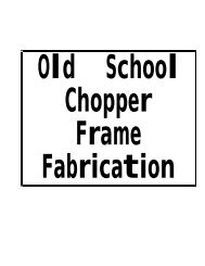
L. Transmission illustration1. Main axle (13T) 1’ 1st wheel gear (32T) Transmission2. 2nd pinion gear (17T) 2’ 2nd wheel gear (27T)3. 3rd pinion gear (20T) 3’ 3rd wheel gear (26T)4. 4th pinion gear (21T) 4’ 4th wheel gear (23T)5. 5th pinion gear (23T) 5’ 5th wheel gear (22T)6. Drive sprocket (17T)M. Shift drum removal1. Bolt2. Lock plate3. stopper Plate4. Shaft bolt5. stopper6. Stopper spring7. Shift cam8. Bearing9. Shift fork (3)10. Shift fork (2)11. Shiftfork (1)12. Pin13. Cotter pin14. Guide bar15. Cam stopper16. Stopper spring17. Gasket18. Stopper bolt
1. Release the stopper spring (6). 4. Remove the neutral detent unit (15-18).2. Remove the bolts (1) and stopper plate(3). 5. Removecotter pins (13). and pin (12)3. Pull the guide bar (14) out. 6. Pull out the shift cam (7).N. Crankshaft removal1. Tap the crankshaft with a rubber hammerto loosen it, then lift it out.2. Crankshaft illustration1. Crank 1(L) 14. Cam chain sprocket2. Crank 2(R) 15. Journal bearing 23. Crank 2(L) 16. Circlip4. Crank 2(R) 17. Primary drive gear5. Woodruff key6. Connecting rod18. Plate washer19. Drive gear7. Big end bearing 20. Dowel pin8. Crank pin washer 21. Oil seal9, 10 Crank pin 22. Spring washer11. Crankshim 23. Nut12. Journal bearing 1 24. Key25. Dowel pin33-3. INSPECTION AND REPAIRA.Cylinder head coverPlace head cover on a surface plate. Thereshould be no warpage. Correct by re-surfacingas follows:Place #400 or #600 grit wet sandpaper onsurface plate and re-surface head cover usinga figure-eight sanding pattern. Rotate headcover several times to avoid removing toomuch material from one side.B. Cylinder head1. Remove spark plugs.2. Remove valves.3. Using a rounded scraper, remove carbondeposits from combustion chamber. Takecare to avoid damaging spark plug threadsand valve seats. Do not use a sharpinstrument. Avoid scratching the aluminum.4. Place on a surface plate. There should beno warpage. Correct by re-surfacing asfollows:Place #400 or #600 grit wet sandpaperon surface plate and re-surface head usinga figure-eight sanding pattern. Rotatehead several times to avoid removing toomuch material from one side.22
C. Valve, valve guide and valve seat1. Valve guidea. If the valve guide inside diameter is beyondserviceable limits, replace with anoversize valve guide.StandardGuide diameter 1 8.010 - 8.019 mm(I.D.) (IN.EX) / (0.315 - 0.316 in)b. Measuring the clearance between valveand valve guide.1) Insert the valve into the valve guide inthe cylinder head and measure theclearance in both the X and Y axes,using a small dial gauge.1. Dial gauge2. 10 mm IO.4 in)2) If the measured clearance is greaterthan 0.10 mm (0.0039 in) for theinlet valve or 0.12 mm (0.0047 in) forthe exhaust valve, both the valve andvalve guide should be replaced. Thereplacement valve guide should be onethat is oversize.d. Use the appropriate shouldered punch(special tool) to drive the old guide outand drive the new guide in.e, After installing the valve guide, use 8 mmreamer (special tool) to obtain the properf.2.a.valve clearance.After fitting the valve guide into thecylinder head, be sure to grind the valveseat, and perform valve lapping. The valvemust be replaced with a new one.Grinding the valve seat.The valve seat is subject to severe wearsimilar to valve face. Whenever the valveface is resurfaced, the valve seat shouldalso be re-surfaced at a 45° angle. Inaddition, if a new valve guide has beeninstalled (without any valve repair), thevalve seat should be checked to guaranteecomplete sealing between the valve faceand seat.CAUTION :If the valve seat is obviously pitted or1worn, it should be cleaned with a valveseat cutter. Use the 45° cutter, andwhen twisting the cutter, keep an evendownward pressure to prevent chatterILmarks.If cutting section “A” of the valve seat,use the 8R cutter (radius cutter). Ifcutting section “B”, use the 45° cutter.Valve guide oversize:Part No.Size (0.D.)256-l 1133-l 1 (IN) 15.1 mm (0.594 in)256-l 1133-21 15.2 mm (0.598 in)256-l 1134-l 1 (EX) 15.1 mm (0.594 in)256-l 1134-21 15.2 mm (0.598 in)c. To ease guide removal and reinstallation,and to maintain the correct interferencefit, heat the head to 100°C. Use an ovento avoid any possibility of head warpagedue to uneven heating.b. Measure valve seat width. Apply mechanic’sbluing dye (such as Dykem) to thevalve face, apply a very small amount offie grinding compound around the surfaceof the valve seat, insert the valve intoposition, and spin the valve quickly backand forth. Lift the valve, clean off allgrinding compound, and check valve seat- 23
width. The valve seat will have removedthe bluing wherever it contacted the valveface. Measure the seat width with verniercalipers. It should measure approximately1.3 mm. Also, the seat should be uniformin contact area. If valve seat width varies,or if pits still exist, then continue to cutwith the 45° cutter. Remove just enoughmaterial to achieve a satisfactory seat.Standard widthWear limitI I / Ic. If the valve seat is uniform around theperimeter of the valve face, but is toowide or not centered on the valve face, itmust be altered. Use either the 8R, 45°or 25° cutters to correct the improperseat location in the manner describedbelow:1) If the valve face shows that the valveseat is centered on the valve face, buttoo wide, then lightly use both the 8Rand the 25° cutters to reduce the seatwidth to 1.3 mm.2) If the seat shows to be in the middleof the valve face, but too narrow, usethe 45° cutter until the width equals3)4)1.3 mm.If the seat is too narrow and right upnear the valve margin, then first usethe 8R cutter and then the 45° cutterto get the correct seat width.If the seat is too narrow and downnear the bottom edge of the valveface, then first use the 25° cutter andthen the 45° cutter.I I ’ I3. Lapping the valve/valve seat assembly.a. The valve/valve seat assembly should belapped if (1) neither the seat nor the valveface are severely worn, or (2) if the valveface and valve seat have been resurfacedand now require a final light grindingoperation for perfect sealing.Apply a small amount of coarse lappingcompound to valve face. Insert the valveinto the head. Rotate the valve until thevalve and valve seat are evenly polished.Clean off the coarse compound, thenfollow the same procedure with fine compound.Continue lapping until the valve faceshows a complete and smooth surface allthe way around. Clean off the compoundmaterial. Apply bluing dye to the valveface and rotate the valve face for full seatcontact which is indicated by a shiny surfaceall around the valve face where thebluing has been rubbed away._. Valve leakage checkAfter all work has been performed on thevalve and valve seat, and all head partshave been assembled, check for propervalve/valve seat sealing by pouring solventinto each of the intake ports, then theexhaust ports. There should be no leakagepast the seat. If fluid leaks, disassembleand continue to lap with fine lappingcompound. Clean all parts thoroughly,reassemble and check again with solvent.Repeat this procedure as often as necessaryto obtain a satisfactory seal.D. Valve spring1. Checking the valve springsa. This engine uses two springs of differentsizes to prevent valve float or surging. Thechart below shows the basic valuecharacteristics.b. Even though the spring is constructed ofdurable spring steel, it gradually losessome of it’s tension. This is evidenced bya gradual shortening of free length. Use avernier caliper to measure spring freelength. If the free length of any spring has24 ~decreased more than 2 mm (0.08 in) fromits specification, replace it.
c. Another symptom of a fatigued spring isinsufficient spring pressure when compressed.This can be checked using a valvespring compression rate gauge. Test eachspring individually. Place it in the gaugeand compress the spring first to thespecified compressed length with the valveclosed (all spring specifications can befound in the previous section, valvespring), then to length with the valveopen. Note the poundage indicated on thescale at each setting. Use this procedurewith outer springs, then the inner spring.NOTE:All valve springs must be installed withgreater pitch upward as shown.1. Larger patch2. Smaller pitchd. Valve spring specifications/Ivalve closed) (1.457 ml (1.378 m)Compressed 53.5 - 61.5 kg 25.5 - 29.0 kgE. Rocker arm and rocker shaft.1. The rocker arm usually wears at twolocations: (1) at the rocker shaft hole, (2)at the cam lobe contacting surface.2. Measure the rocker shaft hole in therocker arm.- 25Standard size:15.000 ~ 15.018 mm(0.5906 ~ 0.5913 in)3. The shaft has been hardened and it shouldnot wear excessively. If a groove hasdeveloped in this surface that can be felt,or if it shows a blue discoloration, thenthe shaft should be replaced and thelubrication system (pump and passages)checked.Standard shaft diameter:14.985 ~ 14.991 mm(0.5900 ~ 0.5902 in)4. Standard clearance between the rockershaft and hole should be 0.009 ~ 0.033mm (0.00035 ~ 0.00130 in). If measurementshows more than 0.1 mm (0.0004in) clearance, replace either or both partsas necessary.F. Camshaft wear1. The cam lobe metal surface may have a2.3.blue discoloration due to excessive friction.The metal surface could also start toflake off or become pitted. This is due topoor lubrication, incorrect clearances(from poor adjustment or valve bounce),or due to normal wear.If any of the above wear conditions arereadily visible, the camshaft should be replaced.Also, the corresponding rockerarm contacting surface should be checkedfor similar wear and replaced if obviouswear is noted.Even though the cam lobe surface appearsto be in satisfactory condition, the lobesshould be measured with a micrometer.Cam lobe wear can occur without scarringthe surface. If this wear exceeds a predeterminedamount, valve timing and liftare affected. Replace the camshaft if wearexceeds the limits listed below.IntakeCam Lift (A) Width (6)Standard Value Wear Llmtt Standard Value Wear Llmat39.99+0.05 mm 39 84 mm 32.24kO.05 mm 32.09 mm(1.574+0.002 in1 IO.569 1n1 ‘II 269f0.002 In) (1.263 m)Exhaust 40 03_+0.05 mm 139.88 mm 32.30+0.05 mm 32.15 mm11.576+0.002 1n1 i11.570 in) 11.272+0 002 in1 (1.266 in)
Q -t- -7IB4. All camshaft bearings should be removed,cleaned, dried, and the races visuallychecked for pits, rust spots or chattermarks where the balls have dragged, Ifany of these conditions exists the bearing(s)should be replaced.G.Cam chain, sprocket and dampers1. Cam chainExcept in cases of oil starvation, the camchain wears very little. If the cam chainhas stretched excessively and it is difficultto keep the proper cam chain tension, thechain should be replaced.2. Cam sprocketsCheck cam sprockets for obvious wear.3. Cam chain dampersInspect the two vertical (slipper-type)dampers for excessive wear. Any thatshows excessive wear should be replaced.Worn dampers may indicate an improperlyadjusted or worn-out cam chain,H. Cylinder1. Inspect the cylinder walls for scratches. Ifvertical scratches are evident, the cylinderwall should be rebored or the cylindershould be replaced.2. Measure cylinder wall wear as shown. Ifwear is excessive, compression pressurewill decrease. Rebore the cylinder walland replace the piston and piston rings.Cylinder wear should be measured atthree depths with a cylinder bore gauge.(See illustration.)AI I Standard Wear Ilmit I1 Cylinder/ outof-roundIf the cylinder wall is worn more thanwear limit, it should be rebored.I. Piston and piston rings1. Pistona. Measure the outside diameter of thepiston at the piston skirt.Measurement should be made at a point10 mm (0.394 in) above the bottom edgeof the piston. Place the micrometer atright angles to the piston pin.Standard:Oversize 1:Oversize 2:Oversize 3:Oversize 4:74.96, 74.97 mm(2.951, 2.952 in)75.25 mm (2.963 in)75.50 mm (2.972 in)75.75 mm (2.982 in)76.00 mm (2.992 in)26
. Determine piston clearance as follows:Example:75.02 mm-74.97 mm=0.05 mm piston clearancec. Piston ring/ring groove fit must havecorrect clearance. If the piston and ringhave already been used, the ring must beremoved and the ring groove cleaned ofcarbon. The rings should then be reinstalled. Use a feeler gauge to measure thegap between the ring and the land.;I(0.0016Q.0031 in1 10.0012 -0.0028 in)2. Piston ringa. The oversize top and middle ring sizes arestamped on top of the ring.1’J. Piston pin1. Apply a light film of oil to pin. install inconnecting rod small end. Check for play.There should be no noticeable vertical2.play. If play exists, check connecting rodsmall end for wear. Replace pin and connectingrod as required.The piston pin should have no noticeablefree play in piston. If the piston pin isloose, replace the pin and/or the piston.K. Crankshaft1. Main bearing and big end bearing visuallyinspect all friction surfaces for obviouspits, scratches, chatter marks, or rust. Replaceit if necessary.2. Small end play(A)Maximum allowable tolerance:2.0 mm (0.079 in)3. Big end side clearance(B)Standard clearance:0.15 - 0.4 mm (0.0059 - 0.016 in)4. Crankshaft run out(C)Mount the crankshaft in V-blocks andcheck for run out using a dial gauge.1Run out limit: 0.05 mm (0.002 in)b. Push the ring into the bore and check endgap clearance with a feeler gauge.NOTE:The end gap on the expander spacer ofthe oil control ring is unmeasureable. Ifoil control ring rails show excessive gap,all three components should be replaced.StandardLimitTopl2nd 0.2 7 0.4 mm 1.0 mmring (0.0079 - 0.016 in) (0.039 in)Oil control 0.2 - 0.9 mm Visual(Rails) (0.0079 - 0.0354 in) inspectionL. Oil pump1. Check the clearance between housing andouter rotor.Standard clearance:0.10 - 0.18 mm (0.0039 - 0.0071 in)- 27 -
2. Check the clearance between outer rotorand inner rotor.Standard clearance:0.03 - 0.09 mm (0.0012 - 0.0035 in)M. Clutch1. Clutch housingCheck dogs on clutch housing. Look forcracks and signs of galling on edges. Ifdamage is moderate, deburr. If severe, replaceclutch housing.NOTE:Galling on the friction plate dogs of theclutch housing will cause erratic clutchoperation.2. Clutch bossCheck splines on clutch boss for galling. Ifdamage is slight to moderate, deburr. If itis severe, replace clutch boss.NOTE:Galling on clutch plate splines will causeerratic clutch operation.3. Friction and clutch platesCheck clutch steel plates and frictionplates for heat damage. Measure frictionplate thickness at 3 or 4 points. Measureclutch plates for warpage. Replace clutchplate or friction plates as a set if any isfaulty or beyond wear limits.Friction platethicknessClutch platewarp limitStandard3.0 mm(0.118 inl-Wear limit2.7 mm(0.106 in)0.05 mm(0.002 in)4. Clutch push rodCheck ends of clutch push rod for indentation.If severe, clutch adjustment maybe difficult. Check for looseness of thesteel ends of the push rod. If ends areloose or indented, replace push rod.5. Clutch springsMeasure clutch spring free length. Replacesprings as a set if necessary.Clutch spring length:34.6 mm (1.362 in)N. Transmission1. Inspect each shift fork for signs of gallingon gear contact surfaces. Check for bending.Make sure each fork slides freely onits guide bar.2. Roll the guide bar across a surface plate.If bar is bent, replace.3. Check the shift cam grooves for signs ofwear or damage. If any profile has excessivewear and/or damage, replace cam.4. Check the cam followers on each shiftfork for wear. The follower should fitsnugly into its seat in the shift fork, butshould not be overly tight. Check the endsthat ride in the grooves in the shift cam. Ifthey are worn or damaged, replacefollowers.5. Check shift cam dowel pins and side platefor looseness, damage or wear. Replace asrequired.6. Check the shift cam stopper plate and circlipand stopper for wear. Replace as required.7. Check the transmission shafts using acentering device and dial gauge. If anyshaft is bent beyond specified limit, replaceshaft.I8.9.10.Maximum run-out:0.03 mm (0.001 in) ICarefully inspect each gear. Look forsigns of obvious heat damage (blue discoloration).Check the gear teeth for signsof pitting, galling or other extreme wear.Replace as required.Check to see that each gear moves freelyon its shaft.Check to see that all washers and clips areproperly installed and undamaged. Replacebent or loose clips and bent washers.
11. Check to see that each gear properlyengages its counterpart on the shaft.Check the mating dogs for rounded edges,cracks, or missing portions. Replace asrequired.0. Electric starter gears and clip spring1. Check the gears for wear or scratches onteeth, particularly in the chamfered areaof each gear.2. The clip spring is fitted to gear (4) (Referto PAGE 20) and slides in the groove. Atoo-tight or loose-fitting clip may result inimproper operation. If too loose, bend theclip so that the friction increases, or replaceclip.Friction tension:2.2 - 2.5 kg (4.9 - 5.5 lb)P. Kick starter1. Kick gearsCheck the kick gears for wear or scratcheson teeth, particularly in the chamferedarea of each gear.2. Kick clip springThe kick clip is fitted to kick gear andslides in the groove. A too-tight or loosefittingclip may result in improper operation.If too loose, bend the kick clip sothat the friction increases, or replace clip.Friction tension:1.2 - 1.7 kg (2.0 - 3.7 lb)Q. Crankcases and oil passages1. Check crankcases for cracks or otherdamage.2. Clean all oil passages and blow out withcompressed air.R. Bearings and oil seals1. After cleaning and lubricating bearings,rotate inner race with a finger. If roughspots are felt, replace the bearing.2. Check oil seal lips for damage and wear.Replace as required.3-4. ENGINE ASSEMBLY AND ADJUST-MENTNOTE:1) All gaskets and seals should be replacedwhen an engine is overhauled. All gasketsurfaces must be cleaned.2) Properly oil all mating engine and transmissionparts during assembly.3) All circlips should be inspected beforeassembly. Replace distorted circlips.Always replace cotter pins and piston pinclips after one use.A. Shift(Refer to PAGE 21)Install shift forks, shift cam, guide pin, cotterpin, guide bar, stoper plate and detent. ApplyLOCK-TITE to eccentric bolt.NOTE:Check for smooth and complete shifting afterinstalling transmission.B. Transmission and crankshaft1. Rotate shift cam to neutral position.2. Install the transmission, bearings and sealsonto the upper case.3. Install crankshaft, seal and bearings.NOTE:Fit each bearing over each locating pinand push the crankshaft into position byhand. Each bearing has line or punchmark which indicates the position ofmating surface.- 29 -
4. Make sure all bearings are positioned properlyas shown.1. No clearance5. Fit the chain over the cam sprocket,6. Apply Yamaha Bond No. 4 sealant tocrankcase mating surface.7. Install bottom crankcase and nuts. Installnuts as follows:a. Use copper washers and blind nuts onbolts (1). (2), (3), (4), (12), (13).b. Tighten nuts in two stages in proper torquesequence. Start with bolt number one.1. Kick clap2. Positioning the kick clip in the groove,rotate the kick axle by kick lever l/2 turncounterclockwise.3. Push the axle in.4. Check for correct operation.E. Electric-starter gear assemblyInstall the unit as shown.(Refer to PAGE 20, if necessary.)Crankcase torque:2.2 m-kg (16 ft-lb)NOTE:Before installing crankcase, make sureelectric starter shaft 2 and gear 1 (PAGE 20)is installed.C. Shifter assembly1. Install shift shaft. Install circlip (E-clip)on left side of crankcases.2. Make sure distances A and B are equal.Adjust them by adjuster if necessary.! ‘*-)]I1. ClipF. Clutch1. Install the following parts in the ordergiven.a. Plate 1, t = 1 mm (0.039 in)b. Plate 2, t = 2 mm (0.079 in)c. Spacer shaftd. Housinge. Bearing plate, t = 1 mm (0.039 in)f. Bearingg. Plate 2, t = 2 mm (0.079 in)h. Clutch bossi. Plane washer, t = 2.6 mm (0.102 in)j. Conical springk. Nut (using special tool)1. Adjuster 2. A=BD. Kick starter assembly1. Partially insert the assembly until the returnspring can be slipped over its anchorpoint.Clutch lock nut torque:6.5 m-kg (47 ft-lb)I. Friction plates and clutch platesm. Push rods, balls and push crown- 30 -
n. Pressure plate and clutch springs o. Primary drive gearClutch screw torque:Drive gear torque:/ 1 .O m-kg (7 ft-lb) 9 m-kg (65 ft-lb)Ia. Plate 1b. Plate 2C. Spacer shaftd. Housinge. Bearing platef. Bearingg. Plate 2h. Clutch bossi. Plane washerj. Conical springk. Nut (usmg special tool)I. Friction plates and clutch platesm. Push rods, balls and push crw,”n. Pressure plate and clutch springkma = 1 .o mmb =2.0e = 1.0f = 2.0g =2.0I = 2.6i = 2.0d -
G. Generator1. Lock the crank rotation at the primarydrive gear.2. Reverse the generator removal sequence.H. Oil pumpReverse the oil pump removal sequence.2. Install pistons on rods. The arrow on thepistons must point to the front of theengine.NOTE:Always install new piston pin clips.2.3.4.K. Cylinder and cylinder head1. Install the tensioner cushion onto crankcase.Install a new cylinder base gasket.Install cylinder using special tool.Install the cylinder head gasket andcylinder head.I. Right-hand crankcase coverWhile properly engaging oil pump gear, installnew case cover gasket and right-hand crankcasecover. Tighten holding screws graduallyuntil proper torque is reached.Crankcase cover holding screw torque:1.0 m-kg (7 ft-lb)L.1.2.NOTE:The assembly of the cylinder head is thereverse of the disassembly procedure.Install valve springs with tighter windings(smaller pitch) down,CamshaftRotate the piston to TDC.Install the, chain onto the camshaft withno slack in the cam chain on the frontportion (opposite side from the tensioner).tJ. Piston1, Position piston rings as shown.NOTE:1) Make sure ends of oil ring expandersare not overlapped.2) Manufacturer’s marks or numbersstamped on the rings are on the topside of the rings. Coat pistons and ringswell with oil.1. Center2. No clearance3. Position the groove in the left side of thecam sprocket so that it lines up with thesprocket centers.ii! ‘1.1. TOP2. 2nd3. Expander4. spacer upper5. spacer lower- 32 -
4. Joint the chain together and revet a newlink.5. Install the cam chain tensioner, and adjustchain tension. Refer to PAGE. (8).6. Make sure the timing is correct.O. EngineM. Cylinder heed cover1. Install all components in the head cover.2. Apply Yamaha No. 4 sealant to covermating surfaces.3. Install all head cover retaining nuts andbolts and thread them down until lightlyseated.4. Tighten them with torque wrench in theorder given111. 4 5 (M10).5.0 m-kg (36 ft-lb)N. Governor and breaker assemblyReverse the governor and breaker removalsequence.NOTE:Before inserting the governor rod, supportivebearings should be lubricated with molybdenumdisulfide.
CHAPTER 4. CARBURETION4-1. CARBURETOR.................................................... ..3 6A. Description.......................................................3 6B. Specifications.....................................................3 6C. Disassembly.......................................................3 6D. lnspecition.. ................................................... ..3 6E. Adjustments ......................................................37
41. CARBURETORA. DescriptionAir flow through the venturi is controlled bya throttle slide (vacuum piston). The slide israised and lowered by engine vacuum ratherthan a cable linked directly to the throttlegrip.B. SpecificationsMain jetJet needleNeedle jetStarter jetFuel valve seatPilot jetFuel level#135502-3z-2#a02mm#27.524*1 mm(0.94+0.04 in)(above gasket surface)NOTE: 7.The low speed mixture screw settings areadjusted at the factory with the use of specializedequipment. Do not attempt to changethese settings.8.C. Disassembly1. Prepare to separate carburetors (separationnot necessary if only float level2.3.4.adjustment or throttle value inspection isto be done). Remove starter lever. Loosenstarter lever securing screws and removestarter lever rod.Remove upper and lower brackets. Noteposition of synchronizing screws forguidance in reassembly. Separate carburetors.Remove vacuum chamber cover. Removethe spring, needle fitting clip, needle,and diaphragm (piston valve).Note that there is tab on the rubberdiaphragm. There are matching recessesin the carburetor body for the diaphragmtab.5.6.To inspect starter jet, remove three (3)screws holding the starter body to the rightside of the carburetor.Remove the four screws holding the floatbowl cover. Remove float bowl cover. Themain jet is located under a cover in thefloat bowl.Pull out float pivot pin. Remove the floatassembly. Be careful not to lose the floatvalve needle located under the float leveladjustment tongue. Remove the needlejet.Reassemble in reverse order. Pay closeattention to the installation of thevacuum piston diaphragm.D. Inspection1. Examine carburetor body and fuel passages.If contaminated, wash carburetor inpetroleum-based solvent. Do not usecaustic carburetor cleaning solutions.Blow out all passages and jets with compressedair.2. Examine condition of floats. If floats areleaking or damaged, they should be replaced.3. Inspect inlet needle valve and seat forwear or contamination. Replace thesecomponents as a set.4. Inspect piston valve and rubber diaphragm.If the piston is scratched or thediaphragm is torn, the assembly must bereplaced.- 36 -
E. Adjustments1. Float level adjustmentMeasure the distance from the bottom ofthe float to the float bowl gasket surface.Bend the tongue on the float arm if anyfloat level adjustment is necessary. Bothfloats must be at the same height. If thefuel level is too high, a rich air/fuel mixturewill occur. If too low, a lean mixturewill result.I1. Tongue A. 24+1 mm (0.94f0.04 in1- 3 7 -
5-1.5-2.5-3.5-4.5-5.5-6.5-7.5-8.5-9.5-10.CHAPTER 5. CHASSISFRONT WHEEL ...................A. Removal .......................B. Front axle inspection .............C. Front wheel inspection. ...........D. Replacing wheel bearings ..........E. Installing front wheel .............REAR WHEEL ..................... . .. . .. . .. . .. . .. * .. . .. . . .. . . .. . . .. . . .. . . .. . . .. . . .................... . .39..................... 39..................... 39..................... 39..................... 39..................... 39..................... 40A. Removal ............................................... . . . . * .40B. Rear axle inspection ...................................... . . . . . .40C. Replacing wheel bearings .................................. . . . . . .40D. Rear wheel inspection .................................... . . . . . -40E. Installing rear wheel ...................................... . . . . . .40F. Rear wheel illustration .................................... . . . . . .40BRAKES ......................................................... ..4 0A. Caliper pad replacement .............................................40B. Caliper disassembly. ............................................... .42C. Master cylinder disassembly ..........................................42D. Brake inspection and repair ..........................................42E. Brake reassembly ..................................................43WHEELS, TIRES, TUBES......................................... .. .44A. Wheel inspection ..................................................44B. Tire, tube removal ................................................ .44C. Installation .......................................................44REAR WHEEL SPROCKET ............................................44FRONT FORKS ................................................... ..4 5A. Removal and disassembly ............................................466. Inspection ..................................................... ..4 6C. Assembly ...................................................... ..4 6STEERING HEAD ......................................... ..~.......4 7A. Adjustment .................................................... ..4 7B. Removal.........................................................4 7C. Inspection ..................................................... ..4 7D. Reassembly .................................................... ..4 7SWING ARM........................................................47A. Inspection ..................................................... ..4 7B. Swing arm removal .................................................4.8C. Swing arm lubrication ..............................................48REAR SHOCK ABSORBER ............................................48A. Removal ..........................................................B. Inspection ....................................................... .CABLES AND FITTINGS .............................................48A. Cablemaintenance .............................................. ...48B. Throttle maintenance ...............................................48- 38 -
CHAPTER 5.CHASSIS5-l. FRONT WHEELA. Removal1. Remove cotter pin from front axle nut.2. Remove the front axle nut.3. Loosen the two axle holder nuts atthe bottom of the fork leg.4. Raise the front wheel of the machine byplacing suitable stand under the engine.5. Remove the front wheel axle by simultaneouslytwisting and pulling out on theaxle. Then remove the wheel assembly.The speedometer gear unit housing mustbe removed.a) If the run out is up and down, loosenspokes opposite the high spot and tightenthe spokes at the high spot.b) If the run out is sideways, loosen thespokes at the high spot, and tightenthe spokes opposite the high spot.D. Replacing wheel bearingsIf the bearings allow play in the wheel hub orif wheel does not turn smoothly, replace thebearings as follows:1. Clean the outside of the wheel hub.2. Drive the bearing out by pushing thespacer aside and tapping around theperimeter of the bearing inner race with asoft metal drift pin and hammer. The3.spacer “floats” between the bearings. Bothbearings can be removed in this manner.To install the wheel bearing, reverse theabove sequence. Be sure to grease thebearing before installation. Use a socketthat matches the outside race of the bearingas a tool to drive in the bearing.B. Front axle inspectionRemove any corrosion from axle with emerycloth. Place the axle on a surface plate andcheck for bends. If bent, replace axle.C. Front wheel inspection1. A rim can develop warpage. It is due to(1) running the wheel into an object andbending the outer rim, or (2) one or morespokes loosening.2. Check for warpage by mounting the wheelon a stand (or, if the wheel is attached toa motorcycle, it can be blocked up andheld in place). Use some device to measureor detect movement then slowly spin thewheel and note the amount of rim “runout”.It should not exceed 2 mm(0.08 in).3. If all the spokes are tight, and the rimshows no obvious signs of damage, andyet run out is still excessive, do the following:E. Installing front wheelWhen installing front wheel, reverse the removalprocedure. Note the following points:1. Lightly grease lips of front wheel oil sealsand gear teeth of speedometer drive anddriven gears. Use lightweight lithium soapbase grease.2. Make sure there is enough gap betweendisc pads.3. Check for proper engagement of the bosson the outer fork tube with the locatingslot on speedometer gear unit housing.4. Always secure the front wheel axle asfollows:a Tighten the front axle nut.Axle nut torque:8.5 m-kg (61 ft-lb)J,
. Tighten axle holder nuts. First tighten nuton front end of axle holder, then tightennut on rear end.Holder nut torque:1 .O m-kg (7 ft-lb)E. Installing rear wheel1. Lightly grease lips of rear wheel oil seals.2. To install the rear wheel, reverse theremoval procedure.NOTE:Always use a new cotter pin on the axlenut.c. install a new cotter pin.Torque:5-2. REAR WHEEL Axle nut: 15 m-kg(l08 ft-lb)A. Removal1. Place machine on center stand.2. Disconnect the tension bar, and the brakerod from the rear shoe plate. Pay strictattention to the presence and location ofthe tension bar lock washer and cotterkey. These are safety parts and must beincluded during assembly.F. Rear Wheel lubrication (on page 41)5-3. BRAKESCAUTION:Disc brake components rarely require disassembly.Do not disassembly componentsunless absolutely necessary. If any hydraulicconnection in the system is opened, the entiresystem should be disassembled, drained,cleaned and then properly filled and bledupon reassembly.CAUTION:DO not use solvents on brake internal components.Solvents will cause seals to swell anddistort. Use only clean brake fluid for cleaning.Use care with brake fluid. Brake fluid isinjurious to eyes and will damage painted surfaces.L2.3.4.5.6.Loosen the chain tension adjusting nutsand bolts on both right and left sides.Remove the rear axle cotter pin and nut.Remove the right-hand chain adjuster anddistance collar.Remove the rear brake plate.Lean the machine to the left and removethe rear wheel assembly.A.Caliper pad replacement1. It is not necessary to disassemble thebrake fluid hoses to replace the brakepads.2. Remove the caliper suppdrt bolt.*3. Remove the phillips screw that holds thebrake pads.B. Rear axle inspection(See front Wheel, Axle Inspection Procedure.)C. Replacing wheel bearingsRear wheel bearing replacement is similar tothe procedure for the front wheel.D. Rear wheel inspection(See Front Wheel, Inspection Procedures.)1. Caliper wppcm bolt2. Pad screw4. Pull caliper cylinder off caliper frame.5. Install new brake pads. Replace pads as aset.-40 -
B. Caliper disassembly1. Remove caliper brake hose. Allow caliperassembly to drain into a container.2. Place the open hose end into the containerand pump the old fluid out of themaster cylinder.3. Remove caliper support bolt and pad securingscrew as in Caliper pad replacementprocedure.4. Remove caliper assembly from caliperframe.5. Remove retaining ring and dust seal.6. Carefully force the piston out of the calipercylinder with compressed air. Nevertry to pry out the piston.that piston does not cause injury as it isexpelled from the cylinder.7. Remove piston seal.3. Remove brake lever and spring.4. Remove master cylinder from handlebars.Remove cap and drain remaining fluid.1. Snap ring2. Cylinder CUP IFI)3. Piston4. Shim5. Piston cup6. Spacer7. Return spring& h%;&D.Brake inspection and repair1 & &Recommended Brake Component ReplacementSchedule:Brake pads . . . . . . . . . . . . . . . .As requiredPiston seal, dust seal . . . . . Every two yearsBrake hoses . . . . . . . . . .Every four yearsBrake fluid . . . . . . . . . . Replace only whenbrakes are disassembledPad screw 3. sntm2. Shim 4. Pads.1. Replace caliper piston if it is scratched.2. Replace any brake pad worn beyondlimits.Replace brake pads as a set._C. Master cylinder disassembly1. Remove brake hose.2. Remove front brake switch.CAA : Pad thickness6. : Wear limit (1.5 mm)C : Wear indicator(red line)?l_Pad\Back plate
See “Caliper Replacement Pad” procedurefor parts to be replaced when pads arereplaced.cap, boot bushing, piston seal, dust seal,retaining ring.3.4.5.6.Replace piston and dust seals if damaged.Inspect master cylinder body. Replace ifscratched. Clean all passages with newbrake fluid.Inspect brake hoses. Replace every fouryears or if cracked, frayed or damaged.Check for wear and deflection of disc.Wear limit:1.5 mm (0.06 in)I_1. Bleed screw (with cap) 4. Dust seal2. Bush boot 5. Retaining ring3. Piston seala. Install piston seal and piston. Place calipercylinder into caliper frame.b. Install pad spring and retainer. Install dustseal and clip.c. Install pad spring and pads.d. Install support bolt and remount caliperon brackets.1. Dial gaugeMaximum deflection: 0.15 mm(0.006 in)Minimum disc thickness: 6.5 mm(0.26 in)1. Mounting boltMounting bolt torque:3.5 m-kg (25 ft-lb)aIf disc is worn beyond minimum thicknessor deflection exceeds specified amount,replace disc.E. Brake reassemblyAll internal parts should be cleaned innew brake fluid. Internal parts should belubricated with brake fluid when installed.2.Caliper reassemblyReplace the following parts whenever acaliper is disassembled: bleed screw and3.4.Attach brake hoses.Master cylinder reassemblyReassemble master cylinder.
5. Brake disc assemblyIf brake disc has been removed from hubor is loose, tighten bolts. Use new lockingwashers and bend over locking tabs afterbolts are tightened.[I6. Air bleeding-CAUTION:If the brake system is disassembled or ifany brake hose has been loosened or removed,the brake system must be bled toremove air from the brake fluid. If thebrake fluid level is very low or brakeoperation is incorrect, bleed the brakesystem.a. Add proper brake fluid to the reservoir.Install the diaphragm, being careful notto spill or overflow the reservoir.b. Connect the clear plastic tube tightly tothe caliper bleed screw. Put the end of thetube into a container.C. Slowly apply the brake lever several times.Pull in lever. Hold lever in “on” position.Loosen bleed screw. Allow the lever totravel slowly toward its limit. When thelimit is reached, tighten bleed screw.d. Continue step C until all air bubbles areremoved from system.NOTE:If bleeding is difficult, it may be necessaryto let the brake system stabilize for a fewhours. Repeat bleeding procedure.3. Use two wide, flat tire irons with roundededges to work the tire bead over the edgeof the rim, starting 180” opposite thetube stem. Be careful not to pinch thetube as you do this.4. After you have worked on side of the tirecompletely off the rim, slip the tube out.Be very careful not to damage the stemwhile pushing it back out of the rim hole.NOTE: __If you are changing the tire itself, thenfinish the removal by working the secondbead off the rim.C. InstallationReinstall the tire and tube by reversing thedisassembly procedure. After the tube hasbeen installed, but before the tire has beencompletely slipped onto the rim, put a smallamount of air into the tube. This removes anycreases that might exist. Release the air andcontinue with reassembly. After the tire hasbeen completely slipped onto the rim, makesure the stem comes out of the hole in the rimat a right angle to the rim. Finally inflate thetire. Refer to PAGE (10).INormal ridingFront Tire Rear Tire1.6 kg/cm* (22 psi) 2.0kg/cm2 (29psijNOTE:Make sure the wheel is balanced every timethe tire is replaced. (Refer to “Front wheelinspection”.)5-4. WHEELS, TIRES, TUBESA. Wheel inspectionWheels should be inspected frequently. Wheelrun-out is discussed in Chapter 5-1.B. Tire, tube removal1. Remove valve cap, valve core and valvestem lock nut.2. When all air is out of tube, separate tirebead from rim (both sides) by stepping ontire with your foot.5-5. REAR WHEEL SPROCKET1. Bend the lock washer ears flat.2. Remove the sprocket mounting bolts.Check the lock washer and bolt fordamage. If the lock washer is not bentover the hexagon bolt head, or is broken,or the bolt is loose, the sprocket can comeloose.
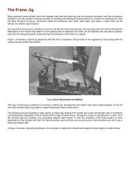
NOTE:Be sure that all lock tabs are not crackedWear limit 3 mm (0.02 in)3or broken and that they are all bent UPagainst the bolts.Constant friction and force from thechain creates wear on the sprocket teeth.If wear has progressed to the extentshown in this illustration, replace thesprocket.Slip off5-6. FRONT FORKS--_w--J’ I/26. Nutii‘0u2/I/31I30 I:d it7 It- 2 7 I’I126_ _ - J-45 -
A. Removal and disassemblyNOTE:For fork oil replacement only, refer to PAGE(12)1.2.3.4.Disconnect speedometer cable. Disconnectbrake calipers and remove front wheel.Place wooden wedge or other object intocaliper assemblies to keep brake padsapart. Remove front fender.Loosen pinch bolts on steering stem andcrown and remove fork.Remove fork tube caps, spring stopperseats, and oil drain screws. Drain fork oil.Remove Allen bolt from bottom of forkassembly. Pull inner tube out of outertube.B. inspection1. Examine fork inner tube for scratches andstraightness. If the tube is scratched severelyor bent, it should be replaced.2. If the lips of the oil seal are worn, or theoil seal is leaking, replace it.3. Check the outer tube for dents. If anydent causes the inner tube to “hang up”during operation, the outer tube shouldbe replaced.4. Check the free length of the springs.5.Spring free length:482 mm (18.98 in)Check the O-ring on the top spring seat. Ifdamaged, replace O-ring.5. To remove fork seal, pull off dust cover.Remove spring clip over oil seal. Pry outoil seal, being careful to not damage thefork tube.1.O-ring6C. Assembly1. Make sure all components are clean beforeassembly.2. Apply oil to the fork seal and install theseal spacer and seal by pressing in with alarge socket. Install retaining clip.3. Install inner tube into outer tube. Installdust cover. Install and tighten Allen boltand washer. Assembly procedure is thereverse of the disassembly procedure.NOTE:When installing fork springs, the greaterpitch should be at the bottom.
D. Reassembly1. Grease bearings and races with wheel bearinggrease.1. Bottom2. TO P5-7. STEERING HEADA.Adjustment(See Chapter 2-4 for Steering Head Adjustment.)B. Removal1.2.3.Remove front wheel, front forks andhandle bars.Remove front brake pipe junction.Loosen steering stem (underbracket)pinch bolt. Remove stem bolt and washer.Install steering stem (underbracket) andbearings.Install bottom fitting nut. Tighten toapproximately 2.0 - 2.6 m-kg (14 - 19ft-lb). Do not over-tighten. Tighten topfitting nut.Continue reassembly in reverse assemblyorder.When assembly is complete, check steeringstem by turning it from lock to lock.If threr is any binding or looseness, readjuststeering stem tightness.Under bracket.1. Crown Dlnch bolt 2. Fork pinch bolt3. Steering fitting bolt4. Remove steering crown.5. Remove top fitting nut. Use properspanner.6. Support steering stem (underbracket) andremove bottom fitting nut.7. Remove bearings.5-8. SWING ARMA. Inspection1. Free play inspectionRemove rear wheel and shock absorbers.Grasp the swing arm and move it fromside to side as shown. There should be nonoticeable side play.C. Inspection1. Wash bearings in solvent.2. inspect bearings for pitting or otherdamage. Replace bearings if pitted ordamaged. Replace races when bearings arereplaced.3. Clean and inspect bearing races. If racesare damaged, replace races and bearings.4. Install bearings in races. Spin bearings. Ifthe bearings hang up or are not smooth intheir operation in the races, replace bearingsand races.I1Swing arm freeplay: 1 mm (0.4 in)2. If freeplay is excessive, remove swing armand replace swing arm bushing.47 -I
B. Swing arm removal1. Remove nut on swingtap out bolt with abrass rod.arm pivot bolt andlong aluminum orNOTE:Carefully remove the arm while noting thelocation of spacing washers and shims.1 Pivot bolt torque: 6.5 m-kg (47 ft-lb) 12. Tap out old bushing from each side ofpivot using the long rod.3. Install new bushings using a press.NOTE:If tapping on bushing, bushing may bebroken.C. Swing arm lubrication1. Apply grease to grease fitting on top ofpivot with low pressure hand operatedgun. Apply until fresh grease appears atboth ends of pivot shaft.Recommended lubricant:Medium-weight grease2. Wipe off excess grease.1. Grease fitting5-9. REAR SHOCK ABSORBERA. RemovalRemove one (1) rear shock absorber at a time,inspect and reinstall before removing theother.3. Operate shock absorber rod to checkdamping. There should be no noticeabledamping as shock extends.4. Install the shock absorber on the machine.Rear shock absorber tightening15-10. CABLES AND FITTINGSA.Cable maintenanceNOTE:See maintenance and lubrication intervalscharts. Cable maintenance is primarily concernedwith preventing deterioration throughrust and weathering and providing properlubrication to allow the cable to move freelywithin its housing. Cable removal is straightforwardand uncomplicated. Removal will notbe discussed within this section.WARNING:Cable routing is very important. For details of ~cable routing, see the table routing diagrams!at the end of the manual. Improperly routed, /assembled or adjusted cables may make thevehicle unsafe for operation.1. Remove the cable.2. Check for free movement of cable withinits housing. If movement is obstructed,check for fraying or kinking of cablestrands. If damage is evident, replace thecable assembly.3. To lubricate cable, hold in vertical position.Apply lubricant to uppermost end ofcable. Leave in vertical position untillubricant appears at bottom. Allow excessto drain and reinstall.NOTE:Choice of lubricant depends upon conditionsand preferences. However, a semidryingchain and cable lubricant willprobably perform adequately under mostconditions.B. InspectionB. Throttle maintenance1. Check the rod. If it is bent or damaged,replace the shock absorber.2. Check for oil leakage. If oil leakage is1. Remove Phillips head screws from throttlehousing assembly and separate two halvesof housing.evident, replace the shock absorber. 2. Disconnect cable end from throttle grip48 - assembly and remove grip assembly.
CHAPTER 6.ELECTRICAL6-1. STARTER ........................................................ ..5 0A. Armature ...................................................... ..5 0B. Yoke ......................................................... ..5 0C. Starter relay switch ............................................... .506-2. CHARGING SYSTEM.................................................5 2A. Charging circuit diagram. ........................................... .52B. A.C.Generator....................................................5 2C. Voltage regulator ................................................. .52D. Checking silicon rectifier ........................................... .53E. Battery..........................................................536-3. IGNITION SYSTEM ................................................ ..5 4A. Ignition circuit diagram ............................................ .54B. Governor assembly ................................................ .54C. Sparkgaptest.....................................................5 4D. Ignitioncoil .................................................... ..5 4E. Condensertest....................................................5 56-4. SPARK PLUG.. ................................................... ..5 6A. How to “Read” a spark plug (condition) ............................... .56B. Inspection ..................................................... ..5 665. LIGHTING AND SIGNAL SYSTEMS ................................... .56A. Lighting tests and checks ........................................... .56B. Reserve lighting system ............................................ .57C. Self-cancelling flasher system ........................................ .58
e. If the relay does not click, check the wiresfrom the starter button and the battery(red/white, blue/white). Turn ignition off.Use (ohm x 1) scale on tester. The resistancebetween these wires should be nomore than 3.5n. If there is more re-sistance, the relay should be replaced.iICHAPTER 6.ELECTRICALIi6-1. STARTERA.Armature1. If the commutator surface is dirty, cleanwith #600 grit sandpaper as shown in thedrawing below.After sanding, wash thoroughly withelectrical contact cleaner and dry withhigh-pressure air steam.2. The mica insulation between commutatorsegments should be 0.5 - 0.8 mm (0.02-0.03 in). below the segment level. If not,scrape to proper limits with appropriatelyshaped tool. (A hacksaw blade can beground to fit).3. Each commutator segment should showzero ohm resistance to the others and atleast 3Ma resistance to the core. If thereis less than 3MR resistance to the core, orone of segments is open, replace thearmature.In addition, the armature can be placedon a “growler” (testing device) andchecked magnetically for internal shorts.Follow manufacturer’s test recommendations.4. If the commutator surface shows heavyscoring, it can be turned down on a latheor commutator turning machine. Checkthe specification chart for minimumallowable commutator diameter. Recutthe mica after.NOTE:Should turning be required, check thecondition of the cover bearings, armatureelectrical properties starter amperage drawand rpm and, finally, carbon brushes.B. Yoke1. If the yoke area is dirty, clean with cleansolvent and dry with high-pressure air.2. Yoke coil resistance is 0.05 ohm.The coil should be show zero ohm resistance,if it shows more than zero ohm,replace it.If the yoke shows leakage to ground (resistanceis less then 100 kn) replace it.NOTE:Immediately after cleaning, the yoke mayshow some insulation leakage. Wait for itto thoroughly dry before checking or reinstalling.C. Starter relay switch1. Inspectiona. Disconnect starter relay leads at the relay.b. Connect pocket tester leads to the relayterminals (ohm x 1 scale).c. Turn ignition ON (“1” position) andengine stop switch to “RUN”.d. Push starter button. The relay shouldclick once and the scale should read zeroohm. If the relay clicks but the scale doesnot read zero, the relay must be replaced.1. Starter button “ON”- 50 -
6-2. CHARGING SYSTEMA.Charging circuit diagramL1. Rectifier 4. Load 9. Stator coil2. Fuse 6. Voltage regulator IO. Relay unit3. Main switch 7. A.C. Generator4. Battery 8. Field *oilB. A.C.Generator1. Checking method.a. Connect D.C. voltmeter to the batteryterminals. Battery should be fully charged.b. Start engine.c. Accelerate engine to approximately 2,000rpm or more and check generated voltage.Generated voltage:14.5 + 0.5 vd. If the indicated voltage cannot be reached,then perform the tests in step 2.1, Stator coil 4. Black2. White 5. Sky blue3. Yellow (Pick up cable) 6. Field CoilC. Voltage regulatorThe regulator’s function is to pass a controlledamount of current through the fieldwindings which creates a magnetic field thatproduces a charging voltage in the three statorwindings.1. When adjusting the regulator, a D.C.voltmeter, ammeter, and tachometer arenecessary. They are connected as illustrated,and adjustment should be made in thefollowing sequence:NOTE:Never disconnect wires from the batterywhile the generator is in operation. If thebattery is disconnected, the voltage acrossthe generator terminals will increase,damaging the diodes.2. Resistance test of field coil and statorcoil.Check the resistance between terminals. Ifresistance is out of specification, coil isbroken. Check the coil connections. If thecoil connections are good, then the coil isbroken inside and it should be replaced.L/ii\A. Ammeter 1 Rectifier 4. AC. GeneratorV. Voltmeter 2. Battery 6. Field coil3. voltage regulator 6. Stator coil/Field coil resistance:(Green-Black)5.25R 2 10% at 20°CStator coil resistance:(W 1 -W2, W2-W3, W3-W 1)0.46.Q f 10% at 20°Ca. Remove the regulator from the frame, andcheck the contact points. If the pointsurfaces are rough, they should besmoothed with sand paper (#500 or#600). After sandpapering, throughlyclean contact points with contact pointcleaner.- 52 -
. Check the core and points for gap adjustment.If any gap is incorrect, it should beadjusted.First adjust the core gap and thenContlnultv’ Con1 Pocket testerElement ~~~e~tO.K.shorted1RETX~Ielementopened)1core gap 5. upper contact 9 Locknut2. Armature 6. Contact set 10 Adjusttng screw3. Lower contact 7. co11 11. Yoke4 Point gap 8 Adjusting spring 12 Contact SpringC. Charging voltage output can be controlledat the regulator. Inside the housing is ascrew that pushes against a flat springsteel plate. This iJ the adjusting screw.d. Before starting engine, disconnect wireconnector (coupler) containing 5 wiresfrom rectifier (1 red, 1 black, 3 white).Remove the RED wire from the connector.Connect pocket tester (DC20V)red tester lead (+) to red wire from rectifier.Connect tester black (-) to goodground. Start engine. Tester shouldindicate 14.5 - 15 V (DC).1 Wh,te2 White3 White4 IBlack)5 fRedIEven if only one element is broken, replaceassembly.CAUTION:/The silicon rectifier can be damaged if: subjected to overcharging. Special careshould be taken to avoid a short circuit,and/or incorrect connection of the posi-I tive and negative leads at the battery./ Never connect the rectifier directly to thebattery to make a continuity check.D. Checking silicon rectifier1. Check silicon rectifier as specified usingthe Yamaha Pocket Tester.E. Battery1. Checkinga. If battery sulfation (white accumulation)occurs on plates due to lack of batteryelectrolyte, the battery should be replaced.b. If the bottoms of the cells are filled withcorrosive material falling off the plates,the battery should be replaced.2. The service life of a battery is usually 2 to3 years, but lack of care as describedbelow will shorten the life of the battery.- 53
a. Negligence in keeping battery topped offwith distilled water.b. Battery being left discharged.c. Over-charging with heavy charge.d. Freezing.e. Filling with water or sulfuric acid containingimpurities.f. Improper charging voltage or current onnew battery.3.BatteryElectrolyrelnitnl charging currentRechargmg currentRefill fluidRefill perioda.b.C.12V. 14AHSpecific gravity: 1 .2B1.4 amp(new battery), 1.4 amp until specificgravity reaches 1.28Distilled waterIt0 maximum level line)Check once per month(or more often. as required)If the motorcycle is not to be used for along time, remove the battery and have itstored. The following instructions shouldbe observed :Recharge the battery periodically.Store the battery in a cool, dry place.Recharge the battery before reinstallation.proper rpm, nor will it advance to itsfullest extent. On occasion, lightweightgrease must be applied to the weight pivotpins.b. Check the operation of the point cam onthe shaft. It must rotate smoothly.c. Examine point cam surface. If surface ispitted or worn, the governor assemblymust be replaced.C. Spark gap testThe entire ignition system can be checked formisfire and weak spark using the ElectroTester. If the ignition system will fire across asufficient gap, the engine ignition system canbe considered good. If not, proceed withindividual component tests until the problemis found.1. Warm up engine throughly so that allelectrical components are at operatingtemperature.2. Stop engine and connect tester as shown.6-3. IGNITION SYSTEMA. Ignition circuit diagramrwJ1. Ignition coil 5. Fuse (ZOA)Minimum spark gap:2. Spark plug 6. Battery3. Engine stop switch 7. Condenser6 mm (0.24 in)4. Main switch 8. Contact breakerB. Governor assembly1. Inspectiona. Both weights must pivot smoothly orignition advance will not occur at the2. Plug wre from coil3. Spark plug3. Start engine and increase spark gap untilmisfire occurs. (Test at various rpm’sbetween idle and red line.)D. Ignition coil1. Coil spark gap test.a. Remove fuel tank and disconnect ignitioncoil from wire harness and spark plug.b. Connect Electro Tester as shown.- 54 -
Standard values:Primary coil resistance:3.9s2 t 10% at 20°CSecondary coil resistance:8Kn * 20% at 20°CE. Condenser testIf the contact points show excessive wear, orthe spark is weak (but the ignition coil is ingood condition), check the condenser.1. Capacity test (use Electro Tester).a. Calibrate capacity scale.b. Connect tester.c. Meter needle will deflect and return tocenter as condenser is charged. Afterneedle stops, note reading on “p F” scale.1. lgnmon coil 3. Orange‘2 Red/whore 4. Electra testerc. Connect fully charged battery to tester.d Turn on spark gap switch and increase gapuntil misfire occurs.2.111Direct current resistance test.Use a pocket testermeter to determinetinuity of primarywindings.or equivalent ohmresistanceand conandsecondary coil2.a.b.Condenser capacity:0.22/.1F 2 10%Insulation test.Connect ohmmeter as shown (n x 1,000or more).Resistance reading should be m or at lease3MR. If less, replace.--- 0-02CondenserBatteryAfter this measurement, the condensertive lead wire to the condenser case.1. Primary coil resistance value 4. Redlwhne2. Secondary coil resistance value 5. Orange3. Ignition coil 6. Ohmmeter &? x 1)- 55
6-4. SPARK PLUGThe life of a spark plug and its discoloringvary according to the habits of the rider. Ateach periodic inspection, replace burned offouled plugs with suitable ones determinedby the color and condition of the bad plugs.One machine may be ridden only in urbanareas at low speeds; another may be riddenfor hours at high speed. Confirm what thepresent plugs indicate by asking the rider howlong and how fast he rides. Recommend ahot, standard, or cold plug type accordingly.It is actually economical to install new plugsoften since it will tend to keep the engine ingood condition and prevent excessive fuelconsumption.A. How to “Read” a spark plug (condition)1. Best condition: When the porcelainaround the center electrode is a light tancolor.2. If the electrodes and porcelain are blackand somewhat oily, replace the plug witha hotter type for low speed riding.3. If the porcelain is burned or glazed whiteand/or the electrodes are partially burnedaway, replace the plug with a colder typefor high speed riding.B. inspectionInstruct the rider to:1. Inspect and clean the spark plug every3,200 km. (2,000 mil)2. Clean the electrodes of carbon and adjustthe electrode gap.3. Be sure to use the proper reach plug as areplacement to avoid overheating, foulingor piston damage.Spark plug type: N-7Y (Champion) orBP7ES (NGK)Spark plug gap: 0.7 - 0.8 mm I(0.027 - 0.031 in)6-5. LIGHTING AND SIGNAL SYSTEMSA. Lighting tests and checksThe battery provides power for operation ofthe horn, tail light, stop light, neutral light,and flasher light. If none of the above56operates, always check battery voltage beforeproceeding further. Low battery voltageindicates either a faulty battery, low batterywater, or a defective charging system. Seesection 6-2 Charging System, for checks ofbattery and charging system. Also check fusecondition. Replace any “open” fuses. Thereare individual fuses for various circuits.1. Horn does not work:a. Check for 12V on brown wire to horn.b. Check for good grounding of horn (pinkwire) when horn button is pressed.2. Stop light does not work:a. Check bulb.b. Check for 12V on yellow wire to stoplight.c. Check for 12V on brown wire to eachstop light switch (front brake and rearbrake switches).3. Tail light does not work:a. Check bulb.b. Check for 12V on blue wire.c. Check for ground on black wire to tail/stop light assembly.4. Flasher light(s) do not work:a. Check bulb.b. Right circuit:1) Check for 12V on dark green wire tolight.2) Check for ground on black wire tolight assembly.c. Left circuit:1) Check for 12V on dark brown wire tolight.2) Check for ground on black wire tolight assembly.d. Right and left circuits do not work:1) Check for 12V on brown/white wireto flasher switch on left handlebar.2) Check for 12V on brown wire toflasher relay.3) Replace flasher relay.4) Replace flasher switch.e. Check flasher self-canceling system.(Refer to flasher self-canceling system.)5. Neutral light does not work:a. Check bulb.b. Check for 12V on sky blue wire to neutralswitch.c. Replace neutral switch.
B. Reserve lighting system1. Description:The reserve lighting system has twofunctions: (1) It notifies the rider thatone of the head lamp filaments is inoperative,and (2) it switches current from theinoperative filament to the remainingfunctional filament.The system is connected to the headlightcircuit only. The reserve lighting systemunit is located under the fuel tank.HEADLIGHT“HEAo”lNOlC.4TOR iRESERVE LIGHTINGCONDlTlON , ,~:YT / F”NCTlONLJVoltage on “W”wring circuits
C. Self-canceling flasher system 3. Circuit diagram.1. DescriptionThe self-cancaling flasher system turns offthe turn signal after a period of time ordistance involved in turning or changinglanes. Generally, the signal will cancelafter either 10 seconds, or 130 meters,whichever is greater. At very low speed,the function is determined by distance; athigh speed, it is determined by time. At lowspeed, especially when changing speeds,the canceling determination is a combinationof both time and distance.2. Operation:The handle switch has three positions:L (left), OFF, and R (right). The switchlever will return to the “OFF” positionafter being pushed to L or R, but thesignal will function. By pushing the leverin, the signal may be cancelled manually,- 58 -
4. Inspection:If the flasher self-canceling system shouldbecome inoperative, proceed as follows:a. Pull off the 6-pin connectar from theflasher canceling unit, and operate thehandle switch. If the signal operatesnormally in L, R, and OFF, the followingare in good condition:1) Flasher unit.2) Bulb.3) Lighting circuit.4) Handle switch light circuit.If (1) through (4) are in good condition.the following may be faulty:1) Flasher canceling unit.2) Handle switch reset circuit.3) Speedometer sensor circuit.b. Pull off the 6-pin connector from theflasher canceling unit, and connect atester (a x 100 range) across the white/green and the black lead wires on the wireharness side. Turn the speedometer shaft.If the tester needle swings back and forth,four times between 0 and m, the speedometersensor circuit is in good condition.If not, the sensor or wire harness may beinoperative.c. Pull off the 6-pin connector from theflasher canceling unit. Check if there iscontinuity between the yellow/red leadwire on the wire harness side and thechassis.If the test needle does not swing asindicated above, check the handle switchcircuit and wire harness.d. If no defect is found with the abovethree check-ups and the flasher cancelingsystem is still inoperative, replace theflasher canceling unit.e. If the signal ftashes only when thehandle switch lever is turned to L or Rand it turns off immediately when thehandle switch lever returns to center,replace the flasher canceling unit._ 59 -
CHAPTER 7. APPENDICES7-1. TORQUE SPECIFICATION .......................................... ..6 1Torque Specifications............................................................... 617-2. CONVERSION TABLE ................................................63Metric to Inch System .................................................63Inch to Metric System .................................................63Definition of Terms ...................................................637-3. SPEClFlCATlON........................................................................64A. General...................................................................64B. Engine ............................................................. 64C. Chassis.. ...........................................................66D. Electrical ...................................................... ..707-4. CABLE ROUTING DIAGRAM ......................................... .727-5. CIRCUIT DIAGRAM ............................................... ..7 4
IIII/7-1. TORQUE SPECIFICATIONThe following torque specifications must beadhered to on every machine. When applyingtorque to multi-secured fastener components,the several studs should be tightened ingradual stages and in a pattern that will avoidwarpage to the item being secured. Torquesettings are for dry, clean threads. Torquingshould always be done to the nut, never thebolt head.NOTE:Certain items with other than standard threadpitches may require differing torque.Torque SpecificationsAINut)l-Ia I Standard tightening torque(Bk~m-kgft-lbin-lb110mm6 mm (M6) i 1.078512mm8mm fM8) I 2.017514 mm10 mm (Ml01 ; 3.5 -4.0300 - 35017 mm12 mm (Ml21 i 4.0 -4.5350 - 40019mm14 mm (Ml41400 - 44022 mm480 - 57024 mm27 mm600 - 700Part to be tightenedEngine:Cylinder head and cylinderhead coverCylinder headCylinder head cover sideSpark plugGeneratorThread dia. andpart name~10mm nut~ 8 mm bolt) 6 mm bolt6 mm crown nut8 mm crown nutl 14 mm~ 12 mm nutITightening torque3.8 m-kg (27 ft-lb)2.2 m-kg (16 ft-lb)1 .O m-kg ( 7 ft-lb)1 .O m-kg ( 7 ft-lb) 11.5 m-kg (10 ft-lb) i2.0 m-kg (14 ft.lb)4.0 m-kg (29 ft-lb)Stator coil ~ 6 mm pan headscrew / 1.0 m-kg ( 7 ft-lb) IGoverner ~ 6mmbolt I 0.8 m-kg ((6 ft-lb) IValve clearance adjustment nut / 8 mm nut I 2.7 m-kg (20 ft-lb) ICam chain tensioner cover / 18mmcap I 2.2 m-kg (16 f t.lb) IPump cover 6 mm pan head screw ! 1 .O m-kg ( 7 ft-lb)Strainer cover6mm bolt1.0 m-kg ((7 ft-lb)1,Drain plugFilter coverOil filteri 30 mm bolt1 6mm bolt1 16 mm bolt4.4 m-kg (32 ft.lb)1.0 m-kg ((7 ft-lb)_~___1 .O m-kg 1(7 ft-lb)
IThread dia. andPart to be tightenedI I part nameTightening torqueI Delivery pipe / 10 mm union bolt I 2.2 m-kg (16 ft-lb) IExhaust pipe1 Crankcase 1 and 2Crankcase coverKick crank boss/ 8mm nut1 8 mm bolt/nut1 6 mm bolt1 8 mm bolt1.5 m-kg (11 ft-lb)2.2 m-kg (16 ft-lb)1 .O m-kg (7 ft-lb)2.0 m-kg (14 ft-lb)I1 Clutch spring6 mm screw1 .O m-kg (7 ft-lb)Primary drive gear / 14 mm nut I 9.0 m-kg (65 ft-lb) IClutch bossDrive sprocketChange pedal18 mm nut22 mm nut6 mm bolt6.5 m-kg (47 ft-lb)5.0 m-kg (36 ft-lb)1 .O m-kg (7 ft-lb)Chassis:Front wheel shaft14 mm nut8.5 m-kg (61 ft-lb)I/ II I/ I/ Ii- Outer ~~ tube and axle holder 1 8mm nut 1.5 m-kg (11 ft-lb) Ir Handle crown and inner tube 8mm nut 1 .O m-kg (7 ft-lb) I1 Handle crown and steering shaft 8mmnut 1.0 m-kg (7 ft-lb) I1 Handle crown and steering shaft 14 mm bolt 5.5 m-kg (40 ft-lb) II Handle crown and handle holder 8 mm bolt 2.5 m-kg (18 ft-lb) I
7-2. CONVERSION TABLETorquem-kgm-kgKnownMetric to Inch SystemMultiplier(Rounded off)7.233 ft.lbr86.80 iwlbsResultTorqueft-lbsin.lbsft.lbrin-lbsWt.KnownInch Metric SystemMultiplier(Rounded off)0.13826 m-kg0.01152 m-kg13.831 cm.kgcm-kglb 0.4535 kgoz 28.352 gFlow/Distancempg 0.4252 km/lmph 1.609 kmlhrrn 1.609 kmResultVol./Capacityoz (US liq) 29.57 cc (cm” Icu. I” 16.387 cc (cm”)pt IUS liq) 0.4732 I (liter)qt (US liq) 0.9461 I (liter)gal (US liq) 3.765 I (liter)Misc.Definition of Terms:m-kggkgkmIkm/lcckg/mmkg/cm’Meter-kilograms: Usually torque.Gram(s).Kilogram(s): 1,000 grams.Kilometer(s).Liter(s).Kilometer(s) per liter: Mileage.Cubic centimer(s) (cm3): Volume or capacity.Kilogram(s) per millimeter: Usually spring cqmpress~pn rate,Kilogram(s) per square centimeter: Pressure.63
7.3. SPECIFICATIONA. General1.12.MODEL1) Model (I.B.M. No.)2) Frame I.D. and starting number3) Engine I.D. and starting numberDIMENSION1) Overall length21 Overall width3) Overall height4) Seat height51 Wheelbase61 Minimum ground clearanceXS650E (2FO)2FO-000101ZFO-0001012,180 mm (85.8 in)835 mm (32.9 in)1,160 mm (45.7 in)815 mm (32.1 in)1,435 mm (56.5 in)150 mm ( 5.9 in)3. WEIGHT212 kg (467 lb)26°2,500 mm (98.4 in)14 m @ 50 km/h (45.9 ft @ 31 mi/h)B. Engine1. DESCRIPTION1) Engine type2) Engine model3) Displacement4) Bore x stroke5) Compression ratio61 Starting system7) Ignition system8) Lubrication system2. CYLINDER HEAD1) Combustion chamber volume (with N-7Y)2) Combustion chamber type3) Head gasket thickness3. CYLINDER1) Material2) Bore size3) Taper limit4) Out of round limit4. PISTON1) Piston skirt clearance21 Piston oversize3) Piston pin outside diameter x lengthAir cooled, 4-stroke. SOHC twin. parallel forwardincline2F0653 cc (39.85 cu.in)75 x 74 mm (2.953 x 2.913 in)8.5 : 1Kick and electric starterBattery ignitionWet sump44.18 cc (2.696 cu.in)Dome + Squish1.2 mm (0.047 in)Aluminum alloy with cast iron sleeve75.00f~.02 mm (2.9528+~Ooo8 in)0.05 mm (0.002 in)0.01 mm (0.0004 in)0.050 ~ 0.055 mm (0.0020 ~ 0.0022 in175.25 mm 75.50 mm 75.75 mm 76.00 mm12.963 inl 12.972 in, 12.982 in, l2.992 in120.0_~,005mm x 61.0 & mm(0.79mg,M)02 in x 2.40 -to115 in)5. PISTON RING1) Piston ring design ITOP)(2nd)(Oil ring)2) Ring end gap (Installed. top(Installed. 2nd(Installed, oil)3) Ring groove side clearance (TOP)(2nd)Barrel ring 1.2 mm (0.047 in)Taper ring 1.5 mm (0.059 in)With expander 2.8 mm (0.110 in)0.2 - 0.4 mm 10.008 - 0.016 in)0.2 - 0.4 mm (0.008 - 0.016 in)0.3 - 0.9 mm (0.012 - 0.036 in)0.04 - 0.08 mm (0.0016 - 0.0031 in)0.03 - 0.07 mm (0.0012 - 0.0028 in)
1)TypeNeedle bearin1) Cam drive type2) Number and type of bearing3) Bearing dimensions25 x 47 x 8 mm IO.984 x 1.850 x 0.315 in)-fA1TypePitch/Number of linksSprocket ratio (Teeth)TSUBAKIMOTO BFOSM7.774 mm IO.3060 in)/10621 Rocker arm shaft diameter31 Clearance15.0’$“‘* mm (0.591t~W07 in)15.O$:E mm lO.5911$~$ in)0.009 - 0.033 mm (0.00035 - 0.00130 in)in)alve per cy inder2) Valve clearance (In cold engine)3) DimensionsValve head diameter “A”Valve face width “6”Valve seat width “C”Valve margin thickness “D”IN: 0.10 mm 10.0039 in)EX: 0.15 mm (0.0059 in)IN: 41 mm Il.614 in1EX: 35 mm (1.378 in)IN: 2.1 mm 10.083 in)EX: 2.1 mm (0.083 in1IN: 1.3 mm (0.051 inlEX: 1.3 mm (0.051 in)IN: 1.3 mm (0.051 in)EX: 1.3 mm (0.051 in)Valve stem diameterValve guide diameterValve stem to guide clearance4) Valve face runout limitIN: 8.0;~:~~~ mm (0.315~~:~ in)EX: 8.OI~:~~ mm (0.315;~:$~~ in)IN: 8.0 $ii”, mm 10.315 I::= in)EX: S.O:~:$~ mm 10.315:z:“d in)IN: 0.020 _ 0.044 mm 10.00079 - 0.00173 in)EX: 0.035 - 0.059 mm (0.00138 - 0.00232 in)IN & EX: 0.03 mm (0.0012 in) or less
IO. VALVE SPRING1) Free length2) Spring rate (kg/mm)3) Installed length (Valve closed)4) Installed pressure (Valve closed)5) Compressed length (Valve open)6) Compressed pressure (Valve open)7) Wire diameter8) Winding O.D.9) Number of windingsIl. CRANKSHAFTINNER (IN/EX): 42 mm (1.654 in)OUTER (IN/EX): 42.55 mm (1.675 in)INNER IIN/EX): ki = 1.43kz = 1.61OUTER (IN/EX): kl = 3.2k> = 4.18INNER (IN/EX): 35 mm (1.378 in)OUTER (IN/EX): 37 mm (1.457 in)INNER (IN/EX): 10f 0.7 kg (22.0* 1.5 lb1OUTER (IN/EX): 17.7 + 1.25 kg (39.0 * 2.6 lb)INNER IIN/EX): 25.5 mm (1.004 in)OUTER (INIEXI: 27.5 mm (1.083 in)INNER IIN/EX): 27.2 * 1.9 kg (60.0 + 4.2 lb)OUTER (IN/EX): 57.4 + 4.0 kg (126.5 + 8.8 IblINNER (IN/EX): 2.9 mm (0.114 in)OUTER (IN/EX): 4.2 mm 10.165 in)INNER (IN/EX): 19.4 mm (0.764 in)OUTER (IN/EXI: 32.6 mm (1.283 in)INNER (IN/EX): 6.0 turnsOUTER (IN/EX): 4.25 turns1) Crankshaft deflection limit (A)2) Conwd large end clearance (B)3) Width of crankshaft (C)0)4) Crank pin I.D.5) Crank pin O.D. x length12. CONNECTING ROD1) Big end I.D.2) Small end I.D.13. CRANK BEARING11 Size Right end I.D. x O.D. x WidthOthers I.D. x O.D. x Width2) Oil seal type/size (I.D. x O.D. x Width)14. CLUTCH1) Clutch type2) Clutch operating mechanism3) Primary reduction ratio and method4) Primary reduction gear back lashTolerance5) Friction plateThickness/QuantityWear limit6) Clutch plateThickness/QuantityWarp limit0.05 mm (0.002 in)0.15 - 0.4 mm 10.0059 - 0.0157 in)66$$ mm 12.5981rJ:po40 002 in)166_& mm (7.323_&,t2 in)26:g:‘d: mm (1.024:$$: in)262., x 65::;: mm (1.024_&,,2 x 2.559-q:% in)34+t016 mm (1.339+$oM)6 in)2O:g:j:g mm (0.787$“$jM in)30 x 70 x 19 mm (1.16 x 3.07 x 0.75 in)32 x 68 x 17 mm (1.26 x 2.69 x 0.67 in)SD25 x 40 x 9.0 mm (0.984 x 1.575 x 0.354 in)Wet, multiple typeInner push type, screw push system72127 (2.666). spar gear0.05 - 0.08 mm (0.0020 - 0.0031 in)3 mm (0.118 in)/7 pcs.2.7 mm (0.106 in11.4 mm 10.055 in)/6 pcs.0.05 mm (0.002 in)-6.5 -
71 Clutch springFree IengthlDuantity34.6 mm 11.362 in)/6 pa.81 Clutch housing radial play 0.027 - 0.081 mm fO.0011 - 0.0032 in)9) Push rod bending limit 0.2 mm (0.008 in)5. TRANSMISSION1 I Type Constant mesh, 5.speed forward21 Gear ratio: 1st 32/13 (2.461)2nd 27/17 11.588)3rd 26/20 (1.300)4th 23/21 (1.095)5th 22/23 10.956)31 Bearing type: Main axle (Left)(l.D.xO.D.xWidth) Needle bearing (20x30~20 mm)10.787x1.181x0.787 in)Main axle (Right){ ” 1 Ball bearing (25x52x20.6 mm)(0.984x2.047x0.811 in)Drive axle (LeftIf ” ) Ball bearing (30x62x23.8 mm)~1.181x2.441x0.937 in)Drive axle lRight)( ” 1 Needle bearing lZOx3Ox16 mml~0.787x1.181x0.630 in)4) Oil seal type Drive axle (Left)( ” j SDD (40x62x9 mm)(1.575x2.441x0.354 in)51 Secondary reduction ratio and method 34117 (2.0). chain6. SHIFTING MECHANISM1) Type Cam drum, return type2) Oil seal type (Change lever) I.Dx0.D.x Width SDO-14x24~6 mm 10.551x0.945x0.236 in)7. KICK STARTER1 I Type Bendix type2) Oil seal type (Kick axle) I.D.xO.D.x Width SD-25x35~7 mm (0.984x1.378x0.276 in)31 Kick clip friction tension 1.2 - 1.7 kg (2.6 - 3.7 lb)8. INTAKE1) Air cleaner: Type/Quantity Dry, foam rubber/Z pcs.2) Cleaner cleaning interval Every 1,600 km Il.000 mile)9. CARBURETOR1) Type and manufacturer/Quantity 6538 MIKUNIR pcs.2) I.D. mark ZFOOO3) Main jet (MJ) #1354) Air jet IAJ) #1405) Jet needle (JN) 502.36) Needle jet (NJ) z-27) Throttle valve ITh.VJ #1208) Pilot jet (PJ) #27.59) Pilot screw (Turns out) (PS) 2%101 starter jet (GS) GS1 : #80. GSz : 0.511) Fuel level (FL) 24 t 1 mm (0.94 f 0.04 in)121 Vacuum synchronization Same readings13) Idling engine speed 1,200 rpm0. LUBRICATION1) Engine sump oil Quantity Oil exchange: 2.0 lit (2.1 qt)Overhaul : 2.5 lit (2.6 qt)2) Oil type and grade Yamalube 4.cycle oil or SAE 2OWJ40“SE” motor oil
3) Oil pump type4) Trochoid pump specificationsTop clearanceTip clearanceSide clearanceOil pump volume5) Bypass valve setting pressure6) Lubrication chartTrochoid pump0.10 - 0.18 mm IO.0039 - 0.0071 in)0.03 - 0.09 mm 10.0012- 0.0035 in)0.03- 0.08 mm (0.0012 - 0.0031 in)1.3 litlmin at 1,000 rpm/lEngine1.0 kg/cm2 (14 psi)rC. Chassis1. FRAME1) Frame design Double cradle, high tensile frame2. STEERING SYSTEM1) caster2) Trail3) Number and size of balls in steering headupper raceLower race4) Steering lock to lock3. FRONT SUSPENSION1 I Type2) Damper type3) Front fork springFree lengthWire diameter x winding diameterSpring constant4) Front fork travel5) Inner tube 0.0.6) Front fork oil quantity and type27”115 mm (4.53 inl19 pcs. l/4 in19 pcs. 114 in42’ each IL and RITelescopic forkOil damper, coil spring482 2 6 mm 118.98 * 0.24 in)4 mm x 24.5 mm 10.157 x 0.965 in)150 mm (5.906 in)35 mm (1.378 in)169 cc 15.71 02)Yamaha fork oil 1Owt or equivalent
7) Distance from the top of inner tubeti oil level. Approx. 454 mm (17.9 in)without spring4. REAR SUSPENSION1) Type Swing arm2) Damper type Oil damper, coil spring3) Shock absorber travel 80 mm (3.15 in)4) Shock absorber springSet length201 mm (7.91 in)Free length226 mm (8.90 in)Wire diameter x winding diameter7.5 mm x 60.5 mm 10.295 x 2.382 in)5) Swing arm free play (Limit) 1 mm (0.04 in)6) Pivot shaft -Outside diameter 16 mm (0.63 in)5. FUEL TANK1) Capacity 15 lit (4.0 USgal)21 Fuel grade Regular gasoline (90 octane)6. WHEEL1) Type (Front and rear) Aluminum run2) Tire size (Front) 3.50H19.4PR(Rear)4.00H18.4PR31 Tire pressure:Normal riding (Front)1.6 kg/cm’ (22 psi)(Rear) 2.0 kg/cm2 (28 psi) Refer to PAGE 104) Rim run out limit (Front and rear)Vertical2 mm (0.08 in1Lateral2 mm (0.08 in)5) Rim size (Front) 1.85-19 in(Rear)2.1518 in6) Bearing typeFront wheel (Left)Front wheel (Right)6303RS6303RSRear wheel (Left) 63052Rear wheel (Right) 630427) Oil seal typeFront wheel (Lettl I.D.xO.D.x WidthSD0 45x56~6 mm (1.771x2.205x0.236 in)Front wheel (Right) ” SD 28x47~7 mm (1.102x1.850x0.276 in1Rear wheel (Left) ” SD 35x62x9 mm (1.378x2.441x0.354 in)Rear wheel (Right) ” SO 27x52x5mm (1.063x2.047x0.197 in)8) Secondary drive chain typeTypeNumber of linksChain pitchChain free play50HDS103L + Joint15.875 mm (518 in120 mm (314 in)
7. BRAKE1 I Front brakeTVP~Disc size (Outside dia. x thickness)Disc wear limitDisc pad thicknessPad wear limit (Minimum thickness)Master cylinder inside dia.Caliper cylinder inside dia.Brake fluid type2) Rear brakeTvpeActuating methodBrake drum I.D.Brake shoe dia. x widthLining thickness/wear limitShoe spring free lengthHydraulic disc type298 mmx 7.0 mm (11.73x0.28 in)6.5 mm (0.26 in)6.5 mm (0.26 in)1.5 mm 10.06 in)14.0 mm 10.55 in)38.18 mm 11.5 in)DOT #3 Brake fluidDrum brakeLeading trailing180 mm (7.09 in)180 x 30 mm (7.09 x 1.18 in)412 mm 10.16lO.08 in)68 mm (2.68 in)D. Electrical1. IGNITION SYSTEM1) Ignition timing (B.T.D.C.)2) Ignition coilModel/ManufacturerSpark gapPrimary winding resistanceSecondary winding resistance31 Spark plugTvwSpark plug gap4) Contact breakerManufacturer/QuantityPoint gapPoint spring pressureCam closing angle5) CondenserCapacityInsulation resistanceQuantity2. CHARGING SYSTEM1) AC generatorCharging outputRotor coil resistance (Field coil)Stator coil resistanceBrush lengthBrush wear limit2) RectifierTvwModel/ManufacturerCapacityWithstand voltage3) RegulatorTvpeModel/ManufacturerRegulating voltage15”/1,200 rpmCM1 I-5OBIHITACHI6 mm (0.24 in) or more1500 rpm3.9.Q + 10% at 20°C (68OF)Fl.Okn? 20% at 20°C 168’F)NGK BP 7ES. CHAMPION N-7Y0.7 - 0.8 mm 10.027 - 0.031 inlHITACHI/2 PCS.0.30 - 0.40 mm 10.012 - 0.016 inl750 f 100 g93O f 5O0.22 /IF10 M!J or more2 pcs.14 V 1 lA12.000 rpm5.2522 f 10% at 20°C (68°F)0.4622 * 10% at 2O’C 168°F)14.5 mm IO.571 in)7.0 mm 10.276 in)B-Element type (Full wave)SBGB-17/HITACHI12A400vTillil typeTLlZ-BOIHITACHI14.5 t 0.5 v- 70
4) Voltage regulatorcore gapPoint gapVoltage coilResistor5) BatteryModellManufacturerMuantitvCapacitvCharging rateSpecific gravity0.6 - 1 .O mm (0.024 - 0.039 in)0.3 - 0.4 mm (0.012 - 0.016 in)1o.Q at 20°C (68OF)10/25R at 20°C (68-F)Y814L.AZ/YUASA/l12V. 14AH1.4A 10 hours1.28 at 20-C l68’F)3. STARTER1) starter motorTvpeBendix typeManufacturerHITACHIModelSlOB-35output0.5 kwArmature coil resistance0.0067a + 10% at 2O’C 168’F)Field coil resistance0.004a + 10% at 2o”c 168OF)Brush SizeIQuantitv16 mm (0.63 in)/2 PCS.Wear limit4 mm (0.16 in)Spring pressure 800 g (28.2 02)Commutator O.D.iWear limit33 mm (1.30 in)/31 mm 11.22 in)Mica undercut0.7 mm (0.028 in)Reduction/Ratio 19.654 (36/7 x 24126 x 23/14 x 63/25)2) Starter switchManufacturerHITACHIModel A 104.70Amparage rating1OOACut-in voltage 6.5VWinding resistance 3.5233) Starter clip friction tension 2.2 - 2.5 kg (4.9 - 5.5 lb)i. LIGHTING SYSTEM1) Head light type Sealed beam2) Bulb brightness and wattagelQuantitvHead light wattage12v. 50/4OW x 1 PC.Tail/Stoplight wattage OI and wattage3132 cp, ( 12V. 8/27W) 1 pa.-s.Flasher light wattage ss and wattage32 cp. (12V. 27W) x 4 pcs.Meter light wattage12v. 3.4W x 4 pcs.Neutral light wattage12v. 3.4w x 1 pa.Flasher pilot light wattage12v. 3.4W x 2 per.12v. 3.4w x 1 PC.High beam indicator light wattage12v. 3.4w x 1 PC.3) Reserve lighting unit Model/Manufacturer 337.11720/KOITO4) HornModel/ManufacturerCF.12/NIKKOMaximum amparage 2.5A5) Flasher relayTVP~Model/ManufacturerFlasher frequencyCapacitv6) Flasher cancelling UnitModelVoltage7) FuseRating/QuantityCondenser typelAO-70IND85*10 cvclelmin.32 cp, l27W) x 2 + 3.4 WEVH-AC518DCSV - 16VMain (Red): 2OA
XS650ESupplementaryFOR XS650E MODELS AFTER ENGINE SERIAL NO. 2FO-006501
FOREWORDThis Supplementary Manual for XS650E has been published to <strong>supplement</strong>the Service Manual for the XS65OE (LIT-1 1616-00-761, and provides updatedinformation for the XS650E model as well as new data concerning theXS650E. For complete information on service procedures it is necessary touse this Supplementary Manual together with the Service Manual for theXS650E (LIT-1 1616-00-76).NOTE:This Supplementary Manual contains special information regarding periodicmaintenance to the emissions control system for the XS650E. Please readthis material carefully.SERVICE DEPT.INTERNATIONAL DIVISIONYAMAHA MOTOR CO., LTD.
Page numbers shown in brackets correspond to page numbers of the XS650E (LIT-1 1616-00-76)Service Manual.(Page 4-5)2-2. Maintenance Interval ChartsA. PERIODIC MAINTENANCE EMISSION CON TROL SYSTEMI INO.ITEMI1 1 Cam ChaincCheck and adiust chain tensionCheck and adjust valve clearancewhen engine is cold.1 Check condition. Adjust pointqgggikgap.Check and adjust ignition timing.INITIAL BREAK-INor 7 months0-I000Crankcase VentilationI 6 I Svstem I PI loII _ I - * ,,_~~ 1 Check fuel hose for cracks or damage. 1 I A I I f-l IIr”el noseReplae if necessary.1a P”L ^.._I c .,_. ^- 1 Check for leakage. Ratighten as nacs--IrIm”,, U*r,rlllsary. Replace gasket(sl if necessaw.n I n9CarburetorSynchronizationAdjust synchronization of carburetors. 0Check and adjust engine idle speed.Adjust cable free play.B. GENERAL MAINTENANCE/LUBRICATION-I-00AND LUBE EVERY 500 km 300m,Medium .wght wheel
(Page 8)E. Cam chain adjustmentCheck/Adjust the cam chain tension asfollows:Remove the cap nut.Turn the left end of the crankshaftcounterclockwise. As the crankshaft isturning, check to see that the cam chainadjuster push rod is flush with the end ofthe bolt. If not, turn the adjuster boltuntil the push rod is flush.Reinstall the cap nut. The cap nut actsas a lock nut for the adjuster.Ia. 20530mm (0.79-1.18in)(Page 14)C. Ignition timing1. Point gap must be set before settingtiming.2. Ignition timing is checked with a timinglight by observing the position of thestationary marks stamped on the statorand the pointer on the generator rotor.+-1. Cap nut 2. Adjuster bolt 3. Push rod(Page 9)B. Air filters2.C.Cleaning methodThe air filter element should be cleanedevery 8,000 km (5,000 mi). It should becleaned more often if the machine isoperated in extremely dusty areas.(Page 11)G. Drive chain1. Tension checkInspect the drive chain with both tirestouching the ground. Check the tensionhalfway between drive and drivensprockets. The normal vertical deflectionis approximately 20 _ 30 mm (0.79w 1.18 in)1. Top dead center2. 19 BTDC/l,ZOO rlmin3. Advanced mark3.4.5.Connect timing light to right (left)cylinder spark plug lead wire. Ignitiontiming of right cylinder must be set first.Start the engine and keep the enginespeed as specified on the label. Use atachometer for checking.The rotor pointer should line up the “F”stamped timing mark on the stator ata specified engine speed. If it does notalign, loosen the two breaker backingplate screws (breaker assembly holdingscrews for left cylinder) and move thecomplete backing plate (breaker assemblyfor left cylinder) until the pointmarks align.-106-r
6. Retighten screws. Check timing againfor right cylinder.7. Repeat procedure (steps 2-6) for leftcylinder.- SW -_- -s-m- .-1. Right cylinder timing adjustment2. Left cylinder timing adjustment(Page 15)F. Spark plugCheck electrode condition and wear, insulatorcolor and electrode gap. Use a wire gaugefor adjusting the plug gap. If the electrodesbecome too worn, replace it. When installingthe plug, always clean the gasket surface, wipeoff any grime that might be present on thesurface of the spark plug, and torque thespark plug properly.Standard spark plug:N-7Y (CHAMPION) or BP7ES (NGK)Spark plug gap:0.7 - 0.8 mm (0.028 - 0.031 in)Spark plug tightening torque:2.0 m-kg (14.5 ft-lb)- 107-
. _ - ..^_. ..“.. ^._I...^ ..__... l^.i ._... “..._ -.I. .^-l”..R
FOREWORDThis Supplementary Service Manual has been prepared to introduce newservice and new data for the XS650G/XS650SG. For complete informationon service procedure, it is necessary to use this Supplementary ServiceManual together with following manuals:XS650E Service Manual (LIT-1 1616-00-76)XS650SE Supplementary Service Manual (LIT-1 1616-01-08)XS650SF/2F Supplementary Service Manual (LIT-1 1616-01-65)NOTE:SERVICE DEPT.INTERNATIONAL DIVISIONYAMAHA MOTOR CO., LTD.This Supplementary Service Manual contains information regarding periodicmaintenance to the emission control system for the XS650G/XS650SG.Please read this material carefully.Starting Serial NumberXS650G . . . . . . . . . . . . . . 3G1-000101XS650SG . . . . . . . . . . . . 2F0-200101
MAINTENANCE AND LUBRICATION CHARTPERIODIC MAINTENANCE EMISSION CONTROL SYSTEMNO. ITEM REMARKSINITIAL BREAK-INTHEREAFTEREVERY1,000 km 5,000 km 4,000 km 8,000 kmor 1 month or 7 months or 6 months or 12 months(600 mi) (3,000 mi) (2.500 mi) l5.000 mil1‘ ’ Cam Chain 1 Check and adjust chain tension. CJ 0 02’ Va,ve C lea r anc e 1 Check and adjust valve clearance when! engme is cold.3 Spark PlugsCheck condition. Adjust gap.Replace after initial 13,000 km.0 0 00 0Replace every12,000 km or18 months(7,500 mi)4’Crankcase VentilatlonSystem5’ Fuel Hose6’ Exhaust System7’CarburetorSynchron,zat,on’ Check ventilation hose for cracks ordamage. Replace if necessary.Check fuel hose for cracks or damage.Replace if necessary.Check for leakage. Retlghten asnecessary. Replace gasket(s) if necessary.0 00 00 0Adjust synchronization of carburetors. 0 08‘ Idle SpeedCheck and adjust engine idle speed,Adjust cable free play if necessary.0 0‘It IS recommended that these Items be inspected and serwce by a Yamaha Dealer or other qualified mechanic.GENERAL MAINTENANCE/LUBRICATION5’ Clutch Adjust free play. - 0 0 0Check chain condition. Yamaha chain and6 Drive Chain Adjust and lubricate cable lube or CHECK CHAIN TENSION AND LUBE EVERY 500 km (300 mi).chain thoroughly. lOW/30 motor oil, Control and Apply cable lubeMeter Cable thoroughly.Yamaha chain andcable lube or 0 Q 0lOW/30 motor oil6 Rear Arm Apply until new grease - 0Pwot Shaft shows.Brake PedalYamaha chain and9 and Change Apply lightly cable lube or 0 0Pedal ShaftlOW130 motor oilBrake/ClutchYamaha chain andIO Lever Pwot Apply lightly cable lube or 0 0ShaftslOWl30 motor oil-165-i ,
,REMARKSTHEREAFTEREVERYI1,000 km i 5,M)o km 1 4,000 kmINITIAL BREAK-IN 1r 1 monthior 7 months or 6 month!(600 mi) / 13,000 mi) l2,5OOmilE 0LubricateApply lightlyYamaha chain andcable lube or 1OWl30 motor oil0 0Dram completely.Refill to specificationYamaha fork oil1Owt or equivalentReplaceCheck bearings assembly Medium weightfor looseness.wheel bearingModerately repack every grease.16,000 km (10,000 mi).0 0RepackCheck bearings forwnooth rotation.-0 015 BatfewCheck specific gravity.Check breather pipe for -proper operation.0 0+,6e AC.GeneratorReplace generator brushesReplace at initial 9,000km (5,500 mi)1-ii-+--‘It is recommended that these items be inspected and serviced by a Yamaha dealer or other qualified mechanic.“XS650G onlv-166-
~Yamaha Motor Corporation, U.S.A.. 1979 All rights reoened. Any reprinting or unauthorizeduse without the written permission of Yamaha Motor Corporation, U.S.A., is expressly prohibited.NEW SERVICE*SPECIAL TOOLNew special tool for XS650G/XS650SG.“TORX” socketP/NO. 90890-01308-00exactly as described. Failure to do so may bea violation of law.1. Install the A.C.G. stator assembly to thecrankcase.2. Set the pick-up coil assembly so that theupper bolt (special bolt) comes in thecenter of the oblong hole in the upperpick-up plate and lightly tighten thespecial bolts (upper and lower).This socket is used to tighten the pick-up coilsecuring bolts (special bolts) and to shear offthe bolt head.*ENGINEA. IGNITION TIMING CHECKIgnition timing adjustment is required onlywhen the pick-up coil is replaced.1. Connect the timing light to the leftcylinder spark plug lead wire.2. Start the engine and keep the enginespeed as specified. Use a tachometer tocheck the engine speed.3. Remove the breaker cover.4. Install the dial gauge in the left cylinderto set the timing plate.NOTE:Put the gauge needle through the plug hole asnormal to the piston head as possible.Do not let the needle contact the plug hole.Specified engine speed: 1,200 r/minI3. The rotor pointer should line up withthe “F” stamped timing mark on thetiming plate. If it does not align orsteady, check the crankshaft bearingand/or woodruff key for damage.B. PICK-UP COIL ASSEMBLYThe pick-up plate assembly is permanentlymounted to the stator housing with specialbolts and adhesive. It is necessary to replacethe A.C.G. stator assembly with a new one ifthe pick-up coil is damaged.C. IGNITION TIMING ADJUSTMENTIf the A.C.G. stator assembly is replaced witha new one, the following adjustment andtreatment are necessary. It is mandatory thatthese procedures be followed carefully and5. Rotate the engine in a counterclockwisedirection until top dead center is found.6. With the engine at top dead center,loosen the screw on the timing plate andalign the “T” mark on the timing platewith the rotor pointer.Recheck the top dead center and alignmentof the “T” mark and pointer.When all are aligned, tighten the screw.- 167 -
eiYamaha Motor Corporation, U.S.A., 1979 All rights resered. Any reprinting or unauthorizeduse without the written permission of Yamaha Motor Corporation, U.S.A., is expressly prohibited.NOTE:A special socket (90890-01308-00) is necessaryfor tightening these special bolts. Theheads will shear off when the bolts have beenproperly torqued.1. Romr pointer 2. Timing plate7. Check the ignition timing (refer to page3).8. If the ignition timing is incorrect, loosenthe special bolts and move the pick-upplate until the “F” and pointer marksalign.9. After the ignition timing is properlyadjusted, tighten the lower special boltuntil the head shears off.D. CARBURETOR1. SpecificationsMain jetJet needleNeedle jetStarter jetFloat levelPilot jetPilot screwFuel valve seatEngine idle speed# 132.55HX12Y-O# 3027.3 + 0.5 mm(1.075 ?r 0.020 in)# 42.5Preset2.0 mm (0.079 in)1,200 r/min2. Inspection And Correctiona. Examine the carburetor body and fuelpassages. If contaminated, remove allcomponent pieces, wash the carburetorin a petroleum-based solvent. Blow outall passages and jets with compressed air.-CAUTION: .Do not use caustic carburetor cleaningsolutions.11. “TORX” socket10. Back off the upper special bolt 3 or 4turns and apply a liberal amount of anepoxy adhesive around the bolt thread.Retighten the bolt until the head shearsoff.-168-b.C.d.Examine the condition of the floats. Ifthe floats are damaged, they should bereplaced.Inspect the inlet needle valve and seatfor wear or contamination. Replacethese components as a set if required.Inspect the vacuum piston and rubberdiaphragm. If the piston is scratched orthe diaphragm is torn, the assembly mustbe replaced.
e. Inspect the starter plunger assembly fordamage. If damaged, replace.f. Float levelHold the carburetor in an upside downposition. Hold the floats so the tang isjust touching the float needle. Measurethe distance from the top of the float tothe float bowl gasket base surfacewithout the gasket. If the distance is outof the specification, correct the specification.Float level: 27.3 f 0.5 mm(1.075 * 0.02 in)To correct, carefully bend the tang onthe float arm. Both floats must be at thesame height.IFloat height26.8-27.8mm(1.055 - 1.095 in111- 169-
*ELECTRICALA. IGNITION SYSTEM1 Rlneb r4irrnram1protective circuit2. DescriptionThis model is equipped with a batteryoperated, fully transistorized breakerlessignition system. By using magnetic pickupcoils the need for contact breakerpoints is eliminated. This adds to thedependability of the system by eliminatingfrequent cleaning and adjustment ofpoints and ignition timing. This TCIunit incorporates an automatic advancecircuit controlled by signals generated bythe pick-up coils. This adds to thedependability of the system by eliminatingthe mechanic advancer. This TCIsystem consists of two main units; apick-up unit and an ignitor unit.3. OperationThe TCI functions on the same principleas a conventional DC ignition systemwith the exception of using magneticpick-up coils and a transistor control box(TCI) in place of contact breaker points.a. Pick-up unit1. Pick-up unit- 170-This unit consists of two pick-up coilsmounted on the generator case and apermanent magneto on the rotor whichis mounted to the crankshaft. When themagneto passes through these pickupcoils, the signals are generated at thepick-up coils and forwarded to theignitor unit as a signal.The full ignition advance is determinedby the distance (or angle) between twopick-up coils.b. lgnitor unit1. lgnitor unit (T.C.I. unit)This unit has such functions of waveform, duty control, switching, and electricalignition advance. The ignitiontiming is advanced electrically using twosignals from the pick-up coils.The duty control circuit is provided tocontrol the on time period of the primaryignition current to reduce theelectrical consumption. This unit alsoincorporates a protective circuit for theignition coil. If the ignition switch is
turned on and the crankshaft is notturned, the protective circuit stopscurrent flow to the primary coil withina few seconds. When the crankshaft isturned over, the current is turned onagain by the signals generated by thepick-up coils.NOTE:Even though two spark plugs fire at the sametime only one cylinder is on the compressionstroke at a time. The other cylinder is on theexhaust stroke and the spark in that cylinderhas no effect.3) Start the engine and increase the sparkgap until misfire occurs. (Test at variousrpm between idle and red line.)Minimum spark gap: 6 mm (0.24 in)Do not run engine In neutral above 6,000r/min for more than 1 or 2 seconds.b. If the ignition system should becomeinoperative, the following troubleshootingaids will be useful.-CAUTION:Do not run the engine without any sparkplug cap(s) in place. Due to the high secondaryvoltage, it is possible to damage theinternal insulation of the secondary coil.4. Troubleshooting/Inspectiona. The entire ignition system can bechecked for misfire and weak spark usingthe Electro Tester. If the ignition systemwill fire across a sufficient gap, theengine ignition system can be consideredgood. If not, proceed with individualcomponent tests until the problem isfound.1) Warm up engine thoroughly so that allelectrical components are at operatingtemperature.2) Stop the engine and connect the testeras shown.&OKI&Check battery forvoltage andspecific gravityLOK+Check fuse and fuseconnectionsCheck resistance ofPrimary: 2.5 .Q 2‘““y”“““bmspecific grawyWeak cpnnectmnor open cwcuitt,on or replaceCheck pick-upcoils for resistancePick-up coil:700R f 20%I-171-
B. CHARGING SYSTEM1. Block DiagramL-2.a.1)2)3)I.C.VoltageRegulator(with rectifier)A.C. Generator/Voltage RegulatorOutput voltage checkRemove the seat and left side cover.Connect a D.C. voltmeter to the batteryterminals and start the engine.Accelerate the engine to approximately2,000 r/min or more and check the generatedvoltage., Generated voltage: 14.2 - 14.8V INOTE:Remove the headlight fuse (l0A) in the fusebox so that the headlight does not turn onwhen the engine is started. Do not turn onthe signals.4) If the indicated voltage cannot reachthe specification, then perform the followingtests.-CAUTION:Never disconnect the wires from the batterywhile the generator is in operation. If thebattery is disconnected, the voltage acrossthe generator terminals will increase, damaging the semiconductors.b. BrushCheck the brush length. Replace brushif at, or near, limits. Check the brushspring pressure by comparing it with anew spring. Replace the old spring if itis weak.Minimum brush length: 7 mm (0.28 in)Vt14.8 ______--__--- _______14.514.2 - - - -8z2VIr----- -------_rIII0 *Approx. 2,000r/mmEngine revolutionsc. Rotor coil/Stator coilCheck the resistance between terminalsusing the Yamaha Pocket Tester or othercircuit tester as shown. If resistance isout of specification, check the coilconnections. If the coil connections aregood, then the coil is broken inside andit should be replaced.Rotor coil resistance (Green-Brown):5.3s2 * 10% at 2OC (68°F)Stator coil resistance (White-White):0.46s2 + 10% at 20°C (68°F)- 172-4
All three stator windings must bechecked. Also test between each terminaland ground. A reading other thaninfinity indicates an improper groundwhich must be corrected.d. Silicon rectifierCheck the silicon rectifiers as specifiedusing the Yamaha Pocket Tester or othercircuit tester. Even if only one of theelements is broken, replace the voltageregulator assembly.0 : Continuityx : Discontinuity @I-CAUTION:The silicon rectifier can be damaged ifsubjected to overcharging. Special careshould be taken to avoid a short circuitand/or incorrect connection of the positiveand negative leads at the battery. Neverconnect the rectifier directly to the batteryto make a continuity check.Le. If the above inspection reveals that theregulator is faulty, it cannot be adjustedand must be replaced.wWhite U,V,WBrownWhite(U)White IV)White IW)Black (B)- 173-
• SPECl FICATIONA. General *XS650SG only **XS650G onlyII1. MODEL1) Model (I.B.M. No.)2) Basic color2. DIMENSION1) Overall length2) Overall width3) Overall height4) Seat height5) Wheelbase61 Minimum ground clearance3. WEIGHT1) Net weight (Dry)4. PERFORMANCE1) Climbing ability2) Minimum turning radiusXS650SG (3G1)/ XS650G (3GO)‘CARDINAL RED or NEW YAMAHA BLACK“BLACK GOLD2,120 mm (83.5 in)925 mm 136.4 in)‘1,225 mm (48.2 in) ““1,220mm (48.0 in)790 mm (31.1 in)1,435 mm (56.5 in1135 mm ( 5.3 in)‘210 kg (463 lb) “205 kg (452 lb)26’2,500 mm (98.4 in)B. Engine1. DESCRIPTION1) Engine type2) Engine model3) Displacement4) Bore x stroke5) Compression ratio61 Starting system7) Ignition system81 Lubrication system2. CYLINDER HEAD1) Combustion chamber volume (with N-7Y)2) Combustion chamber type3) Head gasket thickness3. CYLINDER1) Material2) Bore size3) Taper limit4) Out of round limitAir cooled. 4-stroke, SOHC twin,parallel forward incline2FO653 cc (39.85 cu.in)75 x 74 mm (2.953 x 2.913 in)8.7 : 1Kick and electric starterBattery ignition (Full transistor ignition)Wet rump42.5 cc (2.59 cu.inlDome + Squish1.2 mm IO.047 in)Aluminum alloy with cast iron sleeve75.00+p mm (2.9528 2.oo8 in10.05 mm (0.002 in)0.01 mm (0.0004 in)- 174--
1) Piston skin clearance2) Piston oversize0.050 - 0.055 mm (0.0020 - 0.0022 in)(2.963 in) (2.972 in)31 Piston Pin outside diameter x length5. PISTON RING1) Piston ring design21 Ring end gap (Installed, top)/Installed. 2nd)(Installed, oil):$Jj +J _+&&1.2mm ,O.M7 in) ,.5mm ,a059 in, 2.8mrn ,cl.llO ir0.2-0.4 mm (0.008-0.016 in)0.2-0.4 mm (0.008-0.016 in)0.3-0.9 mm ~0.012-0.035 in)11 Type2) Bearing size3) Needle size@ 26 x +34 x 19.81) Cam drive type21 Number and type of bearing3) Bearing type4) Cam dimensionsChain ICenter side)4 bearings, Ball bearings (6005)5) Valve timing6) Camshaft deflection limit7) Cam chainTvpeNumber of linksSprocket ratio8. ROCKERARMANO ROCKETSHAFT11 Rocker arm inner diameter2) Rocker arm shaft diameter31 Clearance41 Lift ratio0.03 mm (0.0012 in)TSUBAKIMOTO BF05M15.0+$0’8 mm (0.591+~‘W07 in)15.0$$~ mm 10.591 I~:“$~5~ in)0.009 -0.033 mm (0.00035-0.00130 in)X : Y =40 : 48.41 mm (1.575 : 1.906 in1-175-
9. VALVE, VALVE SEAT AND VALVE GUIDE1) Valve per cylinder2) Valve clearance Iln cold engine131 DimensionsValve head diameter “A”Valve face width “6”Valve seat width “C”Valve margin thickness “D”Valve stern diameter2 PCS.IN: 0.06 mm (0.0024 inIEX: 0.15 mm IO.0059 in)IN: 41 mm (1.614 in1EX: 35 mm (1.378 in)IN: 2.1 mm (0.083 in)EX: 2.1 mm (0.083 iniIN: 1.3 mm (0.051 iniEX: 1.3 mm 10.051 iniIN: 1.3 mm (0.051 inIEX: 1.3 mm (0.051 iniIN: S.O_“,,,,, mm 10.315 _“,.oo,o i”’EX: 8.0-~~~$0 mm (0.315~~:~~~ in)Valve guide diameterIN: E.O$~~~ mm (0.315:$?47 inlEX: 8.0;,,9b”mm 10.315$~~ in)Valve stern to guide clearance4) Valve face funout limit10. VALVE SPRING1) Free length2) Spring rate3) Installed length (Valve closed)41 Installed pressure (Valve closed)5) Compressed length (Valve open)61 Compressed pressure (Valve open)7) Wire diameter8) Winding 00.91 Number of windingsIN: 0.010-0.034 mm 10.00079- 0.00173 in)EX: 0.035- 0.059 mm ~0.00136-0.00232 in)IN & EX: 0.03 mm 10.0012 in) or lessINNER (INIEXI: 42 mm (1.654 in)OUTER(IN/EXI: 42.55 mm (1.675 in)INNER (IN/EXl: kl= 1.43 kg/mm (80.1 lb/in)k*= 1.81 kg/mm (101.4 lb/in)OUTER(IN/EX): k != 3.2 kg/mm (179.2 lb/in)kz= 4.18 kg/mm (234.1 lb/in)INNER (INIEXI: 35 mm 11.378 in)OUTER(IN/EXl: 37 mm 11.457 in)INNER (IN/EX): 10 + 0.7 kg i22.0? 1.5 lb)OUTER(IN/EX): 17.7 t1.25 kg (39.0 + 2.8 lb)INNER (IN/EXI: ‘25.5 mm 11.004 in)OUTER(IN/EXl: 27.5 mm (1.083 in)INNER (INIEX): 27.2 il.9 kg (60.0+ 4.2 lb)OUTER(IN/EX): 57.4 + 4.0 kg (126.52 8.8 lb)INNER (IN/EXl: 2.9 mm (0.114 in)OUTER(IN/EXl: 4.2 mm (0.165 in)INNER (IN/EX): 19.4 mm (0.764 inlOUTER(IN/EX): 32.6 mm (1.283 in)INNER (INIEXI: 6.0 turnsOUTER(IN/EX): 4.25 turns-176-
11 Crankshaft deflection limit 0.05 mm 10.002 in)2) Con-rod large end clearance (813) Width of crankshaft4) Crank pin I.D.5) Crank pin O.D. x lengthBigend I.D.2) Small end I.D.Others2) Oil seal type$30.m78.19 (Ball bearing1$32.@68-17 (Rollar bearing)1) Clutch type2) Clutch operating mechanism31 Primary reduction ratio and method4) Primary reduction gear back lash (4 teeth)5) Friction plateThickness/QuantityWear limit6) Clutch plateThicknessKluantityWarp limit7) Clutch springFree length/Quantity8) Clutch housing radial play9) Push rod bending limit15. TRANSMISSION1) Type2) Gear ratio: 1st2nd3rd4th5thWet, multiple typeInner push type, screw push system72/27 (2.666). spar gear3 mm (0.118 in)/7 pcs.2.7 mm (0.106 in)1.4 mm (0.055 in)/6 pa.0.05 mm (0.002 in)34.6 mm Il.362 in)/6 pcs.0.027-0.081 mm (O.OOll- 0.0032 in)0.2 mm 10.008 in)Constant mesh, 5.speed forward32/13 12.461)27/17 (1.588)26120 ( 1.300)23/21 (1.095)22/23 (0.956)- 177-
3) Bearing: Main axle (Left)(Right)Drive axle (Left)(Right)41 Oil seal type Drive axle (Left)5) Secondary reduction ratio and method16. SHIFTING MECHANISM1) Tvpe2) Oil seal type (Change lever)17. KICK STARTER11 Type2) Oil seal type (Kick axle)3) Kick clip friction tension18. INTAKE1) Air cleaner: Type/Quantity2) Cleaner cleaning interval19. CARBURETOR1) Type and manufacturer/Quantity2) I.D. mark3) Main jet (M.J.)4) Air jet (A.J.)5) Jet needle (J.N.16) Needle jet (N.J.)7) Throttle valve 1Th.V)8) Pilot jet (P.J.)9) Pilot screw (Turns out) (P.S.110) starter jet (G.S.111) Fuel level (F.L.112) Idling engine speed20. LUBRICATION1) Engine rump oil quantity2) Oil type and grade3) Oil pump type4) Trochoid pump specificationsTop clearanceTip clearanceSide clearanceOil pump volume5) Bypass valve rening pressureNeedle bearing 1020.+30-20)Ball bearing ($25.$52-20.6)Ball bearing (4 30. $662-23.8)Needle bearing (@20- $30-161SDD-40.62.934117 (2,0OO)/ChainCam drum, return typeSDO-14-24-6Bendix typeSD-25-35-71.2 - 1.7 kg (2.6 - 3.7 lb)Dry. foam rubber/2 pa.Every 8,000 km 15.000 mile)8534MIKUNI12 per.3GlM)gl32.5#855HX12Y.0#135#42.5Preset#3027.3 ? 0.5 mm 11.075 + 0.020 in)1,200 rlminOil exchange: 2.0 lit 12.1 US qt)Overiwl: 2.5 lit (2.6 US qt)Yarn&be 4.cycle oil or SAE 2OW/40 type“SE” motpr oilTrochoid pumpO.lO- 0.18 mm (0.0039- 0.0071 in)0.03- 0.09 mm 10.0012- 0.0035 in)0.03- 0.08 mm (0.0012-0.0031 in)1.3 litlmin (1.37 qtlmin) at 1,000 rlmin1.0 kg/cm’114 psi)- 178-
61 Lubrication chart---Pressure feede--SplashlubricationC. Chassis1 FRAME1) Frame design2. STEERING SYSTEM1 I caster21 Trail31 Number and size of balls in steering headUpper raceLower race4) Steering lock to lock3. FRONT SUSPENSION1 I Type21 Damper type3) Front fork springFree lengthWire diameter x winding diameterSpring constant4) Front fork travel5) Inner tube O.D.6) Front fork oil quantity and type7) Distance from the top of inner tube oil levelwithout spring4. REAR SUSPENSION1) Type2) Damper type3) Shock absorber travelDouble cradle, high tensile frame27’115 mm 14.53 in)19 pcs. 114 in19 pcs. 114 in42’ each /L and RITelescopic fork,3il damper, coil spring482 mm i 16.96 in)4 x 24.5 mm (0.157 x 0.965 in)I
4) Shock absorber springFree length226 mm (8.90 in)Wire diameter x winding diameter7.5 x 60.5 mm 10.295 x 2.382 inlSpring constantkl = 1.714 kg/mm 196.0 lb/i”)/O-45 mm (O- 1.77 in)k2= 2.244 kg/mm 1125.7 lbiinli45-BOmm(1.77-3.15inl5) Swing arm free play (Limit) 1 mm (0.04 inl6) Pivot shaft -Outside diameter 16 mm (0.63 in)5. FUEL TANK1 I Capacity 11.5 lit (3.04 US gall2) Reserve capacity 2.3 lit (0.61 US gall3) Fuel grade Regular gasoline6. WHEEL1) Type (Front and rear) *Cast wheel **Spoke wheel21 Tire size (Front) 3.50S194PR “Tubeless tire “Tube~type t3) Tire pressure:(Rear)Up to 90 kg (198 lb) load”*’130/90S164PR *Tubeless tire “Tube-type tFront: 1.6 kg/cm’ 122 psi)Rear:2.0 kg/cm2 (28 psi)90 kg (198 lb) load-206 kg (453 lb) load”’ Front: 2.0 kg/cm2 I28 psi)High speed riding4) Rim run out limit (Front and rear)VerticalLateral(Maximum load) Rear: 2.3 kg/cm2 (32 psi)Front: 2.0 kg/cm’ (28 psi)Rear:2 mm (0.08 in)2 mm (0.08 in)2.3 kg/cm’ (32 psi)51 Rim size (Front) “MT1.85 x 19 “‘1.85x 196) Bearing type(Rear) ‘MT3.00 x 16 ‘“2.75 x 16Front wheel (Left) ‘630222 ““86303(Right) ‘63022 “B6303RSRear wheel (Left) 630427) Oil seal type‘Right’Front wheel (Left)(Right)63052SDD45-56.6SD-22-42-7Rear wheel (Left) SD-35-62-9(Right)8) Secondary drive chain typeTvpeNumber of linksChain pitchChain free play1 . , ^ ^_ ^^ ^: XxiD”StiI.: XS650G.f. : Total weight of accessories, etc., excepting motorcycle.SO-27.52-5SOHDS103L + Joint15.875 mm (5/8 in120 - 30 mm (0.8 - 1.2 in)- 180-
7. BRAKE11 Front brakeTypeDisc size (Outside dia. x thickness)Disc wear limitDisc pad thicknessPad wear limitMaster cylinder inside dia.Caliper cylinder inside dia.Brake flaid type I quantity2) Rear brake lXS650SG only)TVP~Disc size (Outride dia. x thickness)Disc wear limitDisc pad thicknessPad wear limitMaster cylinder inside dia.Caliper cylinder inside dia.Brake fluid type/quantity3) Rear brake (XS650G only)TVP~Actuating methodBrake drum I.D.Brake shoe dia. x widthLining thickness I wear limitShoe spring free lengthHydraulic disc type298 x 7.0 mm (11.73 x 0.28 in)6.5 mm (0.26 in)11 .O mm (0.43 in)6.0 mm IO.24 in)14.0 mm (0.55 in)38.1 mm (1.50 in)DOT =3 Brake fluid / 38.1 cc (1.29 oz)Hydraulic disc type267 x 7.0 mm (10.5 x 0.28 in16.5 mm (0.26 in)11 .O mm (0.43 in)6.0 mm 10.24 in)14.0 mm (0.55 in)38.1 mm 11.50 in)DOT =3 Brake fluid / 38.1 cc (1.29 oz)3rum brake (Leading trailing)Link rod180 mm (7.09 in)180 x 30 mm (7.09 x 1.18 in)I mm/2 mm (0.16 in/O.08 in)$8 mm (2.68 in)D. Electrical1. IGNITION SYSTEM1) Ignition timing IB.T.D.C.l2) Ignition coilModel/ManufacturerSpark gapPrimary winding resistanceSecondary winding resistance31 Spark plugTVP~Spark plug gap2. CHARGING SYSTEM1) A.C. generatorCharging outputRotor coil resistance (Field coil)Stator coil resistanceBrush lengthBrush wear limit2) RegulatorTVP~Model/ManufacturerRegulating voltage3) BatteryModel/Manufacturer/QuantityCapacityCharging rateSpecific gravity15”11.200riminCM12-08AIHITACHI6 mm 10.24 in) or more at 500 rlmin2.5R 2 10% at 20°C (68oF)13kQ * 20% at 2O’C (68OF)N-7Y (CHAMPION) or EIP7ES (N.G.K.)0.7 - 0.8 mm (0.027-0.031 in)14V 16Al5.000 rimin5.25R ? 10% at 20°C (68=‘F)0.46fi ? 10% at 20°C (6BOF)14.5 mm (0.571 in)7.0 mm (0.276 in)I.C. typeS8515,‘TOSHIBA14.5 * 0.3vYB14L.A2/YUASA/l pc.12V. 14AH1.4A 10 hours1.28 at 2O’C (68’F)- 18l-
I).f3. STARTER1) starter motorTypeManufacturer/ModelOutputArmature coil resistanceField coil resistanceBrush size/QuantityWear limitSpring pressureCommutator O.D./Wear limitMica undercut2) Starter switchManufacturerModelAmperage ratingCut-in voltageWinding resistance3) Starter clip friction tension4. LIGHTING SYSTEM11 Headlight type2) Bulb brightness and wattage/QuantityHeadlightTail/Brake lightFlasher light* License lightPilot lights: TurnHigh beamMeter lightsHeadlight failureNeutral3) Reserve lighting unitModel/Manufacturer4) HornModel/ManufacturerMaximum amperage5) Flasher relayTVP~Model/ManufacturerFlasher frequency**Tail/brake failureCapacity6) Flasher cancelling unitModelVoltage7) FuseRating/Quantity:MainHead lightvrccnc,-.AJO3”3USignalIgnitiononly.: XS650G only.- 182-Bendix typeHITACHI/S108-350.5 kw0.0067R f 10% at 2o”c (68*Fl0.0040 flO% at 2Ot (68oF)16 mm (0.63 in)12 per.4 mm (0.16 in)803 g (28.2 02)33mm ~1.30in)/30mm (1.18in)0.7 mm IO.028 in)HITACHIA104701OOA6.5V3.5522.2 - 2.5 kg (4.9 - 5.5 lb)Sealed beam12v. 50/4ow x 1 PC.12V. 3/32 CP (8Wi27W) x lpc.12V. 32 CP 127W) x 4 pcs.12v. 3.8w x 2 pa.12v. 3.4w x 1 pc.12v. 3.4w x 1 pc.12v. 3.4w x 1 PC.12v. 3.4w x 1 pc.12v. 3.4w x 1 pc.12v. 3.4w x 4 PCs.337.11720/KOITOCF-lZ/NIKKO2.5 + 0.5ACondenser type061300048101NIPPON DENS085 ? 10 cyclelmin.32 CP (27W) x 2 + 3.4WEVH-AC518DCSV - 16V20A x 1 PC.10A x 1 pc.10Axlpc.10A x 1 pc.
Torque SpecificationsPart to be tightened : Thread dia. and part name Tightening torqueEngine:Cylinder head and cylinder !10 mm nut 3.7 m-kg (27.0 ft-lblChassis:Front wheel axleFront fork and axle holderHandle crown and inner tubeHandle crown and steering shaftHandle crown and steering shaft14 mm nut8 mm nut8 mm nut8 mm nut14 mm bolt10.7 m-kg (77.5 ft.lb)1.4 m-kg l10.0 ft.lbl1 .l m-kg f( 8.0 ft.lb)1.1 m-kg ( (8.0 ft.lb)5.4 m-kg (39.0 ti-lb)Handle crown and handlebar holderUnder bracket and inner tubeEngine mounting UpperEngine mounting UpperEngine mounting FrontEngine mounting RearEngine mounting Rear-LowerEngine mounting LowerFront flasher and headlightMaster cylinder and brake hose8 mm bolt8 mm nut8 mm nut10 mm nut10 mm nut10 mm nut10 mm nut10 mm nut1.8 m-kg (13.0 ft-lb)2.0 m-kg (14.5 ft.lb)1.8 m-kg (13.0 ft.lb)3.0 m-kg (21.5 ft-lb)4.6 m-kg (33.5 ft.lb14.1 m-kg (29.5 ft.lb)4.6 m-kg (33.5 ft.lb)9.0 m-kg (65.0 Wlbl8 mm nut1.0 m-kg ( (7.2 ft~lbi_10 mm union bolt / 2.6 m-kg (19.0 ft-lb)- lB3-
i!iPart to be tightened Thread dia. and pan name 1 Tightening torqueBrake disc and hub B mm bolt 2.0 m-kg (14.5 ft.lb1Caliper and support bracket 8 mm bolt ~ 1.8 m-kg 113.0 ft.lbiCaliper and pad I 5 mm bolt 0.3 m-kg I 2.2 ft-lb1Caliper and bleed screw 8 mm bolt 0.6 m-kg ( 4.5 ft-lb)Front caliper and front fork 10 mm bolt 3.5 m-kg (25.5 ft-lb)Master cylinder and cylinder bracket : 6 mm bolt 0.6 m-kg I 4.5 ft-lb)Pivot shaft 14 mm nut 6.5 m-kg (47.0 ft-lb)Rear wheel axle 16 mm nut 115.0 m-kg (108.5 ft-lb)Tension bar and brake caliper (plate) 8 mm nut 1.8 m-kg (13.0 ft-lb)Tension bar and rear arm B mm nut 3.2 m-kg (23.0 R-lb1Rear shock absorber UpperRear shock absorber LowerRear arm and rear arm endFront fenderNeutral switch10 mm bolt : 3.0 m-kg (21.5 ft-lb1~ 10 mm bolt i 3.3 m-kg (28.0 ti-lb18 mm bolt -I 1.0 m~kg I 7.2 ti-lb1~ 8mm b o l t ~~-~~~~~??~~# ~~’12mmGeneral Torque Specificationstighten multi-fastener assemblies in a criss-This chart specifies torque for standard cross fashion, in progressive stages, until fullfasteners with standard I.S.O. pitch threads. torque is reached. Unless otherwise specified,Torque specifications for special components torque specifications call for clean, dryor assemblies are included in the applicable threads. Components should be at roomsections this book. To avoid warpage, temperature.
CONVERSION TABLESrrNoticeThe information presented represents results obtainable by skilled drivers under controlledroad and vehicle conditions, and the information may not be correct under other conditions.STOPPING DISTANCEThis figure indicates braking performance that can be met or exceeded by the vehicles to whichit applies, without locking the wheels, under different conditions of loading and with partialfailures of the braking system.-185-
!not applicable and is not included)0 100 200 300 (Feet)STOPPING DISTANCE IN FEET FROM 60 MPHACCELERATION AND PASSING ABILITYThis figure indicates passing times and distances that can be met or exceeded by the vehicles towhich it applies, in the situations diagrammed below. The low-speed pass assumes an initialspeed of 20 mph. and a limiting speed of 35 mph. This high-speed pass assumes an initial speedof 50 mph. and a limiting speed of 60 mph.LOWSPEED PASSTOTAL PASSING DISTANCE, FEETTOTALt- PASSING TIME. .5EC0N0S+-------------__--41i---J~cf~~_________*~~0~55 ff CONSTANT 20 MPHTRUCKHIGHSPEED PASSTOTAL PASSING DISTANCE. FEETTOTAL PASSING TIME. SECONDS+----------------------,-yIlc-3 ,coff ~____________--a ,oott55 ff CONSTANT 50 MPHTRVCKSUMMARYLow-speed pass ___............... 357 feet: 7.3 seconds XS65OSG352.3 feet: 7.14 seconds XS650GHigh-speed pass . . . . . . . . . . . .._.. 945.5 feet: 9.3 seconds XS650SG931.8 feet: 9.0 seconds XS650G- 186-
INDEXThis manual has been combined with previousservice manuals to provide complete serviceinformation for: XS650H/SH.Please read and give special consideration tothe “NOTICE” on the preceding page for yoursafety.XS650H/SH SUPPLEMENTXS650 MODELS 1978-80
FOREWORDThis Supplementary Service Manual has been prepared to introduce newservice and new data for the XS650H/XS650SH. For complete informationon service procedure, it is necessary to use this Supplementary ServiceManual together with following manuals:’ XS650E Service Manual (LIT-11616-00-76)! XS650SE Supplementary Service Manual (LIT-11616-01-08)’ XS650SF/2F Supplementary Service Manual (LIT-11616-01-65)XS650G/SG Supplementary Service Manual (LIT-1 1616-01-75)I1SERVICE DEPT.INTERNATIONAL DIVISIONYAMAHA MOTOR CO., LTD.NOTE:This Supplementary Service Manual contains information regarding periodicmaintenance to the emission control system for the XS650H/XS650SH.Please read this material carefully.NOTICEThis manual was written by the Yamaha Motor Company primarily for useby Yamaha dealers and their qualified mechanics. It is not possible to putan entire mechanic’s education into one manual, so it is assumed thatpersons using this book to perform maintenance and repairs on Yamahamotorcycles have a basic understanding of the mechanical concepts andprocedures inherent to motorcycle repair technology. Without such knowledge,attempted repairs or service to this model may render it unfit for useand/or unsafe.This model has been designed and manufactured to perform within certainspecifications in regard to performance and emissions. Proper service withthe correct tools is necessary to ensure that the motorcycle will operate asdesigned. If there is any question about a service procedure it is imperativethat you contact a Yamaha dealer before continuing. Before attempting anyservice, check with your Yamaha dealer for any service information changesthat apply to this model: This policy is intended to provide the customerwith the most satisfaction from his motorcycle and to conform with federalenvironmental quality objectives.Yamaha Motor Company, Ltd. is continually striving to further improve allmodels manufactured by Yamaha. Modifications and significant changes inspecifications or procedures will be forwarded to all Authorized Yamahadealers and will, where applicable, appear in future editions of this manual.I -
Particularly important information is distinguished in this manual by thefollowing notations:NOTE : A NOTE provides key information to make procedures easieror clearer.CAUTION: A CAUTION indicates special procedure that must be followedto avoid damage to the motorcycle.WARNING: A WARNING indicates special procedures that must be followedto avoid injury to a motorcycle operator or personinspecting or repairing the motorcycle.Starting Serial NumberXS650H . . . . . . . . . . . . . 4N9-000101XS650SH . . . . . . . . ..__. 4M4-000101
MAINTENANCE AND LUBRICATION CHARTPERIODIC MAINTENANCE EMISSION CONTROL SYSTEM- 3
tcc
*ENGINEA. IGNITION TIMINGThe ignition system is modified for easiermaintenance. Thus, the following “ignitiontiming check” should be changed,Ignition timing check1. Ignition timing is checked with a timinglight by observing the position of therotor pointer and the marks stamped onthe timing plate.The timing plate is marked as follows.“ll” Firing range for No. 1 (L.H.)B. PICK-UP COIL ASSEMBLYThe method of mounting the pick-up coilassembly is changed for easier service work.Thus, the followings “Pick-up coil assemblyremoval” and “Pick-up coil assembly reinstallation”should be changed.Pick-up coil assembly removalRemove the pick-up coil securing screws andremove the pick-up coil assembly.“T” Top Dead Center for No. 1,fL.H.1 cylinder2. Connect the timing light to the leftcylinder spark plug lead wire.3. Start the engine and keep the enginespeed as specified. Use a tachometer tocheck the engine speed.L_4.Specified engine speed:1,200 r/minThe rotor pointer should be withinthe limits of ” fl ” on the timing plate.If it exceeds the limits or does notsteady, check the timing plate for tightnessand/or ignition system for damage.NOTE:Ignition timing is not adjustable.Pick-up coil assembly reinstallationInstall the pick-up coil assembly on to thestator assembly.C. FUEL LEVELThe carburetor is furnished with a drain screwto provide easy access to service work. Thus,the following “Fuel level measurement”should be added.Fuel level measurementNOTE:Before checking the fuel level, note the following:1. Place the motorcycle on a level surface.2. Adjust the motorcycle position by placinga suitable stand or a garage jackunder the engine so that the carburetoris positioned vertically.1.2.Connect the level gauge (special tool) ora vinyl pipe of 6 mm (0.24 in) in insidediameter to the float bowl nozzle left orright side carburetor.Set the gauge as shown and loosen thedrain screw.-5
Fuel level:1 f 1 mm (0.04? 0.04 in) abovefrom the carburetor mixing chamberbody edge.3. Start the engine and stop it after a fewminutes of run. This procedure is necessaryto obtain the correct fuel level.NOTE:Make sure the fuel petcock is “ON” or “RES”oosition.4. Note the fuel level and bring the gaugeto the other end of the carburetor lineand repeat step 3 above. Note the fuellevel again and compare it with theprevious gauge reading. They should beequal. If not, place a suitable size ofwooden piece or the. alike under thecenter stand and adjust.YL___-A6. If the fuel level is incorrect, remove thecarburetor assembly from the motorcycleand check the fuel valve(s) andfloat assembly(s) for damage.7. If no damage is found, correct the fuellevel by slightly bending the float armtang. Recheck the fuel level.5. Check the fuel level one by one. Thelevel should be in the specified range.D. ENGINE OIL LEVEL MEASUREMENT1. Place the motorcycle on the center stand.Warm up the engine for several minutes.NOTE:Be sure the motorcycle is positioned straightup when checking the oil level; a slight tilttoward the side can produce false readings.-6-Y
2 With the engine stopped, check the oillevel through the level window located atthe lower part of the right side crankcasecover, or screw the dip stick completelyout and then the stick in the hole.NOTE:Wait a few minutes until the oil level settlesbefore checking. When checking engine oillevel with the dip stick, let the unscrewed dipstick rest on the case threads.1. Dip stick 2. Maximum level 3. Minimum level3. The oil level should be between maximumand minimum levels. If the levelis lower, add sufficient oil to raise it tothe proper level.l-
*CHASSISA. REAR WHEEL REMOVAL1. Place the motorcycle on the center stand.2. Remove the tension bar and the brakerod from the brake shoe plate. The tensionbar can be removed by removing thecotter pin and nut from the tension barbolt. The brake rod can be removed byremoving the adjuster.b. Make sure the axle nut is properlytorqued and a new cotter pin is installed.15.0 m-kg (108.5 ft-lb)c. Adjust the drive chain.1. Adjusfer 2. Brake rod 3. Tenrio” bar3. Disconnect the drive chain.4. Loosen the chain tension adjusting nutsand bolts on both sides.5. Remove the axle nut cotter pin and axlenut. Discard the old pin.8. DRIVE CHAIN TENSION CHECKNOTE:Before checking and/or adjusting, rotate rearwheel through several revolutions and checktension several times to find the tightestpoint. Check and/or adjust chain tensionwith rear wheel in this “tight chain” position.6.7.a.Remove the axle shaft and the wheel.For reassembly, follow the procedurebelow with care:Make sure the drive chain master link iscorrectly installed with rounded end indirection of chain travel.Inspect the drive chain with the center standput up. Check the tension at the positionshown in the illustration. The normal verticaldeflection is approximately 20 - 30 mm (0.8- 1.2 in). If the deflection exceeds 20 - 30mm (0.8 - 1.2 in) adjust the chain tension.C. DRIVE CHAIN TENSION ADJUSTMENT1. Loosen the rear brake adjuster.2. Remove the cotter pin of the rear wheelaxle nut with pliers.
NOTE:The rear wheel axle nut is located on the rightside.3.4.Loosen the rear wheel axle nut.Loosen the lock nuts on each side. Totighten chain turn chain puller adjustersclockwise. To loosen chain turn adjusterscounterclockwise and push wheelforward. Turn each adjuster exactly thesame amount to maintain correct axlealignment. (There are marks on eachside of the rear arm and on each chainpuller; use them to check for properalignment.)7. In the final step, adjust the play in thebrake pedal.D. REAR BRAKE ADJUSTMENT1. Pedal heighta. Loosen the adjuster lock nut (for pedalheight).b By turning the adjuster bolt clockwiseor counterclockwise, adjust the brakepedal position so that its top end isapprox. 12 - 18 mm (0.47 - 0.71 in)below the footrest top end.C Secure the adjuster lock nut.1. LO& nut2. Adj”rter3. Marks for align4. near wheel axle nut5. cotter pin5.6.After adjusting, be sure to tighten thelock nuts and the rear wheel axle nut.Insert the cotter pin into the rear wheelaxle nut and bend the end of the cotterpin (if the nut notch and the cotter pinhole do not match, tighten the nutslightly to match).-WARNING: -After adjusting the pedal height, the brakepedal free play should be adjusted.2. Free playTurn the adjuster on the brake rodclockwise or counterclockwise to providethe brake pedal end with a free playof 20- 30 mm (0.79 - 1.18 in).-CAUTION:Excessive chain tension will overload theengine and other vital parts; keep the tensionwithin the specified limits. Also,replace the rear axle cotter pin with a newone.19
E. REAR BRAKE LINING INSPECTIONThe specified thickness of the brake lining is 4mm (0.16 in). The lining should be replacedwhen it wears to less than 2 mm (0.079 in).To check, see the wear indicator positionwhile depressing the brake pedal.
*ELECTRICALSTARTING CIRCUIT CUT-OFF SYSTEMThe starting circuit cut-off system is employed.Hence, the following description.DescriptionThis model is equipped with a starting circuitcut-off switch. The starter motor is so design-ed that it can be started only when the transmissionis in Neutral or the clutch is disengaged.Accordingly, the starter motor will not startwhen the transmission is shifted into anyposition other than neutral, unless the clutchlever is pulled inCOLOR CODEY YellowG GreenB BlackBr brownSb, B blueR/W Red/WhiteB/Y Black,YeliowL/B Blue/BlackFunction of the Diode in the RelayWhen the transmission is in a position otherthan Neutral:Turning on the clutch lever switch (Clutch isdisengaged by pulling the clutch lever) makesthe safety relay to turn on.In this case, the diode interrupts the flow ofcurrent from the main switch to the neutralindicator light and to the relay, and thus thelight will not come on.Operationa) When the transmission is in Neutral:Neutral switch ONClutch lever switch OFF or ONo When the main switch is turned onwhile the transmission is in neutral thestarting circuit cut-off relay circuit isclosed and the relay is actuated.
2 When the “START” button is pressed,the circuit from the main switch tothe relay - starter switch assembly -“START” (button) is closed, and thestarter switch assembly is turned on,thus causing the starter motor to start.b) When the clutch lever is released whilethe transmission is in position other thanneutral:Neutral switch OFFClutch lever switch OFF- Since the starting circuit cut-off iskept open, the relay is not actuated,and it is impossible to turn on thestarter switch assembly by pushing the“START” button.As a result, the starter motor does notrun.c) When the clutch lever is disengaged bypulling in the clutch lever while thetransmission is in a position other thanneutral:Neutral switch OFFClutch lever switch ONSince the clutch lever switch is on whilethe neutral switch is off, the followingcircuit - main switch - starting circuitcut off relay - clutch lever switch isclosed and the relay is actuated.The subsequent operation is the same asa).-lZ-
*SPECIFICATIONA. General‘XS650SH only**XS650H only1. MODEL1) Model (I.B.M. No.)21 Basic color2. DIMENSION1) Overall length2) Overall width3) Overall height4) Seat height5) Wheelbase6) Minimum ground clearance3. WEIGHT1) Net weight (Dry)4. PERFORMANCE1) Climbing ability2) Minimum turning radiusXS650SH (4M4/XS650H (4N9)*CARDINAL RED or NEW YAMAHA BLACK**BLACK GOLD2.120 mm (83.5 ini925 mm (36.4 in)1,220 mm (48.0 in)790 mm (31.1 ini1,435 mm (56.5 ini135 mm I 5.3 in)“208 kg I459 lb) “205 kg (452 lb)26’~ 2,500 mm 198.4 in/B. EngineL1. DESCRIPTION1) Engine type2) Engine model3) Displacement4) Bore x stroke5) Compression ratio6) Starting system7) Ignition System8) Lubrication system2. CYLINDER HEAD1) Combustion chamber volume (with N-7Y)21 Combustion chamber type3) Head gasket thickness3. CYLINDER1) Material2) Bore size3) Taper limit4) Out of round limitAir cooled, 4.stroke. SOHC twin.parallel forward incline*4M4 **4N9653 cc (39.85 cu.inl75 x 74 mm (2.953 x 2.913 in)8.7 : 1Kick and electric starterBattery ignition (Full transistor ignition)wet sump42.5 cc (2.59 win)Dome + Squish1.2 mm IO.047 in)Aluminum alloy with cast iron sleeve75.00+~‘* mm i2.9528t~~oo8 in)~0.05 mm (0.002 in)~ 0.01 mm (0.0004 in)
4. PISTON1) Piston skirt clearance2) Piston oversize~ 0.050 - 0.055 mm 10.0020 - 0.0022 in)75.25 mm ~ 15.50 mm 75.75 mm 76.00 mm~2963 in, 12.972 I”/ (2.982 in, 12.5xX in, ,3) Piston pin outside diameter x length20.0-:.005mm x 61.0_;,3 mm(0.79_&,2 in x 2.40&,,,, in)5. PISTON RING1) Piston ring design2) Ring end gap1.2mm (0.047 in, 1.5mm ,0.059 in, 2.*mm IO.110 inl0.4 mm (0.008 - 0.016 in)3) Ring groove side clearance (Top)6. BIG END BEARING11 Type31 Bearing type4) Cam dimensions$25.$47-86) Camshaft deflection limit7) Cam chainTypeNumber of linksSprocket ratioi 0.03 mm (0.0012 in)~ TSUBAKIMOTO BF05Mi 106L~36/18 (2.000)8. ROCKER ARM AND ROCKET SHAFT1) Rocker arm inner diameter 15.0+y8 mm (0.591+~oW7 in)2) Rocker arm shaft diameter 15.07~:~~ mm (0.591~$~“,~ in)3) Clearance 0.009 - 0.033 mm (0.00035- 0.00130 in14) Lift ratio X : Y = 40 : 48.41 mm (1.575 : 1.906 in)l4-Y
9. VALVE, VALVE SEAT AND VALVE GUIDE ~1) Valve per cylinder2) Valve clearance IIn cold engine)3) DimensionsValve head diameter “A”Valve face width “6”Valve seat width “C”Valve margin thickness “D”Valve stem diameter2 pcs.IN: 0.06 mm (0.0024 in)EX: 0.15 mm (0.0059 in)IN: 41 mm (1.614 in)EX: 35 mm (1.378 in)IN: 2.1 mm (0.083 in)EX: 2.1 mm (0.083 in)IN: 1.3 mm (0.051 in)EX: 1.3 mm (0.051 in)IN: 1.3 mm (0.051 in)EX: 1.3 mm (0.051 in)xB$D&.4\----rIN: 8.0_g,o,5 mm (0.315_&,,0 in)EX:8.0~~:~42~ mm 10.315I~:~~~ in)Valve guide diameterIN: E.O:~:~~“, mm (0.315 :z:gi in)EX: S.O:$~~~ mm (0.315 z:Ez in)Valve stem to guide clearance4) Valve face runout limit0. VALVE SPRING1) Free length21 Spring rate3) Installed length (Valve closed)41 Installed pressure (Valve closed)5) Compressed length (Valve open)6) Compressed pressure (Valve open)7) Wire diameter8) Winding O.D.91 Number of windingsIN: O.OlO- 0.034 mm (0.00079- 0.00173 in)EX: 0.035 - 0.059 mm 10.00138 - 0.00232 in)IN & EX: 0.03 mm 10.0012 in) or lessINNER (IN/EX): 42 mm (1.654 in)OUTER(IN/EX): 42.55 mm (1.675 in)INNER (IN/EX): kl = 1.43 kg/mm 180.1 lb/in)kz = 1.81 kg/mm 1101.4 lb/in)OUTER(IN/EX): kl = 3.2 kg/mm (179.2 lb/in)k2 = 4.18 kg/mm (234.1 lb/in)INNER (INIEXI: 35 mm 11.378 in)OUTER(IN/EX): 37 mm 11.457 in)INNER (IN/EX): 10 f 0.7 kg (22.0 f 1.5 lb)OUTER(IN/EX): 17.7 + 1.25 kg (39.0 f 2.8 lb)INNER (IN/EX): 25.5 mm (1.004 in)OUTER(IN/EX): 27.5 mm (1.083 in)INNER (IN/EX): 27.2 f 1.9 kg (60.0 f 4.2 lb)OUTERIIN/EX): 57.4 f4.0 kg (126.5 f 8.8 lb)INNER (IN/EX): 2.9mm (0.114 in)OUTER(IN/EX): 4.2 mm (0.165 in)INNER (IN/EX): 19.4 mm (0.764 in)OUTERIIN/EX): 32.6 mm (1.283 in)INNER IINIEXI: 6.0 turnsOUTER(IN/EXI: 4.25 turns
I. CRANKSHAFT1) Crankshaft deflection limit (A)2) Con-rod large end clearance (B)31 Width of crankshaft (Cl(D)41 Crank p,n I.D.~ 0.05 mm (0.002 in)0.15 - 0.4 mm (0.0059 - 0.0157 in)66 -0.05 mm (2.598;$?,;; in)-0.10166_;.3 mm 17.323_;,o,2 in)~26I;:;;j mm (1.024:;:;;; in)5, Crank piln O.D. x length26~&?06x 65:;:; mm2. CONNECTING ROD1) Big end I.D.21 Small end I.D.34 +t016 mm ( 1.339+~.0006 in)20$::85 mm 10.787:~:~o~ in)3. CRANK BEARING1) Type Right endOthers2) Oil seal fvpe4. CLUTCH1) Clutch type2) Clutch operating mechanism3) Primarv reduction ratio and method4) Primary reduction gear back lash (4 teeth)51 Friction plateThickness/QuantityWear limit6) Clutch plateThicknerslQuantitvWarp limit7) Clutch springFree length/Quantity8) Clutch housing radial plav9) Push rod bending limit5. TRANSMISSION11 Tvoe~030.$78.:9 (Ball bearing)032.068.17 (Rollar bearing)SD-25-40-9! Wet. multiple typeInner push type. screw push sfstem72/27 (2.6661, spar gear~ 21.45_E,025 mm ~0.8445_~,o~,o in)II 3 mm (0.118 in)/7 pcs.2.7 mm (0.106 in)1.4 mm (0.055 in)/6 PCS.0.05 mm (0.002 in134.6 mm (1.362 in)/6 PCS.0.027 - 0.081 mm (0.0011 - 0.0032 in)~ 0.2 mm (0.008 in)Constant mesh, 5-speed forward-16-
c2) Gear ratio: 1st 32113 (2.461)t19. CARBURETOR1) Type and manufacturer/Quantity2nd 27/l 7 (1.588)3rd 26/20 (1.300)4th 23/21 (1.095)5th 22/23 (0.956)31 Bearing: Main axle (Left1 Needle bearing (@20-$30-20)(Right1 Ball bearing ($25-e 52-20.6)Drive axle (Left1 Ball bearing ($30.$62-23.61(Right1 Needle bearing (020.030-16141 Oil seal type Drive axle (Left) SDD-40-62-951 Secondary reduction ratio and method 34117 (Z.OOO)/Chain16. SHIFTING MECHANISM1 I Type2) Oil seal type (Change lever)17. KICK STARTER1) Type2) Oil seal type (Kick axle)31 Kick clip friction tension18. INTAKE1) Air cleaner: Type/Quantity2) Cleaner cleaning interval21 I.D. mark3) Main jet4) Air jet5) Jet needle61 Needle jet7) Throttle valve8) Pilot jet9l Pilot screw (Turns out)101 starter jet11 I Fuel level12) Idling engine speed(M.J.11A.J.l(J.N.)(N.J.)(Th.V.)(P.J.1(P.S.1IG.S.)(F.L.)TLi_Cam drum, return typeSDO-14-24-6Bendix typeSD-25-35-71.2 - 1.7 kg (2.6 - 3.7 lb)Dry. foam rubber/2 pcs.Every 6,000 km (5,000 mile)BS34 MIKUNl/2 pcs.3G l-00#132.5#855HX12Y-O#135#42.5Preset#3027.3 + 0.5 mm (1.075? 0.020 in)1.200 rlminL20. LUBRICATION1) Engine sump oil quantity2) Oil type and grade31 Oil pump type4) Trochoid pump specificationsTop clearanceTip clearanceSide clearanceOil pump volume5) Bypass valve setting pressureOil exchange: 2.0 lit (2.1 US qt)Overhaul: 2.5 lit (2.6 US qt)Yamalube 4-cycle oil or SAE 2OW/40 type“SE” motor oilTrochoid pump0.10 - 0.18 mm (0.0039 - 0.0071 in)0.03 - 0.09 mm (0.0012 - 0.0035 in)0.03 - 0.08 mm (0.0012 - 0.0031 in)1.3 litlmin (1.37 qtlminl at 1,000 rlmin1.0 kg/cm’ (14 psi)- 17-
6) Lubrication chart- Pressure feed- -- Splash lubricationC. Chassis1. FRAME1) Frame design2. STEERfNG SYSTEM1) caster2) Trail3) Number and size of balls in steering headupper raceLower race4) Steering lock to lock3. FRONT SUSPENSION1) Type2) Damper type3) Front fork springFree lengthWire diameter x winding diameterSpring constant41 Front fork travel51 Inner tube O.D.6) Front fork oil quantity and type7) Distance from the top of inner tube oil levelwithout spring4. REAR SUSPENSION1) Type2) Damper type3) Shock absorber travelDouble cradle, high tensile frame27O115 mm (4.53 in)19 pcs. l/4 in19 pcs. l/4 in42” each (L and R)Telescopic forkOil damper, coil spring482 mm (18.99 in)4 x 24.5 mm IO.157 x 0.965 in)kl = 0.48 kg/mm 126.88 Iblinll0 - 100 mm (0- 3.94 in)k2 = 0.65 kg/mm 136.40 lb/in)/loo- 150 mm (3.94 - 5.91 in)150 mm (5.906 in)35 mm (1.378 in)169 cc (5.72 oz) each legYamaha fork oil 1Owt or equivalentApprox. 454 mm (17.9 in)Swing armOil damper, coil spring80 mm (3.15 in)
4) Shock absorber springFree lengthWire diameter x winding diameterSpring constant5) Swing arm free play (Limit) 1 mm (0.04 in)~ 226 mm 03.90 in)~ 7.5 x 60.5 mm (0.295 x 2.382 in)! kl = 1.714 kg/mm (96.0 lb/in)/6) Pivot shaft - Outside diameter 16 mm IO.63 in15. FUEL TANK0 - 45 mm (0 - 1.77 in)k2 = 2.244 kg/mm 1125.7 lb/in)/1) Capacity ~ 11.5lit(3.04USgal)2) Reserve capacity 2.3 lit IO.61 US gal)3) Fuel grade Regular gasoline6. WHEEL45 - 80 mm (1.77 - 3.15 in)1) Type (Front and rear) ~ ‘Cast wheel ** Spoke wheel2) Tire size (Front) ~ 3.50S19.4PR ‘Tubeless tire “Tube-type tire3) Tire pressure:IRear) ~ 130/90-16 675 *Tubeless tire **Tube-type tireUp to90 kg (198 Ibl load””1.6 kg/cm’ 122 psi)~ Front:~ Rear: 2.0 kg/cm2 I28 psi190 kg (198 lb) load - 206 kg (453 lb) load”’ ~ Front: 2.0 kg/cm2 (28 psi)High speed riding4) Rim run out limit (Front and rear)VerticalLateral(Maximum load) Rear: 2.3 kg/cm’ (32 psi)Front: 2.0 kg/cm’ I28 psi)Rear:2 mm (0.08 in)2 mm (0.08 in)2.3 kg/cm’ I32 psi)5) Rim Size (Front) “MT1.85 x 19 “1.85 x 196) Bearing type(Rear) “MT3.00 x 16 “2.75 x 16Front wheel t Left) ‘6630322 “66303(Right) ‘863032 “86303RSRear wheel I Left) 6630527) Oil seal typeFront wheel (Left)(Right) 663042SDD-45-56-6(Right) ‘SD-28-47-7 *“SD-22-42-7Rear wheel I Left) SD-35-62-9(Right)8) Secondary drive chain typeTvpeNumber of linksChain pitchChain free play+ : XS650SHf” : XS650Hf.. :Total weight of accessories. etc.. excepting motorcycle.SO-27-52-5SOHDS103L + Joint15.875 mm (518 in)20 - 30 mm IO.8 - 1.2 in)-19-
7. BRAKE1) Front brakeTypeDisc size (Outside dia. x thickness)Disc wear limitDisc pad thicknessPad wear limitMaster cylinder inside dia.Caliper cylinder inside dia.Brake fluid type/Quantity2) Rear brakeTypeActuating methodBrake drum I.D.Brake shoe dia. x widthLining thickness/wear limitShoe spring free lengthHydraulic disc type298 x 7.0 mm 11 1.73 x 0.28 in)6.5 mm (0.26 in111.0 mm (0.43 inl6.0 mm (0.24 in114.0 mm (0.55 ini38.1 mm (1.50 in)DOT #3 Brake fluid i38.1 cc Il.29 02)Drum brake (Leading trailing)Link rod180 mm (7.09 ini180 Y30 mm 17.09 x1.18 in)4 mm12 mm IO.16 1nI0.08 in)68 mm (2.68 inlD. Electrical1. IGNITION SYSTEM1) Ignition timing (B.T.D.C.)15”/1,200 rimin2) Ignition coilModel/ManufacturerSpark gapPrimary winding resistanceSecondary winding resistance3) Spark plugTypeSpark plug gap2. CHARGING SYSTEM11 A.C. generatorCharging outputRotor coil resistance (Field coil)Stator coil resistanceBrush lengthBrush wear limit0 I 2 3tnqine roeed ,x 101 r,m,n,CM12-OS/HITACHI6 mm (0.24 in) or more at 500 rimin2.5a * 10% at 20” C (68” F)1lkQ + 20% at 2O’C (68” FlN-7Y (CHAMPION) or BP7ES (N.G.K.)0.7 - 0.8 mm (0.027 - 0.031 in)14V 16Ai5.000 rlmin5.25a + 10% at 20” C (68” Fl0.46a f 10% at 203C (68’F)14.5 mm (0.571 in)7.0 mm (0.276 ini
,,!2) RegulatorTypeI.C. typeModel/ManufacturerS8515/TOSHIBARegulating voltage 14.5 ? 0.3v3) BatteryModel/Manufacturer/QuantityYB14L-AZIYUASAII PC.Capacity12V. 14AHCharging rate1.4A 10 hoursSpecific gravity~_~..~~1.28 at 20°C 168°F)..-f--.______3. STARTER1 I Starter motorType~ Bendix typeManufacturer/Model1 HITACHliSlOE-35output~ 0.5kwArmature coil resistance0.0067R * 10% at 20°C (68” FlField coil resistance0.0049 ? 10% at 20°C (68°F)Brush size/Quantitv~ 16 mm (0.63 in)/2 pcs.Wear limit4 mm 10.16 in)Spring pressureBOO g (28.2 oz)Commutator O.D./Wear limit~ 33 mm (1.30 in)/30 mm Il.18 in)Mica undercut0.7 mm 10.028 inl21 Starter switchManufacturer, HITACHIModelA10470Amperage rating 1OOACut-in voltage ~ 6.5VWinding resistance 3.5R3) Starter clip friction tension ( 2.2-2.5kg(4.9-5.5lbl4.LIGHTING SYSTEM1) Headlight type Sealed beam2) Bulb brightness and wattage/QuantityHeadlight12v. 5014ow x 1 PC.Tail/Brake light , 12V. 3132 CP 18W/27W) x 2 PCS.Flasher lightLicense lightPilot lights: TurnMeter lightsHigh beamHeadlight failureNeutral3) Reserve lighting unitModel/Manufacturer4) Horn12V. 32 CP (27W) x 4 pcs.12V. 3.8W x 2 PCS.12v. 3.4w x 1 PC.12v. 3.4w x 1 PC.12v. 3.4w x 1 PC.12v. 3.4w x 1 PC.12v. 3.4w x 2 PCS.i 337-l 1720/KOlTOModel/Manufacturer ~ ‘CF.12 “SF-12INIKKOMaximum amperage j 2.5+0.5A* : XS650SH onlyfl: XS650H only-2l-
5) Flasher relayTypeModel/ManufacturerFlasher frequencyCapacity6) Flasher cancelling unitModelVoltage7) FuseRating/Quantity:MainHeadlightSignalIgnitionCondenser type061300.04810/NIPPON DENS085 t 10 cycle/min.32 CP (27W) x 2 + 3.4wEVH-AC518DC9V - 16V20A x 1 pc.10A x 1 pc.10A x 1 pc.10A x 1 pc.
Torque SpecificationsEngine:Part to be tightenedCylinder head and cylinderhead coverCylinder headCylinder head cover sideSpark plugGeneratorStator coilGovernerValve clearance adjustment nutCam chain tensionerPump coverStrainer coverDrain plugOil filterDelivery pipeExhaust pipeCrankcaseKick crank bossPrimary drive gearClutch bossDrive sprocketChange pedalChassis:Front wheel axleFront fork and axle holderHandle crown and inner tubeHandle crown and steering shaftHandle crown and steering shaftHandle crown and handlebar holderUnder bracket and inner tubeEngine mounting UpperEngine mounting UpperEngine mounting FrontEngine mounting RearEngine mounting Rear-LowerEngine mounting LowerFront flasher and headlightMaster cylinder and brake hoseThread dia. and part nameTightening torque10 mm nut 3.7 m-kg (27.0 ft-lb)8 mm bolt 2.1 m-kg (15.0 ft-lb)6 mm bolt 0.9 m-kg ( 6.5 ft-lb)6 mm crown nut 0.9 m-kg ( 6.5 ft-lb)8 mm crown nut 1.3 m-kg ( 9.5 ft-lb)14 mm 2.0 m-kg (14.5 ft-lb)12mm nut3.8 m-kg (27.5 ft-lb)6 mm pan head screw 0.9 m-kg ( 6.5 ft-lb)6 mm bolt 0.8 m-kg ( 6.0 ft-lb)8 mm nut 2.7 m-kg (19.5 ft-lb)18 mm cap 2.1 m-kg (15.0 ft-lb)6 mm pan head screw 1.0 m-kg ( 7.2 ft-lb)6 mm bolt 1.0 m-kg (7.2 ft-lb)30 mm bolt 4.2 m-kg (30.5 ft-lb)6 mm bolt 0.9 m-kg I 6.5 ft-lb)10 mm union bolt 2.1 m-kg (15.0 ft-lb)8 mm nut 1.3 m-kg ( 9.5 ft-lb)8 mm bolt/nut 2.1 m-kg (15.0 ft-lb)8 mm bolt 2.0 m-kg (14.5 ft-lb)14 mm nut 9.0 m-kg (65.0 ft-lb)18 mm nut 8.0 m-kg (58.0 ft-lb)22 mm nut 6.5 m-kg (47.0 ft-lb)6 mm bolt I 1.0 m-kg ( 7.2 ft-lb)14 mm nut 10.7 m-kg (77.5 ft-lb)8 mm nut 1.4 m-kg (10.0 ft-lb)8 mm nut 1.1 m-kg ( 8.0 ft-lb)8 mm nut 1.1 m-kg ( 8.0 ft-lb)14 mm bolt 5.4 m-kg (39.0 ft-lb)8 mm bolt 1.8 m-kg (13.0 ft-lb)8 mm nut 2.0 m-kg (14.5 ft-lb)8 mm nut 1.8 m-kg (13.0 ft-lb)10 mm nut 3.0 m-kg (21.5 ft-lb)I10 mm nut 4.6 m-kg (33.5 ft-lb)10 mm nut 4.1 m-kg (29.5 ft-lb)10 mm nut 4.6 m-kg (33.5 ft-lb)10 mm nut 9.0 m-kg (65.0 ft-lb)8 mm nut 1.0 m-kg ( 7.2 ft-lb)10 mm union bolt 2.6 m-kg (19.0 ft-lb)-23-
Part to be tightenedBrake disc and hubCaliper and support bracketCaliper and padCaliper and bleed screwFront caliper and front forkMaster cylinder and cylinder bracketPivot shaftRear wheel axleTension bar and brake caliper (plate)Tension bar and rear armIThread dia. and part name ! Tightening torque18 mm bolt 2.0 m-kg (14.5 ft-lb)8 mm bolt 1.8 m-kg (13.0 ft-lb)5 mm bolt 0.3 m-kg ( 2.2 ft-lb)8 mm bolt 0.6 m-kg ((4.5 ft-lb)10 mm bolt 3.5 m-kg (25.5 ft-lb)6 mm bolt 0.6 m-kg ( 4.5 ft-lb)14 mm nut 6.5 m-kg (47.0 ft-lb)16 mm nut 15.0 m-kg (108.5 ft-lb)8 mm nut 1.8 m-kg (13.0 ft-lb)8 mm nut 3.2 m-kg (23.0 ft-lb)Rear shock absorber UpperRear shock absorber LowerRear arm and rear arm endFront fenderNeutral switch I10 mm bolt10 mm bolt8 mm bolt8 mm bolt12mm3.0 m-kg (21.5 ft-lb)3.9 m-kg (28.0 ft-lb)1.0 m-kg (7.2 ft-lb)1.0 m-kg ( 7.2 ft-lb)1.3 m-kg ( 9.5 ft-lb)A(Nut)IOmm12mm14 mm17mmB(Bolt)6mm8mm10mm12mmStandard tightening torquem-kgft-lb0.6 4.51.5 113.0 225.5 4019mm 14 mm 8.5 6122 mm 16mm 13.0 94General Torque Specificationstighten multi-fastener assemblies in a criss-This chart specifies torque for standard cross fashion, in progressive stages, until fullfasteners with standard I.S.O. pitch threads. torque is reached. Unless otherwise specified,Torque specifications for special components torque specifications call for clean, dryor assemblies are included in the applicable threads. Components should be at roomsections of this book. To avoid warpage, temperature.r-24-
II!CONVERSION TABLESKNOWNMETRIC TO INCH SYSTEMMULTIPLIER 1 RESULTw m-kg 7.233 ~ ft-lb2m-kg 86.80 i in-lbcm-kg 0.0723 , ft-lb!cm-kg 0.8680 i in-lbgwi2kgg~ 2.205 lb! 0.03527!km/lit 2.352~ 02mpgkmlhr 0.6214 mph2 km 0.6214 I mi~ 3.281 ! ft‘”n:m2 m1.094 I vd-I cm 0.3937j inLLmm ~ 0 . 0 3 9 3 71 incc fcm3)$1 cc (cm3) ~ :::::;02 (US liq)cu.in.,Q lit (liter) 2.1134 pt f US liq)lit (liter) , 0.2642 1 gal (US liq)kg/mm i 56.007 / lb/inz” kg/cm2 14.2234ICentigrade f°C) 1 9/5f°C) + 32DEFINITION OF TERMS:~ psi (Ib/in2)Fahrenheit (OFIr:mpgmphLc1ft-lbin-lbft-lbin-lbINCH TO METRIC SYSTEMIKNOWN ! MULTIPLIER RESULTlb 0.453502 I 28.3520.13826 m-kg0.01152 m-kg13.831 cm-kg1.1521 cm-kgmiftYdin0.42521.6091.6090.30480.91412.54km/litkmlhrkmmmcmin 25.4mm02 (US liq) 29.57 cc (cm3 1cu.in16.387 cc fcm3)pt (US liq) 0.4732 lit (liter)qt (US liq) 0.9461 lit (liter)gal (US liq) 3.785 lit tlrter)lb/inpsi tIb/in2) 1Fahrenheit (OF)c+kg0.017855 kg/mm0.07031 kg/cm25/91OF) - 32 Centrgrade (‘C)gm-kggkglitkm/litcckg/mmkg/cm2= Meter-kilogram(s) (usually torque)= Gram(s)Kilogram(s) (1,000 grams)= liter(s)= Kilometer(s) per liter (fuel consumption1= Cubic centimeter(s) (cm31 (volume or capacityI; Kilogram(s) per millimeter u u spring compression rate)= Kilogram(s) per square centimeter (pressure)CONSUMER INFORMATIONNoticeThe information presented represents results obtainable by skilled drivers under controlledroad and vehicle conditions, and the information may not be correct under other conditions.STOPPING DISTANCEThis figure indicates braking performance that can be met or exceeded by the vehicles to whichit applies, without locking the wheels, under different conditions of loading and with partialfailures of the braking system.-25-
FULL OPERATIONALSERVICE BRAKE(“Partial failure” information isnot applicable and is not included.)0 100 200 300 (Feet)STOPPING DISTANCE IN FEET FROM 60 MPHACCELERATION AND PASSING ABILITYThis figure indicates passing times and distances that can be met or exceeded by the vehicles towhich it applies, in the situations diagrammed below. The low-speed pass assumes an initialspeed of 20 mph. and a limiting speed of 35 mph. This high-speed pass assumes an initial speedof 50 mph. and a limiting speed of 80 mph.INITIAL SPEED: 20 MPHLIMITING SPEED: 35 MPHLOW-SPEED PASSHIGH-SPEED PASSTI-t---TOTAL PASSING DISTANCE, FEETTOTAL PASSING TIME, SECONDS ‘1d----_--__---------@$l-4 l-440ft djj_-_ ------- +a 40ft55 ft CONSTANT 20 MPHTRUCKINITIAL SPEED: 50 MPHLIMITING SPEED: 80 MPHTOTAL PASSING DISTANCE, FEETTOTAL PASSING TIME, SECONDS55 it CONSTANT 50 MPHTRUCKSUMMARYLow-speed pass . . . . . . . . . . . . . . . . 353.3 feet: 7.2 seconds XS650H357.0 feet: 7.3 seconds XS650SHHigh-speed pass . . . . . . . . . . . . . . . . 944.0 feet: 9.27 seconds XS650H945.5 feet: 9.3 seconds XS650SH-26-
Supplementary
FOREWORDThis Supplementary Service Manual for XS650SE has been published to<strong>supplement</strong> the Service Manual for the XS650E (2FO-28197-10) and includeschanges in specifications and addition to the data.For complete information on service procedures, it is necessary to use thisSupplementary Service Manual together with the Service Manual for theXS650E (2FO-28197-10).
Page numbers shown in brackets correspondto page numbers of the XS650E ServiceManual (2FO-28197-10).(PAGE 4 - 5)2-2. MAINTENANCE INTERVALS CHARTSA. PERIODIC MAINTENANCEUnit: km (mi)Check tension, alignmentB. LUBRICATION INTERVALSUnit: km (mi)ItemRemarksEngine oilReplace/Warmengine beforedrainingDrive chainClean/LubeEvery 400 (250)Brake pedal shaft/Change pedal shaftControl/Meter:ablesLight applicationApply thoroughlyYamaha chain and-78-
initialUnit: km (mi)Thereafter everyI tern Remarks Type 400 800 1,600 3,200 1,600 3,200 6,400(250) (500) (1,000) (2.000) (1,000) (2.000) (4.000)Throttle grip/Housino Apply lightly 1 Lithium basegrease 1 [ 1 1 0 1 ( 0 1 (Hydraulic brakefluid reserveUse new fluid onlyDOT No. 3Brake fluid check check check check checkOil filter elementFront forksSteering bearingsClean/Replace as -requiredDrain completely - Yamaha Fork OilCheck specifications 20 wt.Inspect thoroughlyPack moderatelyYearly or . . .0 0 00 0Medium-weight i 2,800wheel bearing grease (8.000)Speedometer gear Inspect thoroughly i 2,800Lithium base greasehousincPack moderately(8,000)Rear arm pivotshaftsWheel bearingsApply grease fullyMedium-weight i 2,800wheel bearing grease (8,000)Do not over-pack Medium-weight i 2,800Yearly or . . . wheel bearing grease (8.000)APPLY very lightlyLight-weightmachine oil 0 0 0 0NOTE :Brake fluid replacement:1. When disassembling the master cylinder or caliper cylinder, replace the brake fluid. Normally check thebrake fluid level and add the fluid as required.2. On the inner parts of the master cylinder and caliper cylinder, replace the oil seals every two years.3. Replace the brake hoses every four years, or if cracked or damaged.I3. Remove the drain bolt and clean withsolvent. If gasket is damaged, replace.(PAGE 7,10 - 13)24. CHASSISA. Fuel petcock cleaning1. Open the seat and remove the fuel tanksecuring bolt.2. Turn the petcock lever to the “ON” or“RES” position. Raise the fuel tank toremove the fuel pipe.Point cam lubricationwicks.J9-1. Drain boltE. Rear brakeThe rear brake pedal should be so adjustedthat it has a free play of 13 - 15 mm (0.51- 0.59 in) from when the brake pedal is trodto when the brake begins to be effected.1. Loosen the adjuster lock nut (for pedalheight).2. By turning the adjuster bolt clockwise orcounterclockwise, adjust the brake pedal
3.4.position so that its top end is approx. 12- 18 mm (0.47 - 0.71 in) below thefootrest top end.Secure the adjuster lock nut.Loosen the brake rod adjuster lock nutand screw brake rod downward untilthere is noticeable free play between rodand master cylinder.5. Turn in the brake rod until it lightlytouches the master cylinder, then turn itout by approx. l-1/5 turns (for properfree play).6. Tighten the brake rod adjuster lock nut.iifJ~~[adjuster lock nut in securing the brake rodG. Drive chain1. Tension checkNOTE:Before checking and/or adjusting, rotaterear wheel through several revolutions andcheck tension several times to find thetightest point. Check and/or adjust chaintension with rear wheel in this “tight chain”position.Inspect the drive chain with the centerstand put up. Check the tension at theposition shown in the illustration. Thenormal vertical deflection is approximately10 - 20 mm (0.4 - 0.8 in). If thedeflection exceeds 20 mm (0.8 in) adjustthe chain tension.Adjuster bolt (for pedal height) 6. Pedal height 12-16 I2. Lock nut3. Leek nut 7.(0.47 -0.71 in)Free play 13 - 15 mm4. Brake rod(0.51 -0.69 in)5. FootmstF. Wheels and tires2. TiresSpecifications shouldfollows:Standard tireMaximum load limitBridgastone orYokohama3.50S19-4PR166 kg I365 lb)Cold tire pressure:Up to 90 kg1.6 kg/cm2(198 lb) load (22 psi 190 kg (198 lb) load-204 kg (445 lb) 2.0 kg/cm2load (Maximum 128 psi 1load)High speed riding 2.0 kg/cm2be changed asREAR119 kg (262 lb)Bridgestone orYokohama130/906164PR279 kg (615 lb12.0 kg/cm2(28 psi)2.3 kg/cm2(32 psi)2.3 kg/cm2(32 psi)ml””a. 20 mm (0.8 in)2.a.b.C.d.e.Tension adjustmentRemove the cotter pin of the rear wheelaxle nut with pliers.Loosen the rear wheel axle nut.Loosen the lock nuts on each side. Totighten chain turn chain puller adjustersclockwise. To loosen chain turn adjusterscounterclockwise and push wheel forward.Turn each adjuster exactly thesame amount to maintain correct axlealignment. (There are marks on each sideof rear arm and on each chain puller; usethem to check for proper alignment.)After adjusting, be sure to tighten thelock nuts and the rear wheel axle nut.Insert the cotter pin into the rear wheelaxle nut and bend the end of the cotterpin as shown in the illustration (if thenut notch and the cotter pin hole do notmatch, tighten the nut slightly to match).I.8 mm (0.03 in)80 -
1. Lock nut 4. Rear wheel axle nut‘2. Adjuster 5. Cotter pin3. Marks for align(PAGE 29 - 33)3-4. ENGINE ASSEMBLY AND ADJUSTMENT0. EngineSpecifications should be changed asfollows:-CAUTION:Excessive chain tension will overload theengine and other vital parts; keep thetension within the specified limits. Also,replace the rear axle cotter pin with a newone.H. Front fork oil change8. Pour specified amount of oil into theinner tube through the upper end opening.Engine mounting bolt torque:Upper (U Nut) M8 1.8 m-kg (13.0ft-lb)Upper Ml0 3.0 m-kg (21.5 ft-lb)Front (U Nut) Ml0 4.6 m-kg (33.5 ft-lb)Rear (U Nut) Ml0 4.1 m-kg (29.5 ft-lb)Rear - under (U Nut)Ml04.6 m-kg (33.5 ft-lb)Under (U Nut) Ml0 9.0 m-kg (65.0 ft-lb)(PAGE 39 - 40)5-1. FRONT WHEELC. Front wheel inspection1. Check for cracks, bends or warpage ofwheels. If a wheel is deformed or cracked,it must be replaced.NOTE:These aluminum wheels are not designed foruse with tubeless tires.Front for oil capacity:169 cc (5.72 US oz) each leg(PAGE 22 - 29)3-3. INSPECTION AND REPAIRD. Valve spring1. Checking the valve springsd. Valve spring specificationsSpecifications should be changed asfollows:2. Check wheel run-outIf deflection exceeds tolerance, checkwheel bearing or replace wheel as required.ti3. Check wheel balanceRotate wheel lightly several times andobserve resting position.If wheels is not statically balanced,wheel will come to rest at the same position.Install balance weight at lighterposition (at top) as illustrated.- 81 -
NOTE:The wheel should be balanced with brake discinstalled.(PAGE 40)5-2. REAR WHEELA. Removal1. Support machine on the center stand.2. Disconnect the drive chain. Using drivechain cutter (special tool).NOTE:The chain joint should be replaced each timethe chain is cut.3. Remove the axle nut cotter pin and axlenut.4. While supporting the brake caliper, pullout the rear axle.5. Remove the rear wheel assembly.E. Rear wheel installationWhen installing rear wheel, reverse removalprocedure taking care of following points:1, Lightly grease lip of rear wheel oil seals.2. Make sure the brake pads are installedproperly and that there is an enough gapto install the rear disc.3. Install wheel assembly and axle. Alwaysuse a new cotter pin on the axle nut.Balance weight)I4. Connect drive chain.5. Adjust drive chain.E. Installing front wheel4. Always secure the front wheel axle asfollows:Specifications should be changed asfollows:Axle nut torque:10.7 m-kg (77.5 ft-lb)Holder nut torque:1.4 m-kg (10.0 ft-lb)(PAGE 40 - 44)5-3. BRAKESExcept for the following, the same procedurecan be performed for Disassembly, Inspectionand Assembly of XS650SE front and rearbrake and XS650E front brake.D. Brake inspection and repairSpecifications should be changed as follows:Wear limit:6.0 mm (0.24 in)- 82 -
LA-A6A:3.Check the armature and field coil forshorting and insulation. Replace armatureas required.Pad thickness11 .O mm (0.43 in)6: Wear limit6.0 mm (0.24 in)C: Wear indicator4.Check the front and rear cover bearingsfor damage. If damaged, the starterassembly must be replaced.Back plate(PAGE 48)5-9. REAR SHOCK ABSORBERB. InspectionSpecifications should be changed as follows:Rear shock absorber tightening torque:Upper 3.0 m-kg (21.5 ft-lb)Lower 3.9 m-kg (28.0 ft-lb)(PAGE 50 - 51)6-1. STARTERA. Armature1. Check the outer surface of the commutator.If it’s surface is dirty, cleanwith No. 600 grit sand paper.2. The mica insulation between commutatorsegments should be 0.7 mm(0.028 in) below the segment level. Ifnot, scrape to proper limits with appropriatelyshaped tool. (A hack sawblade can be ground to fit.)Mica under cut0.7 mm (0.026 in)(PAGE 57 - 58)6-5. LIGHTING AND SIGNAL SYSTEMSB. Reserve lighting system1. Description:The reserve lighting system has twofunctions: (1) It notifies the rider thatone of the headlight filaments is inoperative,and (2) it switches currentfrom the inoperative filament to theremaining functional filament.The system is connected to the headlightcircuit only. The reserve lighting systemunit is located under the fuel tank.NOTE:This model has been equipped with a safetyrelay so that the headlight comes on automaticallywhen the engine is started evenwith the headlight switch “OFF”.HeadlightconditionNormalHigh beamfaultyLow beamfaultyHeadlightfailure indicatorlightReserve lighting functionComes on -(very dim)Comes onComes onLow beamcomes onHigh beamcomes on atlow brilliance- 83 -
2. Troubleshooting/inspection
LOW BEAM DOES NOTLlGHT WHEN HIGH BEAMIS DEFECTIVE
To starter relayTo A.C. GeneratorMeter light(PAGE 61- 62)7-1. TORQUE SPECIFICATIONThe following torque specifications must beadhered to on every machine. When applyingtorque to multi-secured fastener components,the several studs should be tightened ingradual stages and in a pattern that will avoidwarpage to the item being secured. Torquesettings are for dry, clean threads. Torquingshould always be done to the nut, never thebolt head.NOTE:Certain items with other than standard threadpitches may require differing torque.Torque SpecificationsA(Nut)B(Bolt)m-kgStandard tightening torqueft-I b10 mm6mm (M6)1.07.212mmBmm (M8)2.01514 mm10mm(Ml0)4.02917mm12mm (M12)4.53319 mm14mm(M14)5.03622 mm16mm (Ml6)6.54724 mm18mm(Ml8)7.05027 mm20mm (M20)8.058
Part to be tightenedIEngine:Thread dia. and part name Tightening torqueCylinder head and cylinder10 mm nut 3.7 m-kg (27.0 ft-lb)head cover8 mm bolt 2.1 m-ka 115.0 ft-lb)Cylinder headCylinder head cover side6mm bolt6 mm crown nut8mmcrown nut0.9 m-kg ( 6.5 ft-lb)0.9 m-kg ( 6.5 ft-lb)1.3 m-ka f 9.5 ft-lb)1 Spark plug I 14 mm I 2.0 m-ka (14.5 ft-lb71 Generator I 12 mm nut I 3.8 m-ka (27.5 ft-lb) 1I Stator coil I 6 mm pan head screw I 0.9 m-kq ( 6.5 ft-lb) 1I Governer I 6 mm bolt I 0.8 m-ks ( 6.0 ft-lb) IValve clearance adjustment nutCam chain tensionerI Pump coverI Strainer cover8 mm nut18 mm cap2.7 m-kg (19.5 ft-lb)2.1 m-kg (15.0 ft-lb)I 6 mm pan head screw I 1 .O m-kg ( 7.0 ft-lb) II 6 mm bolt I 1.0 m-kg ( 7.0 ft-lb) ~ 1I Drain plug I 30 mm bolt I 4.2 m-kg (30.5 ft-lb) II Oil filter I 6 mm bolt I 0.9 m-kg ( 6.5 ft-lb) II Delivery pipe I 10 mm union bolt I 2.1 m-kg (15.0 ft-lb) IExhaust pipeCrankcaseKick crank bossPrimary drive gearClutch bossDrive sprocketChange pedalChassis:Front wheel axleFront fork and axle holderHandle crown and inner tube8 mm nut8 mm bolt/nut8 mm bolt14 mm nut18mm nut22 mm nut6 mm bolt14 mm nut8 mm nut8 mm nut1.3 m-kg ( 9.5 ft-lb)2.1 m-kg (15.0 ft-lb)2.0 m-kg (14.5 ft-lb)9.0 m-kg (65.0 ft-lb)8.0 m-kg (58.0 ft-lb)6.5 m-kg (47.0 ft-lb)1 .O m-kg ( 7.0 ft-lb)1 10.7 m-ko (77.5 ft-lb)1.4 m-kg (10.0 ft-lb)1 .l m-kg ( 8.0 ft-lb)I Handle crown and steering shaft I 8 mm nut I 1.1 m-kg ( 8.0 ft-lb) IHandle crown and steering shaftHandle crown and handle holder14 mm bolt8 mm bolt5.4 m-kg (39.0 ft-lb)1.8 m-kg (13.0 ft-lb)I Under bracket and inner tube I 8 mm nut I 2.0 m-kg (14.6 ft-lb) )I Engine mounting Upper I 8 mm nut I 1.8 m-kg (13.0 ft-lb) II Engine mounting UpperI 10 mm nutI 3.0 m-kg (21.5 ft-lbl Ir Engine mounting FrontI 10 mm nutI 4.6 m-kg (33.5 ft-lb) IEngine mounting Rear 10 mm nut 4.1 m-kg (29.5 ft-lb)Engine mounting Rear-Lower 10 mm nut 4.6 m-kg (33.5 ft-lb)Engine mounting Lower10 mm nut9.0 m-kg (65.0 ft-lb)Front flasher and headlightMaster cylinder and brake hoseBrake disc and hubCaliper and support bracketCaliper and padCaliper and bleed screwFront caliper and front forkMaster cylinder and cylinder bracket8 mm nut10 mm union bolt8 mm bolt8 mm bolt5 mm bolt8 mm bolt10 mm bolt6 mm bolt- 87 -1 .O m-kg ( 7.0 ft-lb)2.6 m-kg (19.0 ft-lb)2.0 m-kg (14.5 h-lb)1.8 m-kg (13.0 ft-lb)0.3 m-kg ( 2.0 h-lb)0.6 m-kg ( 4.5 ft-lb)3.5 m-kg (25.5 ft-lb)0.6 m-kg ( 4.5 ft-lb)1:id’,;/I/;j. :
Part to be tightened Thread dia. and part name Tightening torqueIPivot shaft14 mm nut6.5 m-kg (47.0 ft-lb)Rear wheel axleTension bar and brake caliperTension bar and rear arm16 mm nut8 mm nut8 mm nutRear shock absorber Upper 10 mm boltRear shock absorber Lower 10 mm boltRear arm and rear arm end8 mm bolt15.0 m-kg (108.5 h-lb)1.8 m-kg (13.0 ft-lb)3.2 m-kg (23.0 ft-lb)3.0 m-kg (21.5 ft-lb)3.9 m-kg (28.0 ft-lb)1.0 m-kg 1 7.0 ft-lb1I Front fender I 8 mm bolt I 1 .O m-kg ( 7.0 ft-lb)INeutral switch 12mm 1.3 m-kg ( 9.5 ft-lb)(PAGE 64 - 71)7-3. SPECIFICATIONA. General_1. MODEL1) Model (I.B.M. No.)2) Frame I.D. and starting number3) Engine I.D. and starting numberXS650SE (2MO)2FO-1001012FO-100101II2. DIMENSION1) Overall length2) Overall width3) Overall height4) Seat height5) Wheelbase6) Minimum ground clearance3. WEIGHT1) Net weight (Dry)4. PERFORMANCE1) Climbing ability2) Minimum turning radius3) Braking distanceB. Engine1. DESCRIPTION1) Engine type2) Engine model3) Displacement4) Bore x stroke5) Compression ratio6) Starting system7) Ignition system8) Lubrication system2. CYLINDER HEAD1) Combustion chamber volume (with N-7Y)2) Combustion chamber We3) Head gasket thickness3. CYLINDER1) Material2) Bore size3) Taper limit14) Out of round limit-I--88-2,120 mm (83.5 in)925 mm (36.4 in)1,220 mm (48.0 in)790 mm (31.1 in)1,435 mm (56.5 in)135 mm ( 5.3 in)210 kg (463 lb)26’2,500 mm (98.4 in)14 m @ 50 km/h (45.9 ft Q 31 mi/h)Air cooled, 4-stroke, SOHC twin,parallel forward incline2F0653 cc (39.85 cu.in)75 x 74 mm (2.953 x 2.913 in)8.5 : 1Kick and electric starterBattery ignitionWet sump43.6 cc (2.660 cu.in)Dome + Squish1.2 mm (0.047 in)Aluminum alloy with cast iron sleeve75.00 +y mm (2.9528 2”” in)0.05 mm (0.002 in)0.01 mm (0.0004 in)
1. PISTON1) Ptston skirt clearance 0.050 - 0.055 mm (0.0020 - 0.0022 in)2) Piston oversize 7525 mm 75.50 mm 75.75 mm 76.00 mm12.963 InI I2972 In) (2 982 In) (2992 Ill)3) Piston pin outside diameter x length 20.0 _i,,,,, mm x 61 .O _z,3 mm(0.79 _~,ooo2 In x 2.40 _E,o,,6 in)5. PISTON RING1) Piston ring design (TOP) Barrel ring 1.2 mm (0.047 in)(2nd)Taper ring 1.5 mm (0.059 in)(Oil ring)With expander 2.8 mm (0.110 in)2) Ring end gap (Installed, top) 0.2 * 0.4 mm IO.008 - 0.016 in)(Installed, 2nd) 0.2 - 0.4 mm (0.008 - 0.016 in)(Installed, oil) 0.3 - 0.9 mm (0.012 - 0.035 in)3) Ring groove side clearance (Top) 0.04 - 0.08 mm (0.0016 - 0.0031 in)0.03 - 0.07 m m (0.0012 - 0.0028 in)1) TypeChain (Center side)2) Number and type of bearing 4 bearings, Ball bearings (6005)6) Camshaft deflection limit 0.03 mm (0.0012 in)7) Cam chainTypeTSUBAKIMOTO BF05MNumber of links1) Rocker arm inner diameter 15.0+i.“‘* mm (0.591 +E”)07 in)2) Rocker arm shaft diameter9. VALVE,VALVE SEAT AND VALVE GUIDE1) Valve per cylinder2) Valve clearance (In cold engine) IN: 0.10 mm (0.0039 in)EX: 0.15 mm (0.0059 in13) DimensionsValve head diameter “A”IN: 41 mm (1.614 in)EX: 35 mm (1.378 in) C ’% \ ‘\YValve face width “B”IN: 2.1 mm (0.083 in) )J(_zzzT 1%EX: 2.1 mm (0.083 in) TValve seat width “C” IN: 1.3mm (0.051 in) D A_~_ 1, L--EX: 1.3 mm (0.051 in)- 89 -
Valve stem diameterIN: 8.0 ~~:~~~ mm (0.315 Ig:Eo in)EX: 8.0 I::$“, mm (0.315 I~:~~~ in)Valve guide diameterEX:8.0 $iiz mm (0.315 :E:EE in)Valve stem to guide clearanceIN: 0.020 - 0.044 mm (0.00079 - 0.00173 in)EX: 0.035 - 0.059 mm (0.00138 - 0.00232 in)10. VALVE SPRING1) Free length INNER (IN/EX): 42 mm (1.654 in)OUTER (IN/EX): 42.55 mm (1.675 in)2) Spring rate INNER (IN/EX): kr = 1.43 kg/mm (80.1 lb/in)kz = 1.81 kg/mm (101.4 lb/inOUTER (IN/EX): kr = 3.2 kg/mm (179.2 lb/in)kz = 4.18 kg/mm(234.1 lb/in)3) Installed length (Valve closed) INNER (IN/EX): 35 mm (1.378 in)OUTER (IN/EX): 37 mm (1.457 in)4) Installed pressure (Valve closed) INNER (IN/EX): 10 kO.7 kg (22.0 -t 1.5 lb)OUTER (IN/EX): 17.7 + 1.25 kg (39.0 f 2.8 lb)5) Compressed length (Valve open) INNER (INIEX): 25.5 mm (1.004 in)OUTER (IN/EX): 27.5 mm (1.083 in)6) Compressed pressure (Valve open) INNER (IN/EX): 27.2 f 1.9 kg (60.0 f 4.2 lb)OUTER (IN/EX): 57.4 +4.0 kg (126.5 * 8.8 lb)7) Wire diameter INNER (IN/EX): 2.9 mm (0.114 in)OUTER (IN/EX): 4.2 mm (0.165 in)8) Winding D.D. INNER (IN/EX): 19.4 mm (0.764 in)OUTER (IN/EX): 32.6 mm (1.283 in)9) Number of windings INNER (IN/EX): 6.0 turnsOUTER (IN/EX): 4.25 turns1) Crankshaft deflection limit (A) 0.05 mm (0.002 in)2) Con-rod large end clearance (6) 0.15 - 0.4 mm (0.0059 - 0.0157 in)3) Width of crankshaft (C) 663.2 mm (2.598 1E.g in)(D)186 -:.a mm (7.323 _E.o,g in)4) Crank pin I.D. 26 ::“A: mm (1.024 _i:“d in)05) Crank pin O.D. x length 28 _o.M)6 x 65 TX:: mm(1.024 _&,os x 2.559z:zin)12. CONNECTING ROD1) Big end I.D. 34 +tol’ mm (1.339 +i.0°06 in)2) Small end I.D. 20 $‘z”, mm (0.787 ~~:~~~ in)13. CRANK BEARING1) Type Right end @30-$78-19Others@32-@68-172) Oil seal type SD-2540-9_ on -
14. CLUTCH1) Clutch type2) Clutch operating mechanism3) Primary reduction ratio and method4) Primary reduction gear back lash (4 teeth)5) Friction plateThickness/QuantityWear limit6) Clutch plateThickness/QuantityWarp limit7) Clutch springFree length/Quantity8) Clutch housing radial play9) Push rod bending limit15. TRANSMISSION1) Type2) Gear ratio: 1st2nd3rd4th6th3) Bearing type: Main axle (Left)Main axle (Right)Drive axle (Left)Drive axle (Right)4) Oil seal type Drive axle (Left)5) Secondary reduction ratio and method16. SHIFTING MECHANISM1) Tvpe2) Oil seal type (Change lever)17. KICK STARTER1) Tvpe2) Oil seal type (Kick axle)3) Kick clip friction tension18. INTAKE1) Air cleaner: Type/Quantity2) Cleaner cleaning interval19. CARBURETOR1) Type and manufacturer/Quantity2) I.D. mark3) Main jet (MJ)4) Air jet (AJ)5) Jet needle (JN)6) Needle jet (NJ)7) Throttle valve (Th.V)8) Pilot jet (PJ)9) Pilot screw (Turns out) (PS)10) Starter jet (GS)11) Fuel level (FL)12) Idling engine speed20. LUBRICATION1) Engine sump oil quantiD/2) Oil type and grade3) Oil pump typeWet, multiple typeInner push type, screw push system72127 (2.666). spar Qear21.45 _&6 mm (0.8445 &ooto in)3 mm (0.118 in)/7 pcs.2.7 mm (0.106 in)1.4 mm (0.055 in)/6 PCS.0.05 mm (0.002 in)34.6 mm (1.362 in)/6 PCS.0.027 N 0.061 mm (0.0011 - 0.0032 in)0.2 mm (0.006 in)Constant mesh, 5-speed forward32/13 (2.461)27117 (1.588)26/20 (1.300)23/21 (1.095)22123 (0.966)Needle bearing ( @20-$30-20)Ball bearing (r#~25-$52-20.6)Ball bearing (@30-#62-23.8)Needle bearing (#20-#30-16)SDD-40-62-934117 (2.0OO)/ChainCam drum, return typeSDO-14-24-6Bendix typeSD-25-35-71.2 - 1.7 kg (2.6 - 3.7 lb)Dry. foam rubber/2 pcs.Every 1,600 km (1,000 mile)BS38 MIKUNIR pcs.2FOOO#135#140502-3Z-2#120#27.5PresetGSr : #80, GSz : 0.524 f 1 mm (0.94 *O&l in)1,200 rlminOil exchange: 2.0 lit (2.1 qt)Overhaul: 2.5 lit (2.6 qt)Yamaluba 4-cycle oil or SAE 2OW/40 type“SE” motor oilTrochoid pump-91 -
4) Trochoid pump specificationsTop clearanceTip clearanceSide clearanceOil pump volume5) Bypass valve setting pressure0.10 - 0.18 mm (0.0039 - 0.0071 in)0.03 - 0.09 mm (0.0012 - 0.0035 in)0.03 - 0.08 mm (0.0012 - 0.0031 in)1.3 lit/min (1.37 qt/min) at 1,000 r/min1.0 kg/cm’ (14 psi)6) Lubrication chartI Oil main gallery cOil strainerMain axle and missionj-----+qC. Chassis1. FRAME1) Frame design2. STEERING SYSTEM1) Caster2) Trail3) Number and size of balls in steering headUpper raceLower race27”115 mm (4.53 in)19 PCS. l/4 in19 PCS. l/4 in4) Steering lock to lock 42” each (L and R)3. FRONT SUSPENSION1) Type2) Damper type3) Front fork springFree lengthWire diameter x winding diameterSpring constant4) Front fork travel5) Inner tuba O.D.6) Front fork oil quantity and type7) Distance from the top of inner tube oil levelwithout spring4. REAR SUSPENSION1) Tvpe2) Damper type3) Shock absorber travel4) Shock absorber springFree lengthDouble cradle, high tensile frameTelescopic forkOil damper, coil spring482 mm (18.98 in)4 x 24.5 mm (0.157 x 0.965 in)kt = 0.48 kg/mm (26.88 lb/in)/0 - 100 mm (0 - 3.94 in)kz = 0.65 kg/mm (36.40 lb/in)/100 - 150 mm (3.94 - 5.91 in)150 mm (5.906 in)35 mm (1.378 in)169 cc (5.72 oz) each legYamaha fork oil 20 wt or equivalentApprox. 454 mm (17.9 in)Swing armOil damper, coil spring80 mm (3.15 in)226 mm (8.90 in)
Wire diameter x winding diameter7.5 x 60.5 mm (0.295 x 2.382 in)Spring constantkr = 1.714 kg/mm (96.0 lb/in)/0%45mm(O-1.77in)kz = 2.244 kg/mm (125.7 lb/in)/45- 80mm (1.77- 3.15in)5) Swing arm free play (Limit) 1 mm (0.04 in)6) Pivot shaft - Outside diameter 16 mm (0.63 in)5. FUEL TANK1) Capacity 11.5 lit (2.53 US. gal)2) Fuel grade Regular gasoline6. WHEEL1) Type (Front and rear) Aluminum rim2) Tire size (Front) 3.50.S19-4PR(Rear)130/9OS 16-4P R3) Tire pressure:up to 90 kg (198 lb) loadFront: 1.6 kg/cm’ (22 psi)Rear: 2.0 kg/cm2 (28 psi)90 kg (198 Ib)load - 204 kg (445 Ib)load Front: 2.0 kg/cm2 (28 psi)(Maximum load)Rear: 2.3 kg/cm2 (32 psi)High speed ridingFront: 2.0 kg/cm’ (28 psi)Rear: 2.3 kg/cm’ (32 psi)4) Rim run out limit (Front and rear)Vertical2 mm (0.08 in)Lateral2 mm (0.08 in)5) Rim size (Front) 1.85 x 19(Rear) MT390 x 166) Bearing typeFront wheel (Left) 630322Front wheel (Right) 63032132Rear wheel (Left) 63052Rear wheel (Right) 630427) Oil seal typeFront wheel 1 Left) SDD-45-56-6Front wheel (Right)SD-28-47-7Rear wheel (Left) SD-35-62-9Rear wheel (Right) SO-27-52-58) Secondary drive chain typeType50HDSNumber of links103L + JointChain pitch15.875 mm (5/E in)Chain free play20 mm (314 in)7. BRAKE1) Front brakeTvwHydraulic disc typeDisc size (Outside dia. x thickness)298 x 7.0 mm (11.73 x 0.28 in)Disc wear limit6.5 mm (0.26 in)Disc pad thickness11 .O mm (0.43 in)Pad wear limit6.0 mm (0.24 in)Master cylinder inside dia.14.0 mm (0.55 in)Caliper cylinder inside dia.38.1 mm (1.50 in)Brake fluid type / quantiD/ DOT #3 Brake fluid / 38.1 cc (1.29 02)2) Rear brakeTypeHydraulic disc typeDisc size (Outside dia. x thickness)267 x 7.0 mm (10.5 x 0.28 in)Disc wear limit6.5 mm (0.26 in)Disc pad thickness11 .O mm (0.43 in)Pad wear limit6.0 mm (0.24 in)Master cylinder inside dia.14.0 mm (0.55 in)Caliper cylinder inside dia.38.1 mm (1.50 in)Brake fluid type / quantity DOT #3 Brake fluid / 38.1 cc (1.29 02)_a?_
D. Electrical1. IGNITION SYSTEM1) Ignition timing (B.T.D.C.)2) ignition coilModel/ManufacturerSpark gapPrimary winding resistanceSecondary winding resistance3) Spark plugTypeSpark plug gap4) Contact breakerManufacturer/QuantityPoint gapPoint spring pressureCam closing angle5) CondenserCapacityInsulation resistanceQuantity2. CHARGING SYSTEM1) AC generatorCharging outputRotor coil resistance (Field coil)Stator coil resistanceBrush lengthBrush wear limit2) RectifierTypeModel/ManufacturerCapacityWithstand voltage3) RegulatorTypeModel/ManufacturerRegulating voltageCore gapPoint gapVoltage coil resistance5) BatteryModel/Manufacturer/QuantityCapacityCharging rateSpecific gravity3. STARTER1) Starter motorTypeManufacturerModeloutputArmature coil resistanceField coil resistanceBrush size/QuantityWear limitSpring pressureCommutator O.D.Mlear limitMica undercut15’/1,200 r/minCMll-SOB/HITACHIB mm (0.31 in) or more/300 r/min at 8V3.9!Q + 10% at 20°C (68°F)B.OkR ?r 20% at 20°C (6B°F)N-7Y (CHAMPION) or BP7ES (N.G.K.)0.7 - 0.8 mm (0.027 - 0.031 in)HITACHI/2 pcs.0.30 - 0.40 mm (0.012 - 0.016 in)650 - 850 g (22.9 - 30.0 oz)93” -+ 5”0.22pFlOMa or more2 PCS.14V 1 lAI2.000 r/min5.2552 f 10% at 20°C (6B’F)0.46SJI * 10% at 20°C (68°F)14.5 mm (0.571 in)7.0 mm (0.276 in)6-Element type (Full wave)SBGB-17/H ITACH I12A4oovTillil typeTLIZSO/HlTACHI14.5 f 0.5v0.6 - 1.0 mm (0.024 - 0.039 in)0.3 - 0.4 mm (0.012 - 0.016 in)1051 at 2O’C (66’F)YB14L-A2/YUASAIl pc.12V, 14AH1.4A 10 hours1.28 at 2O’C (66’F)Bendix typeHITACHIs108-350.5 kw0.006752 f 10% at 20°C &F)0.00451 f 10% at 2O’C (68’F)16 mm (0.63 in)/2 PCS.4 mm (0.16 in)800 g (28.2 oz)33 mm (1.30 in)/31 mm (1.22 in)0.7 mm (0.028 in)
2) Starter switchManufacturerModelAmparage ratingCut-in voltageWinding resistance3) Starter clio friction tension4. LIGHTING SYSTEM1) Head light type2) Bulb brightness and wattage/QuantityHead lightTail/brake lightFlasher lightPilot lights: TurnHigh beamHeadlight failureNeutralTail/brake failureMeter lights3) Reserve lighting unit Model/Manufacturer4) HornModel/ManufacturerMaximum amparage5) Flasher relayTypeModel/ManufacturerFlasher frequencyCapacity6) Flasher cancelling unitModelVoltage7) FuseRating/Quantity8) Light checkerModelManufacturerHITACHIA104-701OOA6.5V3.5a2.2 - 2.5 kg (4.9 - 5.5 lb)Sealed beam12v. 50/4ow x 1 PC.12V, 3132 CP @W/27W) x 1 PC.12V. 32 CP (27W) x 4 PCS.12v, 3.4w x 2 PCS.12v. 3.4w x 1 PC.12v. 3.4w x 1 pc.12v. 3.4w x 1 pc.12v, 3.4w x 1 PC.12v, 3.4w x 4 PCS.337-l 1720/KOITOCF-12/NIKKO2.5ACondenser typelAO-70/NIPPON DENS085 + 10 cycle/min.32 CP (27W) x 2 + 3.4WEVH-AC518DCSV - 16VMain (Red): 20A35200-7 1859KOITO
SupplementaryFOR XS650SE MODELS AFTER ENGINE SERIAL NUMBER 2FO-114241
FOREWORDThis Supplementary Service Manual for XS650SE has been published to<strong>supplement</strong> the Service Manual for the XS650E (LIT-11616-00-76), andprovides updated information for the XS650E model as well as new dataconcerning the XS650SE. For complete information on service procedures,it is necessary to use this Supplementary Service Manual together with theService Manual for the XS650E (LIT-1 1616-00-76).NOTE:This Supplementary Manual contains special information regarding periodicmaintenance to the emissions control system for the XS650SE. Please readthis material carefully.SERVICE DEPT.INTERNATIONAL DlVlSIONYAMAHA MOTOR CO., LTD.
Page numbers shown in brackets correspondto page numbers of the XS650E ServiceManual (LIT-1 1616-00-76).(PAGE 4 - 5)2-2. MAINTENANCE INTERVALS CHARTSA. PERIODIC MAINTENANCE EMISSION CONTROL SYSTEMREMARKS8 1 Exhaust System9! CarburetorI Svnchronuatlon10 Idle Speed) j I/Check for leakage. Retlghten as nets- ~sary. Replace gasket(s) of newssaw.0 0 0Ad,us, synchron,zat,o” Of carburetors.1 0 0 0Check and adjust engnne Idle speed.Adlust cable free play.0 0 0B. GENERAL MAINTENANCE/LUBRICATIONVO.ITEM3 /AI, F,lterREMARKSTYPEINITIAL BREAK-INTHEREAFTEREVERY1,000 km 5.000 km 4.000 km 8,000 km I---- 16,000 kmor 1 month or 7 months or6 months or 12 months or 24 months(600 muI 13,000 mil 12,500 ml) 15,000 mll l10.000 ma)I I , I I IWarm-up engine before Yamalube 4.cycledrammg. 011 or SAE 2OW/40 0 0 0“SE” motor oilClean element in solvent. 0 0Dry type filter Cleanwth compressed airc 0_Brake4 SystemTp”tch6 Drwe Chaan, Control andMeter CableB Rear Arm-tPwot ShaftAdjust free play. Replace 0 0 0pad If necessary.Adjust free play. 0 0 0Apply chain lubethoroughly.Apply cable lubethoroughlyYamaha chain andcable lube orlow/30 motor 011CHECK CHAIN TENSION AND LUBE EVERY 500 km (300 ml)Yamaha chsln andcable lube or 0 0 0lOWl30 motor oilApply untel new grease 0showsYamaha chain andApply Ilghtly. cable lube or cj i’low/30 mcltor 011-lll-
I I I I / INITIAL . .- BREAK-IN -1 THEREAFTEREVERYNO. ITEM REMARKS TYPE 1,000 km 5,000 km 4,000 km 8,000 km 16,000 kmor 1 month or 7 months or 6 months or 12 months or24month(600 mi) (3.000 mil 12.500 ml) l5.000 mil (10,OQO mi, , ;ynt Fork Dram completely. Yamaha fork oilI Refill to speciflcatmn. 1OWt or equivalentSteering Ball Check bearmgs assembly Medwm weight,2 Eearmg and for looseness. Moderately wheel bearing 0 0Races repack every 16,000 km grease.110,000 rni).Check bearmgs for smoothMedium weight,3 Wheel rotation. Moderaltelv0 0Bearingswheel bearmgrepack every 16,000 km~lO,C00 mil.grease.Check specific gravity.14 Battery Check breather pipe for 0 0proper operation.,5 A.C.GeneratorReplace generator brushes.Replace at initial 9.000km 16.500 mi)-00RepackRepackIn the XS650E Service Manual there are a fewpages that are not arranged in order. Theseare pages 7, 8 and 9. They should be read inthe reverse order, i.e. 9,8 and 7.(PAGE 7 - 8)2-3. ENGINEB. Air filters2. Cleaning methodc. The air filter element should be cleanedevery 8,000 km (5,000 mi). It should becleaned more often if the machine isoperated in extremely dusty areas.E. Cam chain adjustmentCheck/adjust the cam chain tension as follows:1. Remove the cap nut.2. Turn the left end of the crankshaftcounterclockwise. As the crankshaft isturning, check to see that the cam chainadjuster push rod is flush with the end ofthe bolt. If not, turn the adjuster boltuntil the push rod is flush.3. Reinstall the cap nut. The cap nut actsas a lock nut for the adjuster.(PAGE 9 - 13)2-4. CHASSISA. Fuel petcock cleaning1. Open the seat and remove the fuel tanksecuring bolt.2. Turn the petcock lever to the “ON” or“RES” position. Raise the fuel tank toremove the fuel pipe.1. Fuel pipe3. Remove the drain bolt and clean withsolvent. If gasket is damaged, replace.1. Drain bolt_/-------/ j ,:_/--- R1. cap nut 2. Adjuster bolt 3. Push rod
E. Rear brakeThe rear brake pedal should be so adjustedthat it has a free play of 13 - 15 mm (0.51- 0.59 in) from when the brake pedal is firstmoved to when the brake begins to beeffected.1. Loosen the adjuster lock nut (for pedalheight).2. By turning the adjuster bolt clockwise orcounterclockwise, adjust the brake pedalposition so that its top end is approx. 12- 18 mm (0.47 - 0.71 in) below thefootrest top end.3. Secure the adjuster lock nut.4. Loosen the brake rod adjuster lock nutand screw brake rod downward untilthere is noticeable free play between rodand master cylinder.5. Turn in the brake rod until it lightlytouches the master cylinder, then turn itout by approx. 1-1/5 turns (for properfree play).6. Tighten the brake rod adjuster lock nut.- CAUTION:See that the punched mark on the brakerod is not above the top surface of theadjuster lock nut in securing the brake rodadjuster lock nut.IBridwstone or Bridgestone orStandard tire Yokohama Yokohama3.50SlQ-lPR 130/90S164PRMaximum load limit 166 kg (365 Ibl 279 kg (615 lb1Cold tire oressure: 1Up to 90 kg(198 lb) load1.6 kg/cm2(22 psi )2.0 kg/cm*(28 psi)I90 kg (198 lb) load- 204 kg (445 lb)load (Maximumload12.0 kglcmz(28 psi 12.3 kg/cm2(32 psi 1High speed riding 2.0 kg/cm2 2.3 kg/cm2(28 psi I (32 psi IMinimum tire0.8 mm (0.03 in) 0.8 mm (0.03 in)tread depthG. Drive chain1. Tension checkNOTE:Before checking and/or adjusting, rotaterear wheel through several revolutions andcheck tension several times to find thetightest point. Check and/or adjust chaintension with rear wheel in this “tight chain”position.Inspect the drive chain with both tirestouching the ground and without rider.Check the tension at the position shownin the illustration. The normal verticaldeflection is approximately 20 - 30 mm(0.8 - 1.2 in). If the deflection exceeds20 - 30 mm (0.8 - 1.2 in) adjust thechain tension.41. Adjuster bolt (for pedal height) 6. Pedal height 12 -18 mm2. Lock nut (0.47 -0.71in)3. Lock nut 7. Free play 13- 15 mm4. Brake rod (0.51 -0.59 in)5. FootrestF. Wheels and tires2. TiresSpecifications should be changed asfollows:-113-2.a.b.Tension adjustmentRemove the cotter pin of the rear wheelaxle nut with pliers.Loosen the rear wheel axle nut.
C. Loosen the IOU W. ,, ~“, ~~, Totighten chain tur* ‘,W_2, 61 @lustersclockwise. To Irfn *,W,fl’ Mjustarscounterclockmw a/,)* U,W! forward.Turn ta7 vqnn?/=?I / thesame amount ti FW+.rv ‘l++f,t axlealignment. (There VS. W5J”S ,,, 3ivh sideof rear arm and cf TV/ #,*, 9,,,rr. uoethem to check for p--H -4;H. Front fork oil change8. Pour specified amount of oil into theinner tube through the upper end opening.(PAGE 14 - 15)2-5. ELECTRICALC. Ignition timing1. Point gap must be set before settingtiming.2. Ignition timing is checked with a timinglight by observing the position of thestationary marks stamped on the stator2. Adjuster 6. bewp+3. Marks for alipnant- - -d. After adjusting, 8~ ,..,+ ., c ‘j’t#ten theCAUTION:-. .*,_NOTE: 4.-I_Excessive chain tense ~1) ,,W,M the en_gine and other vita, m ’ ‘W tlu: ternionwithin the specifti iir& h, ,~~ the 5.rear axle cotter pin * * + k-‘-- “_1. Too dead center 3. Advanced mark2.15” BTDC at 1,200 rlmn3.6.7.Connect timing light to right (left)cylinder spark plug lead wire. Ignitiontiming of right cylinder must be set first.Start the engine and keep the enginespeed as specified on the label. Use atachometer for checking.The rotor pointer should line up the “F”stamped timing mark on the stator at aspecified engine speed. If it does notalign, loosen the two breaker backingplate screws (breaker assembly holdingscrews for left cylinder) and move thecomplete backing plate (breaker assemblyfor left cylinder) until the pointmarks align.Retighten screws. Check timing againfor right cylinder.Repeat procedure (steps 2 - 6) for leftcylinder.-114-.
(PAGE 29 - 33)3-4. ENGINE ASSEMBLY AND ADJUSTMENT0. EngineSpecifications should be changed as1. Right cylinder timing adjustment2. Left cylinder timing adjurtmentF. Spark plugCheck electrode condition and wear, insulatorcolor and electrode gap. Use a wire gauge fora adjusting the plug gap. If the electrodesbecome too worn, replace it.When installing the plug, always clean thegasket surface, wipe off any grime that mightbe present on the surface of the spark plug,and torque the spark plug properly.Standard spark plug:N-7Y (CHAMPION) or BP7ES (NGK)Spark plug gap:0.7 - 0.8 mm (0.028 - 0.031 in)Spark plug tightening torque:2.0 m-kg (14.5 ft-lb)(PAGE 22 - 29)33. INSPECTION AND REPAIRD. Valve spring1. Checking the valve springsd. Valve spring specificationsSpecifications should be changed asfollows:Installed length 35 mm 37 mm(Valve closad) (1.378 in) (1.457 in)compraued press”re 25.3-28.1 kg 53.5-81.5 kgWaive openl (55.8-82.0 lb1 (118.0 -135.6 lb)Compressed length 25.5 mm 27.5 mmWaive open) (1.0&l in) (1.083 in)Allowable tilt from 1.6 mm or 2.5’vertical(0.063 in)-Engine mounting bolt torCWe:Upper Kl Nut) M8 1.8 m-kg (13.0ft-lb)Upper Ml0 3.0 m-kg (21.7 ft-lb)Front (U Nut) Ml0 4.6 m-kg (33.3 ft-lb)Rear (U Nut) Ml0 4.1 m-kg (29.7 ft-lb)Rear - under (U Nut)Ml0 4.6 m-kg (33.3 ft-lb)Under (U Nut) Ml0 9.0 m-kg (65.1 ft-lb)(PAGE 39 - 40)5-1. FRONT WHEELC. Front wheel inspection1. Check for cracks, bends or warpage ofwheels. If a wheel is deformed or cracked,it must be replaced.NOTE:These aluminum wheels are not designed foruse with tubeless tires.2.3.Check wheel run-outIf deflection exceeds tolerance, checkwheel bearing or replace wheel as required.Check wheel balanceRotate wheel lightly several times andobserve resting position.If wheels is not statically balanced,wheel will come to rest at the same position.Install balance weight at lighterposition (at top) as illustrated.NOTE:The wheel should be balanced with brake discinstalled.- 115-
(PAGE 40)5-2. REAR WHEELA. Removal1. Support machine on the center stand.2. Disconnect the drive chain. Using drivechain cutter (special tool).NOTE:The chain joint should be replaced each timethe chain is cut.3. Remove the axle nut cotter pin and axlenut.4. While supporting the brake caliper, pullout the rear axle.5. Remove the rear wheel assembly.Balance weightE. Rear wheel installationWhen installing rear wheel, reverse removalprocedure taking care of following points:1.2.3.Lightly grease lip of rear wheel oil seals.Make sure the brake pads are installedproperly and that there is an enough gapto install the rear disc.Install wheel assembly and axle. Alwaysuse a new cotter pin on the axle nut.ji4.5.Connect drive chain.Adjust drive chain.E. Installing front wheel4. Always secure the front wheel axle asfollows:Specifications should be changed asfollows:(PAGE 40 - 44)5-3. BRAKESExcept for the following, the same procedurecan be performed for Disassembly, Inspectionand Assembly of XS650SE front and rearbrake and XS650E front brake.D. Brake inspection and repairSpecifications should be changed as follows:Wear limit:6.0 mm (0.24 in)- 116-
I/ L-JPadA: Pad thickness11 .O mm (0.43 in)6: Wear limit6.0 mm IO.24 in1C: Wear indicator-Backing plate(PAGE 48)5-9. REAR SHOCK ABSORBERB. InspectionSpecifications should be changed as follows:Rear shock absorber tightening torque:(PAGE 50 - 51)8-1. STARTERA. Armature1. Check the outer surface of the commutator.If it’s surface is dirty, cleanwith No. 600 grit sand paper.2. The mica insulation between commutatorsegments should be 0.7 mm(0.028 in) below the segment level. Ifnot, scrape to proper limits with appropriatelyshaped tool. (A hack sawblade can be ground to fit.)Mica under cut0.7 mm (0.026 inl4. Check the front and rear cover bearingsfor damage. If damaged, the starterassembly must be replaced.(PAGE 57 - 58)6-5. LIGHTING AND SIGNAL SYSTEMSB. Reserve lighting system1. Description:The reserve lighting system has twofunctions: (1) It notifies the rider thatone of the headlight filaments is inoperative,and (2) it switches currentfrom the inoperative filament to theremaining functional filament.The system is connected to the headlightcircuit only. The reserve lighting systemunit is located under the fuel tank.NOTE:This model has been equipped with a safetyrelay so that the headlight comes on automaticallywhen the engine is started evenwith the headlight switch “OFF”.Headlight Headlight Reserve lightconditionfailure indi- ing functioncator lightNormal Comes on -(very dim)High beam Comes on Low beamfaultycomes onLow beam Comes on High beamfaultycomes on atlow brilliance2. Troubleshooting/InspectionHEADLIGHT DOES NOTCOME ON WHEN ENGINEIS RUNNING WITH HANDLEBAR SWITCH OFFCommutator3. Check the armature and field coil forshorting and insulation. Replace armatureas required.-117-1 “ohage 0 K
“R/W” wire to-118-
-119-
(PAGE 61- 62)7-1. TORQUE SPECIFICATIONThe following torque specifications must beadhered to on every machine When applyingtorque to multi-secured fastener components,the several studs should be tightened ingradual stages and in a pattern that will avoidwarpage to the item being secured. Torquesettings are for dry, clean threads. Torquingshould always be done to the nut, never thebolt head.NOTE:Certain items with other than standard threadpitches may require differing torque.Torque SpecificationsB(Bolt)m-kgStandard tightenins torqueft.lb10mm6mm(M611 .o 7.212mmBmm(MB)2.0 1514 mm10mm(Ml014.0 2917mm12mm(M12)4.5 3319mm14 mm(Ml415.0 3622 mm16mm(M16)6.5 4724 mm18mm(MlBl7.0 5027 mm20 mm(M20)8.0 58I Part to be tiahtened I Thread dia. and part name I Tightening torque 1Engine:Cylinder head and cylinderhead coverCylinder headCylinder head cover ride1Omm nut3.7 m-kg (26.6 ft.lb)8 mm bolt 2.1 m-kg (15.2 ft.lb)6mm bolt 0.9 m-kg ( 6.5ft-lb)6mm crown nut 0.9m-kg 1 6.5 ft.lb)Bmm crown nut 1.3 m-ka 1 9.4 ft.lblSpark plug 14 mm 2.0 m-kg (14.5 ft.lb)GeW?rat0r I 12mm nut I 3.8 m-kg 127.5 ft.lb)Stator coilGLXWnerValve clearance adiustmenf nut6 mm pan head screw6mm bolt8 mm nut0.9 m-kg ( 6.5 ft.lb)0.8 m-kg ( 5.8 ft-lb)Cam chain tensioner I 18 mm capPump coverStrainer coverDrain plugOil filter6 mm pan head screw6mm bolt30 mm bolt6 mm bolt1.0 m-kg ( 7.2 ti-lb)1.0 m-kg ( 7.2 ft.lb)4.2 m-kg (30.4 ft.lb)0.9 m-kg ( 6.5 ft.lb)
Part to be tightenedThread dia. and part nameTightening torqueDelivery pipe10 mm union bolt2.1 m-kg (15.2 ft-lb)Exhaust pipe8 mm nut1.3 m-kg ( 9.4 ft.lb)Crankcase8 mm bolt/nut2.1 mkg (15.2 ft-lb)Kick crank boss8 mm bolt2.0 m-kg (14.5 ft.lb)Primary drive gear14 mm nut9.0 m-kg (65.1 ft-lb)Clutch boss18 mm nut8.0 m.kg (57.9 ft.lb)Drive sprocket22 mm nut6.5 m.kg 147.0 ft-lb)Change pedal6 mm bolt1.0 m-kg ( 7.2 ft-lb)Chassis:Front wheel axleFront fork and axle holderHandle crown and inner tube14 mm nut8 mm nut8 mm nutjI10.7 m-kg (77.4 ft.lb)1.4 m-ka _ 110.1 ft.lb\1.1 m.kg ( 8.0ft-lb)Handle crown and steering shaft8 mm nut1.1 m.kg ( 8.0 ft.lb)Handle crown and steering shaft14 mm bolt5.4 m-kg 139.1 ft-lb)Handle crown and handlebar holder8 mm bolt1.8 m-kg (13.0 ft-lblUnder bracket and inner tube8 mm nut2.0 m-kg (14.5 ft.lb)Engine mounting Upper 8mm nut 1.8 m-kg I 5.8 ft-lb)Engine mounting UPPer 10 mm nut 3.0 m-kg (21.7 ft.lb)Engine mounting Front 10 mm nut 4.6 m-kg (33.3 ft-lb)Engine mounting RearEngine mounting ReaVLOVJerEngine mounting LOWWFront flasher and headlightMaster cylinder and brake hoseBrake disc and hubCaliwr and surxaort bracketCaliper and padCaliper and bleed screwFront caliper and front forkMaster cylinder and cylinder bracketPivot shaftRear wheel axleTension bar and brake caliperTension bar and rear arm10 mm nut10 mm nut10 mm nut8 mm nut10 mm union bolt8 mm bolt8 mm bolt5 mm bolt8 mm bolt10 mm bolt6 mm bolt14 mm nut16 mm nut8 mm nut8 mm nut4.1 m-kg (29.7 ft.lb)4.6 m-kg (33.3 ft-lb)9.0 m-kg (65.1 ft-lb)1.0 m.kg ( 7.2 ft.lb)2.6 m-kg (18.8 ft.lb)2.0 m-kg (14.5 ft-lb)1.8 m-ka 113.0 ft.lb)0.3 m-kg ( 2.2 ft.lb)0.6 m-kg ( 4.3 ft.lb)3.5 m-kg (25.3 ft.lb)0.6 m-kg ( 4.3 ft.lb)6.5 m-kg (47.0 ft.lb)15.0 m-kg (108.5 ft-lb)1.8 m-kg 113.0 ft-lb)3.2 m-ka 123.1 ft.lbiRear shock absorber UPPer 10 mm bolt 3.0 m-kg (21.7 ft.lblRear shock absorber LOWW 10 mm bolt 3.9 m:ks (28.2 ft.lb1Rear arm and rear arm endFront fenderNeutral switch8 mm bolt8 mm bolt12mm1.0 m-kg ( 7.2 ft-lb)1.0 m-kg ( 7.2 ft.lb)1.3 m-kg ( 9.4 ft.lb)-121-v;c
(PA GE 64 - 71)7-3. SPECIFICATIONA. General1. MODEL1) Model (I.&M. No.)2) Frame I.D. and starting number3) Engine I.D. and starting number2. DIMENSION1) Overall length2) Overall width3) Overall height41 Seat height5) Wheelbase6) Minimum ground clearance3. WEIGHT1) Net weight (Dry)4. PERFORMANCE1) Climbing ability2) Minimum turning radius31 Brakina distanceXS650S.E l2MO)2FO-114241ZFO-1142412,120 mm (83.5 in)925 mm (36.4 in)1,225 mm (48.2 in)790 mm (31.1 in)1,435 mm (56.5 in)135 mm ( 5.3 in)210 kg (463 lb)26’2,500 mm (98.4 in)14 m @ 50 km/h (45.9 ft @ 31 mi/h)B. Engine1. DESCRIPTION11 Engine type Air cooled, 4.stroke, SOHC twin,parallel forward incline21 Engine model 2FO3) Displacement 653 cc 139.85 cu.in)4) Bore x stroke 75 x 74 mm (2.953 x 2.913 in)5) Compression ratio 0.5 : 161 Starting rvrtem Kick and electric starter7) Ignition system Battery ignition8) Lubrication system wet rump2. CYLINDER HEAD1) Combustion chamber volume (with N-7Y) 43.6 cc 12.660 win)2) Combustion chamber tvPe Dome + Swish31 Head oasket thickness 1.2 mm (0.047 in)3. CYLINDER1 I Material2) Bore size3) Taper limit4) Out of round limit4. PISTON1) Piston skirt clearance21 Piston oversize3) Piston pin outside diameter x lengthAluminum alloy with cast iron sleeve75.00 $.Oz mm (2.952B*~.0°08 in)0.05 mm 10.002 in)0.01 mm (0.0004 in)0.050 - 0.055 mm (0.0020 + 0.0022 in)7525 mm 7560 mm 75.75 mm 78.00 mrn12.963 I”) 12972 I”, 12982 I”) 12992 I”,20.0 _&,, mm x 61 .O _0,3 Omm010.79 _o,oo,,2 in x 2.40 _$,,,, in)
1 I Piston ring design2) Ring end gap (Installed. top) 0.2 - 0.4 mm 10.006 - 0.016 in)(Installed, 2nd) 0.2 - 0.4 mm (0.006- 0.016 in)(Installed. oil)0.3 - 0.9 mm (0.012 - 0.035 inl3) Ring groove side clearance (Top) 0.04 - 0.06 mm (0.0016 - 0.0031 inl0.03 - 0.07 mm (0.0012 - 0.0026 in)1) Type Needle bearing1) Cam drive type Chain (Center side)21 Number and type of bearing 4 bearings, Ball bearings (6005)3) Bearing type6) Camshaft deflection limit 0.03 mm 10.0012 in)71 Cam chainTypeTSUBAKIMOTO BF06MNumber of links1) Rocker arm inner diameter 15.0+~.“‘8 mm IO.591 +t.Mx17 in)2) Rocker arm shaft diameter 15.0 :z:r5 mm IO.591 I$=$ in)3) Clearance 0.009 - 0.033 mm (0.00035 - 0.00130 in11) Valve per cylinder2) Valve clearance (In cold engine) IN: 0.10 mm (0.0039 in)EX: 0.15 mm (0.0059 in)31 DimensionsValve head diameter “A”Valve face width “B”IN: 41 mm (1.614 in)EX: 35 mm (1.376 in)cValve seat width “C”Valve margin thickness “D”IN: 1.3 mm (0.051 in)EX: 1.3 mm (0.051 inlIN: 1.3 mm IO.051 in)EX: 1.3 mm IO.051 in)- 123-
Valve stem diameterValve guide diameterEX: 6.0 3:;: mm (0.315 ;g:$$ in)IN: 8.0 $ti”, mm (0.315 $E inlEX:8.0 :~:~~~ mm (0.315 :i:“g in)Valve stem to guide clearanceIN: 0.020 - 0.044 mm (0.00079 - 0.00173 in)EX: 0.035 - 0.059 mm IO.00138 - 0.00232 in)4) Valve face runout limit IN & EX: 0.03 mm (0.0012 in) or less10. VALVE SPRING11 Free length INNER (IN/EX): 42 mm (1.654 in)OUTER ~(INIEX): 42.55 mm (1.675 in)2) Spring rate INNER (INIEX): kl = 1.43 kg/mm (80.1 lb/i”)kz = 1.81 kg/mm (101.4 lb/inOUTER (INIEX): kl = 3.2 kg/mm (179.2 lb/i”)k2 = 4.18 kglmm(234.1 lb/in)3) Installed length IValve closed1 INNER (INIEX): 35 mm (1.378 in)OUTER (IN/EX): 37 mm (1.457 in)4) Installed pressure (Valve closed) INNER (INIEX): 10 to.7 kg (22.0 * 1.5 lb)OUTER (IN/EX): 17.7 f 1.25 kg (39.0 * 2.8 lb15) Compressed length (Valve open) INNER (INIEX): 25.5 mm Il.004 in1OUTER (IN/EX): 27.5 mm (1.083 in)61 Compressed prestw? (Valve Open) INNER (IN/EXI: 27.2 f 1.9 kg (60.0 f 4.2 lb)OUTER IIN/EX): 57.4 e4.0 kg (126.5 t 8.8 lb)7) Wire diameter INNER (IN/EX): 2.9 mm (0.114 in)OUTER (IN/EX): 4.2 mm (0.165 in)8) Winding0.D. INNER (IN/EX): 19.4 mm IO.764 in)OUTER (INIEX): 32.6 mm (1.283 in)9) Number of windings INNER lIN/EXl: 6.0 turnsOUTER llN/EX): 4.25 turns11. CRANKSHAFTPYo /1) Crankshaft deflection limit (A) 0.05 mm (0.002 in)2) Con-rod large end clearance (6) 0.15- 0.4 mm 10.0059” 0.0157 in)3) Width of crankshaft IC)66 2:$ mm (2.598 1::’ in)(D)186 -;.3 mm (7.323 &,,2 in)4) Crank pin I.D. 26 I$‘dg mm (1.024 1::’ in)5) Crank pin O.D. x length 26 j.M)6 x 65 _*;:; mm(1.024 _&,,2 x 2.559+z:zinl12. CONNECTING ROD1) Big end I.D. 34+t”16 mm (1.339 +~Ooo6 in)2) Small end I.D. 20$$85 mm (0.787 :i:gA in)13. CRANK BEARING1) Type Right end $30$78-19 (Ball bearing)Others432.$68-17 (Rollar bearing)2) Oil seal type SD-25-40-914. CLUTCH11 Clutch type Wet, multiple type21 Clutch operating mechanism Inner push type. screw push system3) Primary reduction ratio and method 72/27 (2.666). spar gear4) Primary reduction gear back lash (4 twthl21.45 _-0,-,25mm0(0.8445 j.m,o in)_,o*_
51 Friction plateThicknerslCluantityWear limit61 Clutch plateThickness/QuantityWarp limit7) Clutch springFree length/Quantity8) Clutch housing radial play9) Push rod bending limit3 mm (0.118 in117 pcs.2.7 mm (0.106 in)1.4 mm (0.055 in)/6 pcs.0.05 mm (0.002 in)34.6 mm (1.362 in)/6 per.0.027 - 0.081 mm (0.0011 - 0.0032 in)0.2 mm (0.008 in)15. TRANSMISSION1) Type2) Gear ratio: 1st2nd3rd4th5th3) Bearing type: Main axle (Left)(Right)Drive axle (Left)(Right)4) Oil seal type Drive axle (Left)5) Secondary reduction ratio and method16. SHIFTING MECHANISM1) Type21 Oil seal type (Change lever)17. KICK STARTER1) Tvpe21 Oil seal type (Kick axle)31 Kick clip friction tension18. INTAKE1) Air cleaner: Type/Quantity2) Cleaner cleaning interval19. CARBURETOR1) Type and manufacturerlQuantity2) I.D. mark3) Main jet (MJ)4) Air jet (AJ)5) Jet needle IJN)6) Needle jet (NJ)71 Throttle valve (Th.V)8) Pilot jet IPJ)91 Pilot screw (Turns out) (PS)10) starter jet (GS)11) Fuel level IFL)12) Idling engine speed20. LUBRICATION1) Engine sump oil quantiw2) Oil type and grade3) Oil pump typeConstant mesh, 5.speed forward32/13 12.461)27/l 7 (1.588)26/20 (1.300)23/21 (1.095)22/23 (0.956)Needle bearing ($20. $30.20)Ball bearing I@ 25.$52-20.6)Ball bearing ($30. $62.23.8)Needle bearing (@20-$30.16)SDD-40-62-934117 (2.0OO)/ChainCam drum, return typeSDO-14-24-6Bendix typeSD-25-35-71.2 - 1.7 kg (2.6 - 3.7 lb)Dry, foam rubber12 pcs.Every 8.000 km (5.000 mile)ES38 MIKUNII2 pcs.2FO-00#135#140502.3z-2#120#27.5PresetGS, : #80, GS> : 0.524 + 1 mm (0.94 to.04 in)1.200 rlminOil exchange: 2.0 lit (2.1 US qt)Overhaul: 2.5 lit 12.6 USqtlYamalube 4.cycle oil or SAE 2OWl40 twe“SE” motor oilTrochoid pump,4) Trochoid pump specificationsTop clearanceTip clearanceSide clearanceOil pump volume5) Bvpass valve setting pressure.I_O.lO- 0.18 mm (0.0039 -0.0071 in)0.03 - 0.09 mm (0.0012 - 0.0035 in)0.03 - 0.08 mm (0.0012 - 0.0031 in)1.3 litlmin Il.37 qtlmin) at 1,000 rlmin1.0 kg/cm’ 114 psi)
6) Lubrication chart- Pressure feed----Splash lubricationI-C. Chassis1. FRAME1) Frame design Double cradle, high tensile frame2. STEERING SYSTEM11 caster2) Trail3) Number and size of balls in steering head27’115 mm (4.53 in)upper race19 pcs. l/4 inLower race19 pcs. l/4 in4) Steering lock to lock 42’ each IL and RI3. FRONT SUSPENSION1) Type21 Damper type3) Front fork springFree lengthWire diameter x winding diameterSpring constant4) Front fork travel5) Inner tube O.D.6) Front fork oil quantitv and type7) Distance from the top of inner tube oil levelwithout springTelescopic forkOil damper, coil spring482 mm (18.08 in)4 x 24.5 mm IO.157 x 0.965 in)kl = 0.48 kg/mm (26.88 lblinll0 - 100 mm IO - 3.94 in)kz = 0.65 kg/mm (36.40 lb/in)/100 - 150 mm (3.94 - 5.91 in)150 mm (5.906 in)35 mm (1.378 in)169 cc (5.72 02) each legYamaha fork oil 1OWt or equivalentApprox. 454 mm (17.9 in)4. REAR SUSPENSION1 I Type2) Damper type3) Shock absorber travel4) Shock absorber springFree lengthWire diameter x winding diameterSpring constant5) Swing arm free play (Limit)6) Pivot shaft - Outside diameterSwing armOil damper, coil spring80 mm (3.15 inl226 mm (8.90 in)7.5 x 60.5 mm 10.295 x 2.382 in)kl = 1.714 kg/mm (96.0 lb/in)/0 - 45 mm IO - 1.77 in)kz = 2.244 kg/mm (125.7 lb/in)/45” 80mm (1.77- 3.15 in)1 mm 10.04 in)16 mm IO.63 in)
5. FUEL TANK1) Capacity 11 .O lit (2.9 US gal)2) Fuel grade Regular gasoline6. WHEEL1) Type (Front and rear) Aluminum rim2) Tire size IFront) 3.50S19.4PR(Rear)3) Tire pressure:Up to 90 kg I198 lb) load130/90S16-4PRFront: 1.6 kg/cm2 (22 psi)Rear: 2.0 kg/cm2 128 psi)90 kg 1198 Ibjload - 204 kg (445 Ibjload Front: 2.0 kg/cm’ (28 psi)(Maximum load)Rear: 2.3 kg/cm2 (32 psi)High speed ridingFront: 2.0 kg/cm* (28 psi)41 Rim run out limit (Front and rear)VerticalRear: 2.3 kg/cm’ (32 psi)2 mm (0.08 in)Lateral2 mm (0.08 in)51 Rim size (Front) 1.85 x 19(Rear1 MT300 x 166) Bearing typeFront wheel (Left) 630322(Right)6303213ARear wheel (Left) 630527) Oil seal typeFront wheel (Left)(Right) 63042SDD-45-56-6(Right1SD-28-47-7Rear wheel (Left) SD-35-62-9(Right) 50-27-52-58) Secondary drive chain typeTypeNumber of linksChain pitchChain free play7. BRAKE1) Front brakeTVP~Disc size (Outside dia. x thickness)Disc wear limitDisc pad thicknessPad wear limitMaster cylinder inside dia.Caliper cylinder inside dia.Brake fluid type I quantity21 Rear brakeTVP~Disc size (Outside dia. x thickness)Disc wear limitDisc pad thicknessPad wear limitMaster cylinder inside dia.Caliper cylinder inside dia.50HDS103L + Joint15.875 mm (5/8 in)20 - 30 mm (0.8- 1.2 in)Hydraulic disc type298 x 7.0 mm (11.73 x 0.28 in)6.5 mm 10.26 inl11.0 mm (0.43 inl6.0 mm (0.24 in)14.0 mm (0.55 in)38.1 mm (1.50 in)DOT #3 Brake fluid I38.1 cc (1.29 ozlHydraulic disc type267 Y 7.0 mm (10.5 x 0.28 in)6.5 mm (0.26 in)11 .O mm (0.43 in)6.0 mm (0.24 in)14.0 mm (0.55 in)38.1 mm (1.50 in)Brake fluid type I quantity DOT #3 Brake fluid / 38.1 cc (1.29 02)D. Electrical1. IGNITION SYSTEM1) Ignition timing (8.T.D.C.) 15°/1.200 rlmin2) Ignition coilModel/ManufacturerCM1 1.508/HITACHI- 127-
Primary winding resistanceSecondary winding resistance31 Spark plugTVP~Spark Plug gap4) Contact breakerManufacturerlQuantitvPoint gapPoint spring pressureCam closing angle5) CondenserCapacityInsulation resistanceQuantity!. CHARGING SYSTEM1) AC generatorCharging outputRptpr coil resistance (Field coil1Stator coil resistanceBrush lengthBrush wear limit2) RectifierTVP~Model/ManufacturerCapacityWithstand voltage3) RegulatorTVP~Model/ManufacturerRegulating voltageCore gapPoint gapVoltage coil resistance51 BatteryModellManufacturerlQuantityCapacityCharging rateSpecific gravity3. STARTER1) starter mcItOrTvpeManufacturerModeloutputArmature coil resistanceField coil resistanceBrush size/QuantityWear limitSpring pressurecommutator O.O.iWear limitMica undercut2) Starter switchManufacturerModelAmparage ratingCut.in voltageWinding resistance3) Starter clip friction tension3.9n ? 10% at 20°C (68°F)B.Okn + 20% at 2O’C (68°F)N-7Y (C,jAMPION) or BP7ES (N.G.K.10.7 - 0.8 mm (0.027 - 0.031 in)HITACHI/2 pcs.0.30 - 0.40 mm (0.012 - 0.016 in)650 - 850 g (22.9 - 30.0 02)93” * 5O0.22uF10Mfi or more2 PCS.14V 1 lAl2.000 rlmin5.2552 f 10% at 2O’C 168OF)0.46a i 10% at 2O’C (6B’F)14.5 mm (0.571 in)7.0 mm (0.276 in)6.Elementtype /Full wave)SBGB-17/HITACHI12A4oovTillil typeTLIZ-BO/HITACHI14.5 + 0.5v0.6 - 1 .O mm (0.024 - 0.039 in)0.3- 0.4 mm (0.012- 0.016 in)1On at 2O’C (6B’FIYBl4L.A2/YUASA/ 1 PC.12V. 14AH1.4A 10 hours1.28 at 2oDc (6BOF)Bendix typeHITACHI5108.350.5 kw0.0067R f. 10% at 2O’C (68’F)o.oo4a ? 10% at 2o”c (68°F)16 mm (0.63 in)12 PCS.4 mm (0.16 in)BOO g 128.2 02)33 mm (1.30 in)/31 mm (1.22 in)0.7 mm (0.028 in)HITACHIAlO4-701OOA6.5V3.5a2.2 - 2.5 kg (4.9 - 5.5 lb)
I4. LIGHTING SYSTEM1) Headlight type2) Bulb brightness and wattage/QuantityHeadlightsTail/brake lightFlasher lightPilot lights: TurnHigh beamHeadlight failureNeutralTail/brake failureMeter lights3) Reserve lighting unitModel/Manufacturer4) HornModel/ManufacturerMaximum amparage51 Flasher relayTypeModel/ManufacturerFlasher frequencyCapacity61 Flasher cancelling unitModelvoltage7) FuseRating/Quantity8) Light checkerModelManufacturerSealed beam12v. 5Ol4OW x 1 PC.12V. 3/32 CP 18W/27Wl x 1 PC.12V. 32 CP I27W) x 4 pcs.12v. 3.4w x 2 pcs.12v. 3.4w x 1 PC.12v. 3.4w x 1 PC.12v. 3.4w x 1 PC.12v. 3.4w x 1 pc.12v. 3.4w x 4 pcs.337-l 1720/KOITOCF.lZ/NIKKO2.5ACondenser typeIAO-70INIPPON DENS085 * 10 cyclelmin.32 CP (27WI x 2 + 3.4WEVH-AC518DCSV - 16VMain (Red): 20A35200.71859KQITO_ 129-t
FOREWORDThis Supplementary Service Manual for XS650SF/XS650-2F has beenpublished to <strong>supplement</strong> the Service Manual for the XS650E (LIT-1 1616-00-76), and provides updated information for the XS650E model as well as newdata concerning the XS650SF/XS650-2F. For complete information onservice procedures, it is necessary to use this Supplementary Service Manualtogether with the Service Manual for the XS650E (LIT-1 1616-00-76).NOTE:This Supplementary Manual contains special information regarding periodicmaintenance to the emissions control system for the XS650SE. Please readthis material carefully.SERVICE DEPT.INTERNATIONAL DIVISIONYAMAHA MOTOR CO., LTD.-136-
Page numbers shown in brackets correspond NOTE:to page numbers of the XS650E Service In the XS650E Service Manual there are a fewManual (LIT-11616-00-76).pages that are not arranged in order. These arepages 7, 8 and 9. They should be read in the(PAGE 4 - 5) reverse order, i.e. 9, 8 and 7.2-2. MAINTENANCE INTERVALS CHARTSA. PERIODIC MAINTENANCE EMISSION CONTROL SYSTEMREMARKS7 Fuel Hose8 Exhaust System9CarburetorSvnchronlzataon10 Idle Speeddamage. Replace If nCheck fuel hose for cracks or damaqe.Replace If necessaryCheck for leakage. Retlghten as necrsaw.Replace gasket(s) tf necessary. )0 00 C zAdjust svnchronizaf~on of carburetors. 0 0 0Check and ad,ust engnr+ .dle speed.Adjust cable free play.0 0 0B. GENERAL MAINTENANCE/LUBRICATION‘XS65OSF onlvYamaha cham andcable lube or lCWV/
INITIAL BREAK-IN jTHEREAFTEREVERYNO. ITEM REMARKS TYPE 1,000 km 5.000 km 4,000 km 8,000 km 16,000 kmor 1 month or 7 months or 6 months or 12 months or24month1600 mil K3,OOOmil (2.500 mi) (5,000 mil ~10,000 miFront Fork Drawn completely.” 011Refill to specification.Yamaha fork oil1OWt or equivalentSteerung Ball Check bearings assembly Medwm weight,2 Beanng and for looseness. Moderately wheel bearing 0 3RKH repack every 16,000 km gre.%e.(10.000 mi).Check bearings for smooth,3 Wheel rotation. ModeraltelvMedium weight0 GBearingswheel bearingrepsk eVeV 16,ooO km(10,000 mil. gresre.14 l8attew,5 A.C.GeneratorCheck specific gravitv.1 Check breather D~DC for i - IO IO Iproper operatio;l:Replace generator brushes.Replace at initial 9,000 _0km (5.500 mi)0RepackRepack(PAGE 7 - 8)2-3. ENGINEB. Air filters2. Cleaning methodc. The air filter element should be cleanedspecified intervals. It should be cleanedmore often if the machine is operated inextremely dusty areas.E. Cam chain adjustmentCheck/adjust thecam chain tension as follows:1. Remove the cap nut and loosen the locknut.2. Turn the left end of the crankshaftcounterclockwise. As the crankshaft isturning, check to see that the cam chainadjuster push rod is flush with the end ofthe bolt. If not, turn the adjuster boltuntil the push rod is flush.3. Secure the lock nut and tighten the caphnlt.(PAGE 9 - 13)2-4. CHASSISA. Fuel petcock cleaning1. Open the seat and remove the fuel tanksecuring bolt.2. Turn the petcock lever to the “ON” or“RES” position. Raise the fuel tank to1. Fuel PIPremove the fuel pipe.3. Remove the drain bolt and clean withsolvent If gasket is damaged, replace.1. Locknut 2. Gasket- 138-
E. Rear brake (XS650SF only)The rear brake pedal should be so adjustedthat it has a free play of 13 - 15 mm (0.51- 0.59 in) from when the brake pedal is firstmoved to when the brake begins to beeffected .1. Loosen the adjuster lock nut (for pedalheight).2. By turning the adjuster bolt clockwise orcounterclockwise, adjust the brake pedalposition so that its top end is approx. 12- 18 mm (0.47 - 0.71 in) below thefootrest top end.3. Secure the adjuster lock nut.4. Loosen the brake rod adjuster lock nutand screw brake rod downward untilthere is noticeable free play between rodand master cylinder.5. Turn in the brake rod until it lightlytouches the master cylinder, then turn itout by approx. l-1/5 turns (for properfree play).6. Tighten the brake rod adjuster lock nut.NOTE:This model is available in two types, tubelesstire and tube-type tires. Before servicing tires,please note the following instructions.1. Tubeless tirea. The identification marks are fitted onthe tire sidewall and wheel spoke fortubeless tires as shown.I1. Adjuster bolt (for pedal height) 6. Pedal height 12 - 182. Lock nut (0.47 -0.71in)3. Lock nut 7. Free play 13 - 15 mm4. Brake rod (0.51 -0.59 in)5. FootrestF. Wheels and tiresTubeless tires and aluminium wheels(XS650SF only)iml-”I--WARNING:Do not attempt to use tubeless tires on awheel designed for use only with tube-typetires. Tire failure and personal injury mayresult from sudden deflation.‘Tube-type wheel : Tube-type Only“Tubeless-type wheel : Tube-type or Tubeless tiresWhen using tube-type tires, be sure toinstall the proper tube also.After installing a tire, ride conservatively toallow the tire to seat itself on the properly.Failure to allow proper seating may causetire failure resulting in serious injury to themachine and rider.b. After repairing or replacing a tire, checkto be sure the valve stem lock nut issecurely fastened. If not, torque it asspecified.-139-
2.a.b.Tightening torque:1.5 m-kg (1.1 ft-lb)Aluminium wheelsAlways inspect the aluminium wheelsbefore riding. Place the machine on thecenter stand and check for cracks, bendsor warapage of the wheels. Do not attempteven small repairs to the wheel. Itmust be replaced.Tires and wheels should be balancedwhenever either one is changed or replaced. Failure to have a wheel assemblybalanced can result in poor performance,adverse handling characteristics,and shortened tire life.2. Before operation, always check the tiresurfaces for wear and/or damage; forexample: cracks, glass, nails, metalfragments, stones, etc. Correct any suchhazard before riding. If a tire treadshows crosswise lines, it means that thetire is worn to its limit. Reolace the tire.Tire pressure (XS650SF/XS650-2F)To insure maximum performance and longservice, note the following:1. Always maintain proper air pressure asdescribed in the chart. Check tire pressuredaily, before riding, and adjust asnecessary.‘XS65OSF Only“XS650-2F onlyBASIC WEIGHTNith oil and full • 102 kg (226 lb) ‘118 kg (260 lbfuel tank “100 kg (221 lb) • *116 kg (256 lbBridgestone or Bridgestone orstandard tire Yokohama Yokohama3.5OS194PR 13OBOS184PRvlsximum load limit 166 kg I365 lb) 279 kg (615 lb1Zold tire presswe:UP to 90 kg 1.6 kg/cm2 2.0 kg/cm=(198 lb) load (22 psi 1 (28 psi19Okg1198Ib)load5 206 kg (453 lb) 2.0 kg/cm2 2.3 kg/cm2load (Maximum (28 psi I 132 Psi)load)High speed riding 2.0 kg/cm2 2.3 kg/cm2(28 psi) 132 psi)Minimum tirewad depth0.8 mm (0.03 in) 0.8 mm (0.03 in)G. Drive chain1. Tension checkNOTE:Before checking and/or adjusting, rotaterear wheel through several revolutions andcheck tension several times to find thetightest point. Check and/or adjust chaintension with rear wheel in this “tight chain”position.Inspect the drive chain with both tirestouching the ground and without rider.Check the tension at the position shownin the illustration, The normal vertical. . 20-30 mm (0.8- 1.2 in)- 140-
deflection is approximately 20 - 30 mm(0.8 - 1.2 in). If the deflection exceeds20 - 30 mm (0.8 - 1.2 in) adjust thechain tension.2.a.b.C.d.Tension adjustmentLoosen the rear brake adjusting nut(XS650-2F only).Remove the cotter pin of the rear wheelaxle nut with pliers.Loosen the rear wheel axle nut.Loosen the lock nuts on each side. Totighten chain,turn chain puller adjustersclockwise. To loosen chain, turn adjusterscounterclockwise and push wheel forward.Turn each adjuster exactly thesame amount to maintain correct axlealignment. (There are marks on each sideof rear arm and on each chain puller; usethem to check for proper alignment.)g. In the final step, adjust the play in thebrake pedal (XS650-2F only).(PAGE 14 - 15)2-5. ELECTRICALC. Ignition timing1. Point gap must be set before settingtiming.2. Ignition timing is checked with a timinglight by observing the position of thestationary marks stamped on the statorand the pointer on the generator rotor.1. Locknut 4. Roar whal ale nut2. Adjuster 5. Cotter pin3. Marks for alignmente. After adjusting, be sure to tighten thelock nuts and the rear wheel axle nut.f. Inset-t the cotter pin into the rear wheelaxle nut and bend the end of the cotterpin as shown in the illustration (if thenut notch and the cotter pin hole do notmatch, tighten the nut slightly to match).NOTE:Excessive chain tension will overload the engineand other vital parts, keep the tensionwithin the specified limits. Also, replace therear axle cotter pin with a new one.1. Top dead canter 3. Advanced mark2. 15’ ETDC at 1,200 rlmn3.4.5.Connect timing light to right (left)cylinder spark plug lead wire. Ignitiontiming of right cylinder must be set first.Start the engine and keep the enginespeed as specified on the label. Use atachometer for checking.The rotor pointer should line up the “F”stamped timing mark on the stator at aspecified engine speed. If it does notalign, loosen the two breaker backingplate screws (breaker assembly holdingscrews for left cylinder) and move thecomplete backing plate (breaker assemblyfor left cylinder) until the pointmarks align.-141-
6. Retighten screws. Check timing againfor right cylinder.7. Repeat procedure (steps 2 - 6) for leftcylinder.(PAGE 39 - 40)5-1. FRONT WHEELC. Front wheel inspection (XS650SF only)1. Check for cracks, bends, or warpage ofwheels. If a wheel is deformed or cracked,it must be replaced.2. Check wheel run-outIf deflection exceeds tolerance, checkwheel bearing or replace wheel as required.Rim run-out limits (XS650SF/XS650-2F):1. Right cylinder timing adjustment2. Left cylinder timing adjustmentF. Spark plugCheck electrode condition and wear, insulatorcolor, and electrode gap. Use a wire gauge foradjusting the plug gap. If the electrodesbecome too worn, replace it.When installing the plug, always clean thegasket surface, wipe off any grime that mightbe present on the surface of the spark plug,and torque the spark plug properly.Standard spark plug:N-7Y (CHAMPION) or BP7ES (NGK)Spark plug gap:0.7 - 0.8 mm (0.028 - 0.031 in)Spark plug tightening torque:2.0 m-kg (14.5 ft-lb)3. Check wheel balanceRotate wheel lightly several times andobserve resting position.If wheels is not statically balanced,wheel will come to rest at the same position.install balance weight at lighterposition (at top) as illustrated.NOTE:The wheel should be balanced with brake discinstalled.(PAGE 29 - 33)3-4. ENGINE ASSEMBLY AND ADJUSTMENT0. EngineSpecifications should be changed asfollows:Engine mounting bolt torque:Upper (U Nut) M8 1.8 m-kg (13.0 ft-lb)Upper Ml0 3.0 m-kg (215 ft-lblFront (U Nut) Ml0 4.6 m-kg (33.5 ft-lb)Rear (U Nut) Ml0 4.1 m-kg (29.5 ft-lb)Rear - under (U Nut)Ml0 4.6 m-kg (33.5 h-lb)Under (U Nut) Ml0 9.0 m-kg (65.0 ft-lb)-142-
II80 mm (3.15 anlBalance wwghf(PAGE 40 - 44)5-3. BRAKESExcept for the following, the same procedureas for the XS650E front brake can be performedfor the disassembly, inspection,and assemblyof the XS650SF (front and rear brake)and the XS650-2F (front brake).IID. Brake inspection and repairSpecifications should changed as follows:(PAGE 40)5-2. REAR WHEELA. Removal (XS650SF only)1. Support the machine on the center stand.2. Disconnect the drive chain. Using thedrive chain cutter (special tool).NOTE: __The chain joint should be replaced each timethe chain is cut.Wear limit:6.0 mm (0.24 in)3.4.5.Remove the axle nut cotter pin and theaxle nut.While supporting the brake caliper, pullout the rear axle.Remove the rear wheel assembly.A, Pad thickness11.0 mm (0.43 In)6: Wear limit6.0 mm 10.24 1n1C. Wear mdlcatorE. Installing rear wheel (XS650SF only)When installing rear wheel, reverse removalprocedure taking care of following points:1. Lightly grease lip of rear wheel oil seals.2. Make sure the brake pads are installedproperly and that there is a sufficientgap to install the rear disc.3. Install the wheel assembly and the axle.Always use a new cotter pin on the axlenut.(PAGE 44)5-4. WHEELS, TIRES, TUBE (XS650SF -Tubeless tire model)Refer to “Tubeless tire and Aluminium WheelManual” for tubeless tire and wheel service.Axle nut torque:15.0 m-kg (108.5 ft-lb)i4. Connect the drive chain.5. Adjust the drive chain.- 143-
I(PAGE 50 - 51)6-1. STARTERA. Armature1. Check the outer surface of the commutator.If its surface is dirty, cleanwith No. 600 grit sand paper.2. The mica insulation between commutatorsegments should be 0.7 mm(0.028 in) below the segment level. Ifnot, scrape to proper limits with appropriatelyshaped tool. (A hack sawblade can be ground to fit.)Mica under cut0.7 mm (0.028 an)NOTE:This model has been equipped with a safetyrelay so that the headlight comes on automaticallywhen the engine is started and thelight stays on until the main switch is turnedto “OFF” even if the engine stalls.HeadlightconditionNormalReserve light-ing functionHeadlightfailure indicatorlightComes on, (very dim)Low beamcomes onHigh beamcomes on atlow brilliance2. Troubleshooting/InspectionnICommutator3. Check the armature and field coil forshorting and insulation. Replace armatureas required.Coil resistance“Y”wireto safetyArmature coil 0.0067R at 20°C 168°F)1 Field coil 1 0.004R at 2O’C (68°F) 14. Check the front and rear cover bearingsfor damage. If damaged, the starterassembly must be replaced.(PAGE 57 - 58)6-5. LIGHTING AND SIGNAL SYSTEMSB. Reserve lighting system1. Description:The reserve lighting system has twofunctions: (1) It notifies the rider thatone of the headlight filaments is inoperative,and (2) it switches currentfrom the inoperative filament to theremaining functional filament.The system is connected to the headlightcircuit only. The reserve lighting systemunit is located under the seat.- 144 -
1,!
I I i’Oimmarl ii IT(PAGE 61 - 62)settings are for dry, clean threads. Torquing7-1. TORQUE SPECIFICATION should always be done to the nut, never theThe following torque specifications muSt be bolt head.adhered to on every machine. When applying NOTE:torque to multi-secured fastener components, Certain items with other than standard threadthe several studs should be tightened in pitches may require differing torque.gradual stages and in a pattern that will avoidwarpage to the item being secured. Torque-146-
Torque SpecificationsA(Nut)-
I Part to be tightened I Thread dia. and part name 1 Tightening torqueHandle crown and handlebar holder 8 mm bolt1.8 m-kg (13.0 ft-lb)Under bracket and inner tube8 mm nutI 2.0 m-kg (14.5 ft-lb)Engine mounting UPPer 8 mm nut 1.6 m-kg (13.0 ft-lb)Engine mounting upper I 10 mm nut I 3.0 m-kg (21.5 ft-lb)Engine mounting Front10 mm nut4.6 m-kg (33.5 ft-lb)Engine mounting Rear10 mm nut4.1 m-kg (29.5 ft-lb) -Engine mounting Rear-Lower10 mm nut4.6 m-kg (33.5 ft-lb)Engine mounting Lower10 mm nut9.0 m-kg (65.0 ft-lb)Front flasher and headlightMaster cylinder and brake hose8 mm nut10 mm union bolt1.0 m-kg (7.2 ft-lb)2.6 m-ka (19.0 ft-lb)IBrake disc and hub8 mm bolt 2.0 m-kg (14.5 ft-lb)Caliper and support bracketI 8 mm bolt 1.8 m-kg (13.0 ft-lb)Caliper and pad 5 mm bolt 0.3 m-kg 1 (2.2ft-lb)Caliper and bleed screw I 8 mm bolt I 0.6 m-kg (4.5 ft-lb)Front caliper and front forkMaster cylinder and cylinder bracket 110 mm bolt6 mm bolt3.5 m-kg (25.5 ft-lb)0.6 m-kg (4.5 ft-lb)I Pivot shaft I 14 mm nut I 6.5 m-kg (47.0 ft-lb)Rear wheel axleTension bar and brake caliper (plate) 116 mm nut8 mm nut15.0 m-kg (106.5 ft-lb)1.6 m-kg (13.0 ft-lb)Tension bar and rear arm8 mm nut3.2 m-kg (23.0 ft-lb)Rear shock absorber Upper10mm bolt3.0 m-kg (21.5 ft-lb)Rear shock absorber Lower10 mm bolt3.9 m-kg (28.0 ft-lb)Rear arm and rear arm end8 mm boltI 1.0 m-kg (7.2 ft-lb)Front fender8 mm bolt1.0 m-kg (7.2 ft-lb)Neutral switch12mm1.3 m-kg (9.5 ft-lb)(PAGE 64 - 71)7.3. SPECIFICATIONA. General ‘XS65OSF only “XS65O.2F only1. MODEL1) Model (I.B.M. No.)2) Frame I.D. and starting number31 Engine I.D. and startinq number2. DIMENSION1) Overall length2) Overall width31 Overall height4) Seat height5) Wheelbase6) Minimum ground clearance3. WEIGHT1) Net weight (Dry)4. PERFORMANCE1) Climbing ability2) Minimum turning radius- 14;!6-XS650SF (2MO)/XS650-2F (3NO)2FO-150101/2FO-2501012F0.150101/2F@2501012,120 mm (63.5 in)925 mm 136.4 in)* 1,225 mm (48.2 in) “1,220 mm (46.0 in)790 mm (31.1 in)1,435 mm (56.5 in)135 mm ( 5.3 in)‘210 kg (463 lb) “205 kg (452 lb)26’2,500 mm 196.4 in)
1. OESCRIPTION1 I Engine type Air cooled, 4.stroke. SOHC twin,parallel forward incline21 Engine model 2FO31 Displacement 653 cc (39.85 cu.in)41 Bore x stroke 75 x 74 mm (2.953 x 2.913 in)51 Compression ratio 8.5 : I61 Starting system. Kick and electric starter7) Ignition system Battery ignition81 Lubrication system wet sump2. CYLINDER HEAD1 I Combustion chamber volume (with N-7Yl 43.6 cc (2.660 win)21 Combustion chamber type Dome + Squish31 Head gasket thickness 1.2 mm (0.047 in)3. CYLINDER1 I Material Aluminum alloy with cast iron sleeve2) Bore size~ ~~~~~~l”,,o~~irj:.9528 +~.Ooos in)31 Taper limit41 Out of round limit 0.01 mm (0.0004 in)1. PISTON I1) Piston skirt clearance 0.050 - 0.055 mm ~0.0020 - 0.0022 in)21 Piston oversize 75.25 mm 75.50 mm 75.75 ml-n 76.00 mm12 963 in, 12972 in, 12982 in, 12992 InI3) Piston pin outside diameter x length 20.0 _;,, mm x 61 .o -:.a mmIO.79 &,,,, in x 2.40 -&II 16 j”)5. PISTON RING11 Piston ring designTOI, 2nd Oil ring-@ -I% -+.a%1.2 mm 10.047 in) 1.5 mm 10.059 in, 2.8 mm 10.110 II21 Ring end gap IInstalled. top) 0.2 - 0.4 mm (0.008 - 0.016 in)ilnrtalled. 2nd)(Installed. oil)0.2 - 0.4 mm (0.008 - 0.016 in)0.3 - 0.9 mm (0.012 - 0.035 in13) Ring groove side clearance (Top) 0.04 - 0.08 mm (0.0016 - 0.0031 in)(2nd)0.03 - 0.07 mm (0.0012 - 0.0028 in)6. BIG END BEARING1) Tvpe Needle bearing2) Bearing size @26x @34x19.831 Needle size @4x ~15.6x137. CAMSHAFT1 I Cam drive type Chain (Center side)21 Number and type of bearing 4 bearings, Ball bearings (6W5)31 Bearing type Q25-647-841 Cam dimensions
5) Valve timingOPEN CLOSE DURATION OVERLAPIN BTDC360 ABDCW z3‘I”720EX BBDCE8° ATDCW 2840,,.--i-J-61 Camshaft deflection limit 0.03 mm (0.0012 in)7) Cam chainType TSUBAKIMOTO BF05M (:-,:,1Number of links106LcBYSprocket ratio 36/16 (2.000)I. ROCKER ARM AND ROCKER SHAFT1) Rocker arm inner diameter15.0+~.“‘8 mm (0.591 +z.0w7 in)2) Rocker arm shaft diameter3) Clearance41 Lift ratio3. VALVE, VALVE SEAT AND VALVE GUIDE1) Valve per cylinder2) Valve clearance (In cold engine)31 DimensionsValve head diameter “A”Valve face width “6”Valve seat width “C”Valve margin thickness “D”Valve stem diameterValve stem diameterValve guide diameter15.0 $:E mm (0.591 I~:~$ in)0.009 - 0.033 mm (0.00035 - 0.00130 in)X : Y = 40 : 46.41 mm (1.575 : 1.906 in)2 pcs.IN: 0.06 mm (0.0024 in)EX: 0.15 mm (0.0059 in)IN: 41 mm (1.614 in):;:: ;yl $y07;3i3ifn))EX: 2.1 mm (0.063 in)IN: 1.3 mm (0.051 in)EX: 1.3 mm (0.051 in)IN: 1.3 mm (0.051 in)EX: 1.3 mm (0.051 in)ny$JJ_$TD I- _A~~_IN: 8.0 7:::: mm (0.315 I::‘0 in)EX: 6.0 I;:$; mm (0.315 1;::;; in)IN: 6.0 :t:z:‘, mm (0.315 :,“I= inIEx: 6.0 ;;:j;; mm (0.315 :E:z in)Valve stem to guide clearance4) Valve face runout limitI. VALVE SPRING1) Free length2) Spring rate3) Installed length (Valve closed)4) Installed pressure (Valve closed)5) Compressed length (Valve open)6) Compressed prerrure (Valve open)IN: 0.020 - 0.044 mm (0.00079 - 0.00173 in)EX: 0.035 - 0.059 mm (0.00136 - 0.00232 in1IN & EX: 0.03 mm (0.0012 in) or lessINNER (IN/EX): 42 mm (1.654 in)OUTER (IN/EX): 42.55 mm (1.675 in)INNER (INIEX): kl = 1.43 kg/mm (80.1 lb/in)kz = 1.61 kg/mm (101.4 lb/in)OUTER (INIEXI: kl = 3.2 kg/mm (179.2 lb/in1kz = 4.16 kg/mm(234.1 lb/in)INNER (INIEX): 35 mm (1.378 in)OUTER (IN/EX): 37 mm (1.457 in)INNER (IN/EX): 10 +-0.7 kg (22.0 t 1.5 lb)OUTER (lN/EX): 17.7 i 1.25 kg (39.0 i 2.6 lb)INNER (INIEX): 25.5 mm (1.004 in)OUTER (IN/EX): 27.5mm (1.063 in)INNER (IN/EX): 27.2 ? 1.9 kg (60.0 * 4.2 lb)OUTER (IN/EX): 57.4 k4.0 kg (126.5 + 8.6 Ibl- 150-
81 Winding0.D.9) idumber of windingslNNER (INIEX): 19.4 mm (0.764 inlOUTER (IN/EX): 32.6 mm il.283 in)INNER (IN/EX): 6.0turnsOUTER (INIEX): 4.25t”rnr1) Crankshaft deflection limit (A)2) Con-rod large end clearance 18)3) Width of crankshaft (a4) Crank pin I.D.5) Crank pin O.D. x length12. CONNECTING ROD1) Big end I.D.2) Small end I.D.13. CRANK BEARING1) Type Right endOthers2) Oil seal type(D)14. CLUTCH1) Clutch type2) Clutch operating mechanism3) Primary reduction ratio and method4) Primary reduction gear back lash (4 teeth)5) Friction plateThicknessIQuantitvWear limit6) Clutch plateThicknesslQuantitVWarp limit7) Clutch springFree length/Quantity8) Clutch housing radial Play9) Push rod bending limit0.05 mm (0.002 in10.15 - 0.4 mm (0.0059 - 0.0157 in)66 $2 mm (2.598 I$% ini186 j3 mm (7.323 _E,,,2 in)26 $2: mm (1.024 Ii:% in)026 _o,oo6 x 65 ‘;I; mm(1.024 _E,wo2 x 2.559t$?J$iinl34 +$‘16 mm (1.339 +z,” in)20:~:~:~ mm (0.787 $$$A in1$3Q@78-19 (Ball bearing)@32-G68.17 (Rollar bearing)SD-25-40-9Wet, multiple typeInner push type. screw push system72127 (2.6661. spar gear21.45 &x6mm (0.8445 _~,oooto in)3 mm (0.118 in)/7 pcs.2.7 mm (0.106 in11.4 mm (0.055 in)/6 pcx0.05 mm (0.002 in\34.6 mm (1.362 in)/6 pcs.: 0.027 - 0.081 mm (0.0011 - 0.0032 in)0.2 mm (0.008 in)15. TRANSMISSION1) Tvpe Constant mesh. 5.speed forward2) Gear ratio: 1st 32/13 (2.46112nd 27/17 (1.588)3rd 26/20’ (1.30014th ’ 23/21 11.095)5th 22/23 (0.956)-151-
3) Bearing type: Main axle (Left1(Right1Dr,ve axle (Left)(Right14) Oil seal type Drive axle (Left15) Secondary reduction ratio and method16. SHIFTING MECHANISM1) Type21 Oil seal type (Change lever)17. KICK STARTER1) TYPE2) Oil seal type (Kick axle)3) Kick clip friction tension18. IFITAKE1) Air cleaner: Type/Quantity2) Cleaner cleaning interval19. CARBURETOR1) Type and manufactureriDuantitY2) I.D. mark31 Main jet (MJI4) Air jet (AJ)5) Jet needle (JNI61 Needle jet (NJ17) Throttle valve (Th.VI6) Pilot jet IPJ)9) Pilot screw (Turns out) (PSI101 Starter jet IGS)11) Fuel level (FL112) Idling engine speed20.LUBRICATION11 Engine sump oil quantity21 Oil type and grade31 Oil pump type4) Trochoid pump specificationsTop clearanceTip clearanceSide clearanceOil pump volume51 Bvoass valve settina pressureNeedle bearing (@20~@30-201Ball bearing (0%052-20.61Ball bearing l@30-062-23.8)Needle bearing (020.$30-161SDD-40-62-934117 ~2.0OOllChainCam drum, return typeSDO.14.24-6Bendix typeSD.25.35.71.2 - 1.7 kg (2.6 - 3.7 lb)Dry. foam rubber/2 pa.Every 6,000 km (5.000 mile)ES36 MIKUNl/Z pcs.ZFO-00#135#140502.3z-2#120r127.5PresetGS, : #80, GSz : 0.524 + 1 mm (0.94 to.04 in)1,200 rlminOil exchange: 2.0 lit 12.1 US qt)Overhaul: 2.5 lit (2.6 US qtlYamalube 4~cycle oil or SAE 2OWl40 type“SE” motor oilTrochoid pump0.10- 0.16 mm IO.0039 -0.0071 in)0.03 - 0.09 mm 10.0012 - 0.0035 in)0.03 - 0.08 mm (0.0012 - 0.0031 in11.3 litlmin (1.37 qtlmin) at 1,000 rImin1.0 kg/cm’ (14 psi)- 152-
6) Lubrication chart- Pressure feedd---Splash lubricationC. Chassis1. FRAME1) Frame design Douole cradle, high tensile frame2. STEERING SYSTEM1) Carter27”21 Trail115mm (4.53 in)3) Number and size of balls I” steering headupper race19 pcs. 114 inLover race19 pcs. 114 in4) Steering lock to lock 42” each IL and R)3. FRONT SUSPENSION1) Type21 Damper type3) Front fork springFree lengthWire diameter x winding diameterTelescopic forkOil damper. coil spring402 mm 118.98 in)4 x 24.5 mm 10.157 x 0.965 in)Spring constantkl = 0.46 kg/mm i26.66 lb/in)/0 - 100 mm IO - 3.94 in)kg = 0.65 kg/mm (36.40 lb/in)/100 - 150 mm (3.94 - 5.91 in)41 Front fork travel150 mm (5.906 in)5) Inner tube O.D.35 mm (1.376 in)6) Front fork oil quantity and type169 cc 15.72 oz) each legYamaha fork oil 1OWt or equivalent7) Distance from the top of inner tube oil levelwithout springApprox. 454 mm 117.9 in14. REAR SUSPENSION11 TypeSwing arm2) Damper typeOil damper. coil spring3) Shock absorber travelI30 mm 13.15 in)4) Shock absorber springFree length226 mm 18.90 in)Wire diameter x winding diameter7.5 x 60.5 mm (0.295 x 2.362 in)Spring constantkl = 1.714 kg/mm (96.0 lb/in)/O- 45 mm 10 - 1.77 in)k2 = 2.244 kg/mm (125.7 lb/in)/45-6Omm (1.77-3,15in)5) Swing arm free play (Limit)1 mm IO.04 in)6) Pivot shaft -Outside diameter16 mm (0.63 in)- 15:13-
5. FUEL TANK11 Capacity2) Fuel grade5. WHEEL1) Type (Front and rear)2) Tire size IFrOnt)(Rear)31 Tire pressure:Up to 90 kg (198 lb) load90 kg (198 lblload - 204 kg (445 lblload(Maximum load)High speed riding4) Rim run out limit (Front and rear)VerticalLateral5) Rim size IFront)6) Bearing type(Rear)Front wheel (Left)(Right)Rear wheel71 Oil seal type(Left)(Right)Front wheel (Left)Rear wheel(Right)(Left)(Right)8) Secondary drive chain type7. BRAKETypeNumber of linksChain pitchChain free play1) Front brakeTypeDisc size (Outside dia. x thickness)Disc wear limitDisc pad thicknessPad wear limitMaster cylinder inside dia.Caliper cylinder inside dia.Brake fluid type I quantity2) Rear brake IXS65OSF only)TypeDisc sire (Outride dia. x thickness)Disc wear limitDisc pad thicknessPad wear limitMaster cylinder inside dia.Caliper cylinder inside dia.Brake fluid type / quantitv11.0 lit 12.9 US gallRegular gasoline*Cast wheel **Spoke wheel3.50S19.4PR130/90S16-4PRFront: 1.6 kg/cm’ (22 psi)Rear: 2.0 kg/cm* (28 psi)Front: 2.0 kg/cm2 (28 psi1Rear: 2.3 kg/cm2 (32 psi)Front: 2.0 kg/cm’ 128 psi)Rear: 2.3 kg/cm* (32 psi)2 mm (0.08 in)2 mm (0.08 in)1.85 x 19‘MT3.00 x 16 “2.75 x 16‘630222 “86303‘63022 “B6303RS6304263052SDD-45-56-6SD.22.42-7SD.35.62-9SO-27-52-550HDS103L + Joint15.875 mm 15/E in120 - 30 mm (0.8 - 1.2 in)Hydraulic disc type298x 7.0 mm 111.73 x 0.28 in)6.5 mm 10.26 in)11.0 mm (0.43 in)6.0 mm (0.24 in)14.0 mm (0.55 in)38.1 mm 11.50 in)DOT #3 Brake fluid I3B.l cc (1.29 01)Hydraulic disc type267 x 7.0 mm (10.5 x 0.28 in)6.5 mm IO.26 in)11.0 mm 10.43 in)6.0 mm (0.24 in)14.0 mm (0.55 in)38.1 mm (1.50 in)DOT #3 Brake fluid / 38.1 cc (1.29 ozl-154-
31 Rear brake (XS650-2F only)TVPEActuating methodBrake drum I.D.Brake shoe dia. x widthLining thickness/wear limitShoe spring free lengthDrum brake (Leading trailing)Link rod180 mm (7.09 in)180 x 30 mm (7.09 x 1.18 in)4 mm12 mm IO.16 into.08 in)68 mm (2.68 in1D. Electrical1. IGNITION SYSTEMI) Ignition timing (B.T.D.C.)2) Ignition coilModel/ManufacturerSpark gapPrimary winding resistanceSecondary winding resistance3) Spark plugTVP~Spark Plug gap4) Contact breakerManufacturerlouantityPoint gapPoint spring pressureCam closing angle51 CondenserCapacityInsulation resistanceQuantity2. CHARGING SYSTEM1) AC generatorCharging outputRotor coil resistance (Field coil)Stator coil resistanceBrush lengthBrush wear limit2) RectifierTvpeModel/ManufacturerCapacityWithstand voltage31 RegulatorTVP~Model/ManufacturerRegulating voltageCore gapPoint gapVoltage coil resistance5) BatteryModel/Manufacturer/~uantityCapacityCharging rateSpecific gravity15°/1,200 rlminCMll-50B/HITACHI6 mm (0.24 in) or mare at 500 r/min3.9R * 10% at 20°C (68°F)8.0kR * 20% at 2O’C (68°F)N-7Y (CHAMPION) or BP7ES (N.G.K.)0.7 - 0.8 mm 10.027 - 0.031 in)HITACHI/2 pcs.0.30- 0.40 mm (0.012- 0.016 in)650 - 850 g 122.9 - 30.0 02)93O r 5O0.22/~F1OMR or more2 per.14V 1 lAf2.000 rImin5.25a 5 10% at 2O’C 168°F)0.46a ? 10% at 2O’C (68’Fl14.5 mm (0.571 in)7.0 mm (0.276 in)B-Element type (Full wave)SBGB.l7/HITACHI12A4oovTillil typeTLIZSO/HITACHl14.5 + 0.5v0.6 - 1.0 mm (0.024 - 0.039 in)0.3 - 0.4 mm (0.012 - 0.016 in)10R at 20°C (68OF)Ytl14L.A2/YUASA/l PC.12V. 14AH1.4A 10 hours1.28 at 20-c (68°F)-155-.
3. STARTER1) srarter motorTvpeManufacturerModeloutputArmature coil resistanceField coil resistanceBrush size/OuantitvWear limitSpring pressureCommutator O.D.lWear limitMica undercut2) Starter switchManufacturerModelAmparage ratingCut-in voltageWinding resistance3) Starter clip friction tension4. LIGHTING SYSTEM1) Headlight type2) Bulb brightness and wattage/QuantitvHeadlightTail/brake lightFlasher lightPilot lights: TurnHigh beamHeadlight failureNeutralTail/brake failureMeter lights3, Reserve lighting “nitModel/Manufacturer4) HornModel/ManufacturerMaximum amparage5) Flasher relayTvpeModel/ManufacturerFlasher frequencyCapacitv6) Flasher cancelling unitModelVoltage7) FuseRating/Quantity8) Light checkerModelManufacturerBendix typeHITACHIS108-350.5 kw0.0067a + 10% at ZO’C (68’F)0.004X2 + 10% at 20°C 16EaF)16 mm (0.63 inIl2 PCS.4 mm (0.16 in)800 g (28.2 01133 mm (1.30 in)/31 mm 11.22 in)0.7 mm 10.028 in)HITACHIAl04-701OOA6.5V3.5R2.2 - 2.5 kg (4.9 - 5.5 lb)Sealed beam12v. 5014ow x 1 PC.12V. 3/32 CP (8Wi27WI Y 1 PC12V. 32 CP (27Wl x 4 PCS.12v 3.4w x 1 PC.12v. 3.4w x 1 PC.12v. 3.4w x 1 PC.12V. 3.4W x 1 PC.12v. 3.4w x 1 PC.12v. 3.4w x 4 PCS.337.11720iKOITOCF.lZ/NIKKO2.5ACondenser typelAO.70/NIPPON DENS085 + 10 cvcleimin.32 CP (27WI x 2 + 3.4WEVH-AC518DCSV - 16VMain (Red): 20A35200.71859KOITO- 156-