

Numerical Simulations of Geotechnical Works in Bangkok ... - Plaxis
Numerical Simulations of Geotechnical Works in Bangkok ... - Plaxis
Numerical Simulations of Geotechnical Works in Bangkok ... - Plaxis
- No tags were found...

You also want an ePaper? Increase the reach of your titles
YUMPU automatically turns print PDFs into web optimized ePapers that Google loves.
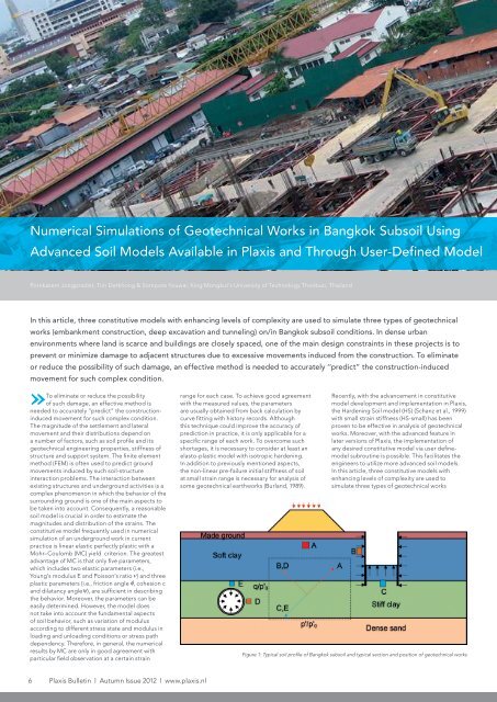
<strong>Numerical</strong> <strong>Simulations</strong> <strong>of</strong> <strong>Geotechnical</strong> <strong>Works</strong> <strong>in</strong> <strong>Bangkok</strong> Subsoil Us<strong>in</strong>gAdvanced Soil Models Available <strong>in</strong> <strong>Plaxis</strong> and Through User-Def<strong>in</strong>ed ModelPornkasem Jongpradist, Tr<strong>in</strong> Detkhong & Sompote Youwai, K<strong>in</strong>g Mongkut’s University <strong>of</strong> Technology Thonburi, ThailandIn this article, three constitutive models with enhanc<strong>in</strong>g levels <strong>of</strong> complexity are used to simulate three types <strong>of</strong> geotechnicalworks (embankment construction, deep excavation and tunnel<strong>in</strong>g) on/<strong>in</strong> <strong>Bangkok</strong> subsoil conditions. In dense urbanenvironments where land is scarce and build<strong>in</strong>gs are closely spaced, one <strong>of</strong> the ma<strong>in</strong> design constra<strong>in</strong>ts <strong>in</strong> these projects is toprevent or m<strong>in</strong>imize damage to adjacent structures due to excessive movements <strong>in</strong>duced from the construction. To elim<strong>in</strong>ateor reduce the possibility <strong>of</strong> such damage, an effective method is needed to accurately ‘‘predict” the construction-<strong>in</strong>ducedmovement for such complex condition.elim<strong>in</strong>ate or reduce the possibility»To<strong>of</strong> such damage, an effective method isneeded to accurately ‘‘predict” the construction<strong>in</strong>ducedmovement for such complex condition.The magnitude <strong>of</strong> the settlement and lateralmovement and their distributions depend ona number <strong>of</strong> factors, such as soil pr<strong>of</strong>ile and itsgeotechnical eng<strong>in</strong>eer<strong>in</strong>g properties, stiffness <strong>of</strong>structure and support system. The f<strong>in</strong>ite elementmethod (FEM) is <strong>of</strong>ten used to predict groundmovements <strong>in</strong>duced by such soil-structure<strong>in</strong>teraction problems. The <strong>in</strong>teraction betweenexist<strong>in</strong>g structures and underground activities is acomplex phenomenon <strong>in</strong> which the behavior <strong>of</strong> thesurround<strong>in</strong>g ground is one <strong>of</strong> the ma<strong>in</strong> aspects tobe taken <strong>in</strong>to account. Consequently, a reasonablesoil model is crucial <strong>in</strong> order to estimate themagnitudes and distribution <strong>of</strong> the stra<strong>in</strong>s. Theconstitutive model frequently used <strong>in</strong> numericalsimulation <strong>of</strong> an underground work <strong>in</strong> currentpractice is l<strong>in</strong>ear elastic perfectly plastic with aMohr–Coulomb (MC) yield criterion. The greatestadvantage <strong>of</strong> MC is that only five parameters,which <strong>in</strong>cludes two elastic parameters (i.e.,Young’s modulus E and Poisson’s ratio n) and threeplastic parameters (i.e., friction angle φ, cohesion cand dilatancy angle y),are sufficient <strong>in</strong> describ<strong>in</strong>gthe behavior. Moreover, the parameters can beeasily determ<strong>in</strong>ed. However, the model doesnot take <strong>in</strong>to account the fundamental aspects<strong>of</strong> soil behavior, such as variation <strong>of</strong> modulusaccord<strong>in</strong>g to different stress state and modulus <strong>in</strong>load<strong>in</strong>g and unload<strong>in</strong>g conditions or stress pathdependency. Therefore, <strong>in</strong> general, the numericalresults by MC are only <strong>in</strong> good agreement withparticular field observation at a certa<strong>in</strong> stra<strong>in</strong>range for each case. To achieve good agreementwith the measured values, the parametersare usually obta<strong>in</strong>ed from back calculation bycurve fitt<strong>in</strong>g with history records. Althoughthis technique could improve the accuracy <strong>of</strong>prediction <strong>in</strong> practice, it is only applicable for aspecific range <strong>of</strong> each work. To overcome suchshortages, it is necessary to consider at least anelasto-plastic model with isotropic harden<strong>in</strong>g.In addition to previously mentioned aspects,the non-l<strong>in</strong>ear pre-failure <strong>in</strong>itial stiffness <strong>of</strong> soilat small stra<strong>in</strong> range is necessary for analysis <strong>of</strong>some geotechnical earthworks (Burland, 1989).Recently, with the advancement <strong>in</strong> constitutivemodel development and implementation <strong>in</strong> <strong>Plaxis</strong>,the Harden<strong>in</strong>g Soil model (HS) (Schanz et al., 1999)with small stra<strong>in</strong> stiffness (HS-small) has beenproven to be effective <strong>in</strong> analysis <strong>of</strong> geotechnicalworks. Moreover, with the advanced feature <strong>in</strong>later versions <strong>of</strong> <strong>Plaxis</strong>, the implementation <strong>of</strong>any desired constitutive model via user def<strong>in</strong>emodelsubrout<strong>in</strong>e is possible. This facilitates theeng<strong>in</strong>eers to utilize more advanced soil models.In this article, three constitutive models withenhanc<strong>in</strong>g levels <strong>of</strong> complexity are used tosimulate three types <strong>of</strong> geotechnical worksFigure 1: Typical soil pr<strong>of</strong>ile <strong>of</strong> <strong>Bangkok</strong> subsoil and typical section and position <strong>of</strong> geotechnical works6 <strong>Plaxis</strong> Bullet<strong>in</strong> l Autumn Issue 2012 l www.plaxis.nl
γsatν ‘ φ ‘ c E’ ψR <strong>in</strong>terSoil parameter[kN/m3] [-] [°] [ kPa] [kPa] [°] [-]MC model 16 0.33 22 5 10000 0 1Table 1: Soil parameters <strong>of</strong> <strong>Bangkok</strong> s<strong>of</strong>t clay for MC modelE ref oedE ref 50 Eref urG ref 0γ 0.7m p refSoil parameter[kPa] [kPa] [kPa] [kPa] [-] [-] [kPa]HSsmall model 10000 10000 30000 22560 1x10⁻⁴ 1 100Table 2: Soil parameters <strong>of</strong> <strong>Bangkok</strong> s<strong>of</strong>t clay for HS-small modelBasic parameters [unit <strong>in</strong> parenthesis]N* [-] λ* [-] κ* [-] φ c[deg] r [-]1.85 0.17 0.043 24 0.2Intergranular stra<strong>in</strong> extension parametersm R[-] m T[-] R [-] β r[-] χ [-]5.25 5.25 0.0001 0.2 6Table 3: Soil parameters <strong>of</strong> <strong>Bangkok</strong> s<strong>of</strong>t clay for Mas<strong>in</strong>’s hypoplastic model for claySoil layer Weather Crust S<strong>of</strong>t Clay Medium Clay Stiff Clay Sandγ [kN/m3] 17 16 18 18 20satn [-] 0.32 0.33 0.33 0.33 0.3φ [°] 22 22 22 22 36c [kPa] 8 5 10 18 0E’ [kPa] 6000 5000 20000 60000 80000y [°] 0 0 0 0 0R <strong>in</strong>ter1 1 1 1 0.7Table 4: General MC soil model parameters for <strong>Bangkok</strong> subsoil (Wonglert et al., 2008)(embankment construction, deep excavationand tunnel<strong>in</strong>g) on/<strong>in</strong> <strong>Bangkok</strong> subsoil conditions.These <strong>in</strong>clude MC, HS-small and a hypoplastic(HP) model (Mas<strong>in</strong> 2005). The first two models areavailable <strong>in</strong> the <strong>Plaxis</strong> model library, whereas, thelast one was a user-def<strong>in</strong>ed model subrout<strong>in</strong>e.First, the calibration <strong>of</strong> selected models on thebasis <strong>of</strong> the extensive <strong>in</strong> situ test results for stiffclay and laboratory test results for s<strong>of</strong>t clay iscarried out. The analysis results are compared withtriaxial test results. Then analyses <strong>of</strong> three k<strong>in</strong>ds<strong>of</strong> geotechnical works are carried out with thosethree soil models with a s<strong>in</strong>gle set <strong>of</strong> parametersfor each model. The impact <strong>of</strong> select<strong>in</strong>g a soilmodel for geotechnical work analysis on accuracy<strong>of</strong> the predictions <strong>of</strong> soil displacements ishighlighted.Subsoil Condition and Soil Parameters<strong>Bangkok</strong> S<strong>of</strong>t Clay was deposited <strong>in</strong> mar<strong>in</strong>econditions at the delta <strong>of</strong> the rivers <strong>in</strong> the ChaoPhraya Pla<strong>in</strong>. The typical <strong>Bangkok</strong> subsoil isshown <strong>in</strong> Figure 1. It consists <strong>of</strong> made groundwith a thickness <strong>of</strong> 2.0 m over a 13.0 m thick s<strong>of</strong>tclay layer. The 12.0 m thick first stiff clay layer isencountered below the s<strong>of</strong>t clay layer at the depth<strong>of</strong> 15.0 m to 27.0 m Beneath the first stiff claylayer is the 8.0 m thick dense sand layer and the6.0 m thick second stiff clay layer at the depths<strong>of</strong> 35.0 m to 41.0 m respectively. The 19.0 m thicksecond dense sand layer at the depth <strong>of</strong> 60.0 m isunderneath these laters. The soil properties used<strong>in</strong> the analyses are ma<strong>in</strong>ly determ<strong>in</strong>ed from local<strong>in</strong>vestigated data correlation from comprehensive<strong>in</strong>-situ tests <strong>of</strong> previous mass transit projects (Prustet al., 2005) and previous laboratory tests (Shibuyaet al., 1997; Theramast, 1998 ; Uchaipichat, 1998).Note that the various soil models are appliedto the only s<strong>of</strong>t clay layer, whereas, other layersare assumed to behave as MC model <strong>in</strong> order tohighlight the <strong>in</strong>fluence <strong>of</strong> s<strong>of</strong>t clay model. Tables1-3 tabulate the soil parameters <strong>of</strong> s<strong>of</strong>t clay for MC,HS-small and HP model, respectively. The values<strong>of</strong> other soil layers are listed <strong>in</strong> Table 4. Figure1 also shows the typical section and position <strong>of</strong>geotechnical works on/<strong>in</strong> <strong>Bangkok</strong> subsoil.www.plaxis.nl l Autumn Issue 2012 l <strong>Plaxis</strong> Bullet<strong>in</strong> 7
<strong>Numerical</strong> <strong>Simulations</strong> <strong>of</strong> <strong>Geotechnical</strong> <strong>Works</strong> <strong>in</strong> <strong>Bangkok</strong> Subsoil Us<strong>in</strong>g Advanced Soil Models Available <strong>in</strong> <strong>Plaxis</strong> and Through User-Def<strong>in</strong>ed Model<strong>Numerical</strong> Analysis and ResultsAll problems which are from well-documentedcase histories hav<strong>in</strong>g reliable monitored data areanalyzed by PLAXIS 2D assum<strong>in</strong>g plane stra<strong>in</strong>condition with the appropriate analysis condition.These <strong>in</strong>clude the embankment construction(Bergado et al., 1994), deep excavation (Teparaksaet al., 1999) and tunnel<strong>in</strong>g (Suwansawat, 2002).The consolidation analysis is carried out forembankment construction s<strong>in</strong>ce the monitor<strong>in</strong>gdata was obta<strong>in</strong>ed at 300 days after construction.For analyses <strong>of</strong> deep excavation and tunnel<strong>in</strong>g,undra<strong>in</strong>ed conditions are assumed s<strong>in</strong>ce themeasured data were obta<strong>in</strong>ed dur<strong>in</strong>g and at afew days after construction. The extension <strong>of</strong> thef<strong>in</strong>ite mesh is wide enough and suitable boundaryconditions are assumed for all model boundariesto ensure the accuracy <strong>of</strong> the analysis.Embankment ConstructionFigure 2 depicts the f<strong>in</strong>ite element mesh,geometry and dimension <strong>of</strong> the problem for theembankment construction case. The case is theconstruction <strong>of</strong> 4.0 m high test embankment atAIT (Asian Institute <strong>of</strong> Technology) <strong>in</strong> 1992. Thedata to be compared is the settlement <strong>of</strong> theembankment measured at the level <strong>of</strong> the orig<strong>in</strong>alground us<strong>in</strong>g surface settlement plates for 300days after the construction.The comparison between measured data (reddot) and analysis results by three different soilmodels (color l<strong>in</strong>es) as embankment load<strong>in</strong>g<strong>in</strong>creases is illustrated <strong>in</strong> Figure 3. It is seen that,for this problem <strong>in</strong> which the soil behavior is ma<strong>in</strong>lygoverned by compression load<strong>in</strong>g, the resultsfrom HP are best comparable with measured data.While those <strong>of</strong> HS-small and MC have acceptableagreement with measured data <strong>in</strong> low to moderateload<strong>in</strong>g range.Deep ExcavationThe f<strong>in</strong>ite element mesh, geometry and dimension<strong>of</strong> the problem for underground construction <strong>of</strong><strong>Bangkok</strong> Metropolitan Hospital (BMH) which is a14 m deep excavation us<strong>in</strong>g 20 m high diaphragmwall as reta<strong>in</strong><strong>in</strong>g structure, is depicted <strong>in</strong> figure4. Figure 5 shows the comparison between theFEM analysis results and observed values <strong>of</strong> theexcavation works at the excavation depth <strong>of</strong> 2.0,5.7, and 11.0 m. For this problem which the soilbehaviors are ma<strong>in</strong>ly governed by compressionunload<strong>in</strong>g and extension unload<strong>in</strong>g paths, it showsthat the tendencies <strong>of</strong> analytical results with HPand HS-small models are satisfactory <strong>in</strong> terms <strong>of</strong>magnitude and the shape <strong>of</strong> the wall movementwhile those <strong>of</strong> MC model are over-estimated.Figure 6 shows the maximum lateral wallmovement from analyses compared with theobservation results <strong>of</strong> all cases (Oriflame Build<strong>in</strong>g,MRT Bang Sue, Ch<strong>in</strong>a tower and TPI Build<strong>in</strong>g). Itwas shown that the predicted results by HP andHS-small models give a satisfactory accuracy withthe observed data. Especially, when the maximumlateral wall movements are lower than 20.0 mm. Itcan be seen that, for the constitutive soil modelswhich take the small-stra<strong>in</strong> stiffness <strong>in</strong>to theaccount, the lateral wall movement is accuratelypredicted. However, the simple constitutive soilmodel such as elastic-perfectly plastic (MC) is stillable to accurately predict the lateral deformationonly for specific stra<strong>in</strong> range <strong>of</strong> each problem.Tunnel<strong>in</strong>gFor tunnel<strong>in</strong>g work, the ground surfacesettlements were measured by settlement marker.The case study is construction <strong>of</strong> the Mass RapidTransit (MRT) tunnel hav<strong>in</strong>g an <strong>in</strong>ner diameter <strong>of</strong>5.8 m at three sections <strong>in</strong>clud<strong>in</strong>g CS-8E, CS-8Cand CS-9A with the depth from ground surface at21.0, 19.0 and 17.0 m, respectively. As an example,the boundary condition and mesh <strong>of</strong> FEM analysisfor MRT tunnel at po<strong>in</strong>t CS-8E is shown <strong>in</strong> Figure7. The results <strong>of</strong> ground surface settlement areshown <strong>in</strong> Figure 8 for comparisons <strong>of</strong> the FEanalysis results and the observed values. It showsthat the analytical results from all models givesatisfactory tendencies <strong>in</strong> terms <strong>of</strong> the magnitudeand the shape <strong>of</strong> the settlement pr<strong>of</strong>ile. However,the results from HP are closed to measured valuesat near-centerl<strong>in</strong>e (0.0 - 18.0 m), whereas, those <strong>of</strong>MC are <strong>in</strong> good agreement with measured ones <strong>in</strong>the distance <strong>of</strong> 20.0 - 40.0 m from centerl<strong>in</strong>e.The results <strong>of</strong> surface settlement at the tunnelcenter (maximum), 5.5 and 11.0 m from the tunnelcenter are compared with measurement data atpo<strong>in</strong>t CS-8E, CS-8C and CS-9A as shown <strong>in</strong> Figure9. From FE analyses, HSsmall and HS model givea highly accurate prediction for a wide range <strong>of</strong>observed settlement. The results from MC modelseem to be more scattered.Figure 2: F<strong>in</strong>ite element mesh for embankment construction caseFigure 3: Comparison <strong>of</strong> settlement between measured data (red dot)and analysis results by three different soil models (color l<strong>in</strong>es)Figure 4: F<strong>in</strong>ite element mesh for deep excavation caseFigure 5: Comparison <strong>of</strong> wall movement <strong>of</strong> BMH construction betweenmeasured data and analysis results by three different soil models8 <strong>Plaxis</strong> Bullet<strong>in</strong> l Autumn Issue 2012 l www.plaxis.nl
<strong>Numerical</strong> <strong>Simulations</strong> <strong>of</strong> <strong>Geotechnical</strong> <strong>Works</strong> <strong>in</strong> <strong>Bangkok</strong> Subsoil Us<strong>in</strong>g Advanced Soil Models Available <strong>in</strong> <strong>Plaxis</strong> and Through User-Def<strong>in</strong>ed ModelDiscussionThe analyses <strong>of</strong> three k<strong>in</strong>ds <strong>of</strong> geotechnicalworks carried out <strong>in</strong> this article shows theimpact <strong>of</strong> soil model on the simulations. Us<strong>in</strong>gmore sophisticated soil models considerablyimproves the prediction <strong>of</strong> movements. The HPand HSsmall models which <strong>in</strong>clude non-l<strong>in</strong>earityat prefailure and high stiffness under very smallstra<strong>in</strong>, particularly the HP which has stress-pathdependent stiffness, give satisfactory accuracy <strong>of</strong>movement prediction for all three types <strong>of</strong> workcover<strong>in</strong>g the wide range <strong>of</strong> observed data. MCmodel over-predicts the deformation for analysis<strong>of</strong> embankment and excavation work, particularly,at range <strong>of</strong> small movement. However, theadvanced models are applied to only the s<strong>of</strong>t claylayer <strong>in</strong> this study. By apply<strong>in</strong>g to the other claylayers, the analysis results can be further improved(Rukdeechuai et al., 2009).References• Bergado, D.T., Long, P.V., Loke, K.H. and Werner,G. (1994), Performance <strong>of</strong> re<strong>in</strong>forced embankmenton s<strong>of</strong>t <strong>Bangkok</strong> clay with high strengthgeotextile re<strong>in</strong>forcement, Geotextiles andGeomembranes, Vol. 13(6-7), pp. 403-420.• Burland, J.B. (1989), N<strong>in</strong>th Laurits Bjerrum memoriallecture: Small is beautiful---The stiffness<strong>of</strong> soils at small stra<strong>in</strong>, Canadian <strong>Geotechnical</strong>Journal, Vol. 26(4), pp. 499-516.• Mas<strong>in</strong> D. (2005), A hypoplastic constitutivemodel for clay, International Journal for <strong>Numerical</strong>and Analytical Method <strong>in</strong> Geomechanics,Vol. 29, pp. 311-336.• Prust, R.E., Davies, J., and Hu, S. (2005), Pressuremeter<strong>in</strong>vestigate for mass rapid transit <strong>in</strong><strong>Bangkok</strong>-Thailand, Journal <strong>of</strong> the transportationresearch board, Transportation research <strong>of</strong>the national academies, Wash<strong>in</strong>gton D.C., No.1928, pp. 207 -217.• Rukdeechaui, T., Jongpradist, P., Wonglert, A.and Kaewsri, T.(2009), Influence <strong>of</strong> Soil Modelson <strong>Numerical</strong> Simulation <strong>of</strong> <strong>Geotechnical</strong> <strong>Works</strong><strong>in</strong> <strong>Bangkok</strong> Subsoil., EIT Research and DevelopmentJournal, Vol. 20(3), pp. 17-28.• Shibuya, S., Hanh, L.T., Wilailak K., Lohani T.N.,and Tanaka H. (1997), Characteriz<strong>in</strong>g stiffnessand strength <strong>of</strong> s<strong>of</strong>t <strong>Bangkok</strong> clay from <strong>in</strong>-situand laboratory tests, First Int. Conf. on SiteCharacteristics.• Teparaksa, W., Thasnanipan, N., Tanseng, P.(1999), Analysis <strong>of</strong> lateral wall movement fordeep excavation <strong>in</strong> <strong>Bangkok</strong> subsoils, Proceed<strong>in</strong>g<strong>of</strong> Civil and Environmental eng<strong>in</strong>eer<strong>in</strong>gconference “New Frontiers and Challenges”,<strong>Bangkok</strong>, pp. 67-76• Theramast N. (1998), Characteristic <strong>of</strong> pseudoelasticshear modulus and shear strength <strong>of</strong><strong>Bangkok</strong> clay, M. Eng. Thesis, AIT, Thailand.• Uchaipichat, A. (1998), Triaxial Tests on S<strong>of</strong>t<strong>Bangkok</strong> Clay with Different Applied StressPaths. M. Eng. Thesis, AIT, Thailand.• Schanz, T., Vermeer, P.A. and Bonnier, P.G. (1999)Formulation and verification <strong>of</strong> the Haren<strong>in</strong>g soilmodel, <strong>in</strong> Beyond 2000 <strong>in</strong> computational Geotechnics,A.A. Balkema, Roterdam, Netherlands,pp. 281-290• Suwanawat, S. (2002), Earth pressure balance(EPB) shield tunnel<strong>in</strong>g <strong>in</strong> <strong>Bangkok</strong> groundresponse and prediction <strong>of</strong> surface settlementsus<strong>in</strong>g artificial neural networks., PhD. Thesis,Massachusetts Institute <strong>of</strong> technology, Cambridge,USA.• Wonglert, A., Jongpradist, P., Kalas<strong>in</strong>, T.(2008),Wall Movement Analysis <strong>of</strong> Deep Excavation<strong>in</strong> <strong>Bangkok</strong> Subsoil consider<strong>in</strong>g Small Stra<strong>in</strong>Stiffness, Journal <strong>of</strong> Research <strong>in</strong> Eng<strong>in</strong>eer<strong>in</strong>gand Technology, Vol.5(4), pp. 393-405.Figure 6: Comparison between computed maximum wall displacementby different soil models and measured data <strong>of</strong> all case studiesFigure 7: FE mesh for tunnel<strong>in</strong>g caseFigure 8: Comparison <strong>of</strong> surface settlement at po<strong>in</strong>t CS-8E betweenmeasured data and analysis results by three different soil modelsFigure 9: Comparison between computed settlements by differentsoil models and measured data <strong>of</strong> all case studieswww.plaxis.nl l Autumn Issue 2012 l <strong>Plaxis</strong> Bullet<strong>in</strong> 9


