Vapour Phase Soldering System WAM 3000 Operating Instructions
Vapour Phase Soldering System WAM 3000 Operating Instructions
Vapour Phase Soldering System WAM 3000 Operating Instructions
- No tags were found...

Create successful ePaper yourself
Turn your PDF publications into a flip-book with our unique Google optimized e-Paper software.
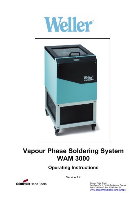
Page 1<strong>Vapour</strong> <strong>Phase</strong> <strong>Soldering</strong> <strong>System</strong><strong>WAM</strong> <strong>3000</strong><strong>Operating</strong> <strong>Instructions</strong>Version 1.2Cooper Tools GmbHCarl-Benz-Str. 2, 74354 Besigheim, GermanyTel: 07143/580-0; Fax 07143/580-108www.cooperhandtools.com/europe
Page 2Table of contents Page1. Prior to operation 31.1 Safety instructions 31.2 Transporting the soldering system within the factory 31.3 Description of vapour phase reflow soldering 41.4 Process description 41.5 The heat transfer medium 51.6 Description of the soldering system 7Technical data 82. Placing in operation 82.1 Prior to placing in operation 82.2 Filling the system with GALDEN 93. <strong>Operating</strong> the system 93.1 POWER button 113.2 START button 113.3 STOP button 123.4 UNLOCK button 133.5 Opening/closing GATE (when a process is not running) 133.6 Loading the workpiece carrier 133.7 External sensor / temperature measurement on circuit boards 143.8 PC interface 143.9 De-soldering system 143.10 Adjusting the process parameters 154. Error messages 165. Maintenance and inspection 176. Taking out of operation 177. Items supplied 178. Accessories / spare parts 17Cooper Tools GmbHCarl-Benz-Str. 2, 74354 Besigheim, GermanyTel: 07143/580-0; Fax 07143/580-108www.cooperhandtools.com/europe
Page 3We thank you for the confidence you have shown by purchasing the Weller <strong>WAM</strong> <strong>3000</strong><strong>Vapour</strong> <strong>Phase</strong> <strong>Soldering</strong> <strong>System</strong>. During manufacture the strictest quality requirementshave been applied; these assure the correct function of the device and make it possible toobtain optimal soldering results.Prior to placing the device in use, please read these operating instructions carefully.1. Prior to operation1.1 Safety instructionsTo ensure that the system is problem-free in use, the following safety rules should beobserved:Never operate the soldering system without process medium.Check the level of the GALDEN each time prior to placing in operation.The soldering system is only allowed to be operated by suitably instructed personnel.Under no circumstances reach into the hot soldering system. The vapour is invisibleand will cause very serious burns.Wear gloves for removing the item soldered. Avoid contact with parts inside thesystem.The workpiece carrier and the item soldered are still hot on removal from the system.Caution, there is a risk of burns.Malfunctions and faults on the system must be rectified without delay.Regularly check the soldering system for any damage.Maintenance work is only allowed to be performed by a trained and qualified specialist.Prior to maintenance work the soldering system is to be cooled down and isolated fromthe power supply.The manufacturer accepts no liability for usage beyond that described in the operatinginstructions or for unauthorised modifications.These operating instructions are to be read carefully and kept in the vicinity of thesoldering system in a place where they are clearly visible.The <strong>WAM</strong> <strong>3000</strong> soldering system complies with the EU declaration of conformity as perthe essential safety requirements in the directives 89/336/EEC, 73/23/EEC und89/392/EEC.1.2 Transporting the soldering system within the factoryThe soldering system is equipped as standard with castors (11) that enable it to be moved.The front castors can be locked. The system can thus be secured in the desired position.During transport within the factory, the system must not be tipped. The soldering systemmust be cold and there must be no liquid in the system. The system must not be subject toknocks or vibration during transport.Do not use the handle (26) on the lid for moving or carrying the unit. Only use the handle(26) for opening or closing the system.Cooper Tools GmbHCarl-Benz-Str. 2, 74354 Besigheim, GermanyTel: 07143/580-0; Fax 07143/580-108www.cooperhandtools.com/europe
Page 41.3 Description of vapour phase reflow solderingIn the vapour phase reflow soldering process, also called the condensation solderingprocess, an inert, electrically non-conductive liquid is heated to boiling temperature. Asaturated, chemically inert vapour phase forms above the liquid. The temperature of thevapour phase is identical to the boiling point of the process medium used. When anelectronic assembly is placed in the saturated vapour zone, vapour condenses on thesurface of the assembly until the surface is at the same temperature as the vapour. Thesoldering paste, which has a melting point below the temperature of the vapour, is thenalready molten.In this way it is possible for the user to obtain the best possible soldering result withoutmajor effort.The key advantages of condensation reflow soldering are:- Oxidation-free heating process in the inert vapour phase without the use of nitrogen.- Reproducible process conditions.- No overheating of the electronic assemblies- No shadowing and as a result absolutely even heating of the entire assembly.- The heating process is independent of the shape and colour of the item soldered. Thevapour produced creeps into the finest gaps. In this way even hidden components ore.g. BGAs are evenly heated in a defined manner.- Absolutely reproducible soldering profile even for different assemblies, as the heatingprocess is defined only by the physical laws relating to the vapour phase and themedium used.- No time consuming preparation of temperature profiles.- Environmentally friendly (no MAK figures)1.4 Process descriptionThe item to be soldered, once it is placed on the process zone, is brought to the reflowtemperature by homogenous and even condensation of vapour. A completely oxidationfreemelting process is achieved by heating the assembly with process vapour from thestart. The boiling temperature of the inert liquid defines the soldering temperature.<strong>Vapour</strong> production:In the soldering zone there is an inert liquid that is heated to its boiling temperature byelectrical heaters. Once the boiling point has been reached, the liquid does not becomeany hotter. All further energy added is used for the production of vapour (evaporationenthalpy). A saturated, chemically inert vapour zone forms with a temperature identical tothat of the liquid.The vapour condenses on the surface of the item to be soldered, as the temperature of theitem to be soldered is lower than the boiling temperature. The condensation process stopsas soon as the item to be soldered has reached the temperature of the vapour. Solderalloys with a melting temperature blow the temperature of the vapour are by then alreadymolten. The soldering process is complete after the cooling phase and the item soldered islifted out of the process chamber using the lift.Cooper Tools GmbHCarl-Benz-Str. 2, 74354 Besigheim, GermanyTel: 07143/580-0; Fax 07143/580-108www.cooperhandtools.com/europe
Page 5Principle of operation:Cold assemblyProduction of vapour is started- <strong>Vapour</strong> condenses and gives upheat to the assembly.- <strong>Vapour</strong> stops at the height of theassembly.- Assembly has reached vapourtemperature.- <strong>Vapour</strong> rises further.1.5 The heat transfer mediumTwo types with different boiling temperatures are available.- GALDEN TM HT200 (standard 200°C)- GALDEN TM HT230 (for lead-free solders 230°C)Weller uses high-boiling point perfluoropolyethers manufactured by AUSIMONT with thebrand name "GALDEN TM ".GALDEN TM perfluoropolyethers are liquid polymers of low molecular weight that compriseonly carbon (C), fluorine (F) and oxygen (O) atoms.The C-O and C-F bonds present in the molecules are extremely resilient. They are amongthe most stable bonds in organic chemistry. The fluorine atoms bonded to the centralpolymer chain perfectly shield the carbon structure and thus protect the delicate C-Cbonds against chemical and thermal attack.Cooper Tools GmbHCarl-Benz-Str. 2, 74354 Besigheim, GermanyTel: 07143/580-0; Fax 07143/580-108www.cooperhandtools.com/europe
Page 6Galden TM series:CF3 – O – CF – CF2 – O – CF – CF2 – O – CF – CF2 – O – CF – CF2 - ......... – O – CF3⏐ ⏐ ⏐ ⏐CF3 CF3 CF3 CF3The liquid polymers in the Galden TM series are constructed using this principle. They haveextraordinary properties:High temperature resistanceExcellent material compatibilityHigh resistance to reactive chemicalsGood dielectric propertiesLow vapour pressureNo flame pointHigh vapour densityExcellent coefficients of heat transferLow surface tension, good wetting propertiesNo hazardous materials in the context of work safetyNo chemical activity whatsoever (perfluorinated, i.e. no H or CI atoms)No risk of ozone damageGalden TM polymers are not inflammable or explosive and are extraordinarily inert to allchemicals up to high temperatures; they do not react with acids, alkalis or strong oxidisersand are compatible with all known plastics, metals and elastomers. When used correctly,i.e. boiled under normal pressure conditions, all Galden types are thermally stable.Due to the high density, the vapour phase forms an inert atmosphere and in this wayreliably protects the item to be soldered against oxidation. The oxygen present in themolecule is firmly bound chemically and does not react.Galden TM polymers have been tested in many trials, also under practical conditions, fortoxic by-products. These have never been found.Cooper Tools GmbHCarl-Benz-Str. 2, 74354 Besigheim, GermanyTel: 07143/580-0; Fax 07143/580-108www.cooperhandtools.com/europe
Page 71.6 Description of the soldering system261. Control panel 14. Sensor, level 12. External sensor 15. Sensor, level 23. Lid with viewing window 16. Sensor, level 34. Lid lock 17. Air outlet5. Workpiece carrier 18. Mains fuse6. Gate 19. Mains switch7. Heating sensor 20. Mains connection8. Heating 21. PC interface9. Fan 22. Connection for extraction system10. Cooling air fan 23. Transport lock11. Castors 24. Transport lock12. Medium 25. LCD display13. Medium sensor 26. Handle (only for opening and closing the lid)Cooper Tools GmbHCarl-Benz-Str. 2, 74354 Besigheim, GermanyTel: 07143/580-0; Fax 07143/580-108www.cooperhandtools.com/europe
Page 8Technical dataDimensions : (L x W x H) 615 x 490 x 950Mains voltage: 230 V/50 HzPower consumption : 2 kWMains fuse: 10 AWeight: 80 kgMax. format item soldered : (L x W x H) 300 x 300 x 55Max. weight item soldered : 1 kg2. Placing in operation2.1 Prior to placing in operationCompare the mains supply with the information on the rating plate. If the mains voltage iscorrect, connect the system to the mains (20). Switch on the system at the mains switch(19).=> "OFF" is indicated on the display and the "POWER" LED flashes.Press "POWER" button on the control panel (1). The device is in the ready mode. For anoverview and description of the function buttons, see 3. Control panel; page 10=> "POWER" LED illuminates.Press the "UNLOCK" button to unlock the lid (3) and then open the lid. The workpiececarrier (5) is in the top position. Remove transport lock.Important! Remove transport locks..1. Cut the cable tie (23) for fixing the workpiece carrier (5) and remove from thetank.2. The transport slide for the workpiece carrier (lift) is secured with a redclamping screw (24). Unscrew the clamping screw and remove from thetank.Close lid (3).Cooper Tools GmbHCarl-Benz-Str. 2, 74354 Besigheim, GermanyTel: 07143/580-0; Fax 07143/580-108www.cooperhandtools.com/europe
Page 92.2 Filling the system with GALDENThe system is in the ready mode. "OFF" is indicated on the display, the "POWER" LEDflashes, the lid is closed and the workpiece carrier is in the top position.Press "POWER" button. <strong>System</strong> is switched on.Press the menu button 2x until the command ***GATE*** appears on the display.Then keep the "UP" button ▲ pressed until the gate is opened. Then press the"UNLOCK" button 1x, open the lid (3) and remove the workpiece carrier (5).Fill 1kg GALDEN TM in the recess in the tank (medium reservoir) (12). The level sensor(13) in the recess in the tank must be covered with liquid. The top edge of the recess in thetank is the max. level.Refit the workpiece carrier and close the lid.3. <strong>Operating</strong> the systemSchematic layout:Workpiece carrier / LiftGateSensor Level 3Sensor Level 2Sensor Level 1MediumHeaterCooper Tools GmbHCarl-Benz-Str. 2, 74354 Besigheim, GermanyTel: 07143/580-0; Fax 07143/580-108www.cooperhandtools.com/europe
Page 10Control panelParameterUP / DOWNERRORLCD displayPOWER START STOPMENUUNLOCKLCD displayCommand indication,select menu usingbuttonsMenu:TEMPERATURESTANDBYSTOP LEVELGATECOOLER✷ ✷ ✷ T E M P E R A T U R E ✷ ✷ ✷ ✷H E A T E R 0 2 1 ° CR E A D YPosition in menu andheater controlHeater OFFHeater ONIndication of themenu parameterselected:HEATERLIQUIDLEVEL 1LEVEL 2LEVEL 3StateREADYSTANDBY HEAT UPSTANDBY READYTIMESignificanceThe unit is readyStandby heating up phaseThe unit is ready at the standbytemperatureIndication during the processwith time the process has beenrunning and process progressCooper Tools GmbHCarl-Benz-Str. 2, 74354 Besigheim, GermanyTel: 07143/580-0; Fax 07143/580-108www.cooperhandtools.com/europe
Page 113.1 POWER button:Switches on or off the <strong>WAM</strong> <strong>3000</strong>. When switched off, all operating modes are shut down,OFF is indicated on the display. The green LED above the POWER button flashes andindicates that the system is in ready mode.O F F<strong>System</strong> shutdown3.2 START button:<strong>Soldering</strong>/de-soldering process is started with the parameters set (see 3.10).Sequence: - Gate is opened- Lift moves down- Gate is closed- Heating up process: top of vapour rises tothe sensor level set- Cooling is switched on- Gate is opened- Lift moves up- Gate is closedProcess indication (example):EXTERNtemperatureindication menu✷ ✷ ✷ T E M P E R A T U R E ✷ ✷ ✷ ✷H E A T E R 0 2 1 ° CT I M E 0 1 7 5 sParameter HEATERHeater ONProzess stateElapsedprocess timeIndication ofthe heatertemperatureCooper Tools GmbHCarl-Benz-Str. 2, 74354 Besigheim, GermanyTel: 07143/580-0; Fax 07143/580-108www.cooperhandtools.com/europe
Page 12Possible error messages:1.L I F T N O T I N P O S I T I O NP R E S S S T O P B U T T O NF O R S T A R T P O S I T I O NThe lift is not in the start position (top limit switch). The lift can be moved tostart position using the Stop button.2.C A S I N G C O V E R O P E NThe lid must be closed. The process can only be started with thelid closed.3.3 STOP button:When the process is running, pressing the Stop button terminates the process and thesystem automatically returns to the start position (heater is shut down; gate is opened; liftmoves up; gate is closed).If the process is terminated by pressing the Power button, the lift and the gate can bemoved manually to the start position by keeping the Stop button pressed.Cooper Tools GmbHCarl-Benz-Str. 2, 74354 Besigheim, GermanyTel: 07143/580-0; Fax 07143/580-108www.cooperhandtools.com/europe
Page 133.4 UNLOCK button:Opens the lid.When the Unlock button is pressed, the lid is unlocked for 5 sec (green LED above theUnlock button is off). If the lid is left closed, it is locked again after 5 sec (green LED abovethe Unlock button is on).If the temperature of the medium is higher than 100°C the lid can only be openedif the gate is closed.T E M P E R A T U R E L O C K1 0 0 ° CG A T E M U S T B E C L O S E DIndication of the actualltemperature of the medium3.5 Opening/closing GATE (when a process is not running)The unit is in the ready mode with indication "OFF". The "POWER" LED is flashing andthe workpiece carrier is in the top position.Press "POWER" button. Using the buttons, select *** GATE ***. The gate can beopened or closed using the ▲ ▼button provided the temperature of the medium is below100°C.Alternative method of closing:Keep "STOP" button pressed. Gate closes.3.6 Loading the workpiece carrierWhen loading the workpiece carrier, it should be ensured that the stipulated maximum size(300 X 300 X 55) and weight for the item to be soldered (1kg) are not exceeded. The itemto be soldered must not protrude over the side or underneath the workpiece carrier.Attention: Wear gloves for removing the item soldered after the end of the process.The item soldered is still hot after the end of the process!!Cooper Tools GmbHCarl-Benz-Str. 2, 74354 Besigheim, GermanyTel: 07143/580-0; Fax 07143/580-108www.cooperhandtools.com/europe
Page 143.7 External sensor / temperature measurement on circuit boardsTo create a temperature profile, an appropriate measuring assembly is to be fitted with theexternal sensor. The connection for the external sensor (2) is in the process chamber. Thesensor must be correctly attached the assembly at a suitable point for it to work correctly.To obtain realistic measurements, SMD adhesive, thermally conductive silicone or Kaptonadhesive tape should be used for attaching the Ø 0.5mm sheathed thermocouple. Theindication of the temperature from the external sensor can be selected using the menubuttons and indicated on the display.3.8 PC interfaceThe system can be fully operated using separate software via the RS232 PC interface andthe sensor temperatures monitored and logged.3.9 De-soldering systemAn optional de-soldering system is available for the selective de-soldering of individualcomponents on the circuit board.The de-soldering system is heated in the system together with the assembly and thecomponents to be de-soldered. The de-soldering system comprises a lever system thatlifts the component to be de-soldered after the solder has melted.Cooper Tools GmbHCarl-Benz-Str. 2, 74354 Besigheim, GermanyTel: 07143/580-0; Fax 07143/580-108www.cooperhandtools.com/europe
Page 153.10 Adjusting the process parameters (only when the process is not running)▲ ▼ buttons:Selecting and changing the process parameters.Commands can be selected using the buttons.The parameters can be changed using the ▲ ▼ buttons.MenueSignificanceFunctions▲ ▼TEMPERATUREHEATERLIQUIDLEVEL 1LEVEL 2LEVEL 3EXTERNTemperature of the heater in °CTemperature of the medium in °CTemperature of the sensor, LEVEL 1 in °CTemperature of the sensor, LEVEL 2 in °CTemperature of the sensor, LEVEL 3 in °CTemperature of the external sensor in °CSTANDBYSwitch on the standby functionusing the ▲ ▼ buttonsWhen a standby function is active, the green LEDabove the START button flashes..OFFLIQUIDLEVEL 1LEVEL 2STOP LEVELThe process is stopped when this level is reached.Using the ▲ ▼ buttons adjustable between:Stop Level 1 is underneath the item soldered.Stop Level 2 is at approx. 25mm above height of itemsolderedStop Level 3 is at approx. 55mm above height of itemsolderedExternal sensor, can be positioned at any levelbetween Level 1 and 3..LEVEL 1LEVEL 2LEVEL 3EXTERNGATECOOLEROpen gate (as long as medium below 100°C)or close using the ▲ ▼ buttonsManual switch on and switch off of the cooling usingthe ▲ ▼. buttons. Manual cooling is also deactivatedby pressing the START and POWER buttons.OPENCLOSEONOFFCooper Tools GmbHCarl-Benz-Str. 2, 74354 Besigheim, GermanyTel: 07143/580-0; Fax 07143/580-108www.cooperhandtools.com/europe
Page 164. Error messagesError 1L I F T A N D G A T EN O T I N P O S I T I O NError 2Lift and gate not in position at limit switch. ) 1L I Q U I D E M P T YError 3Medium must be topped up.E E P R O M E R R O RError 4EEPROM no longer works correctly or settings have been lost. ) 1T I M E O U T O C C U R E DG A T E F A I L U R EError 5Gate control faulty. ) 1T I M E O U T O C C U R E DL I F T F A I L U R EError 6Lift control faulty. ) 1T I M E O U T O C C U R E DP R O C E S S T I M EError 7Permissible process time of 1800 sec has been exceeded.T E M P E R A T U R E E R R O RT H E R M O S W I T C HSwitch off unit and leave to cool down) 1 Please contact your Weller customer serviceCooper Tools GmbHCarl-Benz-Str. 2, 74354 Besigheim, GermanyTel: 07143/580-0; Fax 07143/580-108www.cooperhandtools.com/europe
Page 175. Maintenance and inspectionMonitoring the process mediumThe operator must monitor the level of the process medium. The level sensor (13) in therecess in the tank must always be covered with liquid. Check each time before placing inoperation.The process medium can be removed with the aid of the syringe supplied.Cleaning the tankThe process tank is made of stainless steel. The process chamber can be cleaned rapidlyand easily. Prior to cleaning, leave the system to cool down completely and remove theprocess medium. When the system is open it cannot be operated.Check the system for any damageRegularly check whether the moving parts function correctly and do not jam; also checkparts for damage.Attention: In general maintenance work is only to be performed by trained andauthorised personnel.6. Taking out of operationTo take the unit out of operation, switch off the unit at the mains switch (19) and unplugfrom the mains (20). The lid must be closed and there must not be any soldered items inthe system.7. Items supplied<strong>WAM</strong> <strong>3000</strong> <strong>Vapour</strong> phase soldering systemMains cable1 kg process medium GALDEN TM HT200<strong>Operating</strong> instructionsSyringeGloves8. Accessories / spare parts1 kg process medium GALDEN TM HT2005 kg process medium GALDEN TM HT2001 kg process medium GALDEN TM HT2305 kg process medium GALDEN TM HT230De-soldering systemExternal sensorSyringeGlovesCooper Tools GmbHCarl-Benz-Str. 2, 74354 Besigheim, GermanyTel: 07143/580-0; Fax 07143/580-108www.cooperhandtools.com/europe