54/852-1706W Instructions - AeroTech
54/852-1706W Instructions - AeroTech
54/852-1706W Instructions - AeroTech
- No tags were found...

Create successful ePaper yourself
Turn your PDF publications into a flip-book with our unique Google optimized e-Paper software.
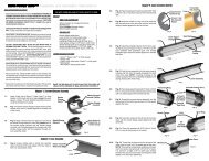
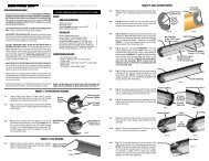
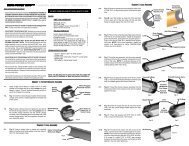
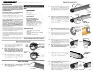
HIGH-POWER RMS-PLUS Assembly and Operation <strong>Instructions</strong>READ THIS BEFORE YOU BEGIN:• Study the illustrations and sequence of assembly.THE SEQUENCE OFASSEMBLY IS EXTREMELY IMPORTANT. READ ALL INSTRUCTIONSBEFORE USE. USE RMS MOTORS AND RELOAD KITS ONLY INACCORDANCE WITH ALL INSTRUCTIONS. Review the parts list andbecome familiar with all parts before assembly. IF ANY PARTS AREMISSING OR DAMAGED, CONTACT RCS AT 1-435-865-7100 OREMAIL AT warranty@aerotech-rocketry.com.• DO NOT USE ANY PARTS OF THE RMS SYSTEM THAT AREDAMAGED IN ANY WAY. If in doubt, contact RCS at the number abovefor assistance.• DO NOT MODIFY THE MOTOR IN ANY WAY. Modification of the motoror the reload kit parts could result in motor failure, lead to the destructionof both your rocket and motor and may cause personal injury, death and/or property damage. Modification of the motor or reload kit in any way willinvalidate your motor warranty.• USE ONLY AEROTECH RMS RELOAD KITS AND MOTOR PARTSTO REFURBISH YOUR RMS MOTOR. The <strong>AeroTech</strong>/RCS reload kitshave been designed specifically for use in your particular <strong>AeroTech</strong>/RCSRMS motor. Use of imitation components may destroy your motor,rocket and payload and will invalidate your motor warranty. Only use<strong>AeroTech</strong>/RCS RMS reload kits intended for your specific <strong>AeroTech</strong>/RCS RMS motor. DO NOT INTERCHANGE PARTS! Do not use<strong>AeroTech</strong>/RCS RMS reload kits or motor components for any otherpurpose than to refurbish an <strong>AeroTech</strong>/RCS RMS motor.• DO NOT REUSE ANY OF THE DISPOSABLE PARTS OF THE RMSRELOAD KIT. This includes the liner, nozzle and o-rings. Thesecomponents have been designed for one use only and must be discardedafter firing. Reuse can result in motor failure during subsequent operationand will invalidate your motor warranty.• Motors are hot after firing. Although the RMS operates at a lowertemperature than most disposable motors, the higher thermal conductivityof the aluminum motor parts may make it seem otherwise. If necessaryto handle a motor before it has cooled down, use a rag or similar article.• Read and follow the safety code of the Tripoli Rocketry Association (TRA)and comply with all federal, state and local laws in all activities involvinghigh power rockets.1-1. Apply a light coat of Synco Super Lube or othergrease to all threads and all 4 o-rings. This will facilitateassembly and prevents the threads from seizing.1-2. Fig.-1: Chamfer both inner edges of the delay insulatorwith your fingernail. Assemble the RMS-Plus delayelement, delay insulator, aft delay spacer and delay o-ring as shown. NOTE: It is not necessary to tape thedelay element or delay insulator, the hot gas seal isprovided by the delay o-ring alone.1-3. Fig.-2: Insert the forward delay spacer (1-1/8" O.D.neoprene washer) into the delay cavity until it is seatedagainst the forward end of the cavity. Apply a light filmof grease to the inner circumference of the delay cavity(but not the forward end of the cavity).1-4. Fig.-3: Insert the delay charge assembly shown in Fig.-1 into the delay cavity, o-ring end first, until it is seatedagainst the forward delay spacer. NOTES: When usinga plugged forward closure ONLY, fill the opening in theforward delay spacer with grease prior to installing thedelay charge assembly, and install the delay chargecomponents in this order: Forward delay spacer, delayo-ring, delay element, delay insulator and aft delay spacer.DO NOT OPEN RELOAD KIT UNTIL READY TO USE.PARTS:RMS HARDWARE<strong>54</strong>mm aft closure 1<strong>54</strong>/<strong>852</strong> Case (J275W) 1<strong>54</strong>/1280 Case (J415W) 1<strong>54</strong>/1706 Case (K550W) 1<strong>54</strong>mm forward closure (std. reg. length or plugged reg. length) 1RELOAD KITNozzle (black plastic part) 1Liner (2" O.D. black plastic tube) 1Propellant grains 2, 3 or 4Fwd & aft O-rings (1/8" thick X 2" O.D.) 2Liner O-ring (1/16" thick X 2" O.D.) 1Forward insulator (2" O.D. washer) 1Ejection charge cap (adhesive paper disk) 1RMS-Plus delay element (short solid part) 1Delay insulator (1-1/8" O.D. paper tube) 1Delay o-ring (1/8" thick X 1-1/8" O.D.) 1Aft delay spacer (short colored paper tube) 1Forward delay spacer (1-1/8" O.D. neoprene washer) 1ITEMS NEEDED FOR USE:Chapter 1. Forward Closure Assembly• Synco Super Lube or other grease• Hobby knife• FFFFG black powder• FirstFire or other igniter• Wet wipes or damp paper towelsSAVE THE RELOAD KIT PLASTIC BAG FOR THE USED RE-LOAD PARTS. DISPOSE OF BAG AND PARTS PROPERLY.DelayInsulator(Chamfered)Aft DelaySpacerForward DelaySpacer (1-1/8"O.D. Washer)DelayCavityApply Grease toThis SurfaceDelay ChargeAssembly InsertedCompletely Into<strong>54</strong>mm ForwardClosureFill with greasewhen usingplugged forwardclosure ONLYFig.-1DelayO-RingRMS-PlusDelay ElementFig.-2Fig.-3RMS<strong>54</strong>mmForwardClosureDelayO-RingForwardDelaySpacer2-1. Fig.-4: Place the greased liner (1/16" thick X 2" O.D.)o-ring over the large end of the nozzle insert until it restsagainst the nozzle flange.2-2. Fig.-4: Using a hobby knife or similar tool, remove theburr (rough, raised edge) from both inside ends of theliner tube. Insert the nozzle assembly into one end ofthe liner tube until the liner o-ring is seated against theliner.2-3. Fig.-5: Push the liner assembly, open end first, into themotor case until the nozzle protrudes from the caseabout 1/8". There will be some resistance as the liner o-ring passes into the motor case. NOTE: A light coat ofgrease on the outside surface of the liner will facilitateinstallation and casing cleanup after motor firing.2-4. Fig.-5: Place the greased aft (1/8" thick X 2" O.D.) o-ring into the groove in the nozzle insert.2-5. Fig.-6: Thread the aft (gold) closure into the motor caseby hand until about 1/16" gap remains between thecase and the closure. NOTE: Final tightening will bedone after the other motor components are loaded intothe case.2-6. Fig.-7: Install the propellant grains into the liner. NOTE:Only two grains are shown in some illustrations forsimplicity. RMS-<strong>54</strong>/<strong>852</strong> motors use two (2) grains,RMS-<strong>54</strong>/1280 motors use three (3) grains, and RMS-<strong>54</strong>/1706 motors use four (4) grains.2-7. Fig.-8: Place the forward insulator (2" O.D. washer)into the motor case until it is seated against the end ofthe liner.2-8. Fig.-8: Place the greased forward (1/8" thick X 2" O.D.)o-ring into the case, seated against the forward insulator.2-9. Fig.-9: With the motor case held in a horizontal position,thread the completed forward closure assemblyinto the open end of the motor case by hand until it isseated against the case.2-10. Finish tightening the aft (gold) closure by hand until it isseated against the case. NOTE: There will be someresistance to threading in the closure during the last 1/32" to 1/16" of travel. It is normal if a slight gap remainsbetween the closure and the case after tightening andthe grains rattle slightly inside the liner.3-1. Fig.-10: Thoroughly clean the outside of the motor ofany grease or other residue. Dispense enough ejectioncharge (FFFFG black powder) into the ejection chargewell of the forward closure to fill the well approximately3/4 full. NOTE: For 6" and larger diameter rockets, fillthe well completely.Chapter 2. Case AssemblyNozzle Flange Liner O-ringNozzleProtrudesabout 1/8"Aft O-ringAft Closure(1/16" Gap)Fig.-9EjectionChargeWellLinerLinerAssemblyChapter 3. Ejection Charge InstallationFig.-10LinerFig.-51/8" Forward O-RingCaseFig.-4CaseCase AssemblyPropellant GrainsFig.-7ForwardInsulatorFig.-8Fig.-6Case AssemblyAssembledForwardClosureEjection Charge(FFFFG Black Powder)
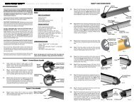
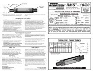
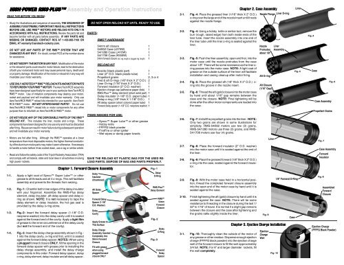
3-2. Fig.-11: Apply the ejection charge cap (adhesive paperdisk) to the center of the end of the forward closure. Withthe motor held in a NOZZLE DOWN position, gentlyshake the motor to settle the ejection charge into thecavity above the delay element.CenterNozzle Throat4-1. Fig.-12: Insert the coated end of a FirstFire, Firestaror other igniter through the center nozzle throat until itstops against the delay charge element.4-2. Secure the igniter to the nozzle with a piece of maskingtape.4-3. Install the motor into the rocket's motor mount tube.Ensure that the motor is securely retained in the rocketby using positive mechanical means to prevent it frombeing ejected during recovery system deployment.4-4. Prepare the rocket's recovery system and then launchthe rocket in accordance with the Tripoli RocketryAssociation (TRA) Safety Code and National Fire ProtectionAssociation (NFPA) Code 1127.Chapter 5. Post-Recovery CleanupNOTE: Perform motor clean-up as soon as possible after motorfiring. Propellant and delay charge residues become difficult toremove after 24 hours and can lead to corrosion of the metalparts. Place the spent motor components in the reload kit plasticbag and dispose of properly.5-1. After the motor has cooled down, unthread and removethe forward and aft closures.5-2. Remove the delay charge assembly components fromthe forward closure and discard. Using wet wipes ordamp paper towels, remove all delay charge and propellantresidue from the closures. WARNING: FAIL-URE TO COMPLETELY REMOVE DELAY CHARGERESIDUE FROM THE INSIDE OF THE FORWARDCLOSURE CAN LEAD TO GAS LEAKAGE ON ASUBSEQUENT FLIGHT AND DAMAGE TO YOURRMS MOTOR FORWARD CLOSURE AND ROCKETVEHICLE. NOTE: Use of a plugged forward closure willeliminate the possibility of this failure mode.5-3. Remove and discard the forward and aft o-rings fromthe motor case. Remove the liner, forward insulator,nozzle and liner o-ring from the casing by pushing onthe nozzle end and discard. Using wet wipes or damppaper towels, wipe the inside of the casing to remove allpropellant residue.5-4. Apply a light coat of grease to all threads and the inside of the motorcase. Reassemble metal parts and store motor in a dry place.<strong>AeroTech</strong> DivisionRCS Rocket Motor Components, Inc.Cedar City, UT 84720www.aerotech-rocketry.comChapter 3. Ejection Charge Installation (Cont'd)Install Igniter Against Delay ChargeFig.-12Fig.-11Chapter 4. Preparation For FlightChapter 6. First AidEjection Charge CapFor a minor burn, apply a burn ointment. For a severe burn,immerse the burned area in ice water at once and see aphysician as quickly as possible. In the unlikely event of oralingestion of the propellant, induce vomiting and see a physicianas quickly as possible. The <strong>AeroTech</strong>/RCS composite propellantconsists primarily of ammonium perchlorate and a rubberlikeplastic elastomer.Chapter 7. DisposalDamaged or defective reload kits should be returned to RCS.Chapter 8. Fire SafetyTests show that the pyrotechnic components of RMS reloadkits will not explode in fires and normally will not ignite unlesssubjected to direct flame and then will burn slowly. Use water tofight any fires in which <strong>AeroTech</strong> RMS reload kit pyrotechniccomponents may become involved: Direct the water at the Aero-Tech RMS reload kit pyrotechnic components to keep thembelow their 550 deg. F autoignition temperature. Foam and carbondioxide fire extinguishers will NOT extinguish burning propellantsof the type used in RMS reload kit pyrotechnic components.Keep reload kit pyrotechnic components away fromflames, sources of heat and flammable materials.Disclaimer and WarrantyNOTICE: As we cannot control the storage and use of ourproducts, once sold we cannot assume any responsibility forproduct storage, transportation or usage. RCS shall not be heldresponsible for any personal injury or property damage resultingfrom the handling, storage or use of our product. The buyerassumes all risks and liabilities therefrom and accepts and uses<strong>AeroTech</strong>/RCS products on these conditions. No warranty eitherexpressed or implied is made regarding <strong>AeroTech</strong>/RCSproducts, except for replacement or repair, at RCS's option, ofthose products which are proven to be defective in manufacturewithin one year from the date of original purchase. For repair orreplacement under this warranty, please contact RCS. Proof ofpurchase will be required. Note: Your state may provide additionalrights not covered by this warranty.P/N 20070 Rev. 3/30/10Made in U.S.A.©2005-2010 RCS Rocket Motor Components, Inc., All rights reserved200180160140120100806040200®HIGH-POWER RMSWithReloadable Motor SystemRMS PLUSTMRMS <strong>54</strong>/<strong>852</strong>-1706 WHITE LIGHTNINGThrust in PoundsDivision of RCS Rocket Motor Components, Inc.Typical Time-Thrust Curves:Certified By The National Association of Rocketry and the Tripoli Rocketry AssociationK550WJ415WDO NOT OPENRELOAD KITUNTIL READYTO USE0.00 0.50 1.00 1.50 2.00 2.50 3.00 3.50 4.00THIS PACKAGE CONTAINS ONE RMS-PLUS RELOAD KIT:J275W-L (<strong>54</strong>/<strong>852</strong>) J415W-L (<strong>54</strong>/1280)TMAdvanced DelaySealing SystemJ275WTime in SecondsNOTE: RMS-<strong>54</strong>/<strong>852</strong>-1706 reload kits do not include ejection charge. Use FFFFG black powder.K550W-L (<strong>54</strong>/1706)NOTE: This reload kit is sold in a "long" delay configuration ONLY. For other delays, use one of theappropriate <strong>AeroTech</strong>/RCS Reload Delay Kits (RDK's) for the delay time desired. Please refer to theRDK cross-reference list on back of the reload kit header card for proper RDK selection.W = White Lightning Short = approx. 6 sec, Medium = approx. 10 sec., Long = approx. 14 sec., Extra-Long = approx. 18 sec.The reload kits shown above are ONLY for use in <strong>AeroTech</strong>/RCS RMS-<strong>54</strong> High-Power motors.RMS-<strong>54</strong>/<strong>852</strong>-1706 WHITE LIGHTNING RELOAD KIT DATAH ardware Desig. P erformance Desig.T otal Impulse (Max.)P ropellant Wt.Loaded Motor Wt.RMS-<strong>54</strong>/<strong>852</strong>RMS-<strong>54</strong>/1280RMS-<strong>54</strong>/1706J275WJ415WK550W850N-sec440g (0.969 lb)883 g (1.94 lb)1280N-sec660g (1.45 lb)1199 g (2.64 lb)1700N-sec880g (1.94 lb)1515 g (3.34 lb)RMS-<strong>54</strong>/<strong>852</strong>-1706 HARDWARE DATAHardwareDesignationMotorDiameterMotorLengthHardwareWeightReload UsedR MS-<strong>54</strong>/<strong>852</strong>2 .125" (<strong>54</strong>mm)9 .49"278g (0.612 lb)J275WR MS-<strong>54</strong>/12802 .125" (<strong>54</strong>mm)12.82"338g (0.744 lb)J415WR MS-<strong>54</strong>/17062 .125" (<strong>54</strong>mm)16.15"399g (0.879 lb)K550WNOTE: Total impulse shown is optimum. Motor lengths are measured from end of aft closure to end of forward closure.NOTE: SALE TO PERSONS UNDER 18 YEARS OF AGE PROHIBITED BY FEDERALLAW. WARNING-FLAMMABLE: Read <strong>Instructions</strong> Before Use. KEEP OUTOF REACH OF CHILDREN. FOR USE ONLY BY CERTIFIED HIGH-POWER USERS18 YEARS OF AGE OR OLDER. DO NOT SMOKE when loading these motors or usein the vicinity of open flames.TM