F3Dn Service Manual Parts Replacement / Section 2.2 ... - FFSNorge
F3Dn Service Manual Parts Replacement / Section 2.2 ... - FFSNorge
F3Dn Service Manual Parts Replacement / Section 2.2 ... - FFSNorge
- No tags were found...

You also want an ePaper? Increase the reach of your titles
YUMPU automatically turns print PDFs into web optimized ePapers that Google loves.
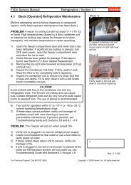
<strong>F3Dn</strong> <strong>Service</strong> <strong>Manual</strong> <strong>Parts</strong> <strong>Replacement</strong> / <strong>Section</strong> 2.32.3 Automation Assembly <strong>Replacement</strong>[Part No. 18000567]1) Roll the unit out to allow access to rear service panel.2) Disconnect power at outlet. [Pull plug.]3) Remove two screws securing service panel.4) Disconnect motor harness power connections from boththe Basket [Present] and Door Lift Motors.5) Disconnect both Basket [Present] and Door OpenSensor leads at the Main Control Board.6) Remove the Hoppers from the refrigerationcompartment, the stainless steel loading chutes andplastic freezer bottom, to expose the product dispensingdoors.7) Remove [and save] the spring retaining clip from the leftside Door Rotation Block Pin. [Slip round loop over pinthen remove.] Release tension on the spring and allow itto hang from the right side spring mounting screw.8) Rotate doors down to expose the shaft mounting screwson both doors.9) Using a 1/8” [3 mm] Allen/hex wrench, remove the threescrews that attach each door to its pivot shaft.10) Slide the Door Frame off the left door shaft.11) Remove the rubber seal and hole cover from both DoorShafts.12) Using a 7/16” [11 mm] box wrench or socket/wrenchremove the four Automation Assembly mounting boltsfrom the side mounting channels.13) Carefully remove the complete Automation Assembly,including door shafts, from the unit.14) Install new Automation Assembly [P/N 18000567].Replace and tighten the mounting bolts using your 7/16”[11 mm] wrench. [Tip: Don’t fully tighten. Some mountingadjustment may be required. See <strong>Section</strong> 3.1]15) Reinstall hole covers, gaskets, door frame and doors ondoor shafts. [Tip: See other Lane to verify assembly.]16) Install freezer bottom for next adjustment.17) Adjust Door Lift Assembly by minimal tightening of 7/16”[11 mm] bolts and then manually positioning the Door LiftAssembly front-to-back, so that the door frame iscentered in the rectangular opening of freezer bottom.18) With dispense doors in CLOSED position, adjust heightof Door Lift Assembly so that dispense doors just “kiss”the freezer bottom to form a seal. [Note: Care should betaken to keep dispense doors level and centered inrectangular opening.] [MORE…See 2.4 Continued][Photo 1]Disconnect power leads fromboth motors.[Photo 2]Disconnect sensor leads at theMain Control Board.[Photo 3]Open load doors from the frontand remove three shaftmountingscrews on each.[Photo 4]Remove the four AutomationAssembly mounting bolts.For Technical Support, Call 800-537-2653.Copyright Ó 2005 Franke, Inc. All rights reserved.