F3Dn Service Manual Parts Replacement / Section 2.2 ... - FFSNorge
F3Dn Service Manual Parts Replacement / Section 2.2 ... - FFSNorge
F3Dn Service Manual Parts Replacement / Section 2.2 ... - FFSNorge
- No tags were found...

Create successful ePaper yourself
Turn your PDF publications into a flip-book with our unique Google optimized e-Paper software.
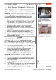
<strong>F3Dn</strong> <strong>Service</strong> <strong>Manual</strong> <strong>Parts</strong> <strong>Replacement</strong> / <strong>Section</strong> 2.142.14 Touch Pad Controls <strong>Replacement</strong>[Part No. 19000798]1) Disconnect power at outlet. [Pull plug.]2) If needed, position a stepladder or stable work platformto access the top of the <strong>F3Dn</strong> Control Panel.3) Using a medium Phillips screwdriver, remove the two topcontrol panel mounting screws.4) Carefully tilt back the black control panel to expose theunit control wiring ribbons, cable harnesses and green &yellow ground wire.5) Disconnect the two control ribbon harnesses, the Power-ON switch and Temperature Display wiring connectorsand ground wire lead, to separate the control panel fromunit. NOTE: Do not allow control panel to hang fromwiring and/or ribbon harness.6) Move Control Panel to a convenient, level work surface.7) Using the 3/8” [10 mm] nut driver, remover the sixbacking plate mounting nuts from the Lane OperatorPanel Display that requires replacement.8) Remove the backing plate and then the old touch pad.9) Position the replacement Operator Touch PanelAssembly [P/N 19000798] in the opening of the frontcontrol panel frame.10) Replace the backing plate and secure using the sixmounting nuts just removed.11) Return the control panel assembly to the unit andreattach the two ribbon harnesses, Power-ON andTemperature Display wiring connectors and ground wireconnection. CAUTION: Make sure ground is attached.12) Put Control Panel Assembly back in mounting positionand secure with the two Phillips screws removed earlier.13) Plug in unit power cord to power supply.Test the new Lane Touch Pad Controls Assembly by:14) Filling the Lane Hopper with Fries to a level past the LowProduct Sensor.15) Switch ON main power switch on the front control panel.16) Press and turn on LANE POWER at the front controlpanel. NOTE: Make sure Lane is in AUTO Mode.17) When LOAD READY light comes ON, test operation ofLOAD SIZE touch pad by cycling through: LARGE,SMALL, MEDIUM and LARGE settings.18) Insert empty fry basket into loading position. If fries areproperly dispensed, the Lane Touch Pad Controls arefunctioning properly.19) Return <strong>F3Dn</strong> Dispenser to normal operating location.[Photo 1]Lane Operator Panel Controls[Photo 2]Remove the two top front panelmounting screws to access theTouch Pad Control Assemblies.[Photo 3]Disconnect both lane ribbonharness connections, PowerSwitch & Temperature Displayterminal connections and groundlead to completely separatecontrol panel from dispenser.‣Rev. 2 10/06For Technical Support, Call 800-537-2653.Copyright Ó 2006 Franke, Inc. All rights reserved.