F3Dn Service Manual Parts Replacement / Section 2.2 ... - FFSNorge
F3Dn Service Manual Parts Replacement / Section 2.2 ... - FFSNorge
F3Dn Service Manual Parts Replacement / Section 2.2 ... - FFSNorge
- No tags were found...

You also want an ePaper? Increase the reach of your titles
YUMPU automatically turns print PDFs into web optimized ePapers that Google loves.
<strong>F3Dn</strong> <strong>Service</strong> <strong>Manual</strong> <strong>Parts</strong> <strong>Replacement</strong> / <strong>Section</strong> 2.32.3 Automation Assembly <strong>Replacement</strong>[Part No. 18000567]1) Roll the unit out to allow access to rear service panel.2) Disconnect power at outlet. [Pull plug.]3) Remove two screws securing service panel.4) Disconnect motor harness power connections from boththe Basket [Present] and Door Lift Motors.5) Disconnect both Basket [Present] and Door OpenSensor leads at the Main Control Board.6) Remove the Hoppers from the refrigerationcompartment, the stainless steel loading chutes andplastic freezer bottom, to expose the product dispensingdoors.7) Remove [and save] the spring retaining clip from the leftside Door Rotation Block Pin. [Slip round loop over pinthen remove.] Release tension on the spring and allow itto hang from the right side spring mounting screw.8) Rotate doors down to expose the shaft mounting screwson both doors.9) Using a 1/8” [3 mm] Allen/hex wrench, remove the threescrews that attach each door to its pivot shaft.10) Slide the Door Frame off the left door shaft.11) Remove the rubber seal and hole cover from both DoorShafts.12) Using a 7/16” [11 mm] box wrench or socket/wrenchremove the four Automation Assembly mounting boltsfrom the side mounting channels.13) Carefully remove the complete Automation Assembly,including door shafts, from the unit.14) Install new Automation Assembly [P/N 18000567].Replace and tighten the mounting bolts using your 7/16”[11 mm] wrench. [Tip: Don’t fully tighten. Some mountingadjustment may be required. See <strong>Section</strong> 3.1]15) Reinstall hole covers, gaskets, door frame and doors ondoor shafts. [Tip: See other Lane to verify assembly.]16) Install freezer bottom for next adjustment.17) Adjust Door Lift Assembly by minimal tightening of 7/16”[11 mm] bolts and then manually positioning the Door LiftAssembly front-to-back, so that the door frame iscentered in the rectangular opening of freezer bottom.18) With dispense doors in CLOSED position, adjust heightof Door Lift Assembly so that dispense doors just “kiss”the freezer bottom to form a seal. [Note: Care should betaken to keep dispense doors level and centered inrectangular opening.] [MORE…See 2.4 Continued][Photo 1]Disconnect power leads fromboth motors.[Photo 2]Disconnect sensor leads at theMain Control Board.[Photo 3]Open load doors from the frontand remove three shaftmountingscrews on each.[Photo 4]Remove the four AutomationAssembly mounting bolts.For Technical Support, Call 800-537-2653.Copyright Ó 2005 Franke, Inc. All rights reserved.
<strong>F3Dn</strong> <strong>Service</strong> <strong>Manual</strong> <strong>Parts</strong> <strong>Replacement</strong> / <strong>Section</strong> 2.3Rev. 1 6/062.3 Automation Assembly <strong>Replacement</strong>Continued: [Part No. 18000567]19) Tighten all 7/16” [11 mm] bolts securely and recheckdispense door-to-bottom “kiss” seal for uniform fit.20) Reattach power service wires to both motors [Red =positive, black = negative] and sensor leads to MainControl Board. [See other Lane to verify connections.]21) Plug in unit power cord to power supply.@Tools Required:‣ 3/8” [10 mm] flat bladescrew driver‣ 1/8” [3 mm] AllenWrench‣ 7/16” [11 mm] box orsocket wrench22) Test Automation Assembly operation by:23) Turning on main power switch & pressing LANE-POWERtouch pad on control overlay.24) If LOAD READY light is on, position empty fry basketunder hopper to activate fry loading cycle, if lane is inAUTO mode. If in MANUAL mode, press the MANUALDISPENSE touch pad.25) If Lane dispenses fries, it is working properly.26) Close rear service access panel and return <strong>F3Dn</strong>Disperser to normal operating location.For Technical Support, Call 800-537-2653.Copyright Ó 2005 Franke, Inc. All rights reserved.
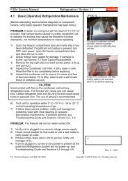
<strong>F3Dn</strong> <strong>Service</strong> <strong>Manual</strong> <strong>Parts</strong> <strong>Replacement</strong> / <strong>Section</strong> 2.42.4 Door Lift Slide <strong>Replacement</strong>[Part No. 18000673]1) Roll the unit out to allow access to rear service panel.2) Disconnect power at outlet. [Pull power cord plug.]3) Remove two screws securing service access panel.4) Detach the Black and Red electric power connectionsfrom the Slide Lift and Door [Open] Motors.5) Remove [and save] the spring retaining clip from the leftside Door Rotation Block Pin. Slip round loop over pinthen remove. Release tension on spring and allow it tohang from the right side spring mounting screw.6) Remove the spring retaining clip from the right side ofthe white plastic Door Cam Link. Remove that link andthe two small plastic shaft spacers.7) From the front side rotate product doors down to exposethe shaft mounting screws on both doors.8) Using a 1/8” [3 mm] Allen/hex wrench, remove the threescrews that attach each door to its pivot shaft.9) Slide the Door Frame off the left door shaft.10) Remove the rubber seal cover from both Door Shafts.11) Using the 5/32” [4 mm] Allen/hex wrench, remove thefour Door [Open] Motor mounting screws. Removing thetwo top screws will separate the Door Open Sensor &Bracket from the motor assembly. It can hang down fromcable.12) Using the 5/32” [4 mm] Allen/hex wrench, remove thefour Door Lift Motor mounting screws. [This is the bottommotor.]13) Carefully remove the motor and gearbox assembly fromthe machined aluminum Door Slide Lift Assembly.14) Remove the Door Lift Shaft from the Slide BearingAssembly.15) Using a ¼” [6 mm] box wrench or socket, remove thefour Door Lift Slide mounting bolts.16) Pull Door Lift Slide sub-assembly [with shafts] out ofcabinet and place on a convenient work surface.17) Using a ’C’ ring pliers, remove both retaining rings on thefreezer side of each door mounting shaft. [Back retainingring on each shaft should stay in place.]18) Using a rubber mallet, tap door shafts out of Door LiftSlide bearings.19) Take the replacement Door Lift Slide and use yourrubber mallet to tap door shafts back into place.20) Replace the two ‘C’ Rings on each shaft.21) Reposition the sub-assembly back though the cabinetpenetrations.[Photo 1]Remove the spring clip retainerfrom left side door rotation blockpin, then relieve spring tension.[Photo 2]Remove the two upper motormounting screws first.[Photo 3]Open load doors from the frontand remove three shaftmountingscrews on each.‣.For Technical Support, Call 800-537-2653.Copyright Ó 2006 Franke, Inc. All rights reserved.
<strong>F3Dn</strong> <strong>Service</strong> <strong>Manual</strong> <strong>Parts</strong> <strong>Replacement</strong> / <strong>Section</strong> 2.42.4 Door Lift Slide <strong>Replacement</strong>CONTINUED [Part No. 18000673][Photo 4]22) Align the assembly and reinstall the four mounting bolts.23) Reinstall hole covers, gaskets, door frame and doors ondoor shafts. [Tip: See other Lane to verify assembly.]24) Install Door [Open] Motor assembly starting with the twobottom mounting screws. Remount Door Open Sensor &bracket using the two upper motor mount screws.25) Reconnect the two motor electric power connections:[Red = positive; Black = negative].26) Replace white plastic Door Cam Link, with Stop Screw tothe right side. [Note: Make sure bushings and spacersare on both left and right cam pins, before replacing link.27) Attach the spring retainer clip to right side Door RotationBlock pin.28) Using both hands, extend spring eye to left side DoorRotation Block Pin. [CAUTION: Spring will be undertension and may snap back.] Plastic bushings must beinstalled in spring end loops, before mounting the spring.29) Replace spring retaining clip and lock in place over pin.30) Reposition the Door Lift Shaft in the Slide bearingAssembly.31) Reinstall the Door Lift Motor Assembly [P/N 19000161].Make sure the gear box output shaft fits into the slot inthe lift cam.32) Replace and tighten the four motor mounting screwsusing your 5/32” [4 mm] Allen wrench.33) IMPORTANT - Check the gap or calibration of the loadcell [weighs basket contents] under the motor byinserting a .020” [.50 mm] feeler or gap gauge betweenset post on left [open] side of load cell. [See Photo 6]34) If load cell gap is larger or smaller than .020”/.50 mm,adjust gap set nut located below left side of load cell.35) Attach power service wires to Door Lift Motor. [Red =positive, Black = negative]Test the replacement Door Slide Lift as follows:36) Plug in unit power cord to 120-volt power supply.37) Turn on main power switch & pressing LANE-POWERtouch pad on front control overlay.38) If LOAD READY light is on, position empty fry basketunder Hopper to activate fry loading cycle. [AUTO Mode]39) If Lane properly dispenses fries, the AutomationAssembly is working properly.40) Close rear service access panel and return F3DDispenser to normal operating location.Remove the four motor mountingscrews from the Door Lift Motor.[Photo 5]Ensure motor drive aligns withthe slot in the slide plate counterbore.[Photo 6]After replacing this motor, checkthe gap on the load cell using a.020 [.50 mm] feeler or gapgauge.Rev. 1 9/06For Technical Support, Call 800-537-2653.Copyright Ó 2006 Franke, Inc. All rights reserved.
<strong>F3Dn</strong> <strong>Service</strong> <strong>Manual</strong> Motor Test / <strong>Section</strong> 2.52.5 Motor Test ProcedureNote: Follow this Motor Test Procedure before replacing:• Drum Rotor Motor [<strong>Section</strong> 2.6]• Door Lift Motor [<strong>Section</strong> 2.7]• Door [Open] Motor [<strong>Section</strong> 2.81) Roll the unit out to allow easy access to rearservice panel.2) Leave unit plugged in but be cautions whenopening unit back and touching Boards, etc.3) Remove the two screws to open rear serviceaccess panel.4) Go to Main Control Boards and locate thediagnostic display (upper right) and threewhite command buttons marked: SW1, SW2and SW3, just below the display surfacemount.Key: Bold type = Actual Display Content. // = Break to second line of DisplayStep Action Required Resulting Diagnostic Display1 From unit front turn Lane Power TouchPad ON.Display will cycle through setup screensending with: Stby [Standby].2 Push and hold buttons: SW1 and SW3: All Clear?? // 1=OK 3=Exit3 Press SW1 button. [=OK] U.S. or Alt?? // 1=US 2= Alt. [Alternate]4 Press SW1 or SW2 button as required.[Procedure assumes SW1=US pressed.]Preload = 2175 [Four digit number]Add Large Load [681 gm or 1.5 lbs.] //1=OKNote: Check to verify fries loading chute is in place and no stray fries are in loading area.5 Press SW1 button. [=OK]6 Add 1.5 pound weight [or six 4:1 Patties] tolane product loading chute.7 Press SW1 button. [=Cal] Large = 226 // Z = ---- P= ---- C=---- //Done 1= Cal 3 = Exit8 Press S3 button. [to exit Calibration Test]9 Press and hold S2 and S3 buttons Motor Test ? // 1=OK 2= Nxt 3=Exit10 Press SW1 button. [=OK] Drum Mtr? // 1= OK 3=Nxt [Next]11 Press SW1 button. [=OK] Drum Trq = 0000 [Torque value] // 1 =Run 3 = Next12 Press SW1 button to run motor. Checkmotor shaft and listen for excessive noise.Drum Trk = 00XX [Numeric value willchange. A high number means a problem.]13 Press SW3 button [=Next Test]. Lift Motor? // 1 = OK 3 = Next14 Press SW1 button. [=OK] Trq = 0000 LC = 0000 [Load Cell] //1 = Run 3 = Next15 Press SW1 button. [Lowers slide, turnscam & motor rotates.]Trq = 00XX [Typically small value] LC =XXXX [Live reading from Load Cell. Cancheck load cell function.]For Technical Support, Call 800-537-2653.Copyright Ó 2006 Franke, Inc. All rights reserved.
<strong>F3Dn</strong> <strong>Service</strong> <strong>Manual</strong> Motor Test / <strong>Section</strong> 2.52.5 Motor Test Procedure Continued:Step Action Required Resulting Diagnostic Display16 Press SW3 button. [Go to next test.] Door Motor? // 1 = OK 3 = Nxt [Next]17 Press SW1 button. [=OK] Door Trq = 0000 // 1 = Go 3 = Ex [Exit]18 Press SW1 button. [Activates one full Door Trq = 00XX [Typically a low value] //door-open & dispense cycle.]1 = Go 3 = Ex XXX [Cycle count]19 Press SW3 button [=Next]. Error Log ? 1 = OK 2 = Nxt 3 = Ext20 Press SW1 button. [=OK] FTO=000 [Fill Time Out – the number ofoccurrences] DTQ=000 [Drum torquefaults – number of occurrences] // 2 = Clr3 = Rtn [Return]21 Press SW3 button [=Clear] Resets FTO and DTQ counters to “000”22 Press SW3 button [=Rtn] Show Cal ? // 1 = OK 2 = Nxt 3 = Ext23 Press SW1 button [=OK] Z = 00000 C= 00024 P = 02145 // 1 = OK3 = Ext [Values should be close to thoseon sticker. See photo below.]24 Press SW3 button [=OK] Motor Tests ? 1 = OK 2 = Nxt 3 = Ext25 Press SW3 button [=Exit] Shut Lift /Stby [Standby]Specific base-level Diagnostic Values are logged at Plant andposted on back of unit above Main Control Boards.‣ To Replace Drum Rotor Motor…See <strong>Section</strong> 2.6‣ To Replace Door Lift Motor…See <strong>Section</strong> 2.7‣ To Replace Door [Open] Motor…See <strong>Section</strong> 2.8‣Rev. 2 10/06For Technical Support, Call 800-537-2653.Copyright Ó 2006 Franke, Inc. All rights reserved.
<strong>F3Dn</strong> <strong>Service</strong> <strong>Manual</strong> <strong>Parts</strong> <strong>Replacement</strong> / <strong>Section</strong> 2.62.6 Drum Rotor Motor <strong>Replacement</strong>[Part No. 19000161]1) Roll unit out to allow access to rear service panel.2) Disconnect power at outlet. [Pull power cord plug.]3) Remove two screws securing service access panel.4) Disconnect both motor harness power connections.5) Using a 5/32” [4 mm] Allen Wrench, remove the fourmotor mounting screws.6) Remove motor by pulling straight out. Motor Rotor Blockwill remain in place.7) Install new Drum Rotor Motor [P/N 19000161]. Ensuremotor gear case drive shaft engages rectangular slot inplastic Rotor Drive Shaft.8) Replace and tighten the four motor mounting screwsusing your 5/32” [4 mm] Allen Wrench.9) Reattach power leads to motor: [Red = positive, Black =negative]10) Reconnect unit to power supply.11) Test for proper motor operation by:12) Turning ON main power switch & pressing LANE-POWER touch pad on control overlay.13) If LOAD READY light is on, position empty fry basketunder hopper to activate loading cycle in AUTO Mode. InMANUAL Mode press MANUAL DISPENSE touch pad.14) If Fry Hopper is empty, place screwdriver or knife bladein front of load sensor to trick the dispenser.15) Position an empty fry basket in the fill chute.16) If lane dispenses fries [if present] or if rotors turnsmoothly in an attempt to dispense fries, the motor isworking properly.[Photo 1]Disconnect motor powerleads.[Photo 2]Remove the four motormounting screws.17) Close rear service access panel and return <strong>F3Dn</strong>Dispenser to normal operating location.@Tools Required:‣ 3/8” [10 mm] flat bladescrew driver‣ 5/32” [4 mm] AllenWrenchRev. 1 9/06For Technical Support, Call 800-537-2653.Copyright Ó 2006 Franke, Inc. All rights reserved.
<strong>F3Dn</strong> <strong>Service</strong> <strong>Manual</strong> <strong>Parts</strong> <strong>Replacement</strong> / <strong>Section</strong> 2.72.7 Door Lift Motor <strong>Replacement</strong>[Part No. 19000161]1) Roll the unit out to allow access to rear service panel.2) Disconnect power at outlet. [Pull power cord plug.]3) Remove two screws securing service access panel.4) Disconnect motor harness power connections from the[lower] Door Lift Motor.5) Using a 5/32” [4 mm] Allen/hex wrench, remove the fourmotor mounting screws. [They are all the same length.]6) Carefully remove the motor and gearbox assembly fromthe machined aluminum Slide Bearing Assembly.7) Install the new Door Lift Motor Assembly [P/N19000161]. Make sure the gear box output shaft fits intothe slot in the lift cam.8) Replace and tighten the four mounting screws using your5/32” [4 mm] Allen wrench.9) IMPORTANT - Check the gap or calibration of the loadcell [weighs basket contents] under the motor byinserting a .020” [.50 mm] feeler or gap gauge betweenset post on left [open] side of load cell. [See Photo 3]10) If load cell gap is larger or smaller than .020” [.50 mm],carefully adjust gap set nut located below left side of loadcell.11) Attach power service wires to new Door Lift Motor. [Red= positive, Black = negative]12) Plug in unit power cord to power supply.[Photo 1]Disconnect power leads from[lower] Door Lift Motor.[Photo 2]Remove the four motor mountingscrews.[Photo 3]Test the replacement Door Lift Motor as follows:13) Turn on main power switch & pressing LANE-POWERtouch pad on control overlay.14) If LOAD READY light is on, position empty fry basketunder hopper to activate fry loading cycle in AUTOMode. In MANUAL Mode press MANUAL DISPENSEtouch pad.15) If Lane properly dispenses fries, it is working properly.16) Close rear service access panel and return <strong>F3Dn</strong>Dispenser to normal operating location.‣After replacing motor, check thegap on the load cell using a.020”/.50 mm feeler or gapgauge.Rev. 1 9/06For Technical Support, Call 800-537-2653.Copyright Ó 2006 Franke, Inc. All rights reserved.
<strong>F3Dn</strong> <strong>Service</strong> <strong>Manual</strong> <strong>Parts</strong> <strong>Replacement</strong> / <strong>Section</strong> 2.82.8 Door [Open] Motor <strong>Replacement</strong>[Part No. 18000558]1) Roll the unit out to allow access to rear service panel.2) Disconnect power at outlet. [Pull power cord plug.]3) Remove two screws securing service access panel.4) Remove [and save] the spring retaining clip from the leftside Door Rotation Block Pin. Slip round loop over pinthen remove. Release tension on spring and allow it tohang from the right side spring mounting screw.5) Remove the spring retaining clip from the right side ofthe white plastic Door Cam Link. Remove that link. [Youdon’t need to remove the small plastic shaft spacers.]6) Using the 5/32” [4 mm] Allen/hex wrench, remove thefour motor mounting screws, beginning with the two TOPscrews.7) Removing the longer top screws will separate the DoorOpen Sensor & Bracket from the motor assembly.8) Detach the two motor electric power connections.9) Install new motor assembly [P/N 18000558] starting withthe two bottom mounting screws.10) Remount Door Open Sensor & bracket using the twoupper motor mount screws.11) Reconnect the two motor electric power connections:[Red = positive; Black = negative].12) Replace white plastic Door Cam Link, with Stop Screw tothe right side. [Note: Make sure bushings and spacersare on both left and right cam pins, before replacing link.]13) Attach the spring retainer clip to right side Door RotationBlock pin.14) Using both hands, extend spring eye to left side DoorRotation Block Pin. [CAUTION: Spring will be undertension and may snap back.] Plastic bushings must beinstalled in spring end loops, before mounting the spring.15) Replace spring retaining clip and lock in place over pin.Test the replacement Door [Open] Motor as follows:16) Plug in unit power cord to power outlet.17) Turn on main power switch & pressing LANE-POWERtouch pad on front control overlay.18) If LOAD READY light is on, position empty fry basketunder Hopper to activate fry loading cycle in AUTOMode. In MANUAL Mode press MANUAL DISPENSE.19) If Lane properly dispenses fries, replacement Motor anddispensing assembly is working properly.20) Close rear service access panel and return <strong>F3Dn</strong>Dispenser to normal operating location.[Photo 1]Remove the spring clip retainerfrom left side door rotation blockpin, then relieve spring tension.[Photo 2]Remove the two upper motormounting screws first.[Photo 3]Ensure motor drive aligns withthe slot in the slide plate counterbore.‣Rev. 1 9/06For Technical Support, Call 800-537-2653.Copyright Ó 2006 Franke, Inc. All rights reserved.
<strong>F3Dn</strong> <strong>Service</strong> <strong>Manual</strong> <strong>Parts</strong> <strong>Replacement</strong> / <strong>Section</strong> 2.92.9 Load Cell <strong>Replacement</strong> [Part No. 19000165]1) Roll the unit out to allow access to rear service panel.2) Disconnect power at outlet. [Pull power cord plug.]3) Remove two screws securing service access panel.4) Disconnect Load Cell cable lead at Main Control Board.[See Photo 1]5) Carefully open split in plastic wire harness sheath to freecable all the way down to Load Cell.6) Using a 3/16” [5 mm] Allen/hex wrench, remove the twoLoad Cell bracket screws and remove assembly.7) Using a 5 mm Allen/hex wrench separate the Load Cellfrom its Mounting Bracket by removing the two right-sidescrews.8) Re-attach the new Load Cell to the old Bracket with themounting screws just removed. IMPORTANT – whenmounted on assembly, there must be clearance betweenback of load cell and assembly mounting plate.9) Remount the Load Cell Assembly and tighten the twomounting screws using your 3/16” [5 mm] Allen wrench.10) IMPORTANT – After installation, check the gap of theload cell [weighs basket contents] by inserting a .020”[.50 mm] feeler or gap gauge between set post on left[open] side of load cell. [See Photo 4]11) If load cell gap is larger or smaller than .020”, carefullyadjust gap set nut located below left side of load cell.12) Reroute Load Cell cable lead back up to the MainControl Board and re-attach terminal.13) Re-route and bundle cable in flexible plastic harnesssheath. Use plastic ties, if needed.14) Plug in unit power cord to power supply.15) Test the replacement of the Load Cell as follows:16) Turn on main power switch & pressing LANE-POWERtouch pad on control overlay.17) If LOAD READY light is on, position empty fry basketunder hopper to activate fry loading cycle in AUTOMode. In MANUAL Mode press MANUAL DISPENSE.18) If Lane properly dispenses fries, it is working properly.19) [NOTE: It may be necessary to recalibrate load cell usingprocedure provided with replacement unit.20) Close rear service access panel and return <strong>F3Dn</strong>Dispenser to normal operating location.[Photo 1]Disconnect Load Cell cableconnector at Main ControlBoard.[Photo 2]Remove the two Load CellBracket mounting screws.[Photo 3]Separate Load Cell from themounting bracket by removingscrew on right side of assembly.[Photo 4]After replacing Load CellAssembly, check the gap on theload cell using a .020 [.50 mm]feeler or gap gauge.Rev. 1 9/06For Technical Support, Call 800-537-2653.Copyright Ó 2006 Franke, Inc. All rights reserved.
<strong>F3Dn</strong> <strong>Service</strong> <strong>Manual</strong> <strong>Parts</strong> <strong>Replacement</strong> / <strong>Section</strong> 2.102.10 Door-Closing Spring & Bushing<strong>Replacement</strong> [Part No. 19001676]1) Roll the unit out to allow access to rear service panel.2) Disconnect power at outlet. [Pull power cord plug.]3) Remove two screws securing service access panel.4) Locate broken or weak/extended Door-Closing Spring.5) Remove [and save] the spring retaining clip from the leftside Door Rotation Block Pin. Slip round loop over pinthen remove.6) Remove and discard partial, extended or broken spring.7) Using a 1/8” [3 mm] Allen wrench, remove the right sidespring mounting screw and discard remainder of spring.8) Install the new Door Spring with plastic bushings in endloops [P/N 19001676] by replacing right side retainingscrew and tightening with 1/8” [3 mm] Allen wrench.9) Using both hands, extend spring eye to left side DoorRotation Block Pin. [CAUTION: Spring will be undertension and may snap back.]10) Replace spring retaining clip and lock in place over pin.Test the replacement Door-Closing Spring as follows:11) Remove Fry Hopper and Loading Chute from Lane.12) <strong>Manual</strong>ly rotate product doors against spring tension.Ensure both doors open in unison and 90 degrees downto full open.13) Reassemble loading chute and fry hopper, then close thefreezer door.14) Plug in unit power cord to power supply.15) Turn on main power switch & pressing LANE-POWERtouch pad on operator panel.16) If LOAD READY light is on, position empty fry basketunder Hopper to activate fry loading cycle in AUTOMode. In MANUAL Mode press MANUAL DISPENSEtouch pad.17) If Lane properly dispenses fries, replacement spring isworking properly.18) Close rear service access panel and return <strong>F3Dn</strong>Dispenser to normal operating location.[Photo 1]By hand remove the spring clipretainer from left side doorrotation block pin.[Photo 2]Use a 1/8” Allen Wrench toremove and later tighten rightside spring retaining screw.[Photo 3]Test new spring by manuallyopening product doors againstspring tension. Both doorsshould rotate down againstresistance of the extensionspring.‣Rev. 1 9/06For Technical Support, Call 800-537-2653.Copyright Ó 2006 Franke, Inc. All rights reserved.
<strong>F3Dn</strong> <strong>Service</strong> <strong>Manual</strong> <strong>Parts</strong> <strong>Replacement</strong> / <strong>Section</strong> 2.112.11 Low Product Sensor <strong>Replacement</strong>[Part No. 19000384]1) Roll the unit out to allow access to rear service panel.2) Disconnect power at outlet. [Pull power cord plug.]3) Remove two screws securing service access panel.4) Disconnect Low Product Sensor cable lead at MainControl Board. [See Photo 1]5) Use a ‘C’ Ring pliers to remove the external ‘C’ Ringretainer from the Low Product Sensor Sleeve.6) Remove the retaining washer with its formed fingerretainer.7) The Low Product Sensor slides out of the outer sleevebut must be unscrewed counterclockwise to break thesoft sealant (on front of the sensor) from outer sleeve.8) Take new Low Product Sensor [P/N 19000384] andapply a small amount of silicone sealant to the nose thenslide it back into the plastic sensor sleeve.9) Replace the retaining washer over the sensor sleeve,being careful to insert the retaining finger into thereceiving slot on the sleeve.10) Re-insert the external ‘C’ Ring.11) Reattach the Low Product sensor cable lead to the MainControl Board terminal.12) Plug in unit power cord to power supply.13) Adjust Low Product Sensor Sensitivity by:14) Position an empty hopper in the freezer compartment.15) Locate the small red plastic LED indicator light on theMain Control Board. [It is labeled: Low Product]16) Open the small plastic cover on the back of the sensorwith your fingertips or the small plastic screwdriver.17) Using the a small plastic screwdriver provided, slowlyturn the adjustment screw on the sensor clockwise untilthe LED light comes ON, then back that screwcounterclockwise until the LED light just goes OFF.[Photo 1]Disconnect Low Product Sensorcable connector at Main ControlBoard.[Photo 2]Remove the inner ’C’ Ringretainer and screw out thesensor.[Photo 3]After removing the small plasticplug, use the plastic 1/16”screwdriver provided to adjustsensor sensitivity.18) Test the Low Product Sensor by:19) Fill the Lane Hopper with fries to a level above the LowProduct Sensor. Switch ON main power on front panel.Press and turn ON Lane at front Control Panel. If LOWPRODUCT light comes on, repeat Sensor sensitivityadjustment described in Step 15.20) If this sensor adjustment corrects problem, replace smallplastic plug in back of Low Product Sensor. NOTE: thisplug must me closed to avoid water getting in sensor.21) Close rear service access panel and return <strong>F3Dn</strong>Dispenser to normal operating location.For Technical Support, Call 800-537-2653.‣Rev. 1 9/06Copyright Ó 2006 Franke, Inc. All rights reserved.
<strong>F3Dn</strong> <strong>Service</strong> <strong>Manual</strong> <strong>Parts</strong> <strong>Replacement</strong> / <strong>Section</strong> 2.122.12 Basket-Present Sensor <strong>Replacement</strong>[Part No. 19000182]1) Roll the unit out to allow access to rear service panel.2) Disconnect power at outlet. [Pull power cord plug.]3) Remove two screws securing service access panel.4) Locate Basket-Present Sensor cable lead connection toMain Control Board. [See Photo 1]5) Disconnect Basket Present Sensor cable where it matesto main wiring harness, just above Door Open Assembly.[See Photo 2]6) Using a crescent wrench or 1” [25 mm] box wrench,unscrew the sensor-retaining nut from the Basket-Present Sensor Sleeve. [See Photo 3]7) The Basket-Present Sensor must be unscrewedcounterclockwise from the mounting block. [The plasticthreads are very fine, so this will take some time.]8) Take the new Basket-Present Sensor [P/N 19000182]and screw [clockwise] back into plastic sensor sleeve,until fully seated.9) Replace the sensor-retaining nut and tighten securelywith wrench, but do NOT over-tighten.10) Reattach the Basket-Present Sensor cable lead to theMain Wiring Harness. [See Photo 2]11) Plug in unit power cord to power supply.[Photo 1]Disconnect Basket Load Sensorcable connector at Main ControlBoard.[Photo 2]The Basket-Present Sensor’scable can be disconnected fromthe main wiring harness.[Photo 3]Test the new Basket-Present Sensor by:12) Filling the Lane Hopper with Fries to a level past the LowProduct Sensor. Switch ON main power on front panel.Press LANE POWER and turn on Lane at the frontControl Panel. NOTE: Make sure Lane is in AUTO Mode.13) When LOAD READY light comes ON, insert empty frybasket into loading position. If fries are dispensed,Basket-Present Sensor is functioning properly.14) NOTE: A green indicator on the back of the sensorcomes on when it senses the basket.15) Close rear service access panel and return <strong>F3Dn</strong>Dispenser to normal operating location.Remove sensor-retaining nutwith wrench and screw out thebasket sensor.‣Rev. 1 12/06For Technical Support, Call 800-537-2653.Copyright Ó 2006 Franke, Inc. All rights reserved.
<strong>F3Dn</strong> <strong>Service</strong> <strong>Manual</strong> <strong>Parts</strong> <strong>Replacement</strong> / <strong>Section</strong> 2.132.13 Door-Open Sensor <strong>Replacement</strong>[Part No. 19000192]1) Roll the unit out to allow access to rear service panel.2) Disconnect power at outlet. [Pull plug.]3) Using the medium Phillips screwdriver, remove twoscrews securing service access panel.4) Disconnect Door-Open Sensor cable lead from the wiringharness.5) Using the 5/32” [4 mm] Allen/hex wrench, remove the toptwo [Door Open] motor mounting screws only.6) Remove the Door Open Sensor & Bracket from themotor assembly. Slide the sensor bracket to the right,clearing the sensor flag or fin. Unscrew sensor mountingscrews to remove sensor from the bracket.7) Position new Door Open Sensor [P/N 19000192] on themounting bracket and attach using the two screws justremoved.8) Position new sensor and bracket over motor mountingholes. Ensure actuating flag is spaced midway withinsensor slot.9) Replace and tighten the two upper motor mountingscrews using the 5/32” [4 mm] Allen/hex wrench.10) Reattach the new Door Open Sensor cable lead to themotor wiring harness.[Photo 1]The Door Open Sensor &Bracket is mounted with theupper [Basket Lift] motormounting screws.[Photo 2]Use 5/32” Allen/hex wrench toremove and tighten mountingscrews.Test the replacement Door-Open Sensor as follows:11) Plug in unit power cord to power supply.12) Turn on main power switch & pressing LANE POWERtouch pad on front control panel. NOTE: Make sure Laneis in AUTO Mode.13) If LOAD READY light is on, position empty fry basketunder Hopper to activate fry loading cycle.14) If Lane properly dispenses fries, replacement Door-OpenSensor and dispensing assembly is working properly.15) Close rear service access panel and return <strong>F3Dn</strong>Dispenser to normal operating location.‣Rev. 2 10/06For Technical Support, Call 800-537-2653.Copyright Ó 2005 Franke, Inc. All rights reserved.
<strong>F3Dn</strong> <strong>Service</strong> <strong>Manual</strong> <strong>Parts</strong> <strong>Replacement</strong> / <strong>Section</strong> 2.142.14 Touch Pad Controls <strong>Replacement</strong>[Part No. 19000798]1) Disconnect power at outlet. [Pull plug.]2) If needed, position a stepladder or stable work platformto access the top of the <strong>F3Dn</strong> Control Panel.3) Using a medium Phillips screwdriver, remove the two topcontrol panel mounting screws.4) Carefully tilt back the black control panel to expose theunit control wiring ribbons, cable harnesses and green &yellow ground wire.5) Disconnect the two control ribbon harnesses, the Power-ON switch and Temperature Display wiring connectorsand ground wire lead, to separate the control panel fromunit. NOTE: Do not allow control panel to hang fromwiring and/or ribbon harness.6) Move Control Panel to a convenient, level work surface.7) Using the 3/8” [10 mm] nut driver, remover the sixbacking plate mounting nuts from the Lane OperatorPanel Display that requires replacement.8) Remove the backing plate and then the old touch pad.9) Position the replacement Operator Touch PanelAssembly [P/N 19000798] in the opening of the frontcontrol panel frame.10) Replace the backing plate and secure using the sixmounting nuts just removed.11) Return the control panel assembly to the unit andreattach the two ribbon harnesses, Power-ON andTemperature Display wiring connectors and ground wireconnection. CAUTION: Make sure ground is attached.12) Put Control Panel Assembly back in mounting positionand secure with the two Phillips screws removed earlier.13) Plug in unit power cord to power supply.Test the new Lane Touch Pad Controls Assembly by:14) Filling the Lane Hopper with Fries to a level past the LowProduct Sensor.15) Switch ON main power switch on the front control panel.16) Press and turn on LANE POWER at the front controlpanel. NOTE: Make sure Lane is in AUTO Mode.17) When LOAD READY light comes ON, test operation ofLOAD SIZE touch pad by cycling through: LARGE,SMALL, MEDIUM and LARGE settings.18) Insert empty fry basket into loading position. If fries areproperly dispensed, the Lane Touch Pad Controls arefunctioning properly.19) Return <strong>F3Dn</strong> Dispenser to normal operating location.[Photo 1]Lane Operator Panel Controls[Photo 2]Remove the two top front panelmounting screws to access theTouch Pad Control Assemblies.[Photo 3]Disconnect both lane ribbonharness connections, PowerSwitch & Temperature Displayterminal connections and groundlead to completely separatecontrol panel from dispenser.‣Rev. 2 10/06For Technical Support, Call 800-537-2653.Copyright Ó 2006 Franke, Inc. All rights reserved.
<strong>F3Dn</strong> <strong>Service</strong> <strong>Manual</strong> <strong>Parts</strong> <strong>Replacement</strong> / <strong>Section</strong> 2.152.15 Main Power ON/OFF Switch <strong>Replacement</strong>[120V/60Hz use Part No. 3126151][230V/50Hz use Part No. RH110-C2L]1) Disconnect power at outlet. [Pull plug.]2) If needed, position a stepladder or stable work platformto access the top of the <strong>F3Dn</strong> Control Panel.3) Using a medium Phillips screwdriver, remove the two topcontrol panel mounting screws.4) Carefully tilt forward the black control panel coverassembly. It can remain attached to the control wiringribbon and cable wiring harnesses, but support theweight with one hand or get help to hold it.5) Note wire numbers and mounting sequence on back ofpower switch. Remove the three terminal connectionsfrom the Power ON/OFF Switch.6) From the back carefully depress the plastic locking tabson either side of the switch and push the switch outthrough the panel front.7) Take the new Power ON/OFF Switch [120V/60Hz = P/N:3126151; 230/V/50Hz = RH110-C2L] and push it throughthe front panel opening until the side tabs lock it in place.Switch bezel should be flush with the front panel.8) Reconnect the three switch wires. When viewed fromback of switch, the wires are connected:‣ 120V/60Hz: T1 = Brown, T2 (center) = Black (L1), T3= White (Neutral)‣ 230V/50Hz; T1 = Brown, T2 (center) = Brown, T3 =Blue (Neutral)9) Return the control panel assembly to the mountingposition and install the two mounting screws.10) Plug in unit power cord to power supply.[Photo 1]Remove the two top panelmounting screws to access thefront control assemblies.(120V/60Hz model shown)[Photo 2]Remove the three switchterminal leads, depress plasticlocking tabs and push out thePower ON/OFF switch throughpanel front.Test the new Power ON/OFF Switch by:11) Switch on Main Power Switch at the front control panel.Integrated [red] pilot light should come on and youshould hear the compressor come on, after a shortdelay.12) Press the LANE POWER touch pad for both Lanes. Ifboth Lane [MANUAL] lights come on, the Main PowerSwitch is functioning properly.13) Return <strong>F3Dn</strong> Dispenser to normal operating location, if itwas moved.Rev. 2 12/06For Technical Support, Call 800-537-2653.Copyright Ó 2005 Franke, Inc. All rights reserved.
<strong>F3Dn</strong> <strong>Service</strong> <strong>Manual</strong> <strong>Parts</strong> <strong>Replacement</strong> / <strong>Section</strong> 2.162.16 LED Unit Temperature Display <strong>Replacement</strong>[Part No. 19000437]1) Disconnect power at outlet. [Pull plug.]2) If needed, position a stepladder or stable work platformto access the top of the <strong>F3Dn</strong> Control Panel.3) Remove the two top control panel mounting screws.4) Carefully remove the black control panel coverassembly. It can remain attached to the unit with controlwiring ribbon and cable wiring harnesses, but support itwith ladder or get help to hold it. NOTE: Do not letcontrol panel dangle from ribbon and cable harnesses.5) Disconnect the display cable connector [routed from thetemperature controller located inside electric chase] fromback of the remote display.6) From the back of the control panel, carefully release thetwo locking hairpin clips on either side of the LEDDisplay module using a small flat blade screwdriver andpull it through cutout in the front of the panel.7) Take the new LED Temperature Display [P/N: 19000437]and insert it into the front panel. From back of the displaydepress and insert locking tabs to secure remote display.8) Reconnect the display sensor connector to display.9) Return the front control panel assembly to the mountingposition and install the two mounting screws.10) Plug in unit power cord to power supply.[Photo 1]Remove the two top front panelmounting screws to access thefront control assemblies.[Photo 2]Disconnect display harnessconnector from display. Removeright & left plastic retainers andpush LED Display out throughpanel front.Test the new LED Temperature Display by:11) Switch on Main Power Switch at the front control panel.12) The temperature display should show the current freezercompartment temperature and track the pull-down to asafe operating temperature range of 0 to -10° F [-18 to -23° C].NOTE: If new remote temperature display doesn’t fix theproblem, see <strong>Section</strong> 4.2 [Thermostat <strong>Replacement</strong>] forfurther options.13) If new Temperature Display functions normally, return<strong>F3Dn</strong> Dispenser to normal operating location, if it wasmoved.Rev. 2 10/06For Technical Support, Call 800-537-2653.Copyright Ó 2006 Franke, Inc. All rights reserved.
<strong>F3Dn</strong> <strong>Service</strong> <strong>Manual</strong> <strong>Parts</strong> <strong>Replacement</strong> / <strong>Section</strong> 2.16A2.16A Freezer Temperature Controller - SensorCable <strong>Replacement</strong> [Part No. 19000648]1) Disconnect power at outlet. [Pull plug.]2) If needed, position a stepladder or stable work platformto access the top of the <strong>F3Dn</strong> Control Panel.3) Remove the two top control panel mounting screws andfour screws securing the sloped access panel. NOTE:Do not let control panel dangle from its ribbon and cableharnesses.4) The Danfoss Thermostat is mounted inside an electricchase and has a control with attached sensor cable.Remove the four screws holding the chase cover inplace to reveal the thermostat. [If necessary, remove thepress fit knob and then the hex nut holding thethermostat to the electric chase.]5) Disconnect the sensor cable from the temperaturecontroller.6) Pull unit out to access rear service panels.7) Open back service access panel and identify sensorcable penetration point into the freezer compartment. It isjust above the main PC boards.8) Remove the soft putty sealant and gently pull faultysensor cable through hole toward back of unit. NOTE: Ifresistance is encountered, it may be necessary to loosenor remove four mounting hex bolts securing CenterHopper Support Bracket inside freezer, to allow sensorbulb to pass through. Use a 13 mm Allen/Hex wrench.9) Clip any cable ties holding sensor cable in place andremove the cable and sensor.10) Install new sensor cable bulb through freezer wall andensure it is correctly positioned inside the protective boxattached to the Hopper Center Support Bracket.11) Tighten four hex bolts for the center support finger tight,being careful not to pinch the sensor cable.12) Replace insulating putty around freezer compartmentpenetration.13) Route sensor cable up the back of the unit, into theelectric chase and plug connector end into Danfosstemperature control.14) If temperature control was removed, remount it to electricchase and tighten hex nut.15) Installed numbered knob onto temperature controladjustment shaft. Align flat on knob and shaft then gentlypress fit.16) Using screws previously removed, close and secure theelectric chase cover.[Photo 1]Remove the two top front panelmountingscrews and foursloped access panel screws.[Photo 2]Grey cable from TemperatureDisplay runs to TemperatureController through chase.[Photo 3]Open electric chase cover &disconnect sensor cable fromDanfoss temperature controller.[Photo 4]From rear of unit locatepenetration where sensor entersrefrigeration compartment andremove putty.For Technical Support, Call 800-537-2653.Copyright Ó 2006 Franke, Inc. All rights reserved.
<strong>F3Dn</strong> <strong>Service</strong> <strong>Manual</strong> <strong>Parts</strong> <strong>Replacement</strong> / <strong>Section</strong> 2.16A2.16A Freezer Temperature Controller - SensorCable <strong>Replacement</strong> [Part No. 19000648] –Continued…[Photo 5]17) Using the 13 mm hex wrench tighten the four hex nutsthat secure the Hopper Center Support Bracket.18) Install the two hoppers and ensure they are properlyaligned and parallel. [For help in adjusting hopperalignment, see <strong>Section</strong> 3.6.]19) Using plastic wire ties, secure sensor in place on back ofunit.20) Verify the thermostat adjustment knob is set between 4and 6.Test the new Sensor <strong>Replacement</strong> Cable by:21) Plug in unit power cord to power supply.22) Switch on Main Power Switch at the front control panel.23) Allow compressor to draw down unit to its normaloperating temperature range, which should be 0 to -10°F [-18 to -23° C]. Cool down time of 1-1/2 to two hours isnormal.NOTE: If new Temperature Display [<strong>Section</strong> 2.16] andnew Sensor Cable don’t fix the problem, see <strong>Section</strong> 4.2[Thermostat <strong>Replacement</strong>] for further options.Sensor bulb slides into aprotective box mounted on theHopper Center Support Bracket.[Photo 6]Unit ships from factory withthermostat set at 5. [Dial rangeis from 1-9.]24) If <strong>F3Dn</strong> functions normally, close sloped service accesspanel and front control panel, close rear service accesspanel and return <strong>F3Dn</strong> Dispenser to normal operatinglocation.Rev 1 11/06For Technical Support, Call 800-537-2653.Copyright Ó 2006 Franke, Inc. All rights reserved.
<strong>F3Dn</strong><strong>Service</strong> <strong>Manual</strong> <strong>Parts</strong> <strong>Replacement</strong> / <strong>Section</strong> 2.172.17 24-Volt Power Supply <strong>Replacement</strong>[Part No. 3156 (Siemens)]1) Roll the unit out to allow access to rear service panel.2) Disconnect power at outlet. [Pull plug.]3) Remove screw that secures back service access panel.4) Locate the two DIN rail mounted 24-volt power supplies,one for each dispense Lane. [Left power supply servesthe left Lane, etc.]5) Use a 1/8” [3 mm] flat blade screwdriver to disconnectthe white and black [120-volt] wires or brown and blue[230-volt]] wires that come into the power supply fromthe top.6) Disconnect the 24-volt braided lead at the Main ControlBoard. [See Photo 2] Using the small screwdriver,disconnect the red and black leads from 24-volt powersupply.7) Using a ¼” [6-7 mm] flat blade screwdriver, depress orlever downward the plastic release tab, which is locatedbelow and in the center of the power supply case. Thiswill release power supply from the bottom of DIN rail andallow you to remove the power supply. [See Photo 3]8) Take new 24-volt power supply [P/N: 3156] and positionrear slot over upper edge of DIN rail and snap it downand into place. Make sure it is firmly seated.9) Reconnect red and black leads on braided harness tothe new power supply. Red = positive, Black = negative.10) Plug 24-volt braided lead back into the Main ControlBoard. [See Photo 2.]11) Reconnect wires: [120-volt = black and white] or [240-volt = brown and blue] to the top of the transformer.[Black or Brown wire = L, White or Blue wire = N]12) Plug in unit power cord to power supply.Test the new 24-volt Power Supply by:13) Switch ON Main Power Switch at the front control panel.14) A small green LED will light on the power supply,indicating it is functioning properly. [You will also hearthe compressor come on to begin freezer compartmentchilling.]15) Close rear service access panel and return <strong>F3Dn</strong>Dispenser to normal operating location.[Photo 1]Two 24-volt Power Supplies areDIN rail mounted. Note separaterouting of line voltage and 24-volt wiring.[Photo 2]Disconnect 24-volt power lead atMain Control Board.[Photo 3]Using a flat blade screwdriver,depress the tab below the powersupply bottom case, to release itfrom the DIN mounting rail.‣Rev. 2 10/06For Technical Support, Call 800-537-2653.Copyright Ó 2006 Franke, Inc. All rights reserved.
<strong>F3Dn</strong> <strong>Service</strong> <strong>Manual</strong> <strong>Parts</strong> <strong>Replacement</strong> / <strong>Section</strong> 2.182.18 Main Control Board <strong>Replacement</strong>[Part No. 19000800]1) Roll the unit out to allow access to rear service panel.2) Disconnect power at outlet. [Pull plug.]3) Remove screw that secures rear service access panel.4) Locate the Main Control Panel for the Lane that requiresreplacement.5) Disconnect the six terminal connectors that plug into theMain Control Board, to include:‣ Ribbon harness from Controls Touch Pad [J9]‣ Cable connector from Basket Load & Door-Open Sensor [J14]‣ Cable connector from Low Product Sensor [J18]‣ Cable connector from Load Cell [J12]‣ Harness connector to three Motors [J3]‣ Braided Lead from 24-volt Power Supply [J11]6) Using a 1/8” [3 mm] Allen/hex wrench, remove the sixboard mounting screws.7) Take new Main Control Panel [P/N: 19000800] from itsprotective package and position and align with mountingholes.8) Using the 1/8” [3 mm] Allen/hex wrench, replace the sixboard mounting screws. DO NOT OVERTIGHTEN!9) Replace all six harness and cable connections. Makesure terminals are fully engaged.10) Plug in unit power cord to power supply.[Photo 1]Disconnect all six cable andharness connections from MainControl Board.Note: Load Cell Calibration is required when theMain Control Board is replaced. See <strong>Section</strong> 3.7for calibration instructions.Test the new Main Control Board by:11) Switch ON Main Power Switch at the front control panel.12) Press LANE-POWER touch pad for that Lane.13) If LOAD READY light comes on, position empty frybasket under Hopper in basket guide, to activate the fryload cycle [in AUTO Mode]. In MANUAL Mode, pressMANUAL DISPENSE.14) If Lane properly dispenses fries, it is working properly.‣15) Close rear service access panel and return <strong>F3Dn</strong>Dispenser to normal operating location.Rev. 2 10/06For Technical Support, Call 800-537-2653.Copyright Ó 2006 Franke, Inc. All rights reserved.
<strong>F3Dn</strong> <strong>Service</strong> <strong>Manual</strong> <strong>Parts</strong> <strong>Replacement</strong> / <strong>Section</strong> 2.192.19 Main Control Board Chip <strong>Replacement</strong>[Part No. 18000812 – Latest Version No.]1) Turn the individual lanes OFF by pressing and holdingthe individual LANE POWER button until the AUTO andMANUAL light goes out.2) Pull the dispenser away from the wall so you can easilyaccess the rear of the unit.3) Disconnect power at outlet. [Pull plug.]4) Remove two screws that secure rear access panel.5) Locate the (2) circuit boards and the EEPROM chiplocated on each board. (These are the chips to bereplaced.)6) Carefully insert the small screwdriver (included) betweenthe chip and the saddle as shown in Photo 3. Be carefulNOT to insert the screwdriver below the saddle.7) Gently pry the chip out of the saddle, being careful not todamage any other components on the circuit board.8) Once the chip is nearly unseated, it can be pulledstraight out using your hand. You can now see the chipsaddle still in place on the circuit board.9) Carefully remove the replacement chip from it’spackaging. It is important that static electricity beavoided while handling the chip.10) Note: Be careful not to install the chip upside down. Thesemi-circular notch on one end of the chip should alignwith the similar notch on the left side of the saddle.11) With the notch on the chip to the left, matching the notchon the saddle. Carefully insert the chip into the saddle. Itis recommended that the lower set of pins be alignedwith the lower set of slots, then the upper set of pinsaligned with the upper set of slots on the saddle. Thencarefully press the chip into place until it is fully seated.Apply light pressure all along the chip to make sure thatall pins are fully inserted into their corresponding slot.12) With the chip(s) changed, the dispenser is now ready tobe calibrated. Please refer to <strong>Section</strong> 3.7 forinstructions on how to calibrate the dispenser. Donot reinstall the access panel. It must be off to calibrate.[See additional detailed photos on page 2.][Photo 1]Remove screws to remove therear service access panel.[Photo 2]The EEPROM chip is the largechip below the LCD Display.[Photo 3]Carefully insert the smallscrewdriver between the chipand the saddle at the smallnotch on the left side.@ Tools Required‣ 3/8” [10 mm] flat bladescrew driver‣ Small Chip-<strong>Replacement</strong>screw driver (Provided)Rev. 2 10/06For Technical Support, Call 800-537-2653.Copyright Ó 2006 Franke, Inc. All rights reserved.
<strong>F3Dn</strong> <strong>Service</strong> <strong>Manual</strong> <strong>Parts</strong> <strong>Replacement</strong> / <strong>Section</strong> 2.19Main Control Board Chip<strong>Replacement</strong> Photos Continued…[Part No. 18000812][Photo 7][Photo 4]Note semi-circular notch on one end of chip. Thismust align with the notch on the saddle. (The notch isnot white – it is shown white for illustration purposes.Chip version number is printed on white label.)Gently pry the chip from the saddle.[Photo 8][Photo 5]Once the chip is loose, it can be pulled straight out.Carefully insert the new chip into saddle, making surethat notches align and that all pins align withcorresponding slots.[Photo 6]Chip saddle with the chip removed. Note the semicircularnotch on the left aligns with a similar notch onthe chip.For Technical Support, Call 800-537-2653.Copyright Ó 2006 Franke, Inc. All rights reserved.
<strong>F3Dn</strong> <strong>Service</strong> <strong>Manual</strong> <strong>Parts</strong> <strong>Replacement</strong> / <strong>Section</strong> <strong>2.2</strong>0<strong>2.2</strong>0 Hopper Rotor <strong>Replacement</strong>[Part No. 19000246]1) The <strong>F3Dn</strong> Dispenser should be OFF and the freezercompartment fully defrosted before proceeding.2) Open freezer door and remove the Hopper in question.Place it on its side, with the bottom rectangular openingfor the rotor facing up.3) Inspect rotor for damage or excessive wear. If the rotordoes not turn easily by hand, it may need to be replaced.4) The rotor front can be identified by the manual rotorhandle molded into the rotation axle. The back supportaxle doesn’t have this handle.5) Remove the old rotor by gently prying out the plasticHopper side closest to the manual rotation handle. Whenthat handle clears the hole in the Hopper, pry out therear side of hopper so that hub clears that hole. Pull upand carefully remove the rotor from the hopper.6) Install the new Rotor [P/N 19000246] by reversing thisprocess. Make sure the rotor end with the manualrotation handle faces the front of the Fry Hopper.7) Test the replacement Rotor by:8) <strong>Manual</strong>ly turn or spin the Rotor Handle. The rotor shouldrevolve easily, with little resistance.[Photo 1]A finned rotor is mounted insideeach Hopper to gently movefrozen fries to the ProductChute.[Photo 2]When removing the Rotor, use alarge screwdriver or flat pry barto gently lever the sides of theHopper enough free to the rotor.9) Replace the Hopper in the freezer compartment andreturn the unit to service.‣Rev. 1 6/06For Technical Support, Call 800-537-2653.Copyright Ó 2006 Franke, Inc. All rights reserved.