EXFO FTB-810 Datasheet EN Version - 3 EDGE GmbH
EXFO FTB-810 Datasheet EN Version - 3 EDGE GmbH
EXFO FTB-810 Datasheet EN Version - 3 EDGE GmbH
- No tags were found...

You also want an ePaper? Increase the reach of your titles
YUMPU automatically turns print PDFs into web optimized ePapers that Google loves.
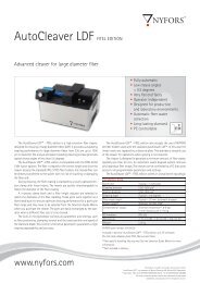
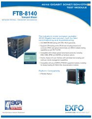
<strong>FTB</strong>-<strong>810</strong> NetBlazer SeriesTransport TesterCOMPLETE, FAST, INTUITIVE TRANSPORT TESTINGComprehensive, yet simple test suites for field technicians to easily turn up, validate and troubleshoottransport circuits covering all DSn/PDH and SONET/SDH interfaces up to 10 Gbit/s.KEY FEATURES AND B<strong>EN</strong>EFITSComplete test suite for DSn/PDH and SONET/SDH interfaces upto 10 Gbit/sSimpler reporting with integrated Wi-Fi and Bluetoothconnectivity capabilitiesSPEC SHEETSimplified BER testing with pass/fail indicators based on userdefinedthresholdsUnprecedented configuration simplicity with hybridtouchscreen/keypad navigation and data entryNo data interpretation errors with revolutionary new GUI on7-inch TFT screen, historical event logger, visual gauges and3D-icon depictions of pass/fail outcomesCentralized support for injection/monitoring of errors andalarms, trace messaging, overhead monitoring/manipulationand performance monitoring statisticsExtended field autonomy with compact, lightweight platformequipped with a long-duration battery packPLATFORM COMPATIBILITYPlatform<strong>FTB</strong>-1
The ultra-portable Choice for DSn/PDH and SONET/SDH Testing<strong>FTB</strong>-<strong>810</strong> NetBlazer Series Transport TesterWith a large installed base, testing DSn/PDH and SONET/SDH circuits, both in access and metro networks, continues to be adaily need that requires a test unit that is comprehensive, without sacrificing portability, speed or cost. Leveraging the powerful,intelligent <strong>FTB</strong>-1 handheld platform, the <strong>FTB</strong>-<strong>810</strong> NetBlazer series streamlines processes and empowers field technicians to testand validate DSn/PDH and SONET/SDH circuits efficiently.Powerful and FastAvailable in two hardware models (<strong>FTB</strong>-<strong>810</strong> and <strong>FTB</strong>-<strong>810</strong>G), the <strong>FTB</strong>-<strong>810</strong> NetBlazer series delivers fully integrated DSn/PDHand SONET/SDH testing and offers the industry’s largest touch screen with unprecedented configuration simplicity via hybridtouchscreen/keypad navigation. Platform connectivity is abundant via Wi-Fi, Bluetooth, Gigabit Ethernet or USB ports, making itaccessible in any environment.The Testing You Need for Any DSn/PDH or SONET/SDH Application› Installation, commissioning and maintenance of access and metro networks› Turn-up of DSn/PDH or SONET/SDH circuits› Performance assessment and troubleshooting› Performance monitoring of DSn/PDH and SONET/SDH circuits› Round-trip delay assessment of transport circuits› BER testing up to OC-192/STM-64<strong>FTB</strong>-<strong>810</strong>G: DSn/PDH and SONET/SDH Up to 10 Gbit/sIf the need is for transport testing at all rates up to10 Gbit/s, then the <strong>FTB</strong>-<strong>810</strong>G is the perfect solution.› SFP port for OC-3/12/48 or STM-1/4/16› SFP+ port for OC-192 or STM-64› RJ-48C and bantam ports for DS1 or E1› BNC port for DS3, E1/E3/E4,STS-1e/STS-3e or STM-0e/STM-1e› DS1/DS3 and E1/E3/E4 testing› OC-3/12/48/192 and STM-1/4/16/64 BER testingwith configurable threshold settings› Coupled, Decoupled and Through mode testing› Error and alarm insertion and monitoring› Overhead monitoring and manipulation› High-order and low-order mappings› Tandem connection monitoring (TCM)› Pointer manipulation, including pointer sequencetesting as per Telcordia GR-253, ANSI T1.105-03and ITU G.783› Performance monitoring as per G.821,G.826, G.828, G.829, M.2100, M.2101› Frequency analysis and offset generation› Automatic protection switching› Service-disruption time measurements› Round-trip delay measurements› Dual DS1/DS3 receiver (Rx) support› DS1 loop codes and NI/CSU emulation› DS1/DS3 autodetection of line code,framing and pattern› DS1 FDL and DS3 FEAC› Fractional T1/E1 testing› External clock sync support<strong>FTB</strong>-<strong>810</strong>: DSn/PDH and SONET/SDH Up to 2.5 Gbit/sIf the need is only for transport testing at all rates upto 2.5 Gbit/s, then the <strong>FTB</strong>-<strong>810</strong> is the answer.› SFP port for OC-3/12/48 or STM-1/4/16› RJ-48C and bantam ports for DS1 or E1› BNC port for DS3, E1/E3/E4, STS-1e/STS-3e orSTM-0e/STM-1e› DS1/DS3 and E1/E3/E4 testing› OC-3/12/48 and STM-1/4/16 BER testing withconfigurable threshold settings› Coupled, Decoupled and Through mode testing› Error and alarm insertion and monitoring› Overhead monitoring and manipulation› High-order and low-order mappings› Tandem connection monitoring (TCM)› Pointer manipulation, including pointer sequencetesting as per Telcordia GR-253, ANSI T1.105-03and ITU G.783› Performance monitoring as per G.821,G.826, G.828, G.829, M.2100, M.2101› Frequency analysis and offset generation› Automatic protection switching› Service-disruption time measurements› Round-trip delay measurements› Dual DS1/DS3 receiver (Rx) support› DS1 loop codes and NI/CSU emulation› DS1/DS3 autodetection of line code,framing and pattern› DS1 FDL and DS3 FEAC› Fractional T1/E1 testing› External clock sync support
<strong>FTB</strong>-<strong>810</strong> NetBlazer Series Transport TesterSetting a New GUI Standard: Unprecedented Simplicity in Configuration Setup and NavigationThe <strong>FTB</strong>-<strong>810</strong> NetBlazer’s intelligent situational configuration setup feature guides technicians through complete, accurate testingprocesses (suggestion prompts, help guides, etc.). It reduces navigation by combining associated testing functions on a single screen.Dedicated Quick-Action Buttons› Laser on/off› Test reset to clear the results and statistics while running a test› Report generation› Save or load test configurations› Quick error injectionStreamlined Navigation› Testing status can be maximized to fill the entire screen by simplyclicking on the Alarm Status button; whether the unit is in your hand oracross the room, test results can easily be determined with a simpleglance at the display screen› Simplified test structure definition using task-based test applicationselection, signal configuration front end and smart timeslot selection› Centralized functions: error/alarm management, performancemonitoring and overhead manipulation/monitoringAssorted Notifications› Optical power status available at all times› Pass/fail indication at all times› Pattern and clock synchronization› Electrical/optical power monitoring withvalid-range color indicator (optical interface)› Frequency offset with valid-range color indicator› Overhead overwrite indicator› Error/alarm injection› Alarm hierarchy pinpointing the root-cause (when possible)Key FeaturesSimplified BER TestingThe <strong>FTB</strong>-<strong>810</strong> NetBlazer series provides the ability to pre-configure bit-error-rate (BER) thresholds that are user-defined prior torunning the test. This allows for a simple pass/fail verdict at the conclusion of the test, leaving no room for misinterpretation ofthe test results.
<strong>FTB</strong>-<strong>810</strong> NetBlazer Series Transport TesterDecoupled ModeThe Decoupled mode enables the user to independently configure the Tx and Rx ports of the <strong>FTB</strong>-<strong>810</strong> NetBlazer module. Thisis required for testing the mapping and demapping functionality of a network element or at cross-connect points in the network.Through ModeThis mode is required for in-service monitoring of the network. The <strong>FTB</strong>-<strong>810</strong> NetBlazer can be inserted in-line on a specific link,and can then monitor and analyze the errors and alarms on that link while remaining non-intrusive.Simplified Error InjectionThis <strong>FTB</strong>-<strong>810</strong> feature enables the user to inject errors with a single click, from any screen. This allows technicians to ensure circuitcontinuity prior to starting a test. Furthermore, the error injection functionality can be pre-programmed for any given type of error,and not just for bit errors.Complete Overhead MonitoringThe <strong>FTB</strong>-<strong>810</strong> NetBlazer offers access to the entire SONET/SDH overhead (OH) bytes from a single page. Furthermore, byselecting any given OH byte, the user can retrieve additional detailed information about that byte without having to switch pages.
<strong>FTB</strong>-<strong>810</strong> NetBlazer Series Transport TesterSpecificationsSFP OPTICAL INTERFACESOC-3/STM-1 OC-12/STM-4 OC-48/STM-16Reach and wavelength 15 km; 1310 nm 40 km; 1310 nm 40 km; 1550 nm 80 km; 1550 nm 15 km; 1310 nm 40 km; 1310 nm 40 km; 1550 nm 80 km; 1550 nm 15 km; 1310 nm 40 km; 1310 nm 40 km; 1550 nm 80 km; 1550 nmTx level (dBm) –5 to 0 –2 to 3 –5 to 0 –2 to 3 –5 to 0 –2 to 3 –5 to 0 –2 to 3 –5 to 0 –2 to 3 –5 to 0 –2 to 3Rx operating range (dBm) –23 to –10 –30 to –15 –23 to –10 –30 to –15 –22 to 0 –27 to –9 –22 to 0 –29 to –9 –18 to 0 –27 to –9 –18 to 0 –28 to –9Transmit bit rate 155.52 Mbit/s ±4.6 ppm 622.08 Mbit/s ±4.6 ppm 2.48832 Gbit/s ±4.6 ppmFrequency offsetgeneration (ppm)±50 ±50 ±50Receive bit rate 155.52 Mbit/s ±100 ppm 622.08 Mbit/s ±100 ppm 2.48832 Gbit/s ±100 ppmOperationalwavelength range1261 to1360 nm1263 to1360 nm1430 to1580 nm1480 to1580 nm1270 to1360 nm1280 to1335 nm1430 to1580 nm1480 to1580 nm1260 to1360 nm1280 to1335 nmSpectral width 1 nm (–20 dB) 1 nm (–20 dB) 1 nm (–20 dB)Measurement accuracy(uncertainty)Frequency (ppm)Optical power (dB)±4.6±2Maximum Rxbefore damage (dBm) a 3 3 3Jitter complianceGR-253 (SONET)G.958 (SDH)±4.6±2GR-253 (SONET)G.958 (SDH)±4.6±21430 to1580 nmGR-253 (SONET)G.958 (SDH)Line coding NRZ NRZ NRZ1500 to1580 nmEye safety Class 1 Class 1 Class 1Connector b Dual LC Dual LC Dual LCTransceiver type c SFP SFP SFPSFP+ Optical InterfacesOC-192/STM-64 OC-192/STM-64 OC-192/STM-64Wavelength (nm) 1310 1550 1550Tx level (dBm) –6 to –1 –1 to 2 0 to 4Rx level sensitivity (dBm) –11 to 0.5 –14 to –1 –24 to –7Maximum reach 10 km 40 km 80 kmTransmission bit rate (Gbit/s) 9.95328 ±4.6 ppm 9.95328 ±4.6 ppm 9.95328 ±4.6 ppmFrequency offset generation (ppm) ±50 ±50 ±50Reception bit rate (Gbit/s) 9.95328 ±100 ppm 9.95328 ±100 ppm 9.95328 ±100 ppmTx operational wavelength range (nm) 1260 to 1355 1530 to 1565 1530 to 1565Measurement accuracy (uncertainty)Frequency (ppm)Optical power (dB)±4.6±2Maximum Rx before damage (dBm) a 5 5 3Jitter complianceGR-253 (SONET)G.825 (SDH)±4.6±2GR-253 (SONET)G.825 (SDH)±4.6±2GR-253 (SONET)G.825 (SDH)Eye safety Class 1 Class 1 Class 1Connector b LC LC LCTransceiver type d SFP+ SFP+ SFP+Notesa. In order not to exceed the maximum receiver power level before damage, an attenuator must be used.b. External adaptors can be used for other types of connectors.c. SFP compliance: The <strong>FTB</strong>-<strong>810</strong> selected SFP shall meet the requirements stated in the “Small Form-Factor Pluggable (SFP) Transceiver Multisource Agreement (MSA)”.The <strong>FTB</strong>-<strong>810</strong> selected SFP shall meet the requirements stated in the “Specification for Diagnostic Monitoring Interface for Optical Xcvrs”.d. SFP+ compliance: The <strong>FTB</strong>-<strong>810</strong> selected SFP+ shall meet the requirements stated in the SFP-8431 “Enhanced Small Form-Factor Pluggable Module SFP+” Transceiver Multisource Agreement (MSA)”.The <strong>FTB</strong>-<strong>810</strong> selected SFP+ shall meet the requirements stated in the “Specification for Diagnostic Monitoring Interface for Optical Xcvrs”.
<strong>FTB</strong>-<strong>810</strong> NetBlazer Series Transport TesterDSn/PDH and SONET/SDH Electrical InterfacesDS1 E1/2M E3/34M DS3/45M STS-1e/STM-0e/52M E4/140M STS-3e/STM-1e/155MTx pulse amplitude 2.4 to 3.6 V 3.0 V 2.37 V 1.0 ±0.1 V 0.36 to 0.85 V 1.0 ±0.1 Vpp 0.5 VTx pulse maskGR-499Figure 9.5G.703Figure 15G.703Figure 15G.703Figure 17GR-253Figure 4-10/4-11G.703Figure 18/19Tx LBO preamplificationCable simulationRx level sensitivity0-133 ft133-266 ft266-399 ft399-533 ft533-655 ft–22.5 dB–15.0 dB–7.5 dB0 dBFor 772 kHz:TERM: ≤ 26 dB(cable loss only)at 0 dBdsx TxDSX-MON: ≤ 26 dB(20 dB resistive loss +cable loss ≤ 6 dB)Bridge: ≤ 6 dB(cable loss only)For 1024 kHz:TERM: ≤ 6 dB(cable loss only)MON: ≤ 26 dB(20 dB resistive loss+ cable loss ≤ 6 dB)Bridge: ≤ 6 dB(cable loss only)For 1024 kHz:TERM: ≤ 6 dB(cable loss only)MON: ≤ 26 dB(20 dB resistive loss+ cable loss ≤ 6 dB)Bridge: ≤ 6 dB(cable loss only)For 17.184 MHz:TERM: ≤ 12 dB(coaxial cableloss only)MON: ≤ 26 dB(20 dB resistive loss+ cable loss ≤ 8 dB)DS-3GR-499Figure 9-80 to 225 ft225 to 450 ft45MG.703Figure 140 to 225 ft225 to 450 ft450 to 900 (927) ft 450 to 900 (927) ftFor 22.368 MHz:TERM: ≤ 10 dB(cable loss only)DSX-MON: ≤ 26.5 dB(21.5 dB resistive loss +cable loss ≤ 5 dB)For 25.92 MHz:TERM: ≤ 10 dB(cable loss only)MON: ≤ 25 dB(20 dB resistive loss+ cable loss ≤ 5 dB)For 70 MHz:TERM: ≤ 12 dB(coaxial cable loss only)MON: ≤ 26 dB(20 dB resistive loss+ cable loss ≤ 6 dB)STS-3eGR-253Figure 4-12,4-13, 4-140 to 225 ftSTM-1e/155MG.703Figure 22and 23For 78 MHz:TERM: ≤ 12.7 dB (coaxialcable loss only)MON: ≤ 26 dB(20 dB resistive loss+ cable loss ≤ 6 dB)Transmit bit rate1.544 Mbit/s±4.6 ppm2.048 Mbit/s±4.6 ppm2.048 Mbit/s±4.6 ppm34.368 Mbit/s±4.6 ppm44.736 Mbit/s±4.6 ppm51.84 Mbit/s±4.6 ppm139.264 Mbit/s±4.6 ppm155.52 Mbit/s±4.6 ppmFrequency offsetgenerationReceive bit rateMeasurement accuracy(uncertainty)Frequency (ppm)Electrical power (dB)Peak-to-peak voltage1.544 Mbit/s±140 ppm1.544 Mbit/s±140 ppm±4.6±1.5±10 % down to500 mVppIntrinsic jitter (Tx) ANSI T1.403 section 6.3GR-499 section 7.3Input jitter tolerance AT&T PUB 62411GR-499 section 7.32.048 Mbit/s±70 ppm2.048 Mbit/s±100 ppm±4.6±1.5±10 % down to500 mVpp2.048 Mbit/s±70 ppm2.048 Mbit/s±100 ppm±4.6±1.5±10 % down to500 mVpp34.368 Mbit/s±50 ppm34.368 Mbit/s±100 ppm±4.6±1.5±10 % down to500 mVppG.823 section 5.1 G.823 section 5.1 G.823 section 5.1G.751 section 2.344.736 Mbit/s±50 ppm44.736 Mbit/s±100 ppm±4.6±1.5±10 % down to200 mVppGR-449 section 7.3(categories I and II)G.823 section 7.1 G.823 section 7.1 G.823 section 7.1 GR-449 section 7.3(categories I and II)51.84 Mbit/s±50 ppm51.84 Mbit/s±100 ppm±4.6±1.5±10 % down to200 mVppGR-253 section5.6.2.2 (category II)GR-253 section5.6.2.2 (category II)139.264 Mbit/s±50 ppm139.264 Mbit/s±100 ppm±4.6±1.5±10 % down to200 mVpp155.52 Mbit/s±50 ppm155.52 Mbit/s±100 ppm±4.6±1.5±10 % down to200 mVppG.823 section 5.1 G.825 section 5.1GR-253 section 5.6.2.2G.823 section 7.1G.751 section 3.3G.825 section 5.2GR-253 section 5.6.2.3Line coding AMI and B8ZS AMI and HDB3 AMI and HDB3 HDB3 B3ZS B3ZS CMI CMIInput impedance(resistive termination)100 ohms ±5 %,balanced120 ohms ±5 %,balanced75 ohms ±5 %,unbalanced75 ohms ±5 %,unbalanced75 ohms ±5 %,unbalanced75 ohms ±5 %,unbalanced75 ohms ±10 %,unbalanced75 ohms ±5 %, unbalancedConnector type BANTAM and RJ-48C BANTAM and RJ-48C BNC BNC BNC BNC BNC BNCSynchronization interfacesExternal Clock DS1/1.5M External Clock E1/2M External Clock E1/2M Trigger 2 MHzTx pulse amplitude 2.4 to 3.6 V 3.0 V 2.37 V 0.75 to 1.5 VTx pulse mask GR-499 figure 9.5 G.703 figure 15 G.703 figure 15 G.703 figure 20Tx LBO preamplificationRx level sensitivityTypical power dBdsx+0.6 dBdsx (0-133 ft)+1.2 dBdsx (133-266 ft)+1.8 dBdsx (266-399 ft)+2.4 dBdsx (399-533 ft)+3.0 dBdsx (533-655 ft)TERM: ≤ 6 dB (cable loss only)(at 772 kHz for T1) DSX-MON: ≤ 26 dB(20 dB resistive loss + cable loss ≤ 6 dB)Bridge: ≤ 6 dB (cable loss only)TERM: ≤ 6 dB (cable loss only)MON: ≤ 26 dB (20 dB resistive loss+ cable loss ≤ 6 dB)Bridge: ≤ 6 dB (cable loss only)TERM: ≤ 6 dB (cable loss only)MON: ≤ 26 dB (resistive loss+ cable loss ≤ 6 dB)Bridge: ≤ 6 dB (cable loss only)Transmission bit rate 1.544 Mbit/s ± 4.6 ppm 2.048 Mbit/s ± 4.6 ppm 2.048 Mbit/s ± 4.6 ppmReception bit rate 1.544 Mbit/s ± 50 ppm 2.048 Mbit/s ± 50 ppm 2.048 Mbit/s ± 50 ppmIntrinsic jitter (Tx)ANSI T1.403 section 6.3GR-499 section 7.3Input jitter tolerance AT&T PUB 62411GR-499 section 7.3≤ 6 dB (cable loss only)G.823 section 6.1 G.823 section 6.1 G.703 table 11G.823 section 7.2G.813G.823 section 7.2G.813Line coding AMI and B8ZS AMI and HDB3 AMI and HDB3 G.823 section 7.1G.751 section 3.3Input impedance (resistive termination) 75 ohms ± 5 %, unbalanced 75 ohms ± 5 %, unbalanced 75 ohms ± 5 %, unbalanced 75 ohms ± 5 %, unbalancedConnector type BNC a BNC a BNC BNCNotea. Adaptation cable required for BANTAM.
<strong>FTB</strong>-<strong>810</strong> NetBlazer Series Transport TesterFunctional SONET and DSn SpecificationsNotesa. 1.5M (DS1) and 45M (DS3) interfaces described under SONET and DSn column.b. Not supported for E4 (140M).Functional SDH and PDH SpecificationsOptical interfaces OC-3, OC-12, OC-48, OC-192 Optical interfaces STM-1, STM-4, STM-16, STM-64Available wavelengths (nm) 1310, 1550 Available wavelengths (nm) 1310, 1550Electrical interfaces DS1, DS3, STS-1e, STS-3e Electrical interfaces a 1.5M (DS1), 2M (E1), 34M (E3), 45M (DS3), 140M (E4),STM-0e, STM-1eDS1 framing Unframed, SF, ESF, SLC-96 2M (E1) framing Unframed, PCM30, PCM31, PCM30 CRC-4, PCM31 CRC-4DS3 framing Unframed, M13, C-bit parity 8M (E2), 34M (E3), 140M (E4) framing Unframed (not applicable to E2), framedClocking Internal, loop-timed, external (BITS) Clocking Internal, loop-timed, external (MTS/SETS), 2 MHzMappingsVT1.5 Bulk, DS1 AU-3-TU-11, AU-4-TU-11 Bulk, 1.5M,VT2 Bulk, E1 AU-3 -TU-12, AU-4-TU-12 Bulk, 1.5M, 2MSTS-1 SPE Bulk, DS3 AU-3-Bulk, 34M, 45M, TU-3-AU-4 Bulk, 34M, 45MSTS-3c Bulk AU-4 Bulk, 140MSTS-12c/48c/192c, SPE Bulk AU-4-4c/16c/64c BulkSONET overhead analysis and manipulation A1, A2, J0, E1, F1, D1-D12, K1, K2, S1, M0, M1, E2,J1, C2, G1, F2, H4, Z3, Z4, Z5, N1, N2, Z6, Z7SDH overhead analysis and manipulation A1, A2, J0, E1, F1, D1-D12, K1, K2, S1, M0, M1G1, F2, F3, K3, N1, N2, K4, E2, J1, C2, H4Error insertionDS1 Framing bit, BPV, CRC-6, bit error, EXZ E1 (2M) Bit error, FAS, CV, CRC-4, E-bitDS3 BPV, C-bit, F-bit, P-bit, FEBE, bit error, EXZ E2 (8M), E3 (34M), E4 (140M) Bit error, FAS, CV (not applicable to E2)STS-1e, STS-3eOC-3, OC-12, OC-48, OC-192Section BIP (B1), line BIP (B2), path BIP (B3),BIP-2, REI-L, REI-P, REI-V, BPV, FAS, CV, bit errorSection BIP (B1), line BIP (B2), path BIP (B3),BIP-2, REI-L, REI-P, REI-V, FAS, bit errorSTM-0e, STM-1eSTM-1, STM-4, STM-16, STM-64RS-BIP (B1), MS-BIP (B2), HP-BIP (B3),MS-REI, HP-REI, LP-BIP-2, LP-REI, CV, FAS, bit errorRS-BIP (B1), MS-BIP (B2), HP-BIP (B3),MS-REI, HP-REI, LP-BIP-2, LP-REI, FAS, bit errorError measurementDS1 Framing bit, BPV, CRC-6, EXZ, bit error E1 (2M) Bit error, FAS, CV, CRC-4, E-bitDS3 BPV, C-bit, F-bit, P-bit, FEBE, bit error, EXZ E2 (8M), E3 (34M), E4 (140M) Bit error, FAS, CV (not applicable to E2)STS-1e, STS-3eSection BIP (B1), line BIP (B2), path BIP (B3),BIP-2, REI-L, REI-P, REI-V, BPV, FAS, CV, bit errorSTM-0e, STM-1eRS-BIP (B1), MS-BIP (B2), HP-BIP (B3),MS-REI, HP-REI, LP-BIP-2, LP-REI, CV, FAS, bit errorOC-3, OC-12, OC-48, OC-192Section BIP (B1), line BIP (B2), path BIP (B3),BIP-2, REI-L, REI-P, REI-V, FAS, bit errorSTM-1, STM-4, STM-16, STM-64RS-BIP (B1), MS-BIP (B2), HP-BIP (B3),MS-REI, HP-REI, LP-BIP-2, LP-REI, FAS, bit errorAlarm insertionDS1 LOS, RAI, AIS, OOF, pattern loss E1 (2M)LOS, LOS Mframe, LOF, AIS, TS16 AIS, RAI, RAI Mframe,pattern lossDS3 LOS, RDI, AIS, OOF, DS3 idle, pattern loss E2 (8M), E3 (34M), E4 (140M) LOS, LOF, RAI, AIS, pattern lossSTS-1e, STS-3e, OC-3,OC-12, OC-48, OC-192LOS, LOF-S, SEF, AIS-L, RDI-L, AIS-P, LOP-P, LOM,PDI-P, RDI-P, ERDI-PCD, ERDI-PPD, ERDI-PSD,UNEQ-P, AIS-V, LOP-V, RDI-V, ERDI-VCD, ERDI-VPD,ERDI-VSD, RFI-V, UNEQ-V, pattern lossSTM-0e, STM-1e, STM-1,STM-4, STM-16, STM-64LOS, LOF, OOF, MS-AIS, MS-RDI, AU-AIS, AU-LOP,H4-LOM, HP-ERDI-CD, HP-ERDI-PD, HP-ERDI-SD,LP-ERDI-CD, LP-ERDI-PD, LP-ERDI-SD, HP-UNEQ, TU-AIS,LP-RFI, LP-RDI, LP-RFI, LP-UNEQ, pattern lossAlarm detectionDS1 LOS, LOC, RAI, AIS, OOF, pattern loss E1 (2M)LOS, LOS Mframe, LOC, LOF, AIS, TS16 AIS, RAI, RAIMframe, pattern lossDS3 LOS, LOC, RDI, AIS, OOF, DS3 idle, pattern loss E2 (8M), E3 (34M), E4 (140M) LOS, LOC, LOF, RAI, AIS, pattern lossSTS-1e, STS-3e, OC-3,OC-12, OC-48, OC-192LOS, LOC, LOF-S, SEF, TIM-S, AIS-L, RDI-L, AIS-P,LOP-P, LOM, PDI-P, RDI-P, ERDI-PCD, ERDI-PPD,ERDI-PSD, PLM-P, UNEQ-P, TIM-P, AIS-V, LOP-V, RDI-V,ERDI-VCD, ERDI-VPD, ERDI-VSD, RFI-V, UNEQ-V, TIM-V,PLM-V, pattern lossSTM-0e, STM-1e, STM-1,STM-4, STM-16, STM-64LOS, RS-LOF, LOC, RS-OOF, RS-TIM, MS-AIS, MS-RDI,AU-AIS, AU-LOP, H4-LOM, HP-RDI, HP-ERDI-CD,HP-ERDI-PD, HP-ERDI-SD, LP-ERDI-CD, LP-ERDI-PD,LP-ERDI-SD, HP-PLM, HP-UNEQ, HP-TIM, TU-AIS, LP-RFI,LP-RDI, LP-RFI, LP-UNEQ, LP-TIM, LP-PLM, pattern lossFrequency alarm on all supported interfacesPatternsDS0 2E9-1, 2E11-1, 2E20-1, 1100, 1010, 1111, 0000,1-in-8, 1-in-16, 3-in-24, 32 bit programmable(inverted or non-inverted), bit errorsE0 (64K) 2E9-1, 2E11-1, 2E20-1, 1100, 1010, 1111, 00001-in-8, 1-in-16, 3-in-24, 32 bit programmable(inverted or non-inverted), bit errorsDS12E9-1, 2E11-1, 2E15-1, 2E20-1, 2E23-1, 2E31-1,E1 (2M)2E9-1, 2E11-1, 2E15-1, 2E20-1, 2E23-1, 2E31-1, 1100,1100, 1010, 1111, 0000, QRSS, 1-in-8, 1-in-16, 3-in-24,1010, 1111, 0000, 1-in-8, 1-in-16, 3-in-24, 32 bit32 bit programmable (inverted or non-inverted),programmable (inverted or non-inverted), bit errorsT1-DALY, 55-octet, bit errorsDS3 2E9-1, 2E11-1, 2E15-1, 2E20-1, 2E23-1, 2E31-1, 1100,1010, 1111, 0000, 1-in-8, 1-in-16, 3-in-24,32 bit programmable (inverted or non-inverted), bit errorsVT1.5/22E9-1, 2E11-1, 2E15-1, 2E20-1, 2E23-1, 2E31-1,1100, 1010, 1111, 0000, 1-in-8, 1-in-16,32 bit programmable (inverted or non-inverted), bit errorsSTS-1, STS-3c/12c/48c/192c2E9-1, 2E11-1, 2E15-1, 2E20-1, 2E23-1, 2E31-1,1100, 1010, 1111, 0000, 1-in-8, 1-in-16,32 bit programmable (inverted or non-inverted), bit errorsPattern loss and bit error generation and analysis supported on all patternsE3 (34M), E4 (140M) 2E9-1, 2E11-1, 2E15-1, 2E20-1, 2E23-1, 2E31-1, 1100,1010, 1111, 0000, 1-in-8, 1-in-16, 3-in-24 b , 32 bitprogrammable (inverted or non-inverted), bit errorsTU-11/12/3 2E9-1, 2E11-1, 2E15-1, 2E20-1, 2E23-1, 2E31-1, 1100,1010, 1111, 0000, 1-in-8, 1-in-16, 32 bitprogrammable (inverted or non-inverted), bit errorsAU-3/AU-4/AU-4-4c/16c/64c2E9-1, 2E11-1, 2E15-1, 2E20-1, 2E23-1, 2E31-1,1100, 1010, 1111, 0000, 1-in-8, 1-in-16,32 bit programmable (inverted or non-inverted), bit errors
<strong>FTB</strong>-<strong>810</strong> NetBlazer Series Transport TesterDSn/PDH and SONET/SDH Test FeaturesFrequency measurementsFrequency offset generationDual DSn receiversPerformance monitoringSupports clock frequency measurements (i.e., received frequency and deviation of the input signal clock from nominal frequency),displayed in ppm, for optical and electrical interfaces. Measurements are performed using a local oscillator.Supports offsetting the clock of the transmitted signal on a selected interface to exercise clock recovery circuitry on network elements.Supports two DS1 or DS3 receivers, allowing users to simultaneously monitor two directions of a circuit under test in parallel, resulting in quick isolation of the source of errors.The following ITU-T recommendations, and corresponding performance monitoring parameters, are supported on the <strong>FTB</strong>-<strong>810</strong>.ITU-T RecommendationPerformance monitoring statisticsG.821ES, EFS, EC, SES, UAS, ESR, SESR, DMG.826ES, EFS, EB, SES, BBE, UAS, ERS, SESR, BBERG.828ES, EFS, EB, SES, BBE, SEP, UAS, ESR, SESR, BBER, SEPIG.829ES, EFS, EB, SES, BBE, UAS, ESR, SESR, BBERM.2100ES, SES, UAS, ESR, SESRM.2101ES, SES, BBE, UAS, ESR, SESR, BBERPointer adjustment and analysis Generation and analysis of HO/AU and LO/TU pointer adjustments as per GR-253, and ITU-T G.707GenerationAnalysisPointer increment and decrementPointer incrementsPointer jump with or without NDFPointer decrements› Pointer valuePointer jumps (NDF, no NDF)› Pointer value and cumulative offsetService disruption time (SDT)measurementsRound-trip delay (RTD)measurementsAPS message control and monitoringSynchronization statusSignal label control and monitoringTandem connectionmonitoring (TCM) aPointer sequence testingM13 mux/demuxDS1 FDLDS1 loopcodesNI/CSU loopback emulationDS3 FEACDS1/DS3 auto detectionThrough modeNotesa. HOP and LOP supported as per ITU G.707 option 2.The service disruption time test tool measures the time during which there is a disruption of service due to the network switching from the active channels to the backup channels.Measurements: last disruption, shortest disruption, longest disruption, average disruption, total disruption, and service disruption count.The round-trip delay test tool measures the time required for a bit to travel from the <strong>FTB</strong>-<strong>810</strong> transmitter back to its receiver after crossing a far-end loopback.Measurements are provided on all supported <strong>FTB</strong>-<strong>810</strong> interfaces and mappings.Measurements: last, minimum, maximum, average; measurement count: no. of successful RTD tests and failed measurement count.Ability to monitor and set up automatic protection switching messages (K1/K2 byte of SONET/SDH overhead).Ability to monitor and set up synchronization status messages (S1 byte of SONET/SDH overhead).Ability to monitor and set up payload signal labels (C2, V5 byte of SONET overhead).Tandem connection monitoring (TCM), is used to monitor the performance of a subsection of a SONET/SDH path routed via different network providers.The <strong>FTB</strong>-<strong>810</strong> supports transmitting and receiving alarms and errors on a TCM link; also, transmission and monitoring of the tandem connection (TC)trace can be generated to verify the connection between TCM equipment.Error generation: TC-IEC, TC-BIP, TC-REI, TC-OEIError analysis: TC-IEC, TC-REI, TC-OEI, TC-VIOL (non-standardized alarm)Alarm generation: TC-RDI, TC-UNEQ, TC-ODI, TC-LTC, TC-IAISAlarm analysis: TC-TIM, TC-RDI, TC-UNEQ, TC-ODI, TC-LTC, TC-IAISPerform pointer sequence testing as per G.783, GR253 and T1.105-3 standards.Ability to multiplex/demultiplex a DS1 signal into/from a DS3 signal. (Note: E1 to DS3 mux/demux available with G.747 software option.)Support for DS1 Facility Data Link testing.Support for generation of DS1 in-band loopcodes with the availability of up to 10 pairs of user-defined loopcodes.Ability to respond to DS1 in-band/out-of-band loopcodes.Support for DS3 far-end alarms and loopback code words.Ability to automatically detect DS1/DS3 line coding, framing and test pattern.Perform Through mode analysis of any incoming electrical (DSn, PDH, SONET, SDH) and optical line (OC-3/STM-1, OC-12/STM-4, OC-48/STM-16, OC-192/STM-64) transparently.Additional FeaturesPower measurementPower-up and restoreSave and load configurationPass/fail analysisAlarm hierarchyReport generationEvent loggerRemote controlSupports power measurement at all times, displayed in dBm (dBdsx for DS1 and DS3), for optical and electrical interfaces.In the event of a power failure to the unit, the active test configuration and test logger are saved and restored upon boot-up.Store and load test configurations to/from a non-volatile USB memory stick or internal flash.Provides a pass/fail outcome with user-adjustable thresholds, based on bit error rate and/or service disruption time.Alarms are displayed according to a hierarchy based on root cause. Secondary effects are not displayed. This hierarchy serves to facilitate alarm analysis.Generate test reports on the unit or exported via USB.Log test results with absolute or relative time and date, details and duration of events, color-coded events and pass/fail outcome.Remote control through VNC.
<strong>FTB</strong>-<strong>810</strong> NetBlazer Series Transport TesterUpgradesSFP upgrades <strong>FTB</strong>-8190 SFP module; rates: 155/622 Mbit/s, 2.5/2.7 Gbit/s, GigE/FC/2FC; 1310 nm, LC connector, 15 km reach<strong>FTB</strong>-8191 SFP module; rates: 155/622 Mbit/s, 2.5/2.7 Gbit/s, GigE/FC/2FC; 1310 nm, LC connector, 40 km reachGeneral SpecificationsSize (H x W x D)Weight (without battery)TemperatureOperatingStorageRelative humidityBattery life (typical usage)Battery charging timeLanguagesORDERING INFORMATION<strong>FTB</strong>-8192<strong>FTB</strong>-8193<strong>FTB</strong>-8194<strong>FTB</strong>-8195<strong>FTB</strong>-8196130 mm x 252 mm x 56 mm (5 1 ⁄8 in x 9 15 ⁄16 in x 2 3 ⁄16 in)0.97 kg (2.1 lb)0 °C to 50 °C (32 °F to 122 °F)–40 °C to 70 °C (–40 °F to 158 °F)0 % to 93 %, non-condensingOver 4 hoursSFP module; rates: 155/622 Mbit/s, 2.5/2.7 Gbit/s, GigE/FC/2FC; 1550 nm, LC connector, 80 km reachSFP module; rates: 155/622 Mbit/s, 2.5/2.7 Gbit/s, GigE/FC/2FC; 1550 nm, LC connector, 40 km reachSFP module; rates: 155/622 Mbit/s; 1310 nm, LC connector, 15 km reachSFP module; rates: 155/622 Mbit/s; 1310 nm, LC connector, 40 km reachSFP module; rates: 155/622 Mbit/s; 1550 nm, LC connector, 80 km reachSFP+ upgrades <strong>FTB</strong>-8693 SFP+ modules, 9.953-10.709/11.3, 1310 nm, SMF, 10 km<strong>FTB</strong>-8694<strong>FTB</strong>-8695SFP+ modules, 8.5 9.953-10.709/11.1, 1550 nm, SMF, 40 kmSFP+ modules, 8.5 9.953-10.709/11.1, 1550 nm, SMF, 80 km2 hours from full discharge to full chargeEnglish, ChineseTest optionsSONET = SONET testingSDH = SDH testingSONET-SDH = SONET and SDH testingRate options155M = 155 Mbit/s (OC-3/STM-1)622M = 622 Mbit/s (OC-12/STM-4)2488M = 2.5 Gbit/s (OC-48/STM-16)Software options00 = Without software optionsDS3-G747 = G.747 test capabilityDS1-FDL = DS1 FDL test capabilityDUAL-RX = DS1/DS3 dual Rx testingDS3-FEAC = DS3 FEAC test capabilityTCM = Tandem connection monitoringDSn = DSn test capabilityPDH = PDH test capabilityNI-CSU = NI-CSU loopback emulationExample: <strong>FTB</strong>-<strong>810</strong>-SONET-155M-Dual-Rx<strong>FTB</strong>-<strong>810</strong>-XX-XX-XX<strong>FTB</strong>-<strong>810</strong>G-XX-XX-XXTest optionsSONET = SONET testingSDH = SDH testingSONET-SDH = SONET and SDH testingRate options155M = 155 Mbit/s (OC-3/STM-1)622M = 622 Mbit/s (OC-12/STM-4)2488M = 2.5 Gbit/s (OC-48/STM-16)9953M = 10 Gbit/s (OC-192/STM-64)Software options00 = Without software optionsDS3-G747 = G.747 test capabilityDS1-FDL = DS1 FDL test capabilityDUAL-RX = DS1/DS3 dual Rx testingDS3-FEAC = DS3 FEAC test capabilityTCM = Tandem connection monitoringDSn = DSn test capabilityPDH = PDH test capabilityNI-CSU = NI-CSU loopback emulation<strong>EXFO</strong> Corporate Headquarters > 400 Godin Avenue, Quebec City (Quebec) G1M 2K2 CANADA | Tel.: +1 418 683-0211 | Fax: +1 418 683-2170 | info@<strong>EXFO</strong>.comToll-free: +1 800 663-3936 (USA and Canada) | www.<strong>EXFO</strong>.com<strong>EXFO</strong> America 3400 Waterview Parkway, Suite 100 Richardson, TX 75080 USA Tel.: +1 972 761-9271 Fax: +1 972 761-9067<strong>EXFO</strong> Asia 100 Beach Road, #22-01/03 Shaw Tower SINGAPORE 189702 Tel.: +65 6333 8241 Fax: +65 6333 8242<strong>EXFO</strong> China 36 North, 3 rd Ring Road East, Dongcheng District Beijing 100013 P. R. CHINA Tel.: + 86 10 5825 7755 Fax: +86 10 5825 7722Room 1207, Tower C, Global Trade Center<strong>EXFO</strong> Europe Omega Enterprise Park, Electron Way Chandlers Ford, Hampshire S053 4SE <strong>EN</strong>GLAND Tel.: +44 23 8024 6<strong>810</strong> Fax: +44 23 8024 6801<strong>EXFO</strong> NetHawk Elektroniikkatie 2 FI-90590 Oulu, FINLAND Tel.: +358 (0)403 010 300 Fax: +358 (0)8 564 5203<strong>EXFO</strong> Service Assurance 270 Billerica Road Chelmsford, MA 01824 USA Tel.: +1 978 367-5600 Fax: +1 978 367-5700<strong>EXFO</strong> is certified ISO 9001 and attests to the quality of these products. This device complies with Part 15 of the FCC Rules. Operation is subject to the following two conditions: (1) this device may not causeharmful interference, and (2) this device must accept any interference received, including interference that may cause undesired operation. <strong>EXFO</strong> has made every effort to ensure that the information contained inthis specification sheet is accurate. However, we accept no responsibility for any errors or omissions, and we reserve the right to modify design, characteristics and products at any time without obligation. Unitsof measurement in this document conform to SI standards and practices. In addition, all of <strong>EXFO</strong>’s manufactured products are compliant with the European Union’s WEEE directive. For more information, pleasevisit www.<strong>EXFO</strong>.com/recycle. Contact <strong>EXFO</strong> for prices and availability or to obtain the phone number of your local <strong>EXFO</strong> distributor.For the most recent version of this spec sheet, please go to the <strong>EXFO</strong> website at www.<strong>EXFO</strong>.com/specs.In case of discrepancy, the Web version takes precedence over any printed literature.SP<strong>FTB</strong><strong>810</strong>.1AN© 2011 <strong>EXFO</strong> Inc. All rights reserved.2008Printed in Canada 11/06