MIL-STD-883E METHOD 2011.7 22 March 1989 1 METHOD 2011.7 ...
MIL-STD-883E METHOD 2011.7 22 March 1989 1 METHOD 2011.7 ...
MIL-STD-883E METHOD 2011.7 22 March 1989 1 METHOD 2011.7 ...
- No tags were found...

You also want an ePaper? Increase the reach of your titles
YUMPU automatically turns print PDFs into web optimized ePapers that Google loves.
<strong>MIL</strong>-<strong>STD</strong>-<strong>883E</strong>3.1.3 Test condition D - Wire pull (double bond). This procedure is identical to that of test condition C, except that the pullis applied by inserting a hook under the lead wire (attached to die, substrate or header or both ends) with the device clampedand the pulling force applied approximately in the center of the wire in a direction approximately normal to the die or substratesurface or approximately normal to a straight line between the bonds. When a failure occurs, the force causing the failureand the failure category shall be recorded. The minimum bond strength shall be taken from table I. Figure 2011-1 may beused for wire diameters not specified in table I. For wire diameter or equivalent cross section >0.005 inch, where a hook willnot fit under the wire, a suitable clamp can be used in lieu of a hook.3.1.4 Test condition F - Bond shear (flip chip). This test is normally employed for internal bonds between asemiconductor die and a substrate to which it is attached in a face-bonded configuration. It may also be used to test thebonds between a substrate and an intermediate carrier or secondary substrate to which the die is mounted. A suitable tool orwedge shall be brought in contact with the die (or carrier) at a point just above the primary substrate and a force appliedperpendicular to one edge of the die (or carrier) and parallel to the primary substrate, to cause bond failure by shear. Whena failure occurs, the force at the time of failure, and the failure category shall be recorded.3.1.5 Test condition G - Push-off test (beam lead). This test is normally employed for process control and is used on asample of semiconductor die bonded to a specially prepared substrate. Therefore, it cannot be used for random sampling ofproduction or inspection lots. A metallized substrate containing a hole shall be employed. The hole appropriately centered,shall be sufficiently large to provide clearance for a push tool, but not large enough to interfere with the bonding areas. Thepush tool shall be sufficiently large to minimize device cracking during testing, but not large enough to contact the beamleads in the anchor bond area. Proceed with push-off tests as follows: The substrate shall be rigidly held and the push toolinserted through the hole. The contact of the push tool to the silicon device shall be made without appreciable impact (lessthan 0.01 inch/minute (0.254 mm/minute ) and forced against the underside of the bonded device at a constant rate. Whenfailure occurs, the force at the time of failure, and the failure category shall be recorded.3.1.6 Test condition H - Pull-off test (beam lead). This test is normally employed on a sample basis on beam lead deviceswhich have been bonded down on a ceramic or other suitable substrate. The calibrated pull-off apparatus (see 2) shallinclude a pull-off rod (for instance, a current loop of nichrome or Kovar wire) to make connection with a hard setting adhesivematerial (for instance, heat sensitive polyvinyl acetate resin glue) on the back (top side) of the beam lead die. The substrateshall be rigidly installed in the pull-off fixture and the pull-off rod shall make firm mechanical connection to the adhesivematerial. The device shall be pulled within 5 degrees of the normal to at least the calculated force (see 3.2), or until the die isat 2.54 mm (0.10 inch) above the substrate. When a failure occurs, the force at the time of failure, the calculated force limit,and the failure category shall be recorded.3.2 Failure criteria. Any bond pull which results in separation under an applied stress less than that indicated in table I asthe required minimum bond strength for the indicated test condition, composition, and construction shall constitute a failure.3.2.1 Failure category. Failure categories are as follows: When specified, the stress required to achieve separation andthe category of separation or failure shall be recorded.a. For internal wire bonds:(a-1)(a-2)(a-3)(a-4)(a-5)(a-6)(a-7)(a-8)Wire break at neckdown point (reduction of cross section due to bonding process).Wire break at point other than neckdown.Failure in bond (interface between wire and metallization) at die.Failure in bond (interface between wire and metallization) at substrate, package post, or other than die.Lifted metallization from die.Lifted metallization from substrate or package post.Fracture of die.Fracture of substrate.<strong>METHOD</strong> <strong>2011.7</strong><strong>22</strong> <strong>March</strong> <strong>1989</strong>2
<strong>MIL</strong>-<strong>STD</strong>-<strong>883E</strong>TABLE I. Minimum bond strength.TestconditionWirecompositionand diameter1/Construction2/Minimum bond strength (grams force)Pre seal Post seal and any otherprocessing and screeningwhen applicableA --- --- Given inapplicabledocumentGiven in applicabledocumentC or D AL 0.0007 inAU 0.0007 inC or D AL 0.0010 inAU 0.0010 inWire 1.52.0Wire 2.53.01.01.51.52.5C or D AL 0.00125 inAU 0.00125 inWire Same bond strength limitsas the 0.0013 in wireC or D AL 0.0013 inAU 0.0013 inC or D AL 0.0015 inAU 0.0015 inC or D AL 0.0030 inAU 0.0030 inWire 3.04.0Wire 4.05.0Wire 12.015.02.03.02.54.08.012.0F Any Flip-clip 5 grams-force xnumber of bonds (bumps)G or H Any Beam lead 30 grams force in accordance withlinear millimeter of nominal undeformed(before bonding) beam width. 3/1/ For wire diameters not specified, use the curve of figure 2011-1 to determine the bondpull limit.2/ For ribbon wire, use the equivalent round wire diameter which gives the samecross-sectional area as the ribbon wire being tested.3/ For condition G or H, the bond strength shall be determined by dividing the breakingforce by the total of the nominal beam widths before bonding.4. SUMMARY. The following details shall be specified in the applicable acquisition document:a. Test condition letter (see 3).b. Minimum bond strength if other than specified in 3.2 or details of required strength distributions if applicable.* c. Sample size number and accept number or number and selection of bond pulls to be tested on each device, andnumber of devices, if other than 4.d. For test condition A, angle of bond peel if other than 90°, and bond strength limit (see 3.2).e. Requirement for reporting of separation forces and failure categories, when applicable (see 3.2.1).<strong>METHOD</strong> <strong>2011.7</strong><strong>22</strong> <strong>March</strong> <strong>1989</strong>4
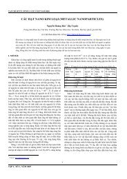
<strong>MIL</strong>-<strong>STD</strong>-<strong>883E</strong>NOTE: The minimum bond strength should be taken from table I. Figure 2011-1may be used for wire diameters not specified in table I.FIGURE 2011-1. Minimum bond pull limits.5<strong>METHOD</strong> <strong>2011.7</strong><strong>22</strong> <strong>March</strong> <strong>1989</strong>
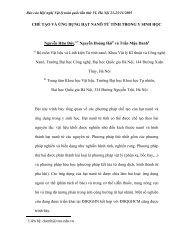
<strong>MIL</strong>-<strong>STD</strong>-<strong>883E</strong>FIGURE 2011-2. Wire loop angle.FIGURE 2011-3. Flat loop wire pull testing.<strong>METHOD</strong> <strong>2011.7</strong><strong>22</strong> <strong>March</strong> <strong>1989</strong>6