

AGA-9 Measurement of Gas by Multipath Ultrasonic Meters
AGA-9 Measurement of Gas by Multipath Ultrasonic Meters
AGA-9 Measurement of Gas by Multipath Ultrasonic Meters
- No tags were found...

Create successful ePaper yourself
Turn your PDF publications into a flip-book with our unique Google optimized e-Paper software.
to be ±0.4 below Q t . Figure 1 is a graphicalrepresentation <strong>of</strong> these performance requirements asshown in <strong>AGA</strong> 9.Zero-flow reading
techniques are also permitted such as polynomial andmulti-point linearization.If a USM is calibrated, <strong>AGA</strong> 9 discusses requirements thecalibration facility must adhere to. These includedocumenting the name and address <strong>of</strong> the manufacturerand test facility, model and serial number <strong>of</strong> the meter,firmware revision and date, date <strong>of</strong> test, upstream anddownstream piping conditions, and a variety <strong>of</strong> other datathat is to be included in the test report. The test facilitymust maintain these records for a minimum <strong>of</strong> 10 years.INSTALLATION REQUIREMENTSSection 7 discusses many <strong>of</strong> the variables the designershould take into consideration when using USMs. Some<strong>of</strong> the information that went into this section was basedupon actual testing, but much was based upon a comfortlevel that was achieved with other electronicmeasurement products such as turbine and orifice meters.In the environmental section basic information that thedesigner should be mindful <strong>of</strong> is discussed. This includesambient temperature, vibration and electrical noiseconsiderations.The piping configuration section is probably one <strong>of</strong> themore important sections, and yet it was developed withonly limited empirical data. This is due in part to the lack<strong>of</strong> test data that was available in 1998. For instance,Section 7.2.2 <strong>of</strong> <strong>AGA</strong> 9 discusses upstream piping issues.The intent here is to provide the designer with some basicdesigns that will provide accurate measurement. It states“Recommend upstream and downstream pipingconfiguration in minimum length — one without a flowconditioner and one with a flow conditioner — that willnot create an additional flow-rate measurement error <strong>of</strong>more than +0.3% due to the installation configuration.This error limit should apply for any gas flow ratebetween q min and q max . The recommendation should besupported <strong>by</strong> test data.” In other words, the manufactureris required to let the designer know what type <strong>of</strong> piping ispermitted upstream so that the impact on accuracy willnot be greater than 0.3%.In 1998 most manufacturers felt their product wasrelatively insensitive to upstream piping issues. Much hasbeen published since that date, and, as a consequence <strong>of</strong>this data, and the desire to provide the highest level <strong>of</strong>accuracy, most users have elected to use a highperformanceflow conditioner with their USM. Testinghas shown that the use <strong>of</strong> a 19-tube bundle, typical withturbine and orifice metering, will not improve the USMperformance, and in most cases actually will degradeaccuracy [Ref 7].Some testing had been completed on step changesbetween the USM and the upstream and downstreampiping [Ref 16]. The data basically showed the meter tobe relatively insensitive to these changes. Based upontypical tolerances <strong>of</strong> pipe manufacturers, it was agreed touse a tolerance <strong>of</strong> 1%. In reality the step change is muchless, especially if the designer specifies machine-honedpipe.Regarding the surface finish and upstream lengths <strong>of</strong>piping require, <strong>AGA</strong> 9 has been silent on this issue.Many customers prefer the finish to be less than 300 μinch (micro-inch) because they feel it is easier to cleanshould the piping become dirty. However, <strong>AGA</strong> 9 has nosuch requirement.Just like a turbine meter, a USM requires temperaturemeasurement. <strong>AGA</strong> 9 recommends the thermowell beinstalled between 2D and 5D downstream <strong>of</strong> the USM ona uni-directional installation. It states the thermowellshould be at least 3D from the meter on a bi-directionalinstallation. This was based on some work done at SwRIunder the direction <strong>of</strong> GRI in the 1990’s. They found aslight influence at 2D upstream <strong>of</strong> USMs during sometesting and thus the committee settled on 3D as areasonable distance.A discussion on USMs must include flow conditioners.The promise <strong>of</strong> the USM was they could handle a variety<strong>of</strong> upstream piping conditions, and that there was nopressure drop. However, today the users are looking toreduce measurement uncertainty to a minimum value.Thus, most designers today do specify a highperformanceflow conditioner.No discussion on USMs would be complete withouttalking about how one gets from the meter’s uncorrectedoutput to a corrected value for billing. Since the USM isa linear meter, like a turbine, rotary and diaphragm (flowrate is linear with velocity), the same equations used forthese devices apply to the USM. That is, to convertuncorrected flow from a USM to corrected flow, theequations detailed in <strong>AGA</strong> 7 are used.FIELD VERIFICATIONSection 8 briefly discusses field verification requirements.Since each USM provides somewhat different s<strong>of</strong>tware tointerface with the meter, <strong>AGA</strong> 9 was not too specificabout how to verify field performance. Rather they left itup to the manufacturer to provide a written fieldverification procedure that the operator could follow.Many papers have been given on this subject and to somedegree the field verification procedures are metermanufacturerdependent [Ref 17 & 18].Typically today the operator would check the basicdiagnostic features including velocity pr<strong>of</strong>ile, speed-<strong>of</strong>sound<strong>by</strong> path, transducer performance, signal to noiseratios and gain. One additional test is to compare themeter’s reported SOS with that computed <strong>by</strong> a programbased upon <strong>AGA</strong> 8 [Ref 19].At the time <strong>of</strong> the first release there was no universallyexcepted document that discussed how to computer SOS.However, in 2003 <strong>AGA</strong> published <strong>AGA</strong> Report No. 10,Speed <strong>of</strong> Sound in Natural <strong>Gas</strong> and Other RelatedHydrocarbon <strong>Gas</strong>es [Ref 20]. This document, based
upon <strong>AGA</strong> 8, provides the foundation for computing SOSthat most s<strong>of</strong>tware uses today.<strong>AGA</strong> 9 – SECOND REVISION CHANGESA significant amount <strong>of</strong> testing has been performed since1998. More than two thousand USMs have beeninstalled, with the majority in fiscal measurementapplications. For more than 5 years the TMC committeehas been working on the second revision. At the time <strong>of</strong>this paper Paul LaNasa <strong>of</strong> CPL & Associates and WarrenPeterson <strong>of</strong> TransCanada Pipeline are co-chairing thisrevision. Revision 2 was sent out for ballot late in 2005.Comments were collected and resolved through a series <strong>of</strong>meetings at the <strong>AGA</strong> TMC meetings. Two separatemeetings were held to resolve mostly editorial comments.The final version will incorporate more requirements onthe USM. These include changes and/or added discussionon meter accuracy, flow calibration, audit trail, meter andflow conditioner qualification, pressure effects, transducerand electronics change out, piping lengths, ultrasonicnoise from control valves, and a discussion on uncertaintyanalysis.Section 2, Terminology, Units, and DefinitionsThis version expands from Terminology to provide to alsoinclude Units and Definitions. Many new definitionswere added to be more consistent with other <strong>AGA</strong>documents. Significant additions include Accuracy,Confidence Level, Discrete Error Values, Error,Maximum SOS Path Spread, Repeatability andReproducibility just to name a few. The intent is toprovide the reader with a clearer understanding <strong>of</strong> thevarious terms used throughout the document.Section 3, Operating ConditionsSection 3 remains similar to the original version but hasone significant addition to discuss acoustic noise. Duringthe past several years, designers, users and manufacturershave all learned more about the impact <strong>of</strong> control valveson the USM. This release <strong>of</strong> <strong>AGA</strong> 9 provides moreinformation to caution the user about the potentialinterference with the USM should a control valve belocated too close, or the differential pressure to excessive.<strong>Ultrasonic</strong> noise from a control valve can render the USMinoperative [Ref 21]. As all manufacturers use differenttransducer designs and path layouts, there can besignificant differences in recommendations for addressingthe noise from control valves.Section 4, Meter RequirementsSection 4 also remains similar to the original version butwith a couple <strong>of</strong> additions. The original version requiredthe meter to have a uniform bore throughout the meter.This version will permit the measurement section to havea different bore than the upstream and downstream pipingthrough the use <strong>of</strong> a taper on the inlet and outlet.Additionally this version will require the meter’smeasurement section to have a constant bore with 0.5%,effectively eliminating the use <strong>of</strong> out-<strong>of</strong>-round pipe.A section on Quality Assurance has been added to requirethe manufacturer to have a comprehensive qualityassurance program in place.An option has been added to the Output SignalSpecifications Section that would permit selecting whatthe frequency output should do in the event the meter isover-ranged. That is, should the frequency go to zero orto some user-selected value. This is important in theevent the meter is over-ranged (traditionally the frequencywould go to zero) and the output is used for automatic runswitching. If the meter’s output simply went to zero, theautomatic run switching would not activate an additionalrun since the frequency would normally be zero.A section on component replacement was also included todiscuss the requirements <strong>of</strong> the manufacturer to meetcertain accuracy requirements in the event <strong>of</strong> componentreplacement. This includes transducers, cables, electronicparts and s<strong>of</strong>tware.Section 5, Meter Performance RequirementsSection 5, Meter Performance Requirements, hasundergone some changes as well. First, the definitionsthat were once part <strong>of</strong> this section have been move toSection 2. New accuracy requirements <strong>of</strong> Speed <strong>of</strong> SoundDeviation have been incorporated (±0.2%). Additionallythe Zero Flow Reading has been reduced from 0.04 ft/s to0.02 ft/s for each acoustic path. This should help improvethe low velocity performance <strong>of</strong> the USM. Basic meteraccuracy remains the same.One important change will be the requirement for flowcalibration if the USM is to be used for fiscalmeasurement. In the first release <strong>of</strong> <strong>AGA</strong> 9, since therewere no calibration facilities in North America that couldperform full-scale calibrations for 8-inch and largermeters, the committee decided that flow calibration wasoptional. However, today there are two facilities in NorthAmerica that can perform full-scale calibrations on 30-inch meters. The many benefits <strong>of</strong> flow calibrating theUSM has been well documented [Ref 21]. Thus, with theinterest in reducing uncertainty, calibration will berequired.Today, the issue <strong>of</strong> calibrating a meter at a differentpressure than it is operated at is not discussed as much asbefore. Most users recognize that meters that aredesigned to be installed in ANSI 600 applications havevery little shift over the typical operating pressure rangethat they will be installed. Ss the technology expands tointo lower pressures applications such as Distribution,calibration pressure may be more important. However,for the traditional Transmission applications in NorthAmerica, specifying a calibration pressure is typically notrequired or done.
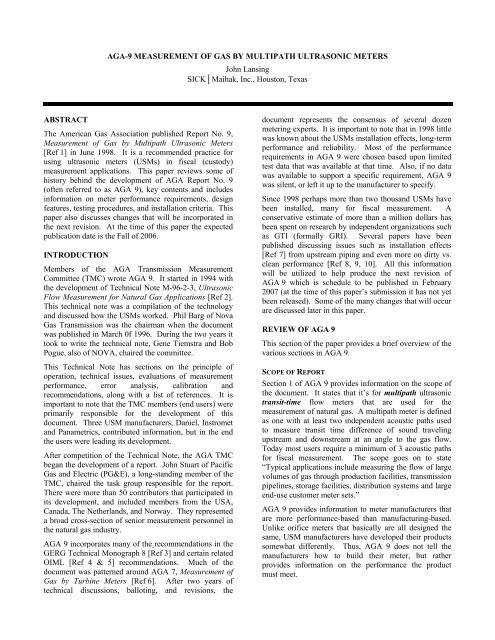
Section 6, Individual Meter and Metering PackageTesting RequirementsThe original <strong>AGA</strong> 9 section title was Individual MeterTesting Requirements but this version it has beenexpanded to include the metering package (flowconditioner and associated piping). Since most designersinclude piping and a flow conditioner when calibratingthe UM, the section was change to accommodate this.Much <strong>of</strong> this section remains the same but there are someadditions including the Speed <strong>of</strong> Sound (SOS) beingwithin ±0.2% compared to the theoretical speed <strong>of</strong> soundfrom <strong>AGA</strong> 10 [Ref. 10].For applications that are fiscal measurement, flowcalibration is required. The new recommended flow ratesare 2.5, 5, 10, 25, 50, 75 and 100 percent <strong>of</strong> Q max . Thisessentially equates to calibrating from something like 2.5fps (0.75 m/s) to 100 fps (30 m/s). Today most users limittheir meter design to operate the meter at no greater than80 fps. Thus it is common for many to calibrate from 1-80 fps (0.3-25 m/s). Again, these are onlyrecommendations and the user is still permitted to includemore than the recommendation.The subject <strong>of</strong> meter accuracy relative to different flowconditioners and the uncertainty <strong>of</strong> the various calibrationfacilities has been addressed in this section. The issue issome flow conditioners may cause a shift in meteraccuracy compared to the same meter calibrated without aflow conditioner. Since virtually all designers specifyusing a flow conditioner, some additional tolerance wassuggested to allow for small changes in the meter factorwhen the UM is used with a flow conditioner (accuracyspecifications in this section apply only to the meter).In the past when meters were calibrated the questionabout what to do with a meter that did not meet the drycalibration requirements as spelled out in Section 5. Inorder to address this, the 2007 version <strong>of</strong> <strong>AGA</strong> 9 nowpermits an additional 0.3% increase in the meter accuracytolerance to take into consideration the potential influencethe piping and flow conditioner(s) may have. This a newparagraph has been added that states the following: “Ifthe meter calibration adjustment factor exceeds the errorlimit <strong>of</strong> 1.0% for large meters and 1.3% for small metersbetween q t and q max , against the calibration facilityreference, then further investigation is recommended.”This now permits the user to accept a meter that is outsidethe dry calibration accuracy requirements if they feel theother performance requirements <strong>of</strong> the meter have beenmet (linearity, repeatability, etc.).In the sub section on Calibration Reports some additionaldocumentation if now required <strong>by</strong> the test facility. Thisincludes the serial number <strong>of</strong> the flow conditioner andpiping (if available), identification <strong>of</strong> the type <strong>of</strong> meteradjustment method (single FWME, piece-wiselinearization, etc), and numbering <strong>of</strong> the pages.Section 7, Installation RequirementsIn Section 7, Installation Requirements includes tworecommended default piping designs, one for unidirectionaland one for bi-directional applications. Forthe uni-directional design there is a recommendation <strong>of</strong>two 10D upstream spools with a flow conditioner in themiddle (10D from the meter). For the bi-directionaldesign, both upstream and downstream recommendationwould be two 10D spools with flow conditioners againlocated 10D from the meter. See Figure 2 for an example<strong>of</strong> the piping design recommendations. These are onlyrecommendations and the use <strong>of</strong> the optional Tee orElbow is strictly optional.Surface finish <strong>of</strong> the piping used with a USM has nowbeen discussed. Section 7.2.4 states “Experience hasshown that a meter tube internal surface <strong>of</strong> 250 µinch Raor better smoothness can be advantageous in minimizingcontamination build up.” However, this version <strong>of</strong> <strong>AGA</strong>9 stops short <strong>of</strong> requiring that the surface finish be 250µinch Ra or better. Thus it is only a recommendation andthere is no requirement for using honed pipe.The first release <strong>of</strong> <strong>AGA</strong> 9 indicated the thermowellshould be at least 3D from the meter for bi-directionalapplications. Some have interpreted this to mean that13D from the meter is satisfactory. This version will is nomore specific and requires the location to be between 3and 5D downstream <strong>of</strong> the meter.A new section on meter tube ports has been added. Therehave been some instances where large ports were includedin the upstream and downstream piping. These openingshave caused unusual calibrations characteristics. As aresult <strong>AGA</strong> 9 now states the port diameter should notexceed 6% <strong>of</strong> the pipe diameter. Inspection ports can beincluded up to 0.75” in diameter, where physicallypractical. From <strong>AGA</strong> 9, it states “Meter tube inspectionports, if utilized, should be located a minimum <strong>of</strong> 3Ddownstream and/or 3D upstream <strong>of</strong> the ultrasonictransducers and/or upstream <strong>of</strong> the flow conditioner inletposition.” This is to minimize any potential interferencewith the flow pr<strong>of</strong>ile.
Figure 2 – Recommended Default Unidirectional and Bi-directional InstallationsThe subsection on Maintenance has been expanded todiscuss issues that may occur in the field such ascontamination. This section also discusses borescopeinspection and the benefits <strong>of</strong> identifying potentialinternal deposits that can impact accuracy.Section 8, Field Verification TestsThis section basically remains unchanged. It simplyindicates the user should check their meter periodically toinsure proper operation.Section 9, <strong>Ultrasonic</strong> Meter <strong>Measurement</strong> UncertaintyDeterminationThis is a new section that discusses the uncertainty <strong>of</strong> theUSM. The types <strong>of</strong> uncertainties included are metercalibration, field, secondary instrumentation and areference to an analysis procedure that is included in anAppendix. This will help the designer understand all thevarious components that contribute to the total installeduncertainty <strong>of</strong> using a USM.CONCLUSIONSDuring the past several years much has been learnedabout the use <strong>of</strong> ultrasonic meters. Testing has beenconducted not only <strong>by</strong> a variety <strong>of</strong> agencies such as GTI(formally GRI), but <strong>by</strong> end users and calibration facilities.This information is be used to provide more guidance tothe designer and user <strong>of</strong> USMs.In the 1990’s metering accuracy was important, but todayit is even more critical now that the price <strong>of</strong> natural gas isconsistently above $5 per thousand cubic feet, and attimes approaching $15 per thousand cubic feet. As aconsequence designers are challenged to further reduceuncertainty. Requiring flow calibration, providingrecommendations on piping, and adding accuracyrequirements for SOS are all intended to reduceuncertainty in the field.Today, in North America, most transmission and manydistribution companies are using USMs for fiscalmeasurement. Even though ultrasonic meters have beenused for more than a decade, the industry is still learning.During the coming years certainly improvements <strong>by</strong> allmanufacturers will continue. The second release <strong>of</strong><strong>AGA</strong> 9, which is expected to be available <strong>by</strong> March 2007,will provide a substantial improvement in the document.However, just like all <strong>AGA</strong> documents, there werefeatures that did not make this release. Most certainlythere will be a future revision to address these andincorporate additional lessons learned about thistechnology.
REFERENCES1. <strong>AGA</strong> Report No. 9, <strong>Measurement</strong> <strong>of</strong> <strong>Gas</strong> <strong>by</strong><strong>Multipath</strong> <strong>Ultrasonic</strong> <strong>Meters</strong>, June 1998, American<strong>Gas</strong> Association, 1515 Wilson Boulevard, Arlington,VA 222092. <strong>AGA</strong> Engineering Technical Note M-96-2-3,<strong>Ultrasonic</strong> Flow <strong>Measurement</strong> for Natural <strong>Gas</strong>Applications, American <strong>Gas</strong> Association, 1515Wilson Boulevard, Arlington, VA 222093. GERG Technical Monograph 8 (1995), PresentStatus and Future Research on Multi-path <strong>Ultrasonic</strong><strong>Gas</strong> Flow <strong>Meters</strong>, Christian Michelsen Research AS,the GERG Project Group and Programme CommitteeNo. 2 - Transmission and Storage, Groupe EuropéenDe Recherches Gazières4. OIML R 6 General provisions for gas volume meters,1989 (E), International Recommendation,Organization Internationale de Métrologie Légale,Bureau International de Métrologie Légale, 11, rueTurgot - 75009 Paris - France5. OIML D 11 General requirements for electronicmeasuring instruments, 1994 (E), InternationalDocument, Organization Internationale de MétrologieLégale, Bureau International de Métrologie Légale,11, rue Turgot - 75009 Paris - France6. <strong>AGA</strong> Transmission <strong>Measurement</strong> Committee ReportNo. 7, <strong>Measurement</strong> <strong>of</strong> <strong>Gas</strong> <strong>by</strong> Turbine <strong>Meters</strong>,American <strong>Gas</strong> Association, 1515 Wilson Boulevard,Arlington, VA 222097. T. A. Grimley, <strong>Ultrasonic</strong> Meter InstallationConfiguration Testing, <strong>AGA</strong> Operations Conference,2000, Denver, CO8. John Lansing, Dirty vs. Clean <strong>Ultrasonic</strong> Flow MeterPerformance, <strong>AGA</strong> Operations Conference, 2002,Chicago, IL9. John Stuart, Rick Wilsack, Re-Calibration <strong>of</strong> a 3-Year Old, Dirty, <strong>Ultrasonic</strong> Meter, <strong>AGA</strong> OperationsConference, 2001, Dallas, TX10. James N. Witte, <strong>Ultrasonic</strong> <strong>Gas</strong> <strong>Meters</strong> from FlowLab to Field: A Case Study, <strong>AGA</strong> OperationsConference, 2002, Chicago, IL11. Code <strong>of</strong> Federal Regulations, Title 49 —Transportation, Part 192, (49 CFR 192),Transportation <strong>of</strong> Natural <strong>Gas</strong> and Other <strong>Gas</strong> <strong>by</strong>Pipeline: Minimum Federal Safety Standards, U.S.Government Printing Office, Washington, DC 2040212. NFPA 70, National Electrical Code, 1996 Edition,National Fire Protection Association, BatterymarchPark, Quincy, MA 0226913. John Lansing, Basics <strong>of</strong> <strong>Ultrasonic</strong> Flow <strong>Meters</strong>,ASGMT 2000, Houston, TX14. Klaus Zanker, Diagnostic Ability <strong>of</strong> the Daniel Four-Path <strong>Ultrasonic</strong> Flow Meter, Southeast Asia Flow<strong>Measurement</strong> Workshop, 2003, Kuala Lumpur,Malaysia15. Dr. Jim Hall, William Freund, Klaus Zanker & DaleGoodson, Operation <strong>of</strong> <strong>Ultrasonic</strong> Flow <strong>Meters</strong> atConditions Different Than Their Calibration,NSFMW 2002, Scotland16. Umesh Karnik & John Geerlings, Effect <strong>of</strong> Steps andRoughness on Multi-Path <strong>Ultrasonic</strong> <strong>Meters</strong>, ISFFM2002, Washington, DC17. John Lansing, Smart Monitoring and Diagnostics for<strong>Ultrasonic</strong> <strong>Meters</strong>, NSFMW 2000, Scotland18. John Lansing, Using S<strong>of</strong>tware to Simplify USMMaintenance, <strong>AGA</strong> Operations Conference, 2003,Kissimmee, FL19. <strong>AGA</strong> Transmission <strong>Measurement</strong> Committee ReportNo. 8, Compressibility Factors <strong>of</strong> Natural <strong>Gas</strong> andOther Related Hydrocarbon <strong>Gas</strong>es, American <strong>Gas</strong>Association, 1515 Wilson Boulevard, Arlington, VA2220920. <strong>AGA</strong> Report No 10, Speed <strong>of</strong> Sound in Natural <strong>Gas</strong>and Other Related Hydrocarbon <strong>Gas</strong>es, July 2002,American <strong>Gas</strong> Association, 1515 Wilson Boulevard,Arlington, VA 2220921. John Lansing, <strong>Ultrasonic</strong> Meter Station DesignConsiderations, Western <strong>Gas</strong> <strong>Measurement</strong> ShortCourse, 2003, Victoria, BC, Canada22. John Lansing, Benefits <strong>of</strong> Flow Calibrating<strong>Ultrasonic</strong> <strong>Meters</strong>, <strong>AGA</strong> Operations Conference,2002, Chicago, IL23.

