Catalogue 2013 - BAG electronics
Catalogue 2013 - BAG electronics
Catalogue 2013 - BAG electronics
- No tags were found...

Create successful ePaper yourself
Turn your PDF publications into a flip-book with our unique Google optimized e-Paper software.
Product FinderPower(W)T5 T539 W 2 MLS39.1-2FR-11/220-240 10092026 360 30 21 - - x G5 27Numberof Lamps Description Order-No. Length(mm)Width(mm)Height(mm)InterfaceMultiPowerMultiLampSocketPage49 W 1 BCD49.1F-01/220-240/1-10V 10097247 360 30 21 1 ... 10V - - G5 3549 W 1 BCS49.1FX-11/220-240 10077583 280 30 21 - - - G5 3149 W 1 BCS49.1N-01/220-240 10097787 300 24 21 - - - G5 3349 W 1 MLD80.1F-01/220-240/1-10V 166102 360 30 21 1 ... 10V & Taster - x G5 2949 W 1 MLD80.1F-01/220-240/DALI 166672 360 30 21 DALI & Taster - x G5 2949 W 1 MLS80.1/54.2FR-11/220-240 10071609 280 30 21 - - x G5 2749 W 1 MLS80.1FR-11/220-240 10071608 280 30 21 - - x G5 2749 W 2 BCD49.2F-01/220-240/1-10V 10097297 425 30 21 1 ... 10V - - G5 3549 W 2 BCS49.2FX-11/220-240 10077584 280 30 21 - - - G5 3149 W 2 MLD54.2FR-11/220-240/DALI 10092121 360 30 21 DALI & Taster - x G5 2949 W 2 MLS80.1/54.2FR-11/220-240 10071609 280 30 21 - - x G5 2754 W 1 BCD54.1F-01/220-240/1-10V 10097248 360 30 21 1 ... 10V - - G5 3554 W 1 BCS54.1FX-11/220-240 10077585 280 30 21 - x - G5 3154 W 1 BCS54.1N-01/220-240 10097788 300 24 21 - - - G5 3354 W 1 MLD54.1F-01/220-240/DALI 167192 360 30 21 DALI & Taster - x G5 2954 W 1 MLS80.1/54.2FR-11/220-240 10071609 280 30 21 - - x G5 2754 W 1 MLS80.1FR-11/220-240 10071608 280 30 21 - - x G5 2754 W 2 BCD54.2F-01/220-240/1-10V 10097298 425 30 21 1 ... 10V - - G5 3554 W 2 BCS54.2FX-11/220-240 10077586 280 30 21 - x - G5 3154 W 2 MLD54.2FR-11/220-240/DALI 10092121 360 30 21 DALI & Taster - x G5 2954 W 2 MLS80.1/54.2FR-11/220-240 10071609 280 30 21 - - x G5 2780 W 1 BCD80.1F-01/220-240/1-10V 10097249 360 30 21 1 ... 10V x - G5 3580 W 1 BCS80.1FX-11/220-240 10077587 280 30 21 - x - G5 3180 W 1 BCS80.1N-01/220-240 10097789 300 24 21 - - - G5 3380 W 1 MLD80.1F-01/220-240/1-10V 166102 360 30 21 1 ... 10V & Taster - x G5 2980 W 1 MLD80.1F-01/220-240/DALI 166672 360 30 21 DALI & Taster - x G5 2980 W 1 MLS80.1/54.2FR-11/220-240 10071609 280 30 21 - - x G5 2780 W 1 MLS80.1FR-11/220-240 10071608 280 30 21 - - x G5 2780 W 2 BCD80.2F-01/220-240/1-10V 10097299 425 30 21 1 ... 10V x - G5 3580 W 2 SCS80.2F-01/220-240 166692 425 30 21 - - x G5 31*push button*****6Subject to technical changes
Power(W)Numberof Lamps Description Order-No. Length(mm)Width(mm)Height(mm)InterfaceMultiPowerMultiLampSocketPage22 W 1 BCD57.1/32.2Q-01/220-240/1-10V 10096387 103 67 30 1 ... 10V x - 2GX13 5122 W 1 BCD57.1/32.2Q-01/220-240/DALI 10096397 103 67 30 DALI & Taster x - 2GX13 5322 W 1 BCS42.1/26.2LS-01/220-240 10095045 150 42 30 - x - 2GX13 4722 W 1 BCS42.1/26.2Q-01/220-240 10097545 103 67 30 - x - 2GX13 43*22 W 1 BCS42.1/26.2QI-01/220-240 10095745 180 86 33 - x - 2GX13 4522 W 1 BCS42.1Q-01/220-240 10097535 103 67 30 - x - 2GX13 4122 W 1 EBS26.1C-01/220-240 10050992 80 42 20 - x - 2GX13 49T5C22 W 1 EBS26.1M-01/220-240 10050996 150 22 22 - x - 2GX13 4922 W 2 BCD57.1/32.2Q-01/220-240/1-10V 10096387 103 67 30 1 ... 10V x - 2GX13 5122 W 2 BCD57.1/32.2Q-01/220-240/DALI 10096397 103 67 30 DALI & Taster x - 2GX13 5322 W 2 BCS42.1/26.2LS-01/220-240 10095045 150 42 30 - x - 2GX13 4722 W 2 BCS42.1/26.2Q-01/220-240 10097545 103 67 30 - x - 2GX13 4322 W 2 BCS42.1/26.2QI-01/220-240 10095745 180 86 33 - x - 2GX13 4522 W 2 BCS70.1/42.2Q-01/220-240 10097546 103 67 30 - x - 2GX13 4340 W 1 BCD57.1/32.2Q-01/220-240/1-10V 10096387 103 67 30 1 ... 10V x - 2GX13 5140 W 1 BCD57.1/32.2Q-01/220-240/DALI 10096397 103 67 30 DALI & Taster x - 2GX13 5340 W 1 BCS42.1/26.2LS-01/220-240 10095045 150 42 30 - x - 2GX13 4740 W 1 BCS42.1/26.2Q-01/220-240 10097545 103 67 30 - x - 2GX13 4340 W 1 BCS42.1/26.2QI-01/220-240 10095745 180 86 33 - x - 2GX13 4540 W 1 BCS42.1Q-01/220-240 10097535 103 67 30 - x - 2GX13 4140/22 W 2 BCD57.1/32.2Q-01/220-240/1-10V 10096387 103 67 30 1 ... 10V x - 2GX13 5140/22 W 2 BCD57.1/32.2Q-01/220-240/DALI 10096397 103 67 30 DALI & Taster x - 2GX13 5340/22 W 2 BCS70.1/42.2Q-01/220-240 10097546 103 67 30 - x - 2GX13 4355 W 1 BCD55.1Q-01/220-240/1-10V 10096388 103 67 30 1 ... 10V - - 2GX13 5155 W 1 BCS55.1Q-01/220-240/T5C 10097634 103 67 30 - - - 2GX13 4160 W 1 BCD60.1Q-01/220-240/1-10V 10096389 103 67 30 1 ... 10V - - 2GX13 5160 W 1 BCS60.1Q-01/220-240 10097635 103 67 30 - - - 2GX13 41*push button***www.<strong>BAG</strong><strong>electronics</strong>.com7
Power(W)Numberof Lamps Description Order-No. Length(mm)36 W 2 BCD57.1/32.2Q-01/220-240/DALI 10096397 103 67 30 DALI & Taster - x G13 5336 W 2 BCS36.2FX-11/220-240 10077591 280 30 21 - - - G13 3738 W 1 BCD57.1/32.2Q-01/220-240/1-10V 10096387 103 67 30 1 … 10V - x G13 5138 W 1 BCD57.1/32.2Q-01/220-240/DALI 10096397 103 67 30 DALI & Taster - x G13 5338 W 1 BCS42.1/26.2LS-01/220-240 10095045 150 42 30 - - x G13 4738 W 1 BCS42.1/26.2Q-01/220-240 10097545 103 67 30 - - x G13 4338 W 1 BCS42.1/26.2QI-01/220-240 10095745 180 86 33 - - x G13 4538 W 1 BCS42.1Q-01/220-240 10097535 103 67 30 - - x G13 4158 W 1 BCD58.1F-01/220-240/1-10V 10097145 360 30 21 1 … 10V - x G13 3958 W 1 BCS54.1FX-11/220-240 10077585 280 30 21 - - x G13 3158 W 1 BCS58.1FX-11/220-240 10077592 280 30 21 - - - G13 3758 W 2 BCD58.2F-01/220-240/1-10V 10097195 425 30 21 1 … 10V - x G13 3958 W 2 BCS58.2FX-11/220-240 10077593 280 30 21 - - - G13 37*push buttonWidth(mm)Height(mm)Interface**MultiPowerMultiLampSocketPageT8www.<strong>BAG</strong><strong>electronics</strong>.com9
Product FinderPower(W)Numberof LampsLamp Description Order-No.Length(mm)Width(mm)Height(mm)InterfaceMultiPowerMultiLampSocketPage7 W 1 TC-SE EBS16.1C-01/220-240 10050989 80 42 20 - x - 2G7 497 W 1 TC-SE EBS16.1M-01/220-240 10050993 150 22 22 - x - 2G7 499 W 1 TC-SE BCS21.1-2LS-01/220-240 10095043 150 42 30 - x - 2G7 479 W 1 TC-SE BCS21.1-2Q-01/220-240 10097543 103 67 30 - x - 2G7 439 W 1 TC-SE BCS21.1-2QI-01/220-240 10095743 180 86 33 - x - 2G7 459 W 1 TC-SE EBS16.1C-01/220-240 10050989 80 42 20 - x - 2G7 499 W 1 TC-SE EBS16.1M-01/220-240 10050993 150 22 22 - x - 2G7 499 W 2 TC-SE BCS21.1-2LS-01/220-240 10095043 150 42 30 - x - 2G7 479 W 2 TC-SE BCS21.1-2Q-01/220-240 10097543 103 67 30 - x - 2G7 439 W 2 TC-SE BCS21.1-2QI-01/220-240 10095743 180 86 33 - x - 2G7 4510 W 1 TC-DEL BCS21.1-2LS-01/220-240 10095043 150 42 30 - x - G24q-1 4710 W 1 TC-DEL BCS21.1-2Q-01/220-240 10097543 103 67 30 - x - G24q-1 4310 W 1 TC-DEL BCS21.1-2QI-01/220-240 10095743 180 86 33 - x - G24q-1 4510 W 1 TC-DEL EBS16.1C-01/220-240 10050989 80 42 20 - x - G24q-1 4910 W 1 TC-DEL EBS16.1M-01/220-240 10050993 150 22 22 - x - G24q-1 4910 W 2 TC-DEL BCS21.1-2LS-01/220-240 10095043 150 42 30 - x - G24q-1 4710 W 2 TC-DEL BCS21.1-2Q-01/220-240 10097543 103 67 30 - x - G24q-1 4310 W 2 TC-DEL BCS21.1-2QI-01/220-240 10095743 180 86 33 - x - G24q-1 4511 W 1 TC-SE BCS21.1-2LS-01/220-240 10095043 150 42 30 - x - 2G7 4711 W 1 TC-SE BCS21.1-2Q-01/220-240 10097543 103 67 30 - x - 2G7 4311 W 1 TC-SE BCS21.1-2QI-01/220-240 10095743 180 86 33 - x - 2G7 45TC-DELTC-TELTC-SEL11 W 1 TC-SE EBS16.1C-01/220-240 10050989 80 42 20 - x - 2G7 4911 W 1 TC-SE EBS16.1M-01/220-240 10050993 150 22 22 - x - 2G7 4911 W 2 TC-SE BCS21.1-2LS-01/220-240 10095043 150 42 30 - x - 2G7 4711 W 2 TC-SE BCS21.1-2Q-01/220-240 10097543 103 67 30 - x - 2G7 4311 W 2 TC-SE BCS21.1-2QI-01/220-240 10095743 180 86 33 - x - 2G7 4513 W 1 TC-DEL BCD13.1-2Q-01/220-240/1-10V 10096393 103 67 30 1 ... 10V x - G24q-1 5113 W 1 TC-DEL BCS21.1-2LS-01/220-240 10095043 150 42 30 - x - G24q-1 4713 W 1 TC-DEL BCS21.1-2Q-01/220-240 10097543 103 67 30 - x - G24q-1 4313 W 1 TC-DEL BCS21.1-2QI-01/220-240 10095743 180 86 33 - x - G24q-1 4513 W 1 TC-DEL EBS21.1C-01/220-240 10050990 80 42 20 - x - G24q-1 4913 W 1 TC-DEL EBS21.1M-01/220-240 10050994 150 22 22 - x - G24q-1 4913 W 1 TC-TEL BCD13.1-2Q-01/220-240/1-10V 10096393 103 67 30 1 ... 10V x - GX24q-1 5113 W 1 TC-TEL BCS21.1-2LS-01/220-240 10095043 150 42 30 - x - GX24q-1 4713 W 1 TC-TEL BCS21.1-2Q-01/220-240 10097543 103 67 30 - x - GX24q-1 4313 W 1 TC-TEL BCS21.1-2QI-01/220-240 10095743 180 86 33 - x - GX24q-1 4513 W 1 TC-TEL EBS21.1C-01/220-240 10050990 80 42 20 - x - GX24q-1 4913 W 2 TC-DEL BCD13.1-2Q-01/220-240/1-10V 10096393 103 67 30 1 ... 10V x - G24q-1 5113 W 2 TC-DEL BCS21.1-2LS-01/220-240 10095043 150 42 30 - x - G24q-1 4713 W 2 TC-DEL BCS21.1-2Q-01/220-240 10097543 103 67 30 - x - G24q-1 4313 W 2 TC-DEL BCS21.1-2QI-01/220-240 10095743 180 86 33 - x - G24q-1 4513 W 2 TC-TEL BCD13.1-2Q-01/220-240/1-10V 10096393 103 67 30 1 ... 10V x - GX24q-1 5113 W 2 TC-TEL BCS21.1-2LS-01/220-240 10095043 150 42 30 - x - GX24q-1 4713 W 2 TC-TEL BCS21.1-2Q-01/220-240 10097543 103 67 30 - x - GX24q-1 4313 W 2 TC-TEL BCS21.1-2QI-01/220-240 10095743 180 86 33 - x - GX24q-1 4518 W 1 TC-DEL BCD18.1-2Q-01/220-240/1-10V 10096385 103 67 30 1 ... 10V x - G24q-2 5118 W 1 TC-DEL BCD18.1-2Q-01/220-240/DALI 10096395 103 67 30 DALI&Taster x - G24q-2 5310Subject to technical changes
Power(W)Numberof LampsLamp Description Order-No.Length(mm)Width(mm)Height(mm)InterfaceMultiPowerMultiLampSocketPage18 W 1 TC-DEL BCS18.1-2LS-01/220-240 10095044 150 42 30 - x - G24q-2 4718 W 1 TC-DEL BCS18.1-2LS-01/220-240 10095044 150 42 30 - x - G24q-2 4718 W 1 TC-DEL BCS18.1-2Q-01/220-240 10097544 103 67 30 - x - G24q-2 4318 W 1 TC-DEL BCS18.1-2QI-01/220-240 10095744 180 86 33 - x - G24q-2 4518 W 1 TC-DEL BCS18.1Q-01/220-240 10097534 103 67 30 - x - G24q-2 4118 W 1 TC-DEL EBS21.1C-01/220-240 10050990 80 42 20 - x - G24q-2 4918 W 1 TC-DEL EBS21.1M-01/220-240 10050994 150 22 22 - x - G24q-2 4918 W 1 TC-TEL BCD18.1-2Q-01/220-240/1-10V 10096385 103 67 30 1 ... 10V x - GX24q-2 5118 W 1 TC-TEL BCD18.1-2Q-01/220-240/DALI 10096395 103 67 30 DALI&Taster x - GX24q-2 5318 W 1 TC-TEL BCS18.1-2LS-01/220-240 10095044 150 42 30 - x - GX24q-2 4718 W 1 TC-TEL BCS18.1-2Q-01/220-240 10097544 103 67 30 - x - GX24q-2 4318 W 1 TC-TEL BCS18.1-2QI-01/220-240 10095744 180 86 33 - x - GX24q-2 4518 W 1 TC-TEL BCS18.1Q-01/220-240 10097534 103 67 30 - x - GX24q-2 4118 W 1 TC-TEL EBS21.1C-01/220-240 10050990 80 42 20 - x - GX24q-2 4918 W 1 TC-TEL EBS21.1M-01/220-240 10050994 150 22 22 - x - GX24q-2 4918 W 2 TC-DEL BCD18.1-2Q-01/220-240/1-10V 10096385 103 67 30 1 ... 10V x - G24q-2 5118 W 2 TC-DEL BCD18.1-2Q-01/220-240/1-10V 10096385 103 67 30 1 ... 10V x - G24q-2 5118 W 2 TC-DEL BCD18.1-2Q-01/220-240/DALI 10096395 103 67 30 DALI&Taster x - G24q-2 5318 W 2 TC-DEL BCS18.1-2LS-01/220-240 10095044 150 42 30 - x - G24q-2 4718 W 2 TC-DEL BCS18.1-2Q-01/220-240 10097544 103 67 30 - x - G24q-2 4318 W 2 TC-DEL BCS18.1-2QI-01/220-240 10095744 180 86 33 - x - G24q-2 4518 W 2 TC-TEL BCD18.1-2Q-01/220-240/1-10V 10096385 103 67 30 1 ... 10V x - GX24q-2 5118 W 2 TC-TEL BCD18.1-2Q-01/220-240/DALI 10096395 103 67 30 DALI&Taster x - GX24q-2 5318 W 2 TC-TEL BCS18.1-2LS-01/220-240 10095044 150 42 30 - x - GX24q-2 4718 W 2 TC-TEL BCS18.1-2Q-01/220-240 10097544 103 67 30 - x - GX24q-2 43TC-DELTC-TELTC-SEL18 W 2 TC-TEL BCS18.1-2QI-01/220-240 10095744 180 86 33 - x - GX24q-2 4526 W 1 TC-DEL BCD57.1/32.2Q-01/220-240/1-10V 10096387 103 67 30 1 ... 10V x - G24q-3 5126 W 1 TC-DEL BCD57.1/32.2Q-01/220-240/DALI 10096397 103 67 30 DALI&Taster x - G24q-3 5326 W 1 TC-DEL BCS42.1/26.2LS-01/220-240 10095045 150 42 30 - x - G24q-3 4726 W 1 TC-DEL BCS42.1/26.2Q-01/220-240 10097545 103 67 30 - x - G24q-3 4326 W 1 TC-DEL BCS42.1/26.2QI-01/220-240 10095745 180 86 33 - x - G24q-3 4526 W 1 TC-DEL BCS42.1/26.2QI-01/220-240 10095745 180 86 33 - x - G24q-3 4526 W 1 TC-DEL BCS42.1-2QI-01/220-240 10095748 180 86 33 - x - G24q-3 4526 W 1 TC-DEL BCS42.1Q-01/220-240 10097535 103 67 30 - x - G24q-3 4126 W 1 TC-DEL BCS70.1/42.2Q-01/220-240 10097546 103 67 30 - x - G24q-3 4326 W 1 TC-DEL EBS26.1C-01/220-240 10050992 80 42 20 - x - G24q-3 4926 W 1 TC-DEL EBS26.1M-01/220-240 10050996 150 22 22 - x - G24q-3 4926 W 1 TC-DEL SCS42.1Q-01/220-240/4kV 166772 103 67 30 - x - G24q-3 4126 W 1 TC-TEL BCD57.1/32.2Q-01/220-240/1-10V 10096387 103 67 30 1 ... 10V x - GX24q-3 5126 W 1 TC-TEL BCD57.1/32.2Q-01/220-240/DALI 10096397 103 67 30 DALI&Taster x - GX24q-3 5326 W 1 TC-TEL BCS42.1/26.2LS-01/220-240 10095045 150 42 30 - x - GX24q-3 4726 W 1 TC-TEL BCS42.1/26.2Q-01/220-240 10097545 103 67 30 - x - GX24q-3 4326 W 1 TC-TEL BCS42.1/26.2QI-01/220-240 10095745 180 86 33 - x - GX24q-3 4526 W 1 TC-TEL BCS42.1-2QI-01/220-240 10095748 180 86 33 - x - GX24q-3 4526 W 1 TC-TEL BCS42.1Q-01/220-240 10097535 103 67 30 - x - GX24q-3 4126 W 1 TC-TEL BCS70.1/42.2Q-01/220-240 10097546 103 67 30 - x - GX24q-3 4326 W 1 TC-TEL EBS26.1C-01/220-240 10050992 80 42 20 - x - GX24q-3 49***push buttonwww.<strong>BAG</strong><strong>electronics</strong>.com11
Product FinderPower(W)Numberof LampsLamp Description Order-No.Length(mm)Width(mm)Height(mm)InterfaceMultiPowerMultiLampSocketPage26 W 1 TC-TEL EBS26.1M-01/220-240 10050996 150 22 22 - x - GX24q-3 4926 W 2 TC-DEL BCD42.2Q-01/220-240/1-10V 10097580 123 102 33 1 ... 10V x - G24q-3 5126 W 2 TC-DEL BCD42.2Q-01/220-240/DALI 10097880 123 102 33 DALI x - G24q-3 5326 W 2 TC-DEL BCD57.1/32.2Q-01/220-240/1-10V 10096387 103 67 30 1 ... 10V x - G24q-3 5126 W 2 TC-DEL BCD57.1/32.2Q-01/220-240/DALI 10096397 103 67 30 DALI&Taster x - G24q-3 5326 W 2 TC-DEL BCS42.1/26.2LS-01/220-240 10095045 150 42 30 - x - G24q-3 4726 W 2 TC-DEL BCS42.1/26.2Q-01/220-240 10097545 103 67 30 - x - G24q-3 4326 W 2 TC-DEL BCS42.1/26.2QI-01/220-240 10095745 180 86 33 - x - G24q-3 4526 W 2 TC-DEL BCS42.1/26.2QI-01/220-240 10095745 180 86 33 - x - G24q-3 4526 W 2 TC-DEL BCS42.1-2QI-01/220-240 10095748 180 86 33 - x - G24q-3 4526 W 2 TC-DEL BCS70.1/42.2Q-01/220-240 10097546 103 67 30 - x - G24q-3 4326 W 2 TC-TEL BCD42.2Q-01/220-240/1-10V 10097580 123 102 33 1 ... 10V x - GX24q-3 5126 W 2 TC-TEL BCD57.1/32.2Q-01/220-240/1-10V 10096387 103 67 30 1 ... 10V x - GX24q-3 5126 W 2 TC-TEL BCD57.1/32.2Q-01/220-240/DALI 10096397 103 67 30 DALI&Taster x - GX24q-3 5326 W 2 TC-TEL BCS42.1/26.2LS-01/220-240 10095045 150 42 30 - x - GX24q-3 4726 W 2 TC-TEL BCS42.1/26.2Q-01/220-240 10097545 103 67 30 - x - GX24q-3 4326 W 2 TC-TEL BCS42.1/26.2QI-01/220-240 10095745 180 86 33 - x - GX24q-3 4526 W 2 TC-TEL BCS42.1-2QI-01/220-240 10095748 180 86 33 - x - GX24q-3 4526 W 2 TC-TEL BCS70.1/42.2Q-01/220-240 10097546 103 67 30 - x - GX24q-3 43***TC-DELTC-TELTC-SEL32 W 1 TC-TEL BCD57.1/32.2Q-01/220-240/1-10V 10096387 103 67 30 1 ... 10V x - GX24q-3 5132 W 1 TC-TEL BCD57.1/32.2Q-01/220-240/DALI 10096397 103 67 30 DALI&Taster x - GX24q-3 5332 W 1 TC-TEL BCS42.1/26.2LS-01/220-240 10095045 150 42 30 - x - GX24q-3 4732 W 1 TC-TEL BCS42.1/26.2Q-01/220-240 10097545 103 67 30 - x - GX24q-3 4332 W 1 TC-TEL BCS42.1/26.2QI-01/220-240 10095745 180 86 33 - x - GX24q-3 4532 W 1 TC-TEL BCS42.1-2QI-01/220-240 10095748 180 86 33 - x - GX24q-3 45*32 W 1 TC-TEL BCS42.1Q-01/220-240 10097535 103 67 30 - x - GX24q-3 4132 W 1 TC-TEL BCS70.1/42.2Q-01/220-240 10097546 103 67 30 - x - GX24q-3 4332 W 1 TC-TEL SCS42.1Q-01/220-240/4kV 166772 103 67 30 - x - GX24q-3 4132 W 2 TC-TEL BCD42.2Q-01/220-240/1-10V 10097580 123 102 33 1 ... 10V x - GX24q-3 5132 W 2 TC-TEL BCD57.1/32.2Q-01/220-240/1-10V 10096387 103 67 30 1 ... 10V x - GX24q-3 5132 W 2 TC-TEL BCD57.1/32.2Q-01/220-240/DALI 10096397 103 67 30 DALI&Taster x - GX24q-3 5332 W 2 TC-TEL BCS42.1-2QI-01/220-240 10095748 180 86 33 - x - GX24q-3 4532 W 2 TC-TEL BCS70.1/42.2Q-01/220-240 10097546 103 67 30 - x - GX24q-3 4342 W 1 TC-TEL BCD57.1/32.2Q-01/220-240/1-10V 10096387 103 67 30 1 ... 10V x - GX24q-4 5142 W 1 TC-TEL BCD57.1/32.2Q-01/220-240/DALI 10096397 103 67 30 DALI&Taster x - GX24q-4 5342 W 1 TC-TEL BCS42.1/26.2LS-01/220-240 10095045 150 42 30 - x - GX24q-4 4742 W 1 TC-TEL BCS42.1/26.2Q-01/220-240 10097545 103 67 30 - x - GX24q-4 4342 W 1 TC-TEL BCS42.1/26.2QI-01/220-240 10095745 180 86 33 - x - GX24q-4 4542 W 1 TC-TEL BCS42.1-2QI-01/220-240 10095748 180 86 33 - x - GX24q-4 4542 W 1 TC-TEL BCS42.1Q-01/220-240 10097535 103 67 30 - x - GX24q-4 4142 W 1 TC-TEL BCS70.1/42.2Q-01/220-240 10097546 103 67 30 - x - GX24q-4 4342 W 1 TC-TEL SCS42.1Q-01/220-240/4kV 166772 103 67 30 - x - GX24q-4 4142 W 2 TC-TEL BCD42.2Q-01/220-240/1-10V 10097580 123 102 33 1 ... 10V x - GX24q-4 5142 W 2 TC-TEL BCS42.1-2QI-01/220-240 10095748 180 86 33 - x - GX24q-4 4542 W 2 TC-TEL BCS70.1/42.2Q-01/220-240 10097546 103 67 30 - x - GX24q-4 4357 W 1 TC-TEL BCD57.1/32.2Q-01/220-240/1-10V 10096387 103 67 30 1 ... 10V x - GX24q-5 5157 W 1 TC-TEL BCD57.1/32.2Q-01/220-240/DALI 10096397 103 67 30 DALI&Taster x - GX24q-5 5357 W 1 TC-TEL BCS70.1/42.2Q-01/220-240 10097546 103 67 30 - x - GX24q-5 43*push button***12Subject to technical changes
Power(W)Numberof LampsLamp Description Order-No.Length(mm)Width(mm)Height(mm)InterfaceMultiPowerMultiLampSocketPage70 W 1 TC-TEL BCS70.1/42.2Q-01/220-240 10097546 103 67 30 - x - GX24q-6 43TC-DELTC-TELTC-SELwww.<strong>BAG</strong><strong>electronics</strong>.com13
Product Finder14Subject to technical changes
Power(W)Numberof LampsLamp Description Order-No.Length(mm)Width(mm)Height(mm)InterfaceMultiPowerMultiLampSocketPage18 W 1 TC-F BCD57.1/32.2Q-01/220-240/1-10V 10096387 103 67 30 1 ... 10V x - 2G10 5118 W 1 TC-F BCD57.1/32.2Q-01/220-240/DALI 10096397 103 67 30 DALI&Taster x - 2G10 5318 W 1 TC-F BCS42.1/26.2LS-01/220-240 10095045 150 42 30 - x - 2G10 4718 W 1 TC-F BCS42.1/26.2Q-01/220-240 10097545 103 67 30 - x - 2G10 4318 W 1 TC-F BCS42.1/26.2QI-01/220-240 10095745 180 86 33 - x - 2G10 4518 W 1 TC-F BCS42.1Q-01/220-240 10097535 103 67 30 - x - 2G10 4118 W 1 TC-F EBS26.1C-01/220-240 10050992 80 42 20 - x - 2G10 4918 W 1 TC-F EBS26.1M-01/220-240 10050996 150 22 22 - x - 2G10 4918 W 1 TC-F MLS39.1-2FR-11/220-240 10092026 360 30 21 - - x 2G10 2718 W 1 TC-F SCS42.1Q-01/220-240/4kV 166772 103 67 30 - x - 2G10 4118 W 1 TC-L BCD57.1/32.2Q-01/220-240/1-10V 10096387 103 67 30 1 ... 10V x - 2G11 5118 W 1 TC-L BCD57.1/32.2Q-01/220-240/DALI 10096397 103 67 30 DALI&Taster x - 2G11 5318 W 1 TC-L BCS39.1FX-11/220-240 10077581 280 30 21 - x - 2G11 3118 W 1 TC-L BCS42.1/26.2LS-01/220-240 10095045 150 42 30 - x - 2G11 4718 W 1 TC-L BCS42.1/26.2Q-01/220-240 10097545 103 67 30 - x - 2G11 4318 W 1 TC-L BCS42.1/26.2QI-01/220-240 10095745 180 86 33 - x - 2G11 4518 W 1 TC-L BCS42.1Q-01/220-240 10097535 103 67 30 - x - 2G11 4118 W 1 TC-L EBS26.1C-01/220-240 10050992 80 42 20 - x - 2G11 4918 W 1 TC-L EBS26.1M-01/220-240 10050996 150 22 22 - x - 2G11 4918 W 1 TC-L MLS39.1-2FR-11/220-240 10092026 360 30 21 - - x 2G11 2718 W 1 TC-L SCS42.1Q-01/220-240/4kV 166772 103 67 30 - x - 2G11 4118 W 2 TC-F BCD57.1/32.2Q-01/220-240/1-10V 10096387 103 67 30 1 ... 10V x - 2G10 5118 W 2 TC-F BCD57.1/32.2Q-01/220-240/DALI 10096397 103 67 30 DALI&Taster x - 2G10 5318 W 2 TC-F BCS39.2FX-11/220-240 10077582 280 30 21 - x - 2G10 3118 W 2 TC-F BCS42.1/26.2LS-01/220-240 10095045 150 42 30 - x - 2G10 4718 W 2 TC-F BCS42.1/26.2Q-01/220-240 10097545 103 67 30 - x - 2G10 4318 W 2 TC-F BCS42.1/26.2QI-01/220-240 10095745 180 86 33 - x - 2G10 4518 W 2 TC-F MLS39.1-2FR-11/220-240 10092026 360 30 21 - - x 2G10 27***18 W 2 TC-L BCD57.1/32.2Q-01/220-240/1-10V 10096387 103 67 30 1 ... 10V x - 2G11 5118 W 2 TC-L BCD57.1/32.2Q-01/220-240/DALI 10096397 103 67 30 DALI&Taster x - 2G11 5318 W 2 TC-L BCS39.2FX-11/220-240 10077582 280 30 21 - x - 2G11 3118 W 2 TC-L BCS42.1/26.2LS-01/220-240 10095045 150 42 30 - x - 2G11 4718 W 2 TC-L BCS42.1/26.2Q-01/220-240 10097545 103 67 30 - x - 2G11 43*TC-LTC-F18 W 2 TC-L BCS42.1/26.2QI-01/220-240 10095745 180 86 33 - x - 2G11 4518 W 2 TC-L MLS39.1-2FR-11/220-240 10092026 360 30 21 - - x 2G11 2718 W 3 TC-L BCD18.3-4F-01/220-240/1-10V 10097171 360 39 21 1 ... 10V x - 2G11 3918 W 4 TC-L BCD18.3-4F-01/220-240/1-10V 10097171 360 39 21 1 ... 10V x - 2G11 3924 W 1 TC-F BCD57.1/32.2Q-01/220-240/1-10V 10096387 103 67 30 1 ... 10V x - 2G10 5124 W 1 TC-F BCD57.1/32.2Q-01/220-240/DALI 10096397 103 67 30 DALI&Taster x - 2G10 5324 W 1 TC-F BCS39.1FX-11/220-240 10077581 280 30 21 - x - 2G10 3124 W 1 TC-F BCS42.1/26.2LS-01/220-240 10095045 150 42 30 - x - 2G10 4724 W 1 TC-F BCS42.1/26.2Q-01/220-240 10097545 103 67 30 - x - 2G10 4324 W 1 TC-F BCS42.1/26.2QI-01/220-240 10095745 180 86 33 - x - 2G10 4524 W 1 TC-F BCS42.1Q-01/220-240 10097535 103 67 30 - x - 2G10 4124 W 1 TC-F EBS26.1C-01/220-240 10050992 80 42 20 - x - 2G10 4924 W 1 TC-F EBS26.1M-01/220-240 10050996 150 22 22 - x - 2G10 4924 W 1 TC-F MLS39.1-2FR-11/220-240 10092026 360 30 21 - - x 2G10 2724 W 1 TC-F SCS42.1Q-01/220-240/4kV 166772 103 67 30 - x - 2G10 41*push button*www.<strong>BAG</strong><strong>electronics</strong>.com15
Product FinderPower(W)Numberof LampsLamp Description Order-No.Length(mm)Width(mm)Height(mm)InterfaceMultiPowerMultiLampSocketPage24 W 1 TC-L BCD57.1/32.2Q-01/220-240/1-10V 10096387 103 67 30 1 ... 10V x - 2G11 5124 W 1 TC-L BCD57.1/32.2Q-01/220-240/DALI 10096397 103 67 30 DALI&Taster x - 2G11 5324 W 1 TC-L BCS39.1FX-11/220-240 10077581 280 30 21 - x - 2G11 3124 W 1 TC-L BCS42.1/26.2LS-01/220-240 10095045 150 42 30 - x - 2G11 4724 W 1 TC-L BCS42.1/26.2Q-01/220-240 10097545 103 67 30 - x - 2G11 4324 W 1 TC-L BCS42.1/26.2QI-01/220-240 10095745 180 86 33 - x - 2G11 4524 W 1 TC-L BCS42.1Q-01/220-240 10097535 103 67 30 - x - 2G11 4124 W 1 TC-L EBS26.1C-01/220-240 10050992 80 42 20 - x - 2G11 4924 W 1 TC-L EBS26.1M-01/220-240 10050996 150 22 22 - x - 2G11 4924 W 1 TC-L MLS39.1-2FR-11/220-240 10092026 360 30 21 - - x 2G11 2724 W 1 TC-L SCS42.1Q-01/220-240/4kV 166772 103 67 30 - x - 2G11 4124 W 2 TC-F BCD57.1/32.2Q-01/220-240/1-10V 10096387 103 67 30 1 ... 10V x - 2G10 5124 W 2 TC-F BCD57.1/32.2Q-01/220-240/DALI 10096397 103 67 30 DALI&Taster x - 2G10 5324 W 2 TC-F BCS39.2FX-11/220-240 10077582 280 30 21 - x - 2G10 3124 W 2 TC-F BCS42.1/26.2LS-01/220-240 10095045 150 42 30 - x - 2G10 4724 W 2 TC-F BCS42.1/26.2Q-01/220-240 10097545 103 67 30 - x - 2G10 4324 W 2 TC-F BCS42.1/26.2QI-01/220-240 10095745 180 86 33 - x - 2G10 4524 W 2 TC-F MLS39.1-2FR-11/220-240 10092026 360 30 21 - - x 2G10 2724 W 2 TC-L BCD57.1/32.2Q-01/220-240/1-10V 10096387 103 67 30 1 ... 10V x - 2G11 5124 W 2 TC-L BCD57.1/32.2Q-01/220-240/DALI 10096397 103 67 30 DALI&Taster x - 2G11 5324 W 2 TC-L BCS39.2FX-11/220-240 10077582 280 30 21 - x - 2G11 3124 W 2 TC-L BCS42.1/26.2LS-01/220-240 10095045 150 42 30 - x - 2G11 4724 W 2 TC-L BCS42.1/26.2Q-01/220-240 10097545 103 67 30 - x - 2G11 4324 W 2 TC-L BCS42.1/26.2QI-01/220-240 10095745 180 86 33 - x - 2G11 4524 W 2 TC-L MLS39.1-2FR-11/220-240 10092026 360 30 21 - - x 2G11 2736 W 1 TC-F BCD36.1F-01/220-240/1-10V 10097144 360 30 21 1 ... 10V x - 2G10 3936 W 1 TC-F BCS38.1LS-01/220-240 10097427 150 42 30 - x - 2G10 4736 W 1 TC-F BCS38.1Q-01/220-240 10097437 103 67 30 - x - 2G10 4136 W 1 TC-F BCS39.1FX-11/220-240 10077581 280 30 21 - x - 2G10 3136 W 1 TC-F BCS42.1Q-01/220-240 10097535 103 67 30 - x - 2G10 41***TC-LTC-F36 W 1 TC-F MLS39.1-2FR-11/220-240 10092026 360 30 21 - - x 2G10 2736 W 1 TC-L BCD36.1F-01/220-240/1-10V 10097144 360 30 21 1 ... 10V x - 2G11 3936 W 1 TC-L BCS38.1LS-01/220-240 10097427 150 42 30 - x - 2G11 4736 W 1 TC-L BCS38.1Q-01/220-240 10097437 103 67 30 - x - 2G11 4136 W 1 TC-L BCS39.1FX-11/220-240 10077581 280 30 21 - x - 2G11 3136 W 1 TC-L BCS42.1Q-01/220-240 10097535 103 67 30 - x - 2G11 4136 W 1 TC-L MLS39.1-2FR-11/220-240 10092026 360 30 21 - - x 2G11 2736 W 2 TC-F BCD36.2F-01/220-240/1-10V 10097194 425 30 21 1 ... 10V x - 2G10 3936 W 2 TC-F BCS39.2FX-11/220-240 10077582 280 30 21 - x - 2G10 3136 W 2 TC-F MLS39.1-2FR-11/220-240 10092026 360 30 21 - - x 2G10 2736 W 2 TC-L BCD36.2F-01/220-240/1-10V 10097194 425 30 21 1 ... 10V x - 2G11 3936 W 2 TC-L BCD36.2Q-01/220-240/1-10V 10096326 103 67 30 1 ... 10V x - 2G11 5136 W 2 TC-L BCS39.2FX-11/220-240 10077582 280 30 21 - x - 2G11 3136 W 2 TC-L MLS39.1-2FR-11/220-240 10092026 360 30 21 - - x 2G11 2740 W 1 TC-L BCD36.1F-01/220-240/1-10V 10097144 360 30 21 1 ... 10V x - 2G11 3940 W 1 TC-L BCD57.1/32.2Q-01/220-240/1-10V 10096387 103 67 30 1 ... 10V x - 2G11 5140 W 1 TC-L BCD57.1/32.2Q-01/220-240/DALI 10096397 103 67 30 DALI&Taster x - 2G11 53*16Subject to technical changes
Power(W)Numberof LampsLamp Description Order-No.Length(mm)Width(mm)Height(mm)InterfaceMultiPowerMultiLampSocketPage40 W 1 TC-L BCS39.1FX-11/220-240 10077581 280 30 21 - x - 2G11 3140 W 1 TC-L BCS42.1/26.2LS-01/220-240 10095045 150 42 30 - x - 2G11 4740 W 1 TC-L BCS42.1/26.2Q-01/220-240 10097545 103 67 30 - x - 2G11 4340 W 1 TC-L BCS42.1/26.2QI-01/220-240 10095745 180 86 33 - x - 2G11 4540 W 1 TC-L BCS42.1Q-01/220-240 10097535 103 67 30 - x - 2G11 4140 W 1 TC-L MLS39.1-2FR-11/220-240 10092026 360 30 21 - - x 2G11 2740 W 2 TC-L BCD36.2F-01/220-240/1-10V 10097194 425 30 21 1 ... 10V x - 2G11 3940 W 2 TC-L BCS39.2FX-11/220-240 10077582 280 30 21 - x - 2G11 3140 W 2 TC-L MLS39.1-2FR-11/220-240 10092026 360 30 21 - - x 2G11 2755 W 1 TC-L BCD55.1F-01/220-240/1-10V 10097079 360 30 21 1 ... 10V - - 2G11 3955 W 1 TC-L BCS54.1FX-11/220-240 10077585 280 30 21 - x - 2G11 3155 W 1 TC-L BCS55.1Q-01/220-240/T5C 10097634 103 67 30 - x - 2G11 4155 W 1 TC-L MLS80.1/54.2FR-11/220-240 10071609 280 30 21 - - x 2G11 2755 W 2 TC-L BCD55.2F-01/220-240/1-10V 10097089 425 30 21 1 ... 10V - - 2G11 3955 W 2 TC-L BCS54.2FX-11/220-240 10077586 280 30 21 - x - 2G11 3155 W 2 TC-L MLS80.1/54.2FR-11/220-240 10071609 280 30 21 - - x 2G11 2780 W 1 TC-L BCD80.1F-01/220-240/1-10V 10097249 360 30 21 1 ... 10V x - 2G11 3580 W 1 TC-L BCS80.1FX-11/220-240 10077587 280 30 21 - x - 2G11 3180 W 2 TC-L BCD80.2F-01/220-240/1-10V 10097299 425 30 21 1 ... 10V x - 2G11 3580 W 2 TC-L SCS80.2F-01/220-240 166692 425 30 21 - x - 2G11 31TC-LTC-Fwww.<strong>BAG</strong><strong>electronics</strong>.com17
Product FinderPower(W)Numberof Lamps Description Order-No. Length(mm)Width(mm)Height(mm)InterfaceMultiPowerMultiLampSocketPage10 W 1 BCS21.1-2LS-01/220-240 10095043 150 42 30 - x - GR10q 4710 W 1 BCS21.1-2Q-01/220-240 10097543 103 67 30 - x - GR10q 4310 W 1 BCS21.1-2QI-01/220-240 10095743 180 86 33 - x - GR10q 4510 W 1 EBS16.1C-01/220-240 10050989 80 42 20 - x - GR10q 4910 W 1 EBS16.1M-01/220-240 10050993 150 22 22 - x - GR10q 4910 W 2 BCS21.1-2LS-01/220-240 10095043 150 42 30 - x - GR10q 4710 W 2 BCS21.1-2Q-01/220-240 10097543 103 67 30 - x - GR10q 4310 W 2 BCS21.1-2QI-01/220-240 10095743 180 86 33 - x - GR10q 4516 W 1 BCS21.1-2LS-01/220-240 10095043 150 42 30 - x - GR10q 4716 W 1 BCS21.1-2Q-01/220-240 10097543 103 67 30 - x - GR10q 4316 W 1 BCS21.1-2QI-01/220-240 10095743 180 86 33 - x - GR10q 4516 W 1 EBS16.1C-01/220-240 10050989 80 42 20 - x - GR10q 4916 W 1 EBS16.1M-01/220-240 10050993 150 22 22 - x - GR10q 4916 W 2 BCS21.1-2LS-01/220-240 10095043 150 42 30 - x - GR10q 4716 W 2 BCS21.1-2Q-01/220-240 10097543 103 67 30 - x - GR10q 4316 W 2 BCS21.1-2QI-01/220-240 10095743 180 86 33 - x - GR10q 4528 W 1 BCS28.1LS-01/220-240 10097426 150 42 30 - x - GR10q 4738 W 1 BCS38.1LS-01/220-240 10097427 150 42 30 - x - GR10q 4738 W 1 BCS38.1Q-01/220-240 10097437 103 67 30 - x - GR10q 4155 W 1 BCS55.1Q-01/220-240/TC-DD 10097439 103 67 30 - - - GR10q 41TC-DD18Subject to technical changes
Power(W)Numberof Lamps Description Order-No. Length(mm)Width(mm)Height(mm)InterfaceMultiPowerMultiLampSocketPage14 W 2 BCS17.1-2Q-01/220-240 10097542 103 67 30 - - - GR14q 4317 W 1 BCS17.1-2Q-01/220-240 10097542 103 67 30 - - - GR14q 4317 W 2 BCS17.1-2Q-01/220-240 10097542 103 67 30 - - - GR14q 43www.<strong>BAG</strong><strong>electronics</strong>.comTC-HE19
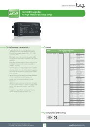
State-of-the-art operationof fluorescent lampsElectronic control gears for fluorescent lampsThe ignition and the current limitation of the gas discharge in a fluorescentlamp require a control unit connected in series. Conventionaltechnique use an iron core wound with copper wire in combinationwith a separate starter. Essential advantages are offered when usingelectronic control gears:• Cost and energy savings• Increased lighting comfort thanks to flicker-free lamp start andcalm light• Increased lamp service life and extended maintenance intervals• Safety switch-off in case of critical operating conditionsA basic distinctive feature between inductive ballasts and electroniccontrol gears (ECG) is given by the mode of lamp operation. Electroniccontrol gears typically generate high-frequency alternating voltageswith frequencies of about 30 to 150 kHz. As a result, the luminousefficacy of fluorescent lamps is increased by approx. 10% versus the50/60 Hz operation of inductive ballasts. Thus, the high-frequencyoperation allows to lower the system rating without reducing the luminousflux of the lamp. The physical reason can be seen from thecourse of the lamp voltage. When operated at mains frequency, thelamp is shortly extinguished after each mains half-wave and has to bereignited what results in the shown voltage peaks (Fig. 1a). The darkphases lead on an average to reduced luminous flux and the socalled100 Hz flickering.Energy savingsIn order to compare the power consumption and the efficiency of fluorescentlamp circuits, the system consisting of lamp + ballast has to beregarded in consideration of the achieved luminous flux of the lamp.For example, a fluorescent lamp rated as 58 W, requires system powerof up to approx. 71 W when it is operated via a conventional inductiveballast. When using electronic control gears the system rating amounts to only 55 W. Based on similar lighting levels, a lightinginstallation with conventional inductive ballasts therefore requires atleast 30% more energy than an identical lighting installation fittedwith ECG. Energy savings result as well from the reduced lamp poweras from the significantly lower power loss of an electronic control gear.Energy-Efficiency-Index EEIThe Energy-Efficiency-Index serves as a basis for an objective evaluationof the efficiency of a ballast-lamp-system. This parameter hasbeen introduced by CELMA, the Federation of National ManufacturersAssociations for Luminaires and Electrotechnical Components forLuminaires in the European Union. Per lamp type 7 categories withdifferent limiting values for the total input power are defined (Fig. 3).In order to assure a standardised classification of a given control unitinto the Energy-Efficiency-Index, measurements are based on the EuropeanNorm EN 50294 “Measurement method of total input power ofballast-lamp circuits”.The Energy-Efficiency-Index especially applies via the implementationof the European Regulation 2000/55/EC about energy efficiency requirementsas to ballasts for fluorescent lamps. This regulation aimsat provoking the changeover to efficient and energy saving systemsin view to improved climate protection. Against this background, accordingto EC-Regulation, inductive ballasts with very high power loss,classified D, are since 21.05.02 no longer allowed to be circulated. Thisapplies since 21.11.2005 as well for inductive ballasts classified C.Fig. 1aLamp voltage oscilloscope at 50 / 60 Hz operationFig. 1bLamp voltage oscilloscope at high-frequency operation ≥ 30 kHzFig. 3Energy efficiency classification using the example of a T8 58 Wfluorescent lampEEI Electronic control gear System ratingA1 Dimmable ≤ 29,5 WA2 BAT Non-dimmable (best available technology) ≤ 53,7 WA2 Non dimmable with low power loss ≤ 55 WA3 Non dimmable with increased power loss ≤ 59 WEEI Inductive control gear System ratingB1 With very low power loss ≤ 64 WB2 With low power loss ≤ 67 WC With high power loss ≤ 70 WD With very high power loss > 70 W*at 25% luminous flux20
Performance characteristicsof electronic control gearLamp preserving startIn respect of the service life of fluorescent lamps, the number ofswitch-on/switch-off cycles per day and the mode of the startingprocedure are of significant importance. An optimised start requiresappropriate preheating of the lamp electrodes. Electronic control gearsof premium quality, feature warm start procedures which lead substantiallyto an increase of lamp service life of up to 50% in comparisonto an operation with inductive ballasts.A lamp service life virtually independent of the switching frequencycan be achieved by means of a preheating which is exactly adjustedto the lamp (Fig. 4). <strong>BAG</strong> <strong>electronics</strong> ECG, e.g. of the series MLS andBCS, meet this requirement via digitally controlled starting procedures.Measurements in our laboratories have shown that more than1,000,000 switching cycles at 15 seconds intervals were not able todestroy the electrodes. A technological innovation for further optimisationof the lamp start is given by energy controlled preheating.Corresponding requirements are already constituted in regulation EN60929 regarding performance of electronic control gears, in fact in afirst step for T5 fluorescent lamps.The advantage of this procedure is that during the starting phase notonly the preheating current but also the energy being fed to the electrodeis considered. This allows a straight statement with regard tothe point in time where the optimum emission temperature has beenreached. The preheating phase is then automatically terminated. As aresult, the influence of tolerances, such as of the lamp electrodes, isbeing reduced and thus even sensible electrodes are prevented fromunnecessary loads.All electronic control gears from <strong>BAG</strong> <strong>electronics</strong> for T5 lamps markedwith the symbol of Fig. 5 already offer the optimised procedure ofenergy controlled preheating.Safety switch-off in case of abnormal lamp operationECG from <strong>BAG</strong> <strong>electronics</strong> feature automatic recognition and safetyswitch-off in case of abnormal lamp operation. This includes e.g.defective lamp electrodes or highly resistive discharging distancescaused by leaky tubes.As well, the critical operating condition at the end of service life offluorescent lamps is detected. The at that time arising rectifier effectleads to increased lamp burning voltage in the surroundings of theelectrodes and thus to raised temperature in that area. Due to thedecreased tube diameter of the T5 lamps being 16 mm, the raise intemperature is more significant than in case of T8 lamps with a diameterof 26 mm.As a consequence of the possible risk caused by thermal overload, thesafety regulation EN 61347-2-3 for electronic control gears includesthe examination of a functional End-of-Life switch-off. There are threetest methods available which of the procedure “Test 2” is known to beparticularly reliable.Electronic control gears from <strong>BAG</strong> <strong>electronics</strong>, which have been testedand approved according to the criteria required there, can be recognizedby the symbol of Fig. 6.Cut-Off technologyThe Cut-Off technology prevents permanent heating current throughthe electrodes during operation. This results in less load to the electrodesand avoids additional power loss.In combination with T5 fluorescent lamps, this circuit concept gainsadditional substantial importance. An increase in temperature in thesurroundings of the electrodes, e.g. via permanent heating, leads to aconsiderable depreciation of the luminous flux. In conjunction with thepower loss produced in addition, this may cause a drastic reduction ofthe energy efficiency of the ballast–lamp system.The Cut-Off technology is introduced for example in every ECG of theMLS range as well as in all BCS type for T5 lamps and is shown in Fig. 7.Fig. 4Optimum preheat and ignition conditions1 2 34Fig. 5Energy controlled preheatingFig. 6End-of-Life recognition “Test 2“Fig. 7Cut-Off technology21
Performance characteristicsof electronic control gearApplication in emergency lighting systemsFor use in emergency lighting systems electronic ballasts have to bedesigned for direct-current operation. Therefore ECG from <strong>BAG</strong> <strong>electronics</strong>for such applications allow longterm operation in a voltage rangefrom 198 VDC to 276 VDC. The minimum admissible battery voltagefor temporary operation is around 176 VDC. A feature that ensures aswell proper functioning until the point of time where the lighting isautomatically switched-off by means of the total discharge protectionof the battery system.ApprovalsThe approvals on the electronic control gears from <strong>BAG</strong> <strong>electronics</strong>stand for conformance with international regulations regarding safetyand operation, electromagnetic compatibility and immunity to interference:• EN 61347-1, EN 61347-2-3: General and safety requirements• EN 60929: Performance requirements• EN 61347-2-3 annex C: Special requirements for thermally protectedballasts• EN 61000-3-2: Limits for harmonic current emissions• EN 61000-3-3: Limitation of voltage fluctuations and flicker• EN 61547: EMC immunity• EN 55015: Radio disturbances < 300 MHzQuality of electronic control gearsStatements regarding the quality of electronic control gears are closelyconnected to the terms:• Service performance• Safety• Service lifeSafety means the absence of dangerous impacts on life and materialassets, in fact during normal operation and in case of failure. An importantpart of this is, e.g. that no dangerous voltage remains on thecontact pins on the fluorescent lamps, if they can be touched.Service life and thus the reliability of electronic control gears is determinedby the failure rate of their fitted components. Along withthe electrical specification and the quality of these components, thetemperature is an essential parameter. <strong>BAG</strong> <strong>electronics</strong> ECG, e.g. of theMLS and BCS series, are designed so that a failure rate of maximum2‰ per 1,000 hours may be expected if the maximum admissiblehousing temperature tc,max. which is indicated on the ECG is respected.This represents a service life of 50,000 hours at a possible failurerate of < 10%. In other terms this means that at an annual rate of2,500 operating hours a service life of 20 years will be achieved ata possible statistical failure rate of 10%. Lower temperatures withinthe electronic control gears extend their service life. If for instance thetemperature tc,max. is 10 °C lower, the failure rate is approximatelyhalved, which leads to a service life of up to 100,000 h. Analogically,in case the temperature tc,max. is exceeded this may lead to a drasticreduction in the service life.As a measure to secure the specified service life all components andcircuits of ECG from <strong>BAG</strong> <strong>electronics</strong> are designed to be operated belowtheir admissible limiting values. Moreover, in order to prevent earlyfailures caused by covert defects, all units pass various testing pointsduring the manufacturing process, i.e. amongst other things componentchecks as well as measurements of operation relevant data aremade. Before they are delivered ECG are subject to a final burn-in test.Service performance means the ability of electronic control gears tofulfil the requirements in operation to the full extent. This covers e.g.automatic switch-off in case of defective lamps, instant restart afterlamp replacement, radio interference suppression and limitation ofharmonic current emissions.Norm complicance• EN 61 347-1• EN 61 347-2-3• EN 61 347-2-3 /C• EN 60 929• EN 61 347-2-3 /J• EN 61 000-3-2• EN 61 000-3-3• EN 61 547• EN 55 015 (< 300 MHz)Markings22
Performance characteristicsof dimmable electronic control gearBy implementing dimmable electronic control gears, the user is notonly able to regulate lighting to the desired level, but is also able to decreasepower consumption by reducing the luminous flux at the sametime (Fig. 8 + 9). Dimmable electronic control gears are equipped withan additional two-pole terminal for control purposes. The analogue1–10 V interface and the digital DALI interface have established themselvesfor dimming applications in lighting technology. Both interfacesare defined in international standards to ensure component compatibility.1–10 V interfaceDimmable ECG with 1–10 V interface supply a DC control current.When connecting the ECG to a current sink, e.g. ohmic resistance, thereis a control voltage across the resistance and thus to the terminals ofthe ECG. The ECG changes the luminous flux of the operated lamp onthe basis of the applied control voltage. Control voltage can be set between1 and 10 VDC by varying the level of resistance (Fig. 8). The characteristicprofile between control voltage and luminous flux dependson the manufacturer. Instead of ohmic resistance, electronic dimmersand control units are also available on the market, which are especiallydesigned to be connected to ECG with 1–10 V interface. The maximumnumber of ECG that can be connected to a dimmer, is determined bythe dimmer‘s maximum current carrying capacity.The two-core control line for connecting to the 1–10 V interface of thedimmable ECG must be rated in any case for mains voltage. Within anelectronic control gear the dimming interface and mains power supplyare galvanically isolated from each other.DALI interfaceDALI stands for Digital Addressable Lighting Interface and describes adigital interface that was designed for room-oriented dimmable lightingapplications. The digital data transfer between a DALI controllerand the dimmable electronic control gears allows for an individualaddressing of individual luminaires and the flexible arrangement ofluminaire groups with only one common two-core control line for allluminaires. For instance, this enables to change luminaire assignmentto groups also at a later time after installation without any additionaleffort in terms of installation work. The maximum number of dimmableECG and the configurable groups within a lighting installation isdetermined by the controller that is implemented.Unlike electronic control gears with a conventional 1–10 V interface,ECG which are controlled via DALI are not only dimmed but also switchedon and off. In other words, the lighting installation is switchedpowerless. To take into account how our eyes react to illuminance, theDALI standard established the dimming characteristics for all electroniccontrol gears as a logarithmic profile (Fig. 9).The two-core control line for connecting to the DALI interface of thedimmable ECG must be rated in any case for mains voltage. At thesame time, the DALI standard allows for joint routing of the mainscable and the control line in a sheathed cable. Within an electroniccontrol gear the dimming interface and mains power supply are galvanicallyisolated from each other.Push-Dim – Dimming and switching via push buttonFor a wide variety of dimmable lighting systems, a standard pushbuttonis sufficient for switching and dimming (Fig. 11). The dimmableelectronic control gears from <strong>BAG</strong> <strong>electronics</strong> with Push-Dim functionare designed for this in addition to the DALI or 1–10 V interface withadditional input for the alternative installation of a push-button. Thepush-button may be connected optionally between the phase or neutralconductor of the mains voltage supply of the ECG and the pushbuttoninput of the ECG unit. The 1–10 V and DALI interface and pushbuttonmust not be used simultaneously.Fig. 8 1–10 V profilesLuminous Lichtstrom/Systemleistung flux/system rating [%] [%]1008060402000Lichtstrom Luminous flux Systemleistungrating2 4 6Control Steuerspannung voltage [VDC]810Fig. 9 DALI profilesLichtstrom/Systemleistung Luminous flux/system rating [%] [%]1008060402000Lichtstrom Luminous flux Systemleistungrating50 100 150 200DALI-Wert value250Fig. 10 Comparison 1–10 V interface/DALIFig. 11 Push button operationWiringAddressabilityof ECG1-10V DALITwo-core control line,observe polarityNoNorm IEC 60 929 IEC 62 386* max. 64 according to standardTwo-core control line,no polarity error possibleYesMax. number of Depends on dimmer or Depends onECGECG installeddimmer or ECGinstalled *Switch / dim Separate functions Combined functionsDim profile Specified byStandardised,manufacturer logarithmicShort push< 0,5 s Lamp ON*Lamp OFF(stand-by operation)at last dimming level (memory function)*Lamp ON(lamp operation)Lamp offLong push> 0,5 s Lamp ON and dim Dim up or downLong push(≥ 10 s)- Synchronisation mode:lamp = 100% luminous fluxFig. 12 Push-Dim functionality23
Electronic control gear within Multi-Lamp technologyThe generation of Multi-Lamp ECG was developed by <strong>BAG</strong> as a resultof continued technological progress in electronic control gear. Theyfeature an automatic recognition of the connected lamp and are independentlyable to adjust their operation parameters exactly to therespective lamp. The major difference in contrast to the conventionalMultipower technique is its ability to operate lamps with significantlydiffering electrical data. The figure (Fig. 13) emphasises this, illustratedby the operating of T5-lamps.An electronic control gear can be considered as a constant currentsource. As all lamps of the T5-FH-series need identical lamp current,in general only one single ECG version is sufficient for their operation.Thus, lamps of different wattages can be connected to the sameECG what explains the term of Multipower technique. The Multi-LampECG offers the extra option of operating all further lamps of the FQseriesat their standardised data. After lamp recognition the requiredoperation current is automatically adjusted. In addition, all necessaryadjustments are made, e.g. to realise an optimum lamp start anda safe recognition of an abnormal lamp operation. This results in asubstantial advantage especially for T5-lamps being available in thesame length but with different wattages (Fig. 14). This means that, e.g.a luminaire with a T5 35 W-lamp can alternatively be fitted at anytime with a lamp in T5 49 W- or T5 80 W-version in order to achievea different luminous flux. The replacement of the lamp will be recognisedautomatically and after lamp detection all parameters will beadjusted. The number of necessary versions of T5 luminaires is thussignificantly reduced whereas at the same time a flexible solution isoffered to the user.24
Automatic lamp recognition – non-dimmable Multi-Lamp versionsIn case of non-dimmable versions of the Multi-Lamp the automaticlamp recognition takes place in several steps. It is basically startedwith the first switch-on of the mains voltage supply on the initialstart-up of the lighting installation (Fig. 15). The same applies in caseof replacing T5-lamps of identical length and different wattages.For the purpose of a well-defined detection of the lamp differentmeasuring data are taken by the ECG and analysed by a micro-controller.During the preheating phase firstly the impedance of the electrodesis measured. Subsequently, the lamp is ignited and operatedwith a test current. After a period of approx. 5 minutes the resultinglamp voltage is detected. The cumulated values will now serve to identifythe exact lamp type and power. Afterwards, all operation data areadjusted and the result is stored. Any new start takes place on thebasis of the actual values. A lamp recognition being conducted in thisway not only allows for distinguishing lamps of similar length, but allT5 lamps in the range between 14 W and 80 W.Automatic lamp recognition – dimmable Multi-Lamp versionsThe steps of automatic lamp recognition for the dimmable Multi-Lampcontrol gears is for the most part almost identical to the process fornon-dimmable versions. However, in order to offer to the user the optionof individual light level setting directly after installation the step oflamp operation with constant test current is omitted (Fig. 15). The typeof lamp and the wattage class are determined directly based on theselection of the lamp electrodes during the preheating phase.Lamp recognition in this form still ensures the differentiation of T5lamps of the same length, but of different wattages. Using T5 lampsof other lengths does require a different Multi-Lamp ECG respectively.Fig. 13Operating points of T5 lampsFig. 14T5 lamps of the same length250T5 FHT5 FQHEHOLengthLampenspannung voltage [V] [V]2001501005035 W28 W21 W14 W49 W24 W39 W 54 W80 W14 W 24 W 549 mm21 W 39 W 849 mm28 W 54 W 1149 mm00100200 300 400 500 600Lampenstrom current [mA]35 W 49 W 80 W 1449 mmFig. 15Lamp recognition processStart upPreheat phase:identify lampelectrodeLamp operationwith test currentMeasure lampvoltageSave lampdataAdjustoperatingdata of ECGDefine lamptype andwattage*not for dimmable versions25
Non dimmable electronic control gearfor T5 and TC-L/F in Multi-Lamp technologyPerformance characteristics• Multi-Lamp technology for automatic lamp recognition and optimumoperation of T5 and TC-L/F lamps• Twingle operation with 1 or 2 lamps• Luminaire can be fitted with different lamps (e.g. T5: 35W, 49W, 80W)• Compact housing in slim design for space-saving application in luminaires• Energy-controlled electrode preserving lamp warm start for maximumlamp life irrespective of switching frequency starting time < 1 s• Cut-Off technology: minimised heat current through electrodes duringoperation, for optimum light output and reduced power loss.• Automatic restart after lamp replacement• Safety switch-off in case of abnormal lamp operation, e. g. defectiveelectrode and end of lamp life tested acc. to EN 61347-2-3 + Test 2• Constant lamp output independent of mains voltage fluctuations• Optimum ignition safety even at low temperatures: automatic second startif necessary• Automatic restart after lamp replacement• Suitable for direct current operation and emergency lighting installationscomplies with requirements for emergency lighting according to EN 61347-2-3/• Quick restart of lamps after short power disruptions• Connecting earth can be disregarded in suitable luminaires with safetyclassification 2• Energy efficiency EEI A2/A2BAT• Nominal service life: 50.000 h with failure rate of ≤ 10% and operation att c t c,max for: 10092026 and 1001609A2 BATTechnical dataGeneral technical dataMains power supplyated voltage range220 240 reuency0, 50 Hz ... 60 HzMax. admissible voltage range (continuous) 19 264 Battery operationoltage range for continuous operation19 DC 27 DCLowest value for temporary operation 176 DC 1)Overvoltage protection350 VAC / 2 hLeakage current< 0,5 mA / ECG1)eliable lamp ignition only >19Standards complicance• EN 61 347-1• EN 61 347-2-3• EN 61 347-2-3 /C• EN 60 929Markings74 110 9• EN 61 000-3-2• EN 61 000-3-3• EN 61 5• EN 55 015 (< 300 MHz)Wiring diagrams31234231 12 2334456 57 6123One-lamp operation41-lampiger Betrieb56* eep wires short. efer to wiring specifications in data sheets.26
Operating dataa 6 b 4Model Order No. Lamp System Input Operating Power Lamp Wiring Approvalsrating current* frequency factor power diagramW A kHz WMLS0.1-11/220-240 10071608 1x T5 2 32 0,15 90 0,97 2 3 a, b1x T5 35 39 0,1 90 0,97 35 3 a, b1x T5 49 53,5 0,24 75 0,97 49 3 a, b1x T5 54 60 0,27 42 0,97 54 3 a, b1x T5 0 6 0,37 41 0,97 0 3 a, bMLS39.1-2-11/220-20 10092026 1/2x T5 14 1/33 0,08/0,15 98/86 0,85/0,93 1/28 23 a, b1/2x T5 21 24,5/4 0,11/0,2 92/82 0,9/0,9 21/2 23 a, b1/2x T5 24 28/5 0,12/0,23 6/66 0,92/0,9 2/8 23 a, b1/2x T5 39 2/82 0,1/0,35 6/66 0,96/0,98 39/8 23 a, b1/2x TC-L/ 1 19/35,5 0,09/0,15 66/6 0,9/0,9 16/32 23 a, b1/2x TC-L/ 24 2/50 0,12/0,23 6 0,92/0,9 22/ 23 a, b1/2x TC-L/ 36 3,5/69 0,1/0,29 6 0,9/0,98 32/6 23 a, b1/2x TC-L 40 3,5/88 0,2/0,38 6 0,96/0,99 0/80 23 a, bMLS0.1/54.2-11/220-240 10071609 1/2 x T5 2 32/6 0,15/0,28 6/63 0,93/0,98 28/5 23 a, b1/2 x T5 35 39/80 0,18/0,35 66/62 00,95/0,99 35/3 23 a, b1/2 x T5 49 55/10 0,2/0,5 5/59 0,9/0,99 51/98 23 a, b1/2 x T5 54 60/113 0,26/0,8 0,98/0,99 55/10 23 a, b1x T5 0 86 0,36 6 0,99 9 23 a, b at mains= 230 ACDimensions | Weights | Temperatures1/2xTC-L 55 56/105 0,25/0,3 0,98/0,99 52/98 23 a, bIT5T5CT8TC-DELTC-TELTC-SETC-LTC-FTC-DDHI /HI-CEModelXmmX MmmYmmZmmMLS0.1-11/220-240 280 265 30 21 8,5 B, I 0,23 25 C ... 55 C 70 CMLS39.1-2-11/220-240 20 265 30 21 ,5 B, I 0,21 25 C ... 55 C 75 CMLS0.1/54.2-11/220-240 20 265 30 21 ,5 B, I 0,2 25 C ... 55 C 75 CZ MmmSketchWeightkgAmbient (t a)° CHousing (t c)° CHousing diagramBZMY ZX MX27
Dimmable electronic control gearfor T5 lamps in Multi-Lamp technologyPerformance characteristics• Dimmable ECG in Multi-Lamp technology with automatic lamp recognitionfor optimum operation of T5 lamps• Luminaire can be fitted with different lamps (e.g. T5: 35W, 49W, 80W)• Dim interface: DALI or 1–10 V• Push-Dim: dim and switch with push button with memory function• Dimming range 1...100% luminous flux• Energy-controlled electrode preserving lamp warm start for maximumlamp life irrespective of switching frequency starting time < 1 s• Cut-Off technology at 100% luminous flux: minimised heat current throughelectrodes during operation, for optimum light output and reduced powerloss• Safety switch-off in case of abnormal lamp operation, e. g. defectiveelectrode and end of lamp life tested acc. to EN 61347-2-3 + Test 2• Automatic restart after lamp replacement• Suitable for direct current operation and emergency lighting installationscomplies with requirements for emergency lighting according to EN 61347-2-3/• Quick restart of lamps after short power disruptions• Energy efficiency EEI A1/A1BAT• Nominal service life: 50.000 h with failure rate of ≤ 10% and operation att c t c,maxTechnical dataStandards complianceGeneral technical dataMains power supplyNominal voltage rangereuency22020 AC0, 50 Hz ... 60 Hz• EN 61 347-1• EN 61 347-2-3• EN 61 347-2-3 annex C• EN 60 929• EN 61 000-3-2• EN 61 000-3-3• EN 61 5• EN 55 015 (< 300 MHz)• EN 62 386Max. voltage range (constant operation)198– 264 VACBattery operationoltage range for continuous operation /lamp startMinimum value fortemporary operation19826 DC16 DCDim interfacesOvervoltage protectionMains input current350 AC/2hDim interface DALI26 ACDim interface 110 ush button interface26 AC26 ACMarkingsStand-by power DALI/push button operationControl current 1–10 V interfaceLeakage current1)eliable lamp ignition only >19≤ 0.5 W≤ 0.6 mA< 0.5 mA / ECG74 110 9Wiring diagram60DADA123461 12341−10 V99 123DADAPush-DIMLN4567* eep wires short. efer to wiring specifications in data sheets.28
Operating dataModel Order-No. Lamp SystemratingIa 6 b 4MLD5.1-01/220-20/DALI 167192 1 x T5 28 32 0,15 85...150 0,96 28 60 a,b1 x T5 5 60 0,2 5...120 0,96 5 60 a,bMLD80.1-01/220-20/110 166102 1 x T5 35 38 0,1 90...150 0,9 35 61 a,b1 x T5 9 53 0,2 80...150 0,9 9 61 a,b1 x T5 80 88 0,39 5...120 0,98 80 61 a,bMLD80.1-01/220-20/DALI 166672 1 x T5 35 38 0,1 90...150 0,9 35 61 a,b1 x T5 9 53 0,2 80...150 0,9 9 61 a,b1 x T5 80 88 0,39 5...120 0,98 80 61 a,bMLD39.2-11/220-20/DALI 10092117 2 x T5 1 33 0,15 69...120 0,9 28 99 a,b2 x T5 21 5 0,20 2...120 0,9 2 99 a,b2 x T5 2 9 0,22 0...120 0,9 8 99 a,b2 x T5 39 9 0,35 0...120 0,99 8 99 a,bMLD5.2-11/220-20/ DALI 10092121 2 x T5 28 63 0,28 0...120 0,98 5 99 a,b at mains= 230 ACDimensions | Weights | TemperaturesInputcurrent*OperatingfrequencyPowerfactorLamppowerW A kHz WWiringdiagramIIIApprovals2 x T5 35 8 0,3 0...120 0,99 3 99 a,b2 x T5 9 10 0,5 0...120 0,99 98 99 a,b2 x T5 5 115 0,51 0...120 0,99 10 99 a,bT5ModelXmmX MmmYmmZmmMLD5.1-01/220-20/DALI 360 350 30 21 10,5 B,I 0,28 10 C ... 60 C 75 CMLD80.1-01/220-20/110 360 350 30 21 10,5 B,I 0,28 10 C ... 60 C 75 CMLD80.1-01/220-20/DALI 360 350 30 21 10,5 B,I 0,28 10 C ... 60 C 75 CMLD39.2-11/220-20/DALI 360 350 30 21 9 M,III 0,28 5 C ... 55 C 75 CMLD5.2-11/220-20/DALI 360 350 30 21 9 M,III 0,32 5 C ... 55 C 75 CZ MmmSketchWeightkgAmbient(t a)Housing(t c)Housing diagramBZMY ZMZMY ZX MXX MX29
Non dimmable electronic control gearfor T5 and TC-L/F fluorescent lampsPerformance characteristics• Short housing in flat design for space-saving application in luminaires• Multipower - Technology for operation with different lamps on the samecontrol gear• Energy controlled, electrode preserving lamp warm start for maximum lamplife irrespective of switching frequency starting time < 1,5 s• Cut-Off technology: minimised heat current through electrodes duringoperation, for optimum light output and reduced power loss.• Safety switch-off in case of abnormal lamp operation, e. g. defectiveelectrode and end of lamp life tested acc. to EN 61347-2-3 + Test 2• Flimmer free light through high frequency lamp operation, no stroboscopeeffect• Constant lamp output independent of mains voltage fluctuations• Optimum ignition safety even at low temperatures: automatic second startif necessary• Automatic restart after lamp replacement• Suitable for direct current operation and emergency lighting installationscomplies with requirements for emergency lighting according to EN 61347-2-3/• Quick restart of lamps after short power disruptions• Connecting earth can be disregarded in suitable luminaires with safetyclassification 2• Energy efficiency EEI A2/A2BAT• Extended nominal service life:75.000 h at t c t c,max with failure rate of ≤ 10%100.000 h operation at t c t c,max -10 with failure rate ≤ 10 %A2 BATQ-TESTEDTechnical dataGeneral technical dataMains power supplyated voltage range220 240 reuency0, 50 Hz ... 60 HzMax. admissable voltage range (continuous) V – VBattery operationoltage range for continuous operation19 DC 27 DCLowest value for temporary operation 176 DC 1)Overvoltage protection350 VAC / 2 hLeakage current< 0,5 mA / ECG1)eliable lamp ignition only >19Standards complicance• EN 61 347-1• EN 61 347-2-3• EN 61 347-2-3 annex C• EN 60 929Markings74 110 9• EN 61 000-3-2• EN 61 000-3-3• EN 61 5• EN 55 015 (< 300 MHz)Wiring diagrams32312341234561 12 23 34 41 12 23 34 45 56 61278910105212345 1 16 2 27 78 89 910 101 12 23 34 45 56 61278910105312345 1 16 2 27 78 89 910 101 12 23 34 45 56 6* eep wires short. efer to wiring specifications in data sheets.30121 12 2
Operating dataModel Order-No. Lamp SystemratingBZMY ZInputcurrent*Operatingfrequencya 6 b 4W A kHz WCS14.3-4-01/220-240 10052868 3 T5 14 47 0,22 50 0,96 41 52 a, b4 T5 14 59 0,26 50 0,96 55 53 a, bCS35.1-11/220-240 10077579 1 T5 14 17 0,0 4 0,93 14 3 a, b1 T5 21 24 0,10 4 0,96 21 3 a, b1 T5 2 31 0,14 4 0,9 2 3 a, b1 T5 35 39 0,17 4 0,99 35 3 a, bCS35.2-11/220-240 10077580 2 T5 14 31 0,15 51 0,97 2 23 a, b2 T5 21 47 0,21 51 0,97 42 23 a, b2 T5 2 64 0,2 51 0,97 56 23 a, b2 T5 35 74 0,34 51 0,97 70 23 a, bCS39.1-11/220-240 10077581 1 T5 24 27 0,12 44 0,9 23 3 a, b1 T5 39 41 0,1 44 0,97 3 3 a, b1 TC-L/- 1 19 0,0 44 0,96 16 3 a, b1 TC-L/- 24 26 0,12 44 0,9 22 3 a, b1 TC-L/- 36 37 0,16 44 0,99 32 3 a, b1 TC-L 40 41 0,1 44 0,99 40 3 a, bCS39.2-11/220-240 10077582 2 T5 24 53 0,24 42 0,9 46 23 a, b2 T5 39 2 0,35 42 0,99 6 23 a, b2 TC-L/- 1 34 0,15 42 0,96 2 23 a, b2 TC-L/- 24 50 0,23 42 0,9 44 23 a, b2 TC-L/- 36 67 0,29 42 0,99 60 23 a, b2 TC-L 40 6 0,35 42 0,99 0 23 a, bCS49.1-11/220-240 10077583 1 T5 49 54 0,23 52 0,99 49 3 a, bCS49.2-11/220-240 2 T5 49 109 0,4 52 0,99 9 23 a, bCS54.1-11/220-240 10077585 1 T5 54 59 0,26 45 0,99 54 3 a, b1 TC-L 55 60 0,26 45 0,99 55 3 a, b1 T 5 55 0,25 45 0,99 50 3 a, bCS54.2-11/220-240 10077586 2 T5 54 107 0,47 46 0,99 96 23 a, b2 TC-L 55 10 0,47 46 0,99 97 23 a, bCS0.1-11/220-240 10077587 1 T5 0 7 0,3 47 0,99 0 3 a, b1 TC-L 0 7 0,3 47 0,99 0 3 a, bSCS0.2-01/220-240 166692 2 x T5 0 173 0,76 47 0,99 0 23 a, b2 x TC-L 0 16 0,74 47 0,99 0 23 a, b at mains= 230 ACI IVDimensions | Weights | TemperaturesModelPowerfactorLamppowerWiringdiagramCS14.3-4-01/220-240 280 20 2 21 9 B, IV 0,25 20 C ... 60 C 70 CCS35.1-11/220-240 280 265 30 21 9 B, IV 0,18 20 C ... 60 C 75CCS35.2-11/220-240 280 265 30 21 9 B, IV 0,20 20 C ... 55 C 70CCS39.1-11/220-240 280 265 30 21 9 B, IV 0,18 20 C ... 60 C 75CCS39.2-11/220-240 280 265 30 21 9 B, IV 0,20 20 C ... 55 C 75CCS49.1-11/220-240 280 265 30 21 9 B, IV 0,18 20 C ... 60 C 70CCS49.2-11/220-240 280 265 30 21 9 B, IV 0,20 20 C ... 55 C 75CCS54.1-11/220-240 280 265 30 21 9 B, IV 0,19 20 C ... 60 C 75CCS54.2-11/220-240 280 265 30 21 9 B, IV 0,20 20 C ... 55 C 0CCS0.1-11/220-240 280 265 30 21 9 B, IV 0,20 20 C ... 55 C 75CSCS0.2-01/220-240 25 15 30 21 10.5 B, I 0,35 25 C ... 55 C 75CHousing diagramsXmmX MmmYmmZmmZ MmmSketchWeightkgAmbient(t a)Housing(t c)ApprovalsT5TC-LTC-FX MX31
Non dimmable electronic control gearfor T5 lamps in slim housingPerformance characteristics• Compact housing in slim design for space-saving application in luminaires:housing width of only 24 mm• Lamp terminals at both ends of the ECG for simplified wiring and improvedEMC• Multipower - Technology for operation with different lamps on the samecontrol gear• Energy controlled, electrode preserving lamp warm start for maximum lamplife irrespective of switching frequency starting time < 1 s• Cut-Off technology: minimised heat current through electrodes duringoperation, for optimum light output and reduced power loss• Safety switch-off in case of abnormal lamp operation, e. g. defectiveelectrode and end of lamp life tested acc. to EN 61347-2-3 + Test 2• Automatic restart after lamp replacement• Constant light output irrespective of mains power fluctuation• Suitable for direct current operation and emergency lighting installationscomplies with requirements for emergency lighting according to EN 61347-2-3/• Energy efficiency EEI A2• Nominal service life: 50.000 h with a failure rate of ≤ 10% and operationat t c t c,maxTechnical dataStandards complicanceGeneral technical dataMains power supplyated voltage range220 240 reuency0, 50 Hz ... 60 HzMax. admissible voltage range (continuous) V – VBattery operationoltage range for continuous operation VDC – VDCLowest value for temporary operation 176 VDC )Overvoltage protection350 VAC / 2 hLeakage current< 0,5 mA / ECG1)eliable lamp ignition only >19• EN 61 347-1• EN 61 347-2-3• EN 61 347-2-3 annex C• EN 60 929Markings7 110 9• EN 61 000-3-2• EN 61 000-3-3• EN 61 5• EN 55 015 (< 300 MHz)Wiring diagrams1412 34* eep wires short. efer to wiring specifications in data sheets.32
Operating dataModel Order-No. Lamp SystemratingW A kHz WCS35.1N-01/220-240 1 x T5 21 23 0.10 47 0.95 21 14 a1 x T5 28 31 0.1 0.95 28 1 a1 x T5 35 38 0.1 0.95 35 1 aCS39.1N-01/220-20 10097786 1 x T5 2 2 0.12 0.98 2 1 a1 x T5 39 2 0.19 0.98 39 1 aCS9.1N-01/220-20 10097787 1 x T5 9 5 0.2 51 0.98 9 1 aCS5.1N-01/220-20 10097788 1 x T5 5 59 0.26 52 0.98 5 1 aCS80.1N-01/220-20 10097789 1 x T5 80 8 0.38 0.98 80 1 a at Netz= 230 ACInputcurrent*OperatingfrequencyPowerfactorLamppowerWiringdiagrama 6ApprovalsT5Dimensions | Weights | TemperaturesIIModelXmmX MmmYmmZmmCS35.1N-01/220-240 300 290 24 21 — N, II 0,20 20 C ... 60 C 70CCS39.1N-01/220-240 300 290 24 21 — N, II 0,20 20 C ... 60 C 70CCS49.1N-01/220-240 300 290 24 21 — N, II 0,20 20 C ... 60 C 70CCS54.1N-01/220-240 300 290 24 21 — N, II 0,21 20 C ... 60 C 70CCS0.1N-01/220-240 300 290 24 21 — N, II 0,21 20 C ... 60 C 70CZ MmmSketchWeightkgAmbient(t a)Housing(t c)Housing diagramsNY ZX MX33
Operating dataModel Order No. Lamp SystemratingW A kHz WCD35.1-01/220-20/1-10 10097244 1 x T5 1 18 0.08 50...85 0.96 1 6 a1 x T5 21 25 0.12 50...85 0.96 21 6 a1 x T5 2 32 0.15 50...85 0.96 28 6 a1 x T5 35 39 0.19 50...85 0.96 35 6 aCD39.1-01/220-20/1-10 10097246 1 x T5 2 26 0.12 5...105 0.98 2 6 a1 x T5 39 38,5 0.1 5...105 0.98 39 6 aCD9.1-01/220-20/1-10 10097247 1 x T5 9 55 0.2 55...80 0.9 9 6 aCD5.1-01/220-20/1-10 10097248 1 x T5 5 58 0.26 55...120 0.9 5 6 aCD80.1-01/220-20/1-10 10097249 1 x T5 80 86 0.3 5...115 0.98 80 6 a1 x TC-L 80 86 0.37 5...115 0.98 80 6 aCD35.2-01/220-20/1-10 10097294 2 x T5 1 3 0.15 5...90 0.9 1 a2 x T5 21 8 0.21 5...90 0.9 21 a2 x T5 28 6 0.28 5...90 0.9 28 a2 x T5 35 8 0.35 5...90 0.9 35 aCD39.2-01/220-20/1-10 10097296 2 x T5 2 53 0.23 0...110 0.9 2 a2 x T5 39 8 0.3 0...110 0.9 39 aCD9.2-01/220-20/1-10 10097297 2 x T5 9 106 0. 50...90 0.98 9 aCD5.2-01/220-20/1-10 10097298 2 x T5 5 115 0.51 0...15 0.9 5 aCD80.2-01/220-20/1-10 10097299 2 x T5 80 12 0.5 5...120 0.9 80 a2 x TC-L 80 12 0.5 5...120 0.9 80 aCD1.3-01/220-20/1-10 10097281 3 x T5 1 50 0.22 56...66 0.95 1 6 aCD1.-01/220-20/1-10 10097291 x T5 1 66 0.29 8...80 0.95 1 5 a at mains= 230 ACInputcurrent*OperatingfrequencyPowerfactorLamppowerWiringdiagrama 6ApprovalsT5Dimensions | Weights | TemperaturesIIIModelXmmX MmmYmmZmmCD35.1-01/220-20/1-10 360 350 30 21 9 M, III 0,26 5 C ... 55 C 75CCD39.1-01/220-20/1-10 360 350 30 21 9 M, III 0,25 5 C ... 55 C 70CCD9.1-01/220-20/1-10 360 350 30 21 9 M, III 0,26 5 C ... 55 C 70CCD5.1-01/220-20/1-10 360 350 30 21 9 M, III 0,26 5 C ... 55 C 70CCD80.1-01/220-20/1-10 360 350 30 21 9 M, III 0,26 5 C ... 55 C 70CCD35.2-01/220-20/1-10 425 415 30 21 9 M, III 0,33 5 C ... 55 C 75CCD39.2-01/220-20/1-10 425 415 30 21 9 M, III 0,33 5 C ... 55 C 70CCD9.2-01/220-20/1-10 425 415 30 21 9 M, III 0,36 5 C ... 55 C 70CCD5.2-01/220-20/1-10 425 415 30 21 9 M, III 0,33 5 C ... 55 C 75CCD80.2-01/220-20/1-10 425 415 30 21 9 M, III 0,39 5 C ... 55 C 75CCD1.3-01/220-20/1-10 360 350 39 21 9 M, III 0,32 5 C ... 60 C 75CCD1.-01/220-20/1-10 360 350 39 21 9 M, III 0,32 5 C ... 60 C 75CHousing diagramsZ MmmSketchWeightkgAmbient(t a)Housing(t c)MZMY ZX MX35
Non dimmable electronic control gearfor T8 lampsPerformance characteristics• Short housing in flat design for space-saving application in luminaires• Energy controlled, electrode preserving lamp warm start for maximum lamplife irrespective of switching frequency starting time < 1,5 s• Cut-Off technology: minimised heat current through electrodes duringoperation, for optimum light output and reduced power loss.• Safety switch-off in case of abnormal lamp operation, e. g. defectiveelectrode and end of lamp life tested acc. to EN 61347-2-3 + Test 2• Flimmer free light through high frequency lamp operation, no stroboscopeeffect• Constant lamp output independent of mains voltage fluctuations• Optimum ignition safety even at low temperatures: automatic second startif necessary• Automatic restart after lamp replacement• Suitable for direct current operation and emergency lighting installationscomplies with requirements for emergency lighting according to EN 61347-2-3/• Constant light output irrespective of mains power fluctuation• Quick restart of lamps after short power disruptions• Connecting earth can be disregarded in suitable luminaires with protectionclass 2• Energy efficiency EEI A2BAT• Extended nominal service life:75.000 h at t c t c, max with failure rate of ≤ 10%100.000 h operation at t c t c, max -10 with failure rate ≤ 10 % For BCS.F lifetime at tctc,max . h, . h at tc,max-A2 BATQ-TESTEDTechnical dataGeneral technical dataMains power supplyated voltage range220 240 reuency0, 50 Hz ... 60 HzMax. admissible voltage range (continuous) V – VBattery operationoltage range for continuous operation19 DC 27 DCLowest value for temporary operation 176 DC 1)Overvoltage protection350 VAC / 2 hLeakage current< 0,5 mA / ECG1)eliable lamp ignition only >19Standards complicance• EN 61 347-1• EN 61 347-2-3• EN 61 347-2-3 annex C• EN 60 929Markings7 4 110 9• EN 61 000-3-2• EN 61 000-3-3• EN 61 5• EN 55 015 (< 300 MHz)Wiring diagrams13 122343423112234345566* eep wires short. efer to wiring specifications in data sheets.11227788910 91050 511122343455667891012345611227788910 910112234345566567891012345636
BCDDimmable electronic control gearfor T8- and TC-L/F lampsPerformance characteristics• Dimming interface: 1–10 V• Dimming range 1...100% luminous flux• Multi-Power technology for operation of different lamps and wattages onthe same ECG• Electrode preserving warm start for maximum lamp life, even at increasedswitching frequency starting time < 1.5 s• Cut-Off technology at 100% luminous flux: minimised heat current throughelectrodes during operation, for optimum light output and reduced powerloss.• Automatic restart after lamp replacement• Safety switch-off in case of abnormal lamp operation, e. g. defectiveelectrode and end of lamp life tested acc. to EN 61347-2-3• Suitable for direct current operation and emergency lighting installationscomplies with requirements for emergency lighting according to EN 61347-2-3/• Energie efficiency EEIA1• Nominal service life: 50.000 h with failure rate of ≤ 10% and operation att c t c,maxTechnical dataStandards complianceGeneral technical dataMains power supplyated voltage range220 240 reuency0, 50 Hz ... 60 HzMax. admissible voltage range (continuous) V – VBattery operationoltage range for continuous operation19 DC 27 DCLowest value for temporary operation 176 DC 1)Overvoltage protection350 VAC / 2 hLeakage current< 0,5 mA / ECG1-10V control current 0,2 mA1)eliable lamp ignition only >19• EN 61 347-1• EN 61 347-2-3• EN 61 347-2-3 annex C• EN 60 929Dim interfaceMarkings7 110 9• EN 61 000-3-2• EN 61 000-3-3• EN 61 5• EN 55 015 (< 300 MHz)Wiring diagrams64 12341−10 V74 1234561−10 V77617161514n.c.+ 1-10V–12345677717161514n.c.+ 1-10V–1234567*eep wires short. efer to wiring specifications in data sheets.EVG_Anschlussbild_76_BCD_1-10V_3lampig.epsEVG_Anschlussbild_77_BCD_1-10V_4lampig.eps38
Operating dataModel Order No. Lamp SystemratingInputcurrent*OperatingfrequencyPowerfactorLamppowerWiringdiagramW A kHz WCD18.1-01/220-20/1-10 10097143 1 x T8 18 19 0.09 50...100 0.96 16 6 a1 x T8 30 30 0.13 50...100 0.96 26 6 -CD36.1-01/220-20/1-10 10097144 1 x T8 36 36 0.16 5...90 0.98 32 6 a1 x T8 18 36 0.16 5...90 0.98 32 6 a1 x TC-L 0 6 0.21 5...90 0.98 2 6 aCD58.1F-01/220-20/1-10 10097145 1 x T8 58 5 0.25 50...110 0.9 50 6 aCD18.2-01/220-20/1-10 10097193 2 x T8 18 39 0.1 5...10 0.9 16 a2 x T8 30 58 0.26 5...10 0.9 26 -CD36.2-01/220-20/1-10 10097194 2 x T8 36 0.31 0...110 0.9 32 a2 x TC-L/-36 0.31 0...110 0.9 32 a2 x TC-L 0 89 0.38 0...110 0.9 0 aCD58.2-01/220-20/1-10 10097195 2 x T8 58 110 0.8 0...15 0.9 50 aCD55.1-01/220-20/1-10 10097079 1 x TC-L 55 59 0.2 5...120 0.98 55 6 aCD55.2-01/220-20/1-10 10097089 2 x TC-L 55 122 0.5 50...10 0.98 55 aCD18.3--01/220-20/1-10 10097171 3 x T5 2 6 0.33 ...5 0.95 2 6 a3 x T8 18 5 0.25 ...5 0.95 16 6 a3 x TC-L 18 5 0.25 ...5 0.95 16 6 a x T8 18 0.32 ...5 0.95 16 a x TC-L 18 0.32 ...5 0.95 16 a at Netz= 230 ACa 7ApprovalsT5T8TC-LTC-FDimensions | Weights | TemperaturesIIIModelXmmX MmmYmmZmmCD18.1-01/220-20/1-10 360 350 30 21 9 M, III 0,25 5 C ... 55 C 70CCD36.1-01/220-20/1-10 360 350 30 21 9 M, III 0,25 5 C ... 55 C 70CCD58.1-01220-20/1-10 360 350 30 21 9 M, III 0,26 5 C ... 55 C 70CCD18.2-01/220-20/1-10 425 415 30 21 9 M, III 0,33 5 C ... 55 C 70CCD36.2-01/220-20/1-10 425 415 30 21 9 M, III 0,33 5 C ... 55 C 75CCD58.2-01/220-20/1-10 425 415 30 21 9 M, III 0,33 5 C ... 55 C 75CCD55.1-01/220-20/1-10 360 350 30 21 9 M, III 0,26 5 C ... 55 C 70CCD55.2-01/220-20/1-10 425 415 30 21 9 M, III 0,35 5 C ... 55 C 70CCD18.3--01/220-20/1-10 360 350 39 21 9 M, III 0,31 5 C ... 60 C 75CZ MmmSketchWeightkgAmbient(t a)Housing(t c)Housing diagramsMZMY ZX MX39
Non dimmable electronic control gearfor CFL, T5 and T8 lampsPerformance characteristics• All models in compact housing for space-saving application in luminaires• Multi-Power technology for operation of different lamps and wattages onthe same ECG• Electrode preserving warm start for maximum lamp life, even at increasedswitching frequency starting time < 1.5 s• Cut-Off technology: minimised heat current through electrodes duringoperation, for optimum light output and reduced power loss.• Safety switch-off in case of abnormal lamp operation, e. g. defectiveelectrode and end of lamp life tested acc. to EN 61347-2-3 + Test 2• Suitable for direct current operation and emergency lighting installationscomplies with requirements for emergency lighting according to EN 61347-2-3/• Constant lamp output independent of mains voltage fluctuations• Optimum ignition safety even at low temperatures: automatic second startif necessary• Automatic restart after lamp replacement• Suitable for direct current operation and emergency lighting installationscomplies with requirements for emergency lighting according to EN 61347-2-3/• Quick restart of lamps after short power disruptions• Connecting earth can be disregarded in suitable luminaires with safetyclassification 2• Energy efficiency EEIA2• Nominal service life: 50.000 h with failure rate of ≤ 10% and operation att c t c,maxTechnical dataSpecial model SCS42.1Q-01/220-240/4kV:• Enhanced voltage safety in case of symmetrical and asymmetrical voltageimpulse of up to 4 kV• Designed e.g. for application in outdoor luminairesStandards complianceGeneral technical dataMains power supplyated voltage range220 240 reuency0, 50 Hz ... 60 HzMax. admissible voltage range (continuous) V – VBattery operationoltage range for continuous operation19 DC 27 DCLowest value for temporary operation 176 DC 1)Overvoltage protection350 VAC / 2 hLeakage current< 0,5 mA / ECG1)eliable lamp ignition only >19• EN 61 347-1• EN 61 347-2-3• EN 61 347-2-3 annex C• EN 60 929Markings7 41109• EN 61 000-3-2• EN 61 000-3-3• EN 61 5• EN 55 015 (< 300 MHz)Wiring diagrams111234* eep wires short. efer to wiring specifications in data sheets.40
Operating dataModel Order No. Lamp Systemratinga 7 bW A kHz WCS17.1-2-01/220-240 1/2x TC-HE 14 17/32 0,0/0,15 50 0,9 14 31 a1/2x TC-HE 17 20/3 0,10/0,17 50 0,9 17 31 aCS1.1-2-01/220-240 1/2x TC-DEL/-TEL 1 19/37 0,0/0,17 41 0,95 16 31 a, bCS21.1-2-01/220-240 1/2x T5 14 15/2 0,07/0,13 50 0,90 14 31 -1x T5 21 22 0,10 50 0,90 21 31 -1/2x TC-DD 10 12/21 0,05/0,10 50 0,90 10 31 -1/2x TC-DD 16 17/29 0,07/0,14 50 0,90 16 31 -1/2x TC-DEL 10 12/21 0,05/0,10 50 0,90 10 31 a,b1/2x TC-DEL/-TEL 13 14/27 0,07/0,13 50 0,90 12 31 a, b1/2x TC-SE 9 11/20 0,05/0,09 50 0,90 9 31 a, b1/2x TC-SE 11 13/25 0,06/0,12 50 0,90 11 31 a, bCS42.1/26.2-01/220-240 1x T12 40 37 0,17 45 0,95 36 31 -1/2x T5C 22 24/4 0,11/0,22 45 0,95 22 31 a, b1x T5C 40 42 0,19 45 0,95 40 31 a, b1/2 x T5 24 26/52 0,12/0,24 45 0,95 24 31 -1x T5 39 40 0,17 45 0,95 39 31 -1/2x T 15 17/33 0,0/0,15 45 0,95 14 31 -1/2 x T 1 19/3 0,09/0,16 45 0,95 16 31 -1x T 36 36 0,16 45 0,95 32 31 -1x T 3 37 0,17 45 0,95 32 31 -1/2x TC-DEL/-TEL 26 26/52 0,12/0,24 45 0,95 24 31 a, b1/2x TC-L/- 1 1/36 0,0/0,16 45 0,95 16 31 a, b1/2x TC-L/- 24 24/4 0,11/0,22 45 0,95 22 31 a, b1x TC-L 40 42 0,19 45 0,95 40 31 a, b1x TC-TEL 32 35 0,16 45 0,95 32 31 a, b1x TC-TEL 42 45 0,21 45 0,95 42 31 a, bCS70.1/42.2-01/220-240 1/2x TC-DEL/-TEL 26 27/53 0.13/0.24 45 0,95 24 31 a1/2x TC-TEL 32 35/71 0.16/0.31 45 0,95 32 31 a1/2x TC-TEL 42 47/94 0.21/0.42 45 0,95 42 31 a1x TC-TEL 57 61 0,27 45 0,95 57 31 a1x TC-TEL 70 75 0,33 45 0,95 70 31 a2x T5C 22 49 0,22 45 0,95 22 31 a2x T5C 4022 6 0,30 45 0,95 4022 31 a at mains= 230 ACDimensions | Weights | TemperaturesInputcurrent*OperatingfrequencyPowerfactorLamppowerWiringdiagramIIApprovalsT5T5CT8TC-DELTC-TELTC-SETC-LTC-FTC-DDTC-HEModelXmmX MmmYmmZmmCS17.1-2-01/220-240 103 94 67 30 2 G, II 0,13 20C ... 50C 70CCS1.1-2-01/220-240 103 94 67 30 2 G, II 0,13 20C ... 60C 75CCS21.1-2-01/220-240 103 94 67 30 2 G, II 0,13 20C ... 60C 75CCS42.1/26.2-01/220-240 103 94 67 30 2 G, II 0,14 20C ... 60C 75CCS70.1/42.2-01/220-240 103 94 67 30 2 G, II 0,15 20C ... 50C 0CZ MmmSketchWeightkgAmbient(t a)Housing(t c)Housing diagramsGX 1YMYZMZX MX43
Non dimmable electronic control gearfor CFL, T5 and T8 lamps in independent housingPerformance characteristics• Housing with integrated strain relief and terminal cover, separate for mainspower supply and lamp connection• Plug-in positions for standard terminal blocks designed for easy feedthrough• Multi-Power technology for operation of different lamps and wattages onthe same ECG• Twingle function: operation with 1 or 2 lamps• Electrode preserving warm start for maximum lamp life, even at increasedswitching frequency starting time < 1.5 s• Cut-Off technology: minimised heat current through electrodes duringoperation, for optimum light output and reduced power loss.• Safety switch-off in case of abnormal lamp operation, e. g. defectiveelectrode and end of lamp life tested acc. to EN 61347-2-3 + Test 2• Constant lamp output independent of mains voltage fluctuations• Optimum ignition safety even at low temperatures: automatic second startif necessary• Automatic restart after lamp replacement• Suitable for direct current operation and emergency lighting installationscomplies with requirements for emergency lighting according to EN 61347-2-3/• Quick restart of lamps after short power disruptions• Connecting earth can be disregarded in suitable luminaires with safetyclassification 2• Energy efficiency EEIA2• Nominal service life: 50.000 h with failure rate of ≤ 10% and operation att c t c,maxTechnical dataStandards complianceGeneral technical dataMains voltage supplyNominal voltage range220 240 reuency0, 50 Hz ... 60 HzMax. admissible voltage range (continuous) V – VBattery operationoltage range for continuous operation19 DC 276 DCLowest value for temporary operation 176 DC 1)Overvoltage protection320 VAC / 2 hLeakage current< 0,5 mA / ECG1)eliable lamp ignition only >19• EN 61 347-1• EN 61 347-2-3• EN 61 347-2-3 annex C• EN 60 929Markings71109• EN 61 000-3-2• EN 61 000-3-3• EN 61 5• EN 55 015 (< 300 MHz)Wiring diagrams31123456One-lamp operation1-lampiger Betrieb* eep wires short. efer to wiring specifications in data sheets.44
Operating dataModel Order No. Lamp SystemratingInputcurrent*OperatingfrequencyPowerfactorLamppowerWiringdiagrama 7ApprovalsW A kHz WCS1.1-2I-01/220-240 1/2 x TC-DEL/-TEL 1 19/37 0,0/0,17 50 0,95 17 31 aCS21.1-2I-01/220-20 10095743 1/2 x T5H 1 15/28 0,0/0,13 50 0,90 1 31 —1 x T5H 21 22 0,10 50 0,90 21 31 —1/2 x TC-DD 10 13/21 0,06/0,10 50 0,90 10 31 —1/2 x TC-DD 16 1/29 0,0/0,1 50 0,90 16 31 —1/2 x TC-DEL 10 12/21 0,06/0,10 50 0,90 10 31 a1/2 x TC-DEL/TEL 13 1/2 0,06/0,13 50 0,90 13 31 a1/2 x TC-SE 9 11/20 0,05/0,09 50 0,90 9 31 a1/2 x TC-SE 11 13/25 0,06/0,12 50 0,90 11 31 aCS2.1/26.2I-01/220-20 10095745 1 x T12 0 3 0,1 5 0,95 36 31 —1/2 x T5C 22 2/8 0,11/0,22 5 0,95 22 31 a1 x T5C 0 2 0,19 5 0,95 0 31 a1/2 x T5 2 26/52 0,12/0,2 5 0,95 2 31 -1 x T5 39 0 0,1 5 0,95 39 31 -1/2 x T8 15 1/33 0,08/0,15 5 0,95 1 31 -1/2 x T8 18 19/35 0,09/0,16 5 0,95 16 31 -1 x T8 36 36 0,16 5 0,95 32 31 -1 x T8 38 3 0,1 5 0,95 32 31 -1/2 x TC-DEL/-TEL 26 26/52 0,12/0,2 5 0,95 2 31 a1/2 x TC-L/- 18 18/36 0,08/0,16 5 0,95 16 31 a1/2 x TC-L/- 2 2/8 0,11/0,22 5 0,95 22 31 a1 x TC-L 0 2 0,19 5 0,95 0 31 a1 x TC-TEL 32 35 0,16 5 0,95 32 31 a1 x TC-TEL 2 5 0,21 5 0,95 2 31 aCS2.1-2I-01/220-20 10095748 1/2 x TC-DEL/-TEL 26 26/52 0,1/0,2 5 0,95 2 31 a1/2 x TC-TEL 32 35/66 0,16/0,30 5 0,95 32 31 a1/2 x TC-TEL 2 5/88 0,20/0,36 5 0,95 2 31 a at mains= 230 ACT5T5CT8TC-DELTC-TELTC-SETC-LTC-FTC-DDHI /HI-CEDimensions | Weights | TemperaturesIIModelXmmX MmmYmmZmmCS18.1-2I-01/220-20 180 191 86 — 33 B, II 0,19 - 20 C ... 60 C 5 CCS21.1-2I-01/220-20 180 191 86 — 33 B, II 0,19 - 20 C ... 60 C 5 CCS2.1/26.2I-01/220-20 180 191 86 — 33 B, II 0,19 - 20 C ... 60 C 5 CCS2.1-2I-01/220-20 180 191 86 — 33 B, II 0,21 - 20 C ... 50 C 5 CZ MmmSketchWeightkgAmbient(t a)Housing(t c)Housing diagramsRYZXX M45
Non dimmable electronic control gearfor CFL, T5 and T8 lampsPerformance characteristics• Alternative housing to conventional control gear• Multi-Power technology for operation of different lamps and wattages onthe same ECG• Twingle function: operation with 1 or 2 lamps• Electrode preserving warm start for maximum lamp life, even at increasedswitching frequency starting time < 1.5 s• Cut-Off technology: minimised heat current through electrodes duringoperation, for optimum light output and reduced power loss.• Safety switch-off in case of abnormal lamp operation, e. g. defectiveelectrode and end of lamp life tested acc. to EN 61347-2-3 + Test 2• Flimmer free light through high frequency lamp operation, no stroboscopeeffect• Constant lamp output independent of mains voltage fluctuations• Optimum ignition safety even at low temperatures: automatic second startif necessary• Automatic restart after lamp replacementTechnical data• Suitable for direct current operation and emergency lighting installationscomplies with requirements for emergency lighting according to EN 61347-2-3/• Quick restart of lamps after short power disruptions• Connecting earth can be disregarded in suitable luminaires with safetyclassification 2• Energy efficiency EEIA2• Nominal service life: 50.000 h with failure rate of ≤ 10% and operation att c t c,max applies to 10095043, 10095044, 10095045Standards complianceGeneral technical dataMains voltage supplyNominal voltage range220 240 reuency0, 50 Hz ... 60 HzMax. admissible voltage range (continuous) V – VBattery operationoltage range for continuous operation19 DC 276 DCLowest value for temporary operation 176 DC 1)Overvoltage protection320 VAC / 2 hLeakage current< 0,5 mA / ECG1)eliable lamp ignition only >19• EN 61 347-1• EN 61 347-2-3• EN 61 347-2-3 annex C• EN 60 929Markings71109• EN 61 000-3-2• EN 61 000-3-3• EN 61 5• EN 55 015 (< 300 MHz)Wiring diagrams13 12345691123456One-lamp operation1-lampiger BetriebEVG_Anschlussbild_13_HS.eps* eep wires short. efer to wiring specifications in data sheets.46
Operating dataModel Order No. Lamp SystemratingInputcurrent*OperatingfrequencyPowerfactorLamp powerWiringdiagramW A kHz WCS28.1LS-01/220-20 1 x T8 30 30 0,13 5 0,9 2 13 —1 x TC-DD 28 28 0,12 5 0,9 25 13 aCS38.1LS-01/220-20 1 x T8 36 35 0,15 2 0,98 32 13 a1 x TC-DD 38 38 0,1 2 0,98 3 13 a1 x TC-L/- 36 36 0,16 2 0,98 32 13 aCS18.1-2LS-01/220-20 1/2 x TC-DEL/-TEL 18 19/3 0,08/0,1 1 0,95 16 91 aCS21.1-2LS-01/220-20 1/2 x T5 1 15/28 0,0/0,13 50 0,90 1 91 -1 x T5 21 22 0,10 50 0,90 21 91 -1/2 x TC-DD 10 13/21 0,06/0,10 50 0,90 10 91 -1/2 x TC-DD 16 1/29 0,0/0,1 50 0,90 9 91 -1/2 x TC-DEL 10 12/21 0,05/0,10 50 0,90 9 91 a1/2 x TC-DEL/TEL 13 1/2 0,0/0,13 50 0,90 12 91 a1/2 x TC-SE 9 11/20 0,05/0,09 50 0,90 9 91 a1/2 x TC-SE 11 13/25 0,06/0,12 50 0,90 11 91 aCS2.1/26.2LS-01/220-20 1 x T12 0 3 0,1 5 0,95 36 91 -1/2 x T5C 22 2/8 0,11/0,22 5 0,95 22 91 a1 x T5C/TC-L 0 2 0,19 5 0,95 0 91 a1/2 x T5 2 26/52 0,12/0,2 5 0,95 2 91 -1 x T5 39 0 0,1 5 0,95 39 91 -1/2 x T8 15 1/33 0,08/0,15 5 0,95 1 91 -1/2 x T8 18 19/35 0,09/0,16 5 0,95 16 91 -1 x T8 36/38 36/3 0,16/0,1 5 0,95 32 91 -1/2 x TC-L/- 18 18/36 0,08/0,16 5 0,95 16 91 a1/2 x TC-L/- 2 2/8 0,11/0,22 5 0,95 22 91 a1/2 x TC-DEL/-TEL 26 26/52 0,12/0,2 5 0,95 2 91 a1 x TC-TEL 32/2 35/5 0,16/0,21 5 0,95 32/2 91 a at mains= 230 ACa 7Approvalsa 7T5T5CT8TC-DELTC-TELTC-SETC-LTC-FTC-DDHI /HI-CEDimensions | Weights | TemperaturesIIModelXmmX MmmYmmZmmCS28.1LS-01/220-20 150 10 2 - 30 Q, II 0,13 - 20 C ... 60 C 0 CCS38.1LS-01/220-20 150 10 2 - 30 Q, II 0,13 - 20 C ... 60 C 0 CCS18.1-2LS-01/220-20 150 10 2 - 30 Q, II 0,13 - 20 C ... 60 C 5 CCS21.1-2LS-01/220-20 150 10 2 - 30 Q, II 0,13 - 20 C ... 60 C 5 CCS2.1/26.2LS-01/220-20 150 10 2 - 30 Q, II 0,13 - 20 C ... 60 C 5 CZ MmmSketchWeightkgAmbient(t a)Housing(t c)Housing diagramsQY ZX MX47
EBSMinipowerNon dimmable electronic control gearfor T5, T8 and compact fluorescent lamps with system rating ≤ 25WPerformance characteristics• Electronic control gear for system ratings ≤ 25 W in small housing• Electrode preserving warm start for maximum lamp life,starting time < 1.2 s• Multi-Power technology for operation of different lamps and wattages onthe same ECG• Safety switch-off in case of abnormal lamp operation, e. g. defectiveelectrode and end of lamp life tested acc. to EN 61347-2-3• Flimmer free light through high frequency lamp operation, no stroboscopeeffect• Automatic restart after lamp replacement• Certified as thermally protected control gear, e.g. for application inluminaires• Suitable for constant current operation and use in emergency lightinginstallations• Suitable for luminaires in protection class 2• Energy efficiency EEIA2• Nominal service life: 40.000 h with a failure rate of ≤ 10% and operationat t c t c,maxTechnical dataStandards complianceGeneral technical dataMains voltage supplyNominal voltage range220 240 reuency0, 50 Hz ... 60 HzMax. admissible voltage range (continuous) V – VBattery operationoltage range for continuous operation19 DC 276 DCLowest value for temporary operation 176 DC 1)Overvoltage protection320 VAC / 2 hLeakage current< 0,5 mA / ECG1)eliable lamp ignition only >19• EN 61 347-1• EN 61 347-2-3• EN 61 347-2-3 annex C• EN 60 929Markings4 9 120• EN 61 000-3-2• EN 61 000-3-3• EN 61 5• EN 55 015 (< 300 MHz)Wiring diagrams9 1234* eep wires short. efer to wiring specifications in data sheets.48
BCDDimmable electronic control gearfor CFL, T5 and T8 lamps with Twingle - TechnologyPerformance characteristics• Dim interface: 1–10 V• Dim range 3...100% luminous flux• Multi-Power technology for operation of different lamps and wattages onthe same ECG• Twingle function: operation with 1 or 2 lamps*• Suitable for dimming amalgam lamps• Electrode preserving warm start for maximum lamp life, even at increasedswitching frequency starting time < 1.5 s• Cut-Off technology at 100% luminous flux: minimised heat current throughelectrodes during operation, for optimum light output and reduced power• Safety switch-off in case of abnormal lamp operation, e. g. defectiveelectrode and end of lamp life tested acc. to EN 61347-2-3 + Test 2• Constant lamp output independent of mains voltage fluctuations• Automatic restart after lamp replacementTechnical data• Suitable for direct current operation and emergency lighting installationscomplies with requirements for emergency lighting according to EN 61347-2-3/• Quick restart of lamps after short power disruptions• Energy efficiency EEIA1• Nominal service life: 50.000 h with failure rate of ≤ 10% and operation att c t c,max applies to 10096393, 10096385, 10096387Standards complicanceGeneral technical dataMains voltage supplyNominal voltage range220 240 reuency0, 50 Hz ... 60 HzMax. admissible voltage range (continuous) V – VBattery operationoltage range for continuous operation19 DC 276 DCLowest value for temporary operation 176 DC 1)Overvoltage protection350 VAC / 2 hLeakage current< 0,5 mA / ECG1-10V control current 0,2 mA1)eliable lamp ignition only >19• EN 61 347-1• EN 61 347-2-3• EN 61 347-2-3 annex C• EN 60 929Dim interfaceMarkings71109• EN 61 000-3-2• EN 61 000-3-3• EN 61 5• EN 55 015 (< 300 MHz)Wiring diagrams73 LN78641−10 V1−10 V1−10 V12345678123456One-lamp operation1-lampiger Betrieb1234*EVGAnschlussbild78Twingle1-10V.epseep wires short. efer to wiring specifications in data sheets.50
Operating dataModel Order No. Lamp SystemratingW A kHz WCD13.1-2-01/220-20/1-10 10096393 1 x TC-DEL/-TEL 13 16 0,0 50...125 0,96 13 8 a2 x TC-DEL/-TEL 13 32 0,13 50...125 0,98 13 8 aCD18.1-2-01/220-20/1-10 10096385 1 x TC-DEL/-TEL 18 20 0,09 50...125 0,96 16 8 a2 x TC-DEL/-TEL 18 38 0,1 50...125 0,96 16 8 aCD5.1/32.2-01/220-20/1-10 10096387 1 x T5C 22/0 2/ 0,12/0,20 50...125 0,95 22/0 8 a1 x T5 2/39 2/3 0,12/0,19 50...125 0,95 2/39 8 -1 x T8 15/18 18/20 0,08/0,09 50...125 0,92 1/16 8 -1 x T8 36/38 36 0,16 50...125 0,95 32 8 -1 x TC-DEL/-TEL 26 2 0,13 50...125 0,95 2 8 -1 x TC-L/- 18 20 0,09 50...125 0,92 16 8 a1 x TC-L/- 2 26 0,12 50...125 0,95 22 8 a1 x TC-L 0 0,2 50...125 0,95 0 8 a1 x TC-TEL 32/2 36/5 0,16/0,20 50...125 0,95 32/2 8 a1 x TC-TEL 5 63 0,28 50...125 0,95 5 8 a2 x T5C 22 52 0,23 50...125 0,95 22 8 a2 x T5C 022 69 0,3 50...125 0,95 022 8 a2 x T5 2 52 0,23 50...125 0,95 2 8 a2 x T8 15/18 3/38 0,15/0,1 50...125 0,95 1/16 8 -2 x T8 36 0 0,31 50...125 0,95 32 8 -2 x TC-DEL/-TEL 26 55 0,25 50...125 0,95 2 8 a2 x TC-L/- 18 38 0,1 50..125 0,95 16 8 a2 x TC-L/- 2 52 0,2 50...125 0,95 22 8 a2 x TC-TEL 32 0 0,31 50...125 0,95 32 8 aCD2.2-01/220-20/1-10 10097580 2 x TC-DEL/-TEL 26 55 0,2 0...120 0,98 2 3 a2 x TC-TEL 32 0 0,31 0...120 0,98 32 3 a2 x TC-TEL 2 90 0,0 0...120 0,95 2 3 aCD36.2-01/220-20/1-10 10096326 2 x TC-L 36 0 0,31 0...120 0,95 3 8 aCD55.1-01/220-20/1-10 10096388 1 x T5C 55 59 0,26 0..120 0,98 55 6 aCD60.1-01/220-20/1-10 10096389 1 x T5C 60 6 0,28 0...120 0,98 60 6 a at mains= 230 ACInputcurrent*OperatingfrequencyPowerfactorLamppowerWiringdiagrama7ApprovalsT5T5CT8TC-DELTC-TELTC-SETC-LTC-FTC-DDHI /HI-CEDimensions | Weights | TemperaturesIIModelXmmX MmmYmmZmmCD13.1-2-01/220-20/1-10 103 9 6 30 28 G, II 0,1 5 C ... 50 C 5 CCD18.1-2-01/220-20/1-10 103 9 6 30 28 G, II 0,1 5 C ... 50 C 5 CCD5.1/32.2-01/220-20/1-10 103 9 6 30 28 G, II 0,16 5 C ... 50 C 5 CCD2.2-01/220-20/1-10 123 9 99 33 30 G, II 0,26 5 C ... 50 C 5 CCD36.2-01/220-20/1-10 103 9 6 30 28 G, II 0,16 5 C ... 50 C 80 CCD55.1-01/220-20/1-10 103 9 6 30 28 G, II 0,15 5 C ... 50 C 80 CCD60.1-01/220-20/1-10 103 9 6 30 28 G, II 0,16 5 C ... 50 C 80 CZ MmmSketchWeightkgAmbient(t a)Housing(t c)Housing diagramsGX 1YMYZMZX MX51
BCDDALI dimmable electronic control gearfor compact fluorescent lamps with Twingle-TechnologyPerformance characteristics• Dim interface: DALI/Push-Dim• Dim range 3...100% luminous flux• Multi-Power technology for operation of different lamps and wattages onthe same ECG• Twingle function: operation with 1 or 2 lamps• Suitable for dimming amalgam lamps• Electrode preserving warm start for maximum lamp life, even at increasedswitching frequency starting time < 1.5 s• Cut-Off technology at 100% luminous flux: minimised heat current throughelectrodes during operation, for optimum light output and reduced power• Safety switch-off in case of abnormal lamp operation, e. g. defectiveelectrode and end of lamp life tested acc. to EN 61347-2-3 + Test 2• Constant lamp output independent of mains voltage fluctuations• Automatic restart after lamp replacement• Suitable for direct current operation and emergency lighting installationscomplies with requirements for emergency lighting according to EN 61347-2-3/• Quick restart of lamps after short power disruptions• Energy efficiency EEIA1• Nominal service life: 50.000 h with failure rate of ≤ 10% and operation att c t c,maxTechnical dataGeneral technical dataMains voltage supplyNominal voltage range220 240 reuency0, 50 Hz ... 60 HzMax. admissible voltage range (continuous) V – VBattery operationoltage range for continuous operation19 DC 276 DCLowest value for temporary operation 176 DC 1)Overvoltage protection350 VAC / 2 hOvervoltage protection DALI interface VAC / permanentLeakage current< 0,5 mA / ECG1)eliable lamp ignition only >19Standards compliance• EN 61 347-1• EN 61 347-2-3• EN 61 347-2-3 annex C• EN 60 929• EN 61 000-3-2Dim interfaceMarkings71109• EN 61 000-3-3• EN 61 5• EN 55 015 (< 300 MHz)• EN 62 386Wiring diagrams88Push-DIMLNPush-DIMDA LDA N123456DADA123456EVGAB10096397Twingle_DALI(110223).epsEVGAB10096397Twingle_DALI(110223).eps* eep wires short. efer to wiring specifications in data sheets.52
Operating dataModel Order No. Lamp SystemratingW A kHz WCD1.1-2-01/220-240/DALI 10096395 1 x TC-DEL/-TEL 1 20 0,09 4...100 0,96 16 a2 x TC-DEL/-TEL 1 3 0,17 4...100 0,96 16 aCD57.1/32.2-01/220-240/DALI 10096397 1 x T5C 22/40 27,5/44 0,12/0,2 50...125 0,95 22/40 a1 x T5 24/39 27,5/44 0,12/0,2 50...125 0,95 24/39 -1 x T 15/1 1/20,5 0,0/0,09 50...125 0,92 14/16 -1 x T 36/3 37 0,16 50...125 0,95 32 -1 x TC-DEL/-TEL 26 27,5 0,13 50...125 0,95 24 a1 x TC-L/- 1 21 0,1 50...125 0,92 16 a1 x TC-L/- 24 27 0,12 50...125 0,95 22 a1 x TC-L 40 45 0,2 50...125 0,95 40 a1 x TC-TEL 32/42 37/45 0,17/0,20 50...125 0,95 32/42 a1 x TC-TEL 57 63 0,29 50...125 0,95 57 a2 x T5C 22 53 0,24 50...125 0,95 22 a2 x T5C 4022 70 0,31 50...125 0,95 4022 a2 x T5 24 52 0,23 50...125 0,95 24 -2 x T 15/1 34/3 0,15/0,17 50...125 0,95 14/16 -2 x T 36 70 0,31 50...125 0,95 32 -2 x TC-DEL/-TEL 26 55 0,25 50...125 0,95 24 a2 x TC-L/- 1 39 0,17 50...125 0,95 16 a2 x TC-L/- 24 53 0,24 50...125 0,95 22 a2 x TC-TEL 32 70 0,32 50...125 0,95 32 a at mains= 230 ACInputcurrent*OperatingfrequencyPowerfactorLamppowerWiringdiagrama7ApprovalsT5T5CT8TC-DELTC-TELTC-SETC-LTC-FTC-DDHI /HI-CEDimensions | Weights | TemperaturesIIModelXmmX MmmYmmZmmCD1.1-2-01/220-240/DALI 103 9 6 30 28 G,II 0,1 5 C ... 50 C 5 CCD57.1/32.2-01/220-240/DALI 103 9 6 30 28 G,II 0,16 5 C ... 50 C 5 CZ MmmSketchWeightkgAmbient(t a)Housing(t c)Housing diagramsGX 1YMYZMZX MX53
Electronic power switchPerformance characteristics• Addresses dimmable electronic control gear for high-intensity dischargelamps up to 400 W/(compact-) fluorescent lamps up to 80 W• Power switch with control phase for power reduction of high-intensitydischarge lamps up to 400 W and (compact-) fluorescent lamps up to 80 W• Operates most commercially available electronic control gear (ECG) with1–10 V interface• Power reduction to 70 % or 50 % of the lamps nominal luminous flux• Setting of control voltage by setting wire links at the selection terminals• Overvoltage protection up to 400 VAC continuous• Automatic switch off in case of temperature rise• Plastic housing with protection type IP20 for application in luminaires withsafety classification II• Nominal service life: 100.000 h with a failure rate of ≤ 10% and operationat t c t c,max• Impulse overvoltage protection of the luminaire• Enhanced protection of electronic components in the luminaire in case ofvoltage peaks up to 4 kV• Suitable e.g. for operation in street lightingTechnical dataStandards complianceGeneral technical dataNominal voltage rangereuencyMaximum admissible nomical current22020 AC50...60 Hz3,0 A• EN 61 347-1• EN 61 347-2-9• EN 61 000-3-2• EN 61 000-3-3• EN 61 5• EN 55 015Maximum admissible inrush current of the ECGDim interface120 A110 MarkingsMaximum carrying capacity of the 110 interfaceImpulse overvoltage protection, symmetricalOvervoltage protection, mains sideLeaage current/S-CAmbient temperature15.0 mA 00 AC/permanent< 0.5 mA-20 C ... 50 C7 9Wiring diagramsLNLNControl phaseSteuerphaseAn.c.n.c.n.c.LPS-C 1-10VECGNEVGL c 230 VAC + +1-10VN out-- --1-10VL Selection controlout1voltage 1-10 VAuswahl Steuerspannung1-10 V234LNControl phaseSteuerphaseBn.c.n.c.n.c.LPS-C 1-10VECGEVGNL c 230 VAC + +1-10V 1-10VN out-- --L Selection controlout1voltage 1-10 V 2Auswahl Steuerspannung1-10 V34LN54
ECG ModelsP LOperational and safety functions• Switch to power reduced operation without applying control voltage70%50%• Additional electronic timer regulates approx. 20 minutes of full power afterstart or restart of mains power supply – irrespective of the control signal• Automatic switch off of the dimmable electronic control gear (ECG) in caseof undervoltage < 180 VAC and overvoltage > 280 VAC• Automatic restart of the ECG once mains power supply reaches normalvoltage rangeL C230V20 minttU PS280VP L Lamp powerL C Control phaseU PS Mains voltagePS-CU Mains voltage ECG230VU280Vt230VtOperating dataModelBestell-No. Electronic control Maximum Dim rate Power Housing Ambientgearpower ...% ...% factor (t c) (t a)Wmax.S-C00-01/220-20/1-10/1 10048382 HI/HS, CL, L 00 1.5 1.0 0.38 0 C -20...50 CDimensions | WeightsModel X XM X1 Y YM Z ZM Weight Packagingmm mm mm mm mm mm mm kgS-C00-01/220-20/1-10/1 123 103 11 63 53 35 2 0.22 10Housing diagramX1YMZMY ZX MX55
Electronic control gear for high-intensity discharge lampsGeneral59 Electronic control gear for high-intensity discharge lampsIndoor: HES Estarius60 Electronic ballasts: built-in versions62 Electronic ballasts: PCB versions64 Electronic ballasts: independent versions66 Electronic ballasts with reduced inrush currentIndoor: HCS Series68 Electronic ballasts: built-in versions70 Electronic ballasts: independent versionsOutdoor: HED Novarius72 Dimmable electronic control gear: built-in versions57
Electronic control gear forHigh-intensity discharge lampsIntroductionIgnition devices combined with inductive ballasts (CCG) are used inconventional technology for the ignition and current limiting of HIand HS high intensity discharge lamps. In electronic ballasts (ECG),all functions for lamp ignition, lamp operation and switching off oflamps at the end of service life are united in one component. Essentialbenefits for operation of HID lamps with ECG instead of withCCG are:• High colour stability of the lamp• Savings in energy and costs• Increased lighting: via flicker-free lamp start and flicker-free light• Extended service life and thus extended maintenance intervals• Safety switch-off with critical operational conditionsEnergy savingsFor comparison of the power consumption and efficiency of high intensitydischarge lamps, the complete life cycle of a lamp must beconsidered. Fig. 1 shows the typical cycle of power output of a 150 Whigh intensity sodium vapour lamp in relation to burning time:The coloured part represents the potential for energy savings withuse of ECG. While with inductive ballast operation the increase oflamp arc voltage leads to increased power consumption, power consumptionwith use of ECG remains constant due to integrated powercontrol during the lamp service life.Colour stability and lighting comfortThe constant control of lamp wattage of an electronic ballast ensuresa high level of colour stability and the luminous flux specified bythe lamp manufacturer over the complete lamp life cycle. Influencesupon lamp operation, for example via deviations of mains voltagefrom nominal values or temporarily modified mains voltage conditions,are compensated for by the ECG to the greatest possible extent.Safety switch-offThe ECG from the HES series have safety switch-off for various situationsthat protect the ECG, the lamp and further luminaire components.Switch-off is activated in the following operating conditions:• Thermal overload of the ECG• Detection of the EOL effect of the lamp• Abnormal lamp operation, e.g. at the end of lamp service life orwith rectifier effect• Mains overvoltage and undervoltageCable lengths between ECG and lampDecisive for the maximum possible cable length between ECG andlamp is the load capacity of the ECG. Connection cables should bekept short because long cables lead to a reduction of ignition voltage,due to their capacitive effect. Additional factors of influence on loadcapacity are cable routing in the luminaire as well as type and specificationof the cables. A reference value for permissible distance canbe calculated as follows:Distance (m) = admissible load capacity of the ECG (pF)effective connecting lead capacity (pF/m)The cable capacity of a standard cable typically consists of 80 pF/m.Watt200Lampreplacement176167Energy savingGreen line: system rating at inductive ballastBlack line: system rating at ECG0040008000 12000 1600059
Electronic control gear: built-in versionsfor high-intensity discharge lamps20...150 WPerformance characteristics• Compact housing for application in slim luminaires• Standard and sideway fixing using M4 screws• Easy assembly using push-in terminals• Flicker-free lamp operation• Low noise emissions• Safe lamp start from mains voltage 175 V• Constant lamp output within 5% in case of main power supply fluctuationof 10%• Maximum lamp service life through optimum operation• Automatic switch off in case of overheating• Automatic switch off when end-of-life effect is detected• Automatic safety switch off in case of abnormal lamp operation, e.g. atend of life• Switch off in case of mains undervoltage from 170 V• Switch off ignition within 19 minutes reset only through interruption ofmains voltage• Switch off of cycling lamp at end of life• Reliable lamp start even at low temperatures up to –25° C• Maximum distance between ECG and luminaire: 1,5 m• Complies with international norms for safety, performance, electromagneticcompatibility and immunity to interference• Protection class I• Designed for use in indoor applications, e.g. shops, offices, lobbies• Long service life of the ECG of 50.000h at t c= t cmax.• Aluminium housing (35-150W) for improved heat dissipation• Switch off in case of mains overvoltage from 320 VTechnical dataGeneral technical dataMains voltage supplyNominal voltage rangeMax. admissible voltage range (continuous)FrequencyLeakage currentMax load capacityNominal service lifeMax. effective operating voltage U OUT220 240 19 264 50 Hz ... 60 Hz< 0,5 mA / EG120 p50.000 h with a failurerate of 10 %and operation att c= t c, max250 Standards compliance• EN 61 347-1• EN 61 347-2-9• EN 61 000-3-2Markings7 5 4 110 9• EN 61 000-3-3• EN 61 5• EN 55 015Wiring diagramsHES.LS...HES35.1QS...HES50.1QS...HES70.1QS...HES150.1QS...This earth terminal may only be usedto earth the luminaire!60
HID IndoorECG versionsModelOrder-No. LampHES20.1LS-01/220-240 10027222 Osram HCI...20 GE CMH...20 Sylvania CMI...20 HES35.1S-11/220-240 10077616 Osram HCI...35 , HI...35 Q-TESTEDPhilips CDM...35 Radium CI...35 , CC...35 L C-HIT 35 , HIT 35 GE CMH 35...Sylvania rightspot ES50 35 Iwasai CM...35 HES50.1S-11/220-240 10078015 Philips CDM-Elite 50 HES70.1S-11/220-240 10077617 Osram HCI...70 , HI...70 Q-TESTEDPhilips MH...70 , CDM...70 ,CDO...70 Radium HI...70 , CI...70 ,CC...70 L HI...70 , C-HI... 70 GE AC 70..., CMH 70...DescriptionHES70.1S-11/220-240Q-TESTEDOrder-No. Lamp10077617 Sylvania HSI...75 , HSI...70 , CMI-T70 enture MH-DE 70 Iwasai MT 70..., MHT 70..., CM...70HES150.1S-01/220-240 167162 Osram HCI...150 , HI...150 ,NA...150 Philips MH...150 , CDM..150 ,CDO...150 , SON...150 Radium HI...150 , CI...150 ,CC...150 , N...150 L HI...150 , C-HI...150 ,HS...150 GE AC...150, CMH...150, L150 Sylvania HSI...150 , CM...150 ,entureIwasaiSH...150 MH...150 , HI...150 MT 150 , CM...150 Operating dataModelLamp System Input Operating Power Ignitionpower rating current frequency factor voltageW W A Hz kVHES20.1LS-01/220-240 20 23 0,10 166 > 0,95 4HES35.1S-11/220-240 39 43 0,19 166 > 0,95 3-5HES50.1S-11/220-240 50 54 0,25 166 > 0,95 3-5HES70.1S-11/220-240 73 0 0,35 166 > 0,95 3-5HES150.1S-01/220-240 150 165 0,72 166 > 0,95 3,5-5Temperatures | Terminals | WeightsModelAmbient(t a)Housing (t c)max.Push-in terminalsWeightkgHES20.1LS-01/220-240 25 C ... 55 C 70 C 0,5 mm 2 1,5 mm 2 0,12 50HES35.1S-11/220-240 25 C ... 65 C 75 C 0,5 mm 2 1,5 mm 2 0,23 20HES50.1S-11/220-240 25 C ... 55 C 75 C 0,5 mm 2 1,5 mm 2 0,2 20HES70.1S-11/220-240 25 C ... 55 C 75 C 0,5 mm 2 1,5 mm 2 0,2 20HES150.1S-01/220-240 25 C ... 50 C 0 C 0,5 mm 2 2,5 mm 2 0,3 6Packagingpcs/boxHousing diagrams98.512334.543.329.825.93225.93288.597.363.77563.77598.5110123135HES.LS...HES35.1QS...HES50.1QS...HES70.1QS...HES150.1QS...61
HID IndoorECG versionsModelOrder-No. LampHES20.1L-01/220-240 10052877 Osram HCI...20 GE CMH...20 Sylvania CMI...20 HES35.1-11/220-240 10077618 Osram HCI...35 , HI...35 Philips CDM...35 Radium CI...35 , CC...35 L C-HIT 35 , HIT 35 GE CMH 35...Sylvania rightspot ES50 35 Iwasai CM...35 HES50.1-11/220-240 10078022 Philips CDM-Elite 50 HES70.1-11/220-240 10077619 Osram HCI...70 , HI...70 Description Order-No. LampHES70.1-11/220-240 10077619 Philips MH...70 , CDM...70 ,CDO...70 Radium HI...70 , CI...70 ,CC...70 L HI...70 , C-HI... 70 GE AC 70..., CMH 70...Sylvania HSI...75 , HSI...70 ,CMI-T 70 enture MH-DE 70 Iwasai MT 70..., MHT 70..., CM...70 Operating dataModelLamp System Input Operating Power Ignitionpower rating current frequency factor voltageW W A Hz kVHES20.1L-01/220-240 20 23 0,10 166 > 0,95 4HES35.1-11/220-240 39 43 0,19 166 > 0,95 3-5HES50.1-11/220-240 50 54 0,25 166 > 0,95 3-5HES70.1-11/220-240 73 0 0,35 166 > 0,95 3-5Temperatures | Terminals | WeightsModelAmbient(t a)Housing (t c)max.Push-in terminalsWeightkgHES20.1L-01/220-240 25 C ... 55 C 65 C 0,51,5 mm 0,09 66HES35.1-11/220-240 25 C ... 65 C 5 C 0,51,5 mm 0,19 12HES50.1-11/220-240 25 C ... 55 C 5 C 0,51,5 mm 0,19 12HES70.1-11/220-240 25 C ... 55 C 5 C 0,52,5 mm 0,19 12Packagingpcs/boxDimensions2040 27303094HES.LP...4998.510872.763.737.55520HES.QP...HES.QP..:HES.QP...63
Electronic control gear: independent versionsfor high-intensity discharge lamps20...70 WPerformance characteristics• Compact plastic housing with integrated strain relief features for applicationoutside the luminaire• Suitable for fixing with M4 srews• Easy assembly using push-in terminals• Flicker-free lamp operation• Low noise emissions• Safe lamp start from mains voltage 175 V• Constant lamp output within 5% in case of main power supply fluctuationof 10%• Maximum lamp service life through optimum operation• Automatic switch off in case of overheating• Automatic switch off when end-of-life effect is detected• Switch off in case of mains overvoltage from 320 V• Switch off in case of mains undervoltage from 170 V• Switch off ignition within 19 minutes reset only through interruption ofmains voltage• Switch off of cycling lamp at end of life• Reliable lamp start even at low temperatures up to –25° C• Maximum distance between ECG and luminaire: 1,5 m• Complies with international norms for safety, performance, electromagneticcompatibility and immunity to interference• Protection class I• Designed for use in indoor applications, e.g. shops, offices,lobbies• Long service life of the ECG of 50.000h at t c= t cmax.• Automatic safety switch off in case of abnormal lamp operation, e.g. atend of lifeTechnical dataGeneral technical dataMains voltage supplyNominal voltage rangeMax. admissible voltage range (continuous)FrequencyLeakage currentMax load capacityNominal service lifeMax. effective operating voltage U OUT220 240 19 264 50 Hz ... 60 Hz< 0,5 mA / EG120 p50.000 h with a failurerate of 10 %and operation att c= t c, max250 Standards compliance• EN 61 347-1• EN 61 347-2-9• EN 61 000-3-2Markings• EN 61 000-3-3• EN 61 5• EN 55 0157 5 4 110 F 9Wiring diagramsHES.LI...HES35.1QI...HES50.1QI...HES70.1QI...64
HID IndoorECG versionsModelOrder-No. LampHES20.1LI-01/220-240 10027223 Osram HCI...20 GE CMH...20 Sylvania CMI...20 HES35.1I-11/220-240 10078020 Osram HCI...35 , HI...35 Philips CDM...35 Radium CI...35 , CC...35 L C-HIT 35 , HIT 35 GE CMH 35...Sylvania rightspot ES50 35 Iwasai CM...35 HES50.1I-11/220-240 10078014 Philips CDM-Elite 50 ModelOrder-No. LampHES70.1I-11/220-240 10078021 Osram HCI...70 , HI...70 PhilipsMH...70 , CDM...70 ,CDO...70 RadiumHI...70 , CI...70 ,CC...70 L HI...70 , C-HI... 70 GE AC 70..., CMH 70...SylvaniaHSI...75 , HSI...70 ,CMI-T 70 enture MH-DE 70 IwasaiMT 70..., MHT 70...,CM...70 Operating dataModelLamp System Input Operating Power Ignitionpower rating current frequency factor voltageW W A Hz kVHES20.1LI-01/220-240 20 23 0,10 166 > 0,95 4HES35.1I-11/220-240 39 43 0,19 166 > 0,95 3-5HES50.1I-11/220-240 50 54 0,25 166 > 0,95 3-5HES70.1I-11/220-240 73 0 0,35 166 > 0,95 3-5Temperatures | Terminals | WeightsModelAmbient(t a)Housing (t c)max.Push-in terminalsWeightkgHES20.1LI-01/220-240 25 C ... 55 C 70 C 0,52,5 mm 0,1 40HES35.1I-11/220-240 25 C ... 60 C 70 C 0,51,5 mm 0,31 6HES50.1I-11/220-240 25 C ... 55 C 70 C 0,51,5 mm 0,33 6HES70.1I-11/220-240 25 C ... 50 C 70 C 0,51,5 mm 0,33 6Packagingpcs/boxHousing diagrams43.3 29.8393620021178HES.LI...130 25.6160HES35.1QI...HES50.1QI...HES70.1QI...65
Electronic control gear with reduced inrush currentfor high-intensity discharge lamps (independent version)70 WPerformance characteristics• Reduced inrush current• 37 ECG per 16 A Typ C automatic circuit breaker• Compact plastic housing with integrated strain relief features for applicationoutside the luminaire• Suitable for fixing with M4 srews• Easy assembly using push-in terminals• Flicker-free lamp operation• Low noise emissions• Safe lamp start from mains voltage 175 V• Constant lamp output within 5% in case of main power supply fluctuationof 10%• Maximum lamp service life through optimum operation• Automatic switch off in case of overheating• Automatic switch off when end-of-life effect is detected• Automatic safety switch off in case of abnormal lamp operation, e.g. atend of life• Switch off in case of mains overvoltage from 320 V• Switch off in case of mains undervoltage from 170 V• Switch off ignition within 19 minutes reset only through interruption ofmains voltage• Switch off of cycling lamp at end of life• Reliable lamp start even at low temperatures up to –25° C• Maximum distance between ECG and luminaire: 1,5 m• Complies with international norms for safety, performance, electromagneticcompatibility and immunity to interference• Protection class I• Designed for use in indoor applications, e.g. shops, offices,lobbies• Long service life of the ECG of 50.000h at t c= t cmax.Technical dataStandards complianceGeneral technical dataMains voltage supplyNominal voltage rangeMax. admissible voltage range (continuous)FrequencyLeakage currentMax load capacityNominal service lifeMax. effective operating voltage U OUT220 240 19 264 50 Hz ... 60 Hz< 0,5 mA / EG120 p50.000 h with a failurerate of 10 %and operation att c= t c, max250 • EN 61 347-1• EN 61 347-2-9• EN 61 000-3-2Markings• EN 61 000-3-3• EN 61 5• EN 55 0157 5 4 110 F 9Wiring diagramsHES.QI RIC66
HID IndoorECG versionsModelOrder-No. LampHES70.1I-11/220-240 IC 10078023 Osram HCI...70 , HI...70 PhilipsMH...70 , CDM...70 ,CDO...70 Radium HI...70 , CI...70 ,CC...70 L HI...70 , C-HI... 70 ModelOrder-No. LampHES70.1I-11/220-240 IC 10078023 GE AC 70..., CMH 70...Sylvania HSI...75 , HSI...70 ,CMI-T 70 enture MH-DE 70 Iwasai MT 70..., MHT 70...,CM...70 Circuit breaker/ Inrush currentModel typ I peak/Δt Number of ECG per single-polecircuit breaker(Fig. 1) LS-Type A A A AHES70.1 I-11220-240 IC1,4 A /5,ms B 20 32 39 49C 23 37 46 57I[A]I peak½ x I peak∆t TOperating dataModelLamp System Input Operating Power Ignitionpower rating current frequency factor voltageW W A Hz kVHES70.1I-11/220-240 IC 73 0 0,35 166 > 0,95 3-5Temperatures | Terminals | WeightsModel Ambient (t a) Housing (t c)max.Push-in terminalsWeightkgHES70.1I-11/220-240 IC 25 C ... 50 C 75 C 0,5 mm 2 2,5 mm 2 0,33 6Packagingpcs/boxHousing diagrams783936130 25.6160HES70.1QI-1167
Dimmable electronic control gear: built-in versionfor high-intensity discharge lamps70...100 WPerformance characteristics• Dimmable electronic control gear for high-intensity discharge lamps inoutdoor lighting, e.g. in street lighting• Three dimming methods- DALI- geoDIM- control phase• Service life 100 000 h at t c = t c max• Automatic recognition of HI and HS lamps• Protection against transient overvoltage up to bis 10kV• Potted <strong>electronics</strong> ensure protection against moisture• Compact housing for application in slim outdoor luminaires• Suitable for fixing with M4 srews• Easy assembly using push-in terminals• Flicker-free lamp operation• Low noise emissions• Safe lamp start from mains voltage 175 V• Constant lamp output within 5% in case of main power supply fluctuationof 10%• Maximum lamp service life through optimum operation• Automatic switch off in case of overheating• Automatic switch off when end-of-life effect is detected• Automatic safety switch off in case of abnormal lamp operation, e.g. atend of life• Switch off in case of mains overvoltage from 320 V• Switch off in case of mains undervoltage from 170 V• Switch off ignition within 19 minutes reset only through interruption ofmains voltage• Status display with three co • Reliable lamp start up to –25° C• Maximum distance ECG / lamp: 10 m• Suitable for luminaires with protection class I and IITechnical dataStandards complianceGeneral technical dataMains voltage supplyNominal voltage rangeMax. admissible voltage range (continuous)FrequencyLeakage currentMax load capacityNominal service lifeMax. effective operating voltage U OUT220 240 19 264 50 Hz ... 60 Hz< 0,5 mA / EG700 p (HED70.1S)1000 p (HED100.1S)100.000 h with a failurerate of 10 % andoperation att c= t c, max250 • EN 61 347-1• EN 61 347-2-9• EN 61 000-3-2Markings7 5 110 9• EN 61 000-3-3• EN 61 5• EN 55 01568
HID OutdoorThe geoDIM technologyGeoDIMNew: The geoDIM function for outdoor lamps responds automatically andintelligently to the real-life day and night cycles, depending on the degreeof latitude. The geoDIM function works reliably along all parallels from theequator to the 65. parallel near the arctic circle.The system calculates the real night length based on local switch on/offhandling for three nights. This night time cycle is interpreted to set anenergy saving dim phase• 100% light output for the first 30% of the night cycle• 50% light output for next 50% of the night cycle• 100% light output for the last 20% of the night cycleAdvantages:• Energy efficiency and cost reduction through intelligent dimmingbehaviour• No additional wiring (only mains power supply)• Adaptive response to different seasonal night cycles• No programming necesseary• Reliable operation from Caracas to Oslo• Real time measurement for several nights avoids errors through shortterm switch on/offExamples of night cycles and corresponding power reduction, depending on the geographical degree of parallelCaracas864Time [hours]Zeit [Stunden]20-2-41 51 101 151 201 251 301 351NachtendeEnd of nightBeginn der LeistungsanhebungStart: dim upBeginn der LeistungsreduzierungStart: dim downNachtbeginnNight falls-6-8Day Jahrestag of the year [D] [D]Oslo10864Time [hours]Zeit [Stunden]20-2-41 51 101 151 201 251 301 351End of nightNachtendeStart: dim upBeginn der LeistungsanhebungStart: dim downBeginn der LeistungsreduzierungNight fallsNachtbeginn-6-8-10Day Jahrestag of the year [D[D]69
Dimmable electronic control gear: built-in versionsfor high-intensity discharge lampsECG versionsModel Order No. LampHED70.1S-01/ 220-240/DALI outdoor 10077595 HSHI-CE: Philips CDO 70…GECHM 0 Street iseOSAMHCI-TT 0...Model Order No. LampHED100.1S-01/ 220-240/DALI outdoor 10077594 HSHI (uarz)HI-CE: Philips CDO 100 CDM 100GECHM 100 Street ise CHM 100OSAM HCI-TT 100... HCI 100no dim functionOperating dataModelLamp System Input Operating Power Ignitionpower rating current frequency factor voltageW W A Hz kVHED70.-01/220-240/DALI outdoor 73 0 0,35 166 > 0,97 1,9 ... 2,5HED100.1S-01/220-240/DALI outdoor 100 110 0,4 166 > 0,97 3 ... 5Temperatures | Terminals | WeightsModel Ambient (t a) Housing (t c)max.Push-in terminalsWeightkgHED70.1S-01/220-240/DALI outdoor 25 C ... 55 C 75 C 0,5 mm 2 2,5 mm 2 0,1 50HED100.1S-01/220 -240/DALI outdoor 25 C ... 55 C 0 C 0,5 mm 2 2,5 mm 2 0,1 20Packagingpcs/box70
LNHID OutdoorCircuit breaker | Inrush currentModel typ I peak/Δt Number of ECG on single-polecircuit breakerLS-Type A A A AHED0.1S 2,4 A / 3,7 ms B 11 17 22 27C 1 29 36 45HED100.1S 2, A / ,5 ms B 9 14 17 21C 14 23 29 36I[A]I peak½ x I peak∆t TAll specifications are for U mains 230 VAC with mains impedance 400 m.The maximum number per circuit breaker may vary depending on manufacturer.Please refer to manufacturer specifications. Generally, the use of automaticcircuit breakers C-type for luminaire groups is recommended.Housing diagrams401507 07 08 9 , 5134 8Wiring diagrams | Selection of dimming methodD A L Ig eoD I M 50 % 10 0 % 10 0 %D A L IC PC PCP= Control Phasehere a DALI command is detected,DALI dominates over all other dimmingmethods.71
Igniters and hot restrike ignitersIgniters and hot restrike igniters74 Recommended combinations of lamp and igniters79 Igniters – introduction81 Superimposed ignitersAdditional components for high-intensity discharge lamps87 General information88 Power switch for operation with control phase89 Light switch for lamps up to max. 1000 WHot restrike igniters90 Hot restrike ignition of high-intensity discharge lamps91 ZIRIUS hot restrike igniters with intelligent ignitionmanagement system92 Recommended combinations of lamps/hot restrikeigniters93 ZIRIUS hot restrike igniters 230/480 ZIR 2000 AS 2L95 Instructions for mounting restrike igniters in luminaires73
Recommended combinationof lamp and igniterHigh-intensity sodium vapour lamps (HS)Lamp power(W)Brand Model Socket Current (A) Igniter Page35 W Sylvania SHP...35 W E27 0.53 NI 70 S... 8150 W GE LU 50...W E27 0.76 NI 70 S... 81Iwasaki NH 50...W-I E27 0.76 ▲NHT 50...W-I E27 0.76 ▲NH 50 W E27 0.76 NI 70 S... 81Narva HPS...50 W E27 0.76 NI 70 S... 81Osram NAV 50 W E27 0.76 NI 70 S... 81NAV-E 50 W-I E27 0.76 ▲Philips SON-T Plus 50 W E27 0.76 NI 70 S... 81SON 50 W E27 0.76 NI 70 S... 81Radium RNP 50 W E27 0.76 NI 70 S... 81RNP-E 50 W-I E27 0.76 ▲Sylvania SHP...50 W E27 0.76 NI 70 S... 81SHP 50 W-I E27 0.7670 W BLV HST-SE 70 W E27 1.00 NI 400... 82GE LU 70...W E27 1.00 NI 70 S... 81Iwasaki NH 70...W-I E27 1.00 ▲NHT 70...W-I E27 1.00 ▲NH 70 W... E27 1.00 NI 70 S... 81Narva HPS...70 E27 1.00 NI 70 S... 81Osram NAV-E 70 W-I E27 1.00 ▲NAV...70 W/... E27 1.00 NI 70 S... 81NAV-TS 70/... Rx7S 1.00 NI 400... 82Philips SON 70 W-I E27 1.00 ▲SON...70 W/... E27 1.00 NI 70 S... 81Radium RNP-E 70 W-I E27 1.00 ▲RNP...70 W E27 1.00 NI 70 S... 81RNP-TS 70/... Rx7S 1.00 NI 400... 82Sylvania SHP...70 W E27 1.00 NI 70 S... 81SHP 70 W-I E27 1.00 ▲100 W BLV HST-SE 100 W E40 1.20 NI 400... 82GE HST-SE 100 W E27 1.20 NI 400... 82LU 100 W... E40, E27 1.20 NI 400... 82TCF 100 W E40 1.20 NI 400... 82Iwasaki NH 100...W-I E40 1.20 ▲ 82NHT 100...W-I E40 1.20NH 100 F E40 1.20 NI 400... 82NHT 100 W E40 1.20 NI 400... 82Narva HPS...100 E40 1.20 NI 400... 82Osram NAV...100 W E40 1.20 NI 400... 82Philips SON...100 W E40 1.20 NI 400... 82Sylvania SHP...100 W E40 1.20 NI 400... 82150 W BLV HST-SE 150 W E40 1.80 NI 400... 82HST-DE 150 W FC2, Rx7S 1.80 NI 400... 82GE LU 150 W E40, Rx7S 1.80 NI 400... 82TCF 150 W E40 1.80 NI 400... 82Iwasaki NH 150...W-I E40 1.80 ▲NHT 150...W-I E40 1.80 ▲NHT 150 W/SDX E40 1.80 NI 400... 82Narva HPS...150 E40 1.80 NI 400... 82Osram NAV...150 W/... E40, Rx7S 1.80 NI 400... 82Philips SON...150 W E40 1.80 NI 400... 82Radium RNP...150 W/... E40, Rx7S 1.80 NI 400... 82Sylvania SHP...150 W E40 1.80 NI 400... 82250 W BLV HST-SE 250 W E40 3.00 NI 400... 82HST-DE 250 W Rx7S 3.00 NI 400... 82GE LU 250 W E40, Rx7S 3.00 NI 400... 82250 W Iwasaki NH 250...W-I E40 3.00▲ No igniter needed74Subject to technical changes
Lamp power(W)Brand Model Socket Current (A) Igniter Page250 W NHT 250...W-I E40 3.00 ▲Iwasaki NH 250 W... E40 3.00 NI 400... 82NHT 250 W... E40 3.00 NI 400... 82Narva HPS...250 E40 3.00 NI 400... 82Osram NAV...250 W/... E40, FC2 3.00 NI 400... 82Philips SON...250 W E40 3.00 NI 400... 82Radium RNP...250 W/... E40, Rx7S 3.00 NI 400... 82Sylvania SHP...250 W E40 3.00 NI 400... 82400 W BLV HST-SE 400 W E40 4.45 NI 400... 82HST-DE 400 W Rx7S 4.45 NI 400... 82GE LU 400 W/... E40, Rx7S 4.45 NI 400... 82Iwasaki NH 400...W-I E40 4.45 ▲NHT 400...W-I E40 4.45 ▲NH 400 W... E40 4.45 NI 400... 82NHT 400 W... E40 4.45 NI 400... 82Narva HPS...400 E40 4.45 NI 400... 82Osram NAV...400 W/... E40, FC2 4.45 NI 400... 82Philips SON...400 W E40 4.45 NI 400... 82Radium RNP...400 W/... E40 4.45 NI 400... 82Sylvania SHP...400 W E40 4.45 NI 400... 82600 W GE LU 600 W... E40 6.20 NI 1000... 84Osram NAV-T 600 W E40 6.20 NI 1000... 84Philips SON-T Plus 600 W E40 6.20 NI 1000... 84SON-T PIA Agro 600 W/400 V E40 3.62 380 MZN 2000 S... 85Radium RNP-T 600 W E40 6.20 NI 1000... 84Sylvania SHP-TS 600 W E40 6.20 NI 1000... 841000 W GE LU 1000 W... E40 10.30 NI 1000... 84LU1000/TD/400 V Rx7S 4.70 380 MZN 2000 S... 85Iwasaki NH 1000...W-I E40 10.30 NI 1000... 84NHT 1000...W-I E40 10.30 NI 1000... 84NH 1000 W... E40 10.30 NI 1000... 84NHT 1000 W... E40 10.30 NI 1000... 84Narva HPS...1000 E40 10.30 NI 1000... 84Osram NAV...1000 W/... E40 10.30 NI 1000... 84Philips SON...1000 W E40 10.30 NI 1000... 84Radium RNP...1000 W/... E40 10.30 NI 1000... 84Sylvania SHP-T 1000 W E40 10.30 NI 1000... 84Metal halide lamps (HI) and metal halide lamps with ceramic burner (HI-CE)Lamp power(W)Brand Model Socket Current (A) Igniter Page35 W Osram HCI...35 W G12, G8.5, E27 0.53 NI 400... 82HQI...35 W G12 0.53 NI 400... 82Philips CDM...35 W E27, G12, G8.5 0.53 NI 400... 82GX5.5 0.53 NI 400... 82Radium RCI...35 W G12 0.53 NI 400... 82RCC...35 W G12, G8.5, E27 0.53 NI 400... 82BLV C-HIT 35 W G12 0.53 NI 400... 82HIT 35 W G12, G8.5 0.40 NI 400... 82GE CMH 35... G12, G8.5, E27 0.53 NI 400... 82Sylvania Britespot ES50 35 W GX10 0.53 NI 400... 82Iwasaki CM...35 W E27, G8.5, G12,Rx7S 0.95 NI 400... 8270 W BLV HI...70 W Rx7S, G12, E27 1.00 NI 400... 82www.<strong>BAG</strong><strong>electronics</strong>.com75
Recommended combinationof lamp and igniterMetal halide lamps (HI) and metal halide lamps with ceramic burner (HI-CE)Lamp power(W)Brand Model Socket Current (A) Igniter Page70 W C-HI...70 W Rx7S, G12 1.00 NI 400... 82GE ARC 70... Rx7S 1.00 NI 400... 82CMH 70... Rx7S, G8.5 1.00 NI 400... 82Iwasaki MT 70 Color arc E27 1.00 NI 400... 82MHT 70 Color arc G12 1.00 NI 400... 82CM...70 W E27, Rx7S 0.95 NI 400... 82G8.5, G12 0.82 NI 400... 82Osram HQI...70 W Rx7S, G12, E27 1.00 NI 400... 8270 W Osram HCI...70 W/NDL Rx7S, G12, G8.5, GX8.5, E27 1.00 NI 400... 82Philips MH...70 W PG12-2, Rx7S 1.00 NI 400... 82CDM...70 W E27 1.00 NI 70 S 4K-TU 81CDO...70 W E27 1.00 NI 70 S 4K-TU 81CDM...70 W Rx7S, G12 1.00 NI 400... 82Radium HRI...70 W Rx7S, G12, E27 1.00 NI 400... 82RCI...70 W/... Rx7S, G12, G8.5 1.00 NI 400... 82RCI...70 W E27 1.00 NI 70 S 4K-TU 81RCC...70 W/... G12, G8.5, E27, Rx7S 1.00 NI 400... 82Sylvania HSI-MP 75 W/... E27 1.00 NI 400... 82HSI-TD 75 W/NDL Rx7S 1.00 NI 400... 82HSI-TD 75 W/WDL Rx7S 1.00 NI 400... 82HSI...70 W Rx7S, G12 1.00 NI 400... 82CMI-T 70 W/WDL G12 1.00 NI 400... 82Venture MH-DE 70 W Rx7S, G12 1.00 NI 400... 82100 W BLV HI...100 W E27 1.20 NI 400... 82GE MXR 100 W E27 1.20 NI 400... 82CMH 100 W... E27 1.20 NI 400... 82Osram HQI...100 W E27 1.20 NI 400... 82HCI...100 W E27, G12 1.20 NI 400... 82Philips CDO...100 W E40 1.20 NI 400... 82Radium HRI...100 W E27 1.20 NI 400... 82RCC...100 W E27 1.10 NI 400... 82Sylvania HSI...100 W Rx7S, G12 1.20 NI 400... 82MP 100 W/CL E27 1.20 NI 400... 82Venture HIE 100 W E27 1.20 NI 400... 82150 W BLV HI...150 W Rx7S, G12, E40 1.80 NI 400... 82C-HI...150 W Rx7S-24, G12 1.80 NI 400... 82GE ARC 150... Rx7S, G12 1.80 NI 400... 82Iwasaki MT 150 W... E27 1.80 NI 400... 82CM...150 W G12, E27, Rx7S 1.90 NI 400... 82Osram HQI...150 W Rx7S, G12, E27 1.80 NI 400... 82HCI...150 W/... Rx7S, G12, E27, E40 1.80 NI 400... 82Philips MH...150 W RGx12-2, Rx7S 1.80 NI 400... 82CDO...150 W E40 1.80 NI 400... 82CDM...150 W Rx7S, G12, E40 1.80 NI 400... 82Radium HRI...150 W Rx7S, G12, E27, E40 1.80 NI 400... 82RCI...150 W/... Rx7S, G12 1.80 NI 400... 82RCC...150 W/... Rx7S, G12, E27, E40 1.80 NI 400... 82Sylvania HSI...150 W.. Rx7S, G12, E27 1.80 NI 400... 82CMI-T 150 W/WDL G12 1.80 NI 400... 82Venture HI...150 W Rx7S, E27, E40 1.80 NI 400... 82MH-DE 150 W Rx7S, G12 1.80 NI 400... 82250 W BLV HI...250 W Fc2, E40 3.00 NI 400... 82GE ARC 250... Fc2, E40 3.00 NI 400... 82MBID 250 W/... E40 3.00 NI 400... 82CMH 250 W... E40 3.00 NI 400... 82Iwasaki MT 250 W... E40 3.00 NI 400... 82CM...250 W E40 3.00 NI 400... 82▲ No igniter needed76Subject to technical changes
Lamp power(W)Brand Model Socket Current (A) Igniter Page250 W Narva HPC...250 W E40 2.15 NP 603 86NI 400... 82Osram HQI...250 W/N/SI E40 2.15 NP 603 86HQI...250 W Fc2, E40 3.00 NI 400... 82HCI...250 Fc2, E40, G22,GY22 3.00 NI 400... 82Philips HPI...250 W E40 2.15 NP 603 86NI 400... 82MHN-TD 250 W Fc2 3.00 NI 400... 82CDO 250 W E40 3.00 NI 400... 82Radium HRI...250 W/N/SI E40 2.15 NP 603 86HRI...250 W Fc2, E40 3.00 NI 400... 82RCC...250 W Fc2, E40, G22 2.90 NI 400... 82Sylvania HSI-T 250 W/4K E40 2.15 NP 603 86Sylvania HSI...250 W Fc2, E40 3.00 NI 400... 82Britelux 250 W E40 3.00 NI 400... 82Venture HI...250 W/Euro E40 2.15 NP 603 86NI 400... 82HI...250 W E40 3.00 NI 400... 82MH...250 W Fc2 3.00 NI 400... 82400 W BLV HIT 400 W E40 4.00 NI 400... 82GE ARC 400 W... E40 3.50 NI 400... 82ARC 400/D E40 4.35 NI 400... 82Iwasaki MT 400 W E40 3.25 NI 400... 82CM...400 W E40 3.70 NI 400... 82Narva HPC...400 W E40 3.65 NI 400... 82NP 603 86Osram HQI...400 W/N/SI E40 3.25 NP 603 86HQI...400 W Fc2, E40 4.60 NI 400... 82HQI...400 W/N E40 4.60 NI 400... 82HQI...400 W/D Fc2, E40 3.60 NI 400... 82Philips HPI...400 W Fc2, E40 3.40 NP 603 86NI 400... 82HPI...400 W/BUS E40 3.50 ▲Radium HRI...400 W/N/SI E40 3.25 NP 603 86HRI...400 W Fc2, E40 4.60 NI 400... 82Sylvania HSI-T 400 W/4K E40 3.25 NP 603 86HSI...400 W E40 3.50 NI 400... 82Britelux 400 W E40 4.60 NI 400... 82Venture HI...400 W/Euro E40 3.25 NP 603 86NI 400... 82HIE 400W/x... E40 4.60 NI 400... 82600 W Osram HQI-TM 600 W G22 6.20 NI 1000... 841000 W BLV HIT 1000 W E40 9.50 NI 1000... 84GE ARC 1000 W/400 V E40 4.20 380 MZN 2000 S... 85SPL 1000 W E40 9.50 NI 1000... 84Iwasaki MT 1000 W... E40 8.25 NI 1000... 84MT 1000B-BH-N E40 4.70 380 MZN 2000 S... 85Narva HPC...1000 W/400 V E40 4.80 380 MZN 2000 S... 85Osram HQI...1000 W E40, G22, K12s-36 9.50 NI 1000... 84Philips HPI...1000 W E40 8.25 NP 603 86MHN-LA 1000 W/... cable 9.30 NI 1000... 84Radium HRI...1000 W E40, G22, K12s-36 9.50 NI 1000... 84Sylvania HSI 1000-T E40 4.30 380 MZN 2000 S... 85HSI...1000 W E40 8.25 NP 603 861500 W GE SPL1500/L/H/652 Rx7SM 6.80 380 MZN 2000 S... 85MBIL1500 R7S 6.70 380 MZN 2000 S... 851800 W Philips MHN-SA 1800.../400 V (P)SFC 10.50 380 MZN 2000 S... 85www.<strong>BAG</strong><strong>electronics</strong>.com77 77
Recommended combinationof lamp and igniterMetal halide lamps (HI) and metal halide lamps with ceramic burner (HI-CE)Lamp power(W)Brand Model Socket Current (A) Igniter Page2000 W BLV HIT-DE 2000 W cable 10.30 380 MZN 2000 S... 85GE MBIL 2000 W special 10.30 ▲SPL 2000 W/T E40 10.30 380 MZN 2000 S... 85Iwasaki MT 2000 B-BH-L E40 8.80 ▲MF 2000... E40 9.20 380 MZN 2000 S... 85M2000... E40 9.20 380 MZN 2000 S... 85Osram HQI-T 2000 W/D E40 10.30 380 MZN 2000 S... 85HQI-T 2000 W/D/I E40 10.30 ▲HQI-T 2000 W/N/I E40 8.80 ▲HQI-T 2000 W/N/230 V E40 2 x 8.25 NP 603 86HQI-T 2000 W/N/E/Super E40 8.80 380 MZN 2000 S... 85HQI-T 2000 W/N/SN/Super E40 8.80 380 MZN 2000 S... 85HQI-TS 2000/D/S... K12s-36 11.30 380 MZN 2000 S... 85HQI-TS 2000/D/S High Flux K12s-36 12.20 380 MZN 2000 S... 85Philips HPI-T 2000 W/400 V E40 8.80 380 MZN 2000 S... 852000 W Philips MHN-SA 2000.../400 V X830R 11.30 380 MZN 2000 S... 85MHN-SE 2000 G22 11.30 380 MZN 2000 S... 85MHN-LA 2000W/842/400 V cable 9.60 380 MZN 2000 S... 85MHN-LA 2000W/956/400 V cable 10.30 380 MZN 2000 S... 85MHN-SB Pro 2000W/956/400 V cable 11.30 380 MZN 2000 S... 85Radium HRI-T 2000 W/D E40 10.30 380 MZN 2000 S... 85HRI-T 2000 W/D/I E40 10.30 ▲HRI-T 2000 W/N/I E40 8.80 ▲HRI-T 2000 W/NSC/400 E40 8.80 380 MZN 2000 S... 85HRI-TS 2000/DS cable 11.30 380 MZN 2000 S... 85HRI-TS 2000/D cable 10.30 380 MZN 2000 S... 85HRI-T 2000...HF K12s36 12.20 380 MZN 2000 S... 85Sylvania HSI-T 2000 W/380 V E40 10.30 380 MZN 2000 S... 85▲ No igniter needed78Subject to technical changes
IgnitersDefinitionIgnition voltagesThe ignition voltages in the technical data correspond to the highestpeak value of all the high-voltage pulses that occur. These values onlyapply if the corresponding load capacities are adhered to (Fig. 1).Peak valueThe peak value is equivalent to the maximum ignition impulse.Pulse widthThe pulse width of an ignition impulse states its width in terms of timeat the moment when the voltage is still at 90 percent of the peak value.In the case of successive pulses during a half-wave the pulse width correspondsto the sum of the individual values.Pulses per mains cycleThis value gives the number of ignition pulses per mains period, whichare superimposed on the mains voltage.Phase positionThe phase position defines the point in time at which minimum one pulseper pulse package occurs relative to the mains sinus voltage. Typicalvalues for the phase position are 60...90° el/240...270° el, i.e. the ignitionpulses start before the mains voltage maximum in each case during thepositive and negative mains half-wave.Response/cut-out voltageThe response/cut-out voltage is defined while the igniter is operatedwithout lamp or while the lamp is not ignited. In that case, the voltagelead to an increased thermal load on the components in the igniter andmay result in a drastic reduction of the service lamp life. On the otherhand, it can be increased by up to 50% if the temperature remains belowthe limiting value by approx. 10 K.ConnectionThe high-voltage cable between the igniter and the lamp must havesuitable isolation, and has to be kept separate from mains and controlleads. If flexible cables are being used the ends must not be soldered. Itshould also be noted that the screws on the connection terminals mustbe tightened up with sufficient torque. Data on these points are availablefrom the installation instructions.Load capacitySuperimposed igniters should be installed as close as possible to thelamp holder because long connecting wires lead to a reduction in ignitionvoltage via their capacitive effect. A general figure for the permissibledistance can be derived as follows:Distance (m) = admissible load capacity of the ECG (pF)effective connecting lead capacity (pF/m)Superimposed igniters with a higher permissible load capacity can beused for longer distances, e.g. the MZN 400/2000 with 2000 pF. Thusit is possible to calculate that the maximum length of wiring to the lampis about 24 metres assuming a typical supply line capacity of 85 pF/m.Performance characteristics of ignitersEIP – External Influence ProtectionEIP is a specially integrated protective circuit in the igniter that protectsit from extreme current and voltage loads. These occur at the beginningand end of its service life. EIP prevents overheating of the igniter.Softstart<strong>BAG</strong> Igniters with Softstart ensure an instant, low flicker and lamp-preservingstart. Any pulse loads that may occur because of high voltagesand currents, e.g. during the start of warm lamps and during so-called“flashing”, are thus prevented. Softstart protects the igniter and ensuresa maximum service life for the lamp. (Fig. 2)Fig. 1: Typical ignition voltage curve for superimposed ignitersapplied to the igniter corresponds to the mains voltage. The responsevoltage indicates the limiting value above which ignition pulses are generated.Ignition is interrupted as soon as the cut-out voltage deteriorates.Both values differ slightly due to the circuit design. A sufficientlyhigh cut-out voltage ensures that no ignition pulses are created whilethe lamp is burning, thus preserving service lamp life.Low LossIn many applications the igniter is installed together with the ballast inan extremely confined space inside a luminaire. In order to cope with theincreased thermal requirements that are thus caused, igniters can beused in the next-higher power class. Reduced internal losses lead to a diminutionin internal heat in Low Loss igniters and thus to greater thermalsafety. The Low Loss characteristics also provide additional protection inthe case of break-downs at increased lamp currents, e.g. at the end of alamp’s service life.Permissible continuous lamp currentSuperimposed igniters are basically suitable for operating a number ofdifferent lamps. The igniters must be designed so that they can providethe necessary ignition voltage for the lamp and the specified lampcurrent does not exceed the maximum admissible value. For instance,igniter NI 400 LE 4K is suitable for HS lamps in the 100 to 400 W range,HI lamps from 70 to 400 W and HI-CE lamps from 35 to 150 W. Themaximum permissible constant lamp current is given as 4.6 A, whichcorresponds to the lamp current of a 400-W lamp. When a lamp of lowerwattage such as 150 W is being used the lower lamp current of 1.8 Aleads to the corresponding reduction in power loss and thus in reducedinternal heating of the igniter.TemperaturesThe internal heat is determined by the amount of the lamp current flowingthrough the superimposed igniter and the quality of the componentsused in the igniter. The values for the ambient temperature range relateto the operation of the igniter in conditions of natural convection. Improvementsin the construction leading to the heat being conducted awaymore efficiently, such as cooling fins, will increase the permissible ambienttemperature. The indication of a maximum permissible housing temperaturetc serves as a basis for the thermal assessment of the feasibilityof using a given igniter with a given luminaire. Local increase in temperaturecaused by both, external heat sources, e.g. adjoining ballasts and/or non-unifom heat dissipation must be considered when defining themeasurement point tc. If the limiting temperature is exceeded, this willFig. 2Lamp current with soft startLamp current without soft start79
MaterialsAll <strong>BAG</strong> igniters comply with directive 2003/11/EC restricting the useof dangerous substances and preparations and 2002/95/EC restrictingcertain hazardous substances in electrical and electronic equipment(RoHS). The compound, the plastic housings and the clamps are all selfextinguishingand non-inflammable under the definition of UL 94 VO.With regard to temperature resistance and the maximum permissibleambient temperatures for igniters in plastic housings, tests have shownthat these versions have no disadvantages when compared with ignitersin metal housings.Digital timer igniters with TriLogic TechnologyCompared with standard timer-igniters, TriLogic technology providesa far wider range of performance characteristics regarding the ignitionof lamps and switching off of defective lamps. The distinguishingfeatures of TriLogic here are its facility for combining all these functionalities:• interval ignition• cycling recognition• automatic switch-offOn the basis of a micro-controlled circuit, the individual functions areprogramme-controlled and are executed precisely. At the same timethe necessity is obviated for different timer-igniters with differentswitch-off times because a TriLogic igniter can be used universallyfor a variety of different lamps. Igniters of this product family bearthe additional designation ‘TU’, e.g. NI 400 LE 4K-TU.Interval ignitionInterval ignition describes an ignition process with a defined chronologicalsequence of ignition pulses. TriLogic igniters have two differentstarting cycles with programmed sequences of pulses in orderto safely ignite cold and warm lamps. Fig. 3: After power is switchedon to the lamp – it is usually cold at this stage – the igniter generatesignition pulses for 3 minutes. If the ignition fails, the possibilitythat the lamp may be warm already comes into effect and the deviceswitches over to interval ignition. This means that ignition pulses aregenerated for 10 seconds after an ignition pause of 50 seconds. Theintervals between the ignition times allow the lamp to cool down,which benefits its re-ignition time. In case the lamp has not ignitedwithin 19 minutes the igniter switches off automatically. Fig. 4: If alamp is extinguished during operation, e.g. because of short powerinterruption, the igniter switches to interval ignition. Ignition pulsesare first generated over a total period of 3 minutes in intervals of 25seconds for a 5 seconds duration each time. After this, pause timesare extended to 50 seconds in order to give the lamp more of a chanceto cool off. The period during which ignition pulses are sent to thelamp is now 10 seconds. In case the lamp has not ignited within 19minutes and 10 seconds the igniter switches off automatically.Fig. 3Cold lampIgnition voltageConstant ignitionIgnition 10 sIgnition pause 50 sCycling recognitionFig. 5: Towards the end of their service lives high-pressure dischargelamps can revert to so called ‘cycling’. This means that the burningvoltage of the lamp rises slowly after ignition and reaches a level atwhich the mains voltage supply can no longer be made available, sothat the lamp switches off. When it has cooled off the ignition processstarts all over again. The duration of such cycles is typically inthe range between 10 and 15 minutes. In order to prevent the resultantblinking operation, TriLogic igniters are capable of automaticallyrecognising cycling. If the lamp is extinguished five times of risingburning voltage, the automatic switch-off mechanism intervenes andprevents any further attempts. If the lamp has been operating forat least 30 minutes without interruption after a restart, the internalcounter will be reset and the lamp will be able to be started another5 times. This ensures that lamps, which are set for 24hr. continuousduty and go out, e.g. due to interruption of the mains voltage, are notswitched off unintentionally.Automatic switch-offLike the standard version timer-igniters, the igniters with Trilogictechnologyhave an automatic switch-off function to prevent endlessignition attempts. This intervenes after the lamp has been successfullyignited, when the end of the interval ignition programme has beenreached and when cycling is recognised. Like standard timer-igniters,the igniters with Trilogic-technology have an automatic switch-offfunction to prevent endless ignition attempts. The automatic switchofffunction can only be reset via a mains supply interruption > 10 sand, in no case, only by changing the lamp.Fig. 4Hot lampIgnition voltageIgnition 5 sIgnition pause 25 sIgnition 10 sIgnition pause 50 s0 1 2 3 4 5 6 19t [min]0 1 2 3 4 5 6 19t [min]Fig. 5Cycling recognitionLamp voltageIgnition voltage Ignition voltage Ignition voltageTriLogicBurning voltage Burning voltage Burning voltage1 2 3 5t80
Superimposed ignitersHS 35...70 W CDO...70 W/E27NI Version• Rectangular plastic housing with fastening M8• Electrical components sealed• Units for installation in luminaires• Safety class I• Safety standards: EN 61347-1, EN 61347-2-1• Standard performance: EN 60927• EIP – External Influence Protection: protects the igniter againstcurrent and voltage peaks• Softstart – Low flicker and lamp preserving start• TriLogic – Digital igniter with interval ignition,cycling recogniton and universal switch-off time®CUSTechnical dataOrder numberLamp power HSLamp power CDO.../E27Max. lamp currentMains voltageMains frequencyEIP/SoftstartTimer / TriLogicIgnition voltageResp. / cut-out voltagePhase positionPulses per cycleLoad capacityInternal lossesInternal heatingAmbient temperatureMax. housing temp. tcScrew terminalsSketch / wiring diagramWeightPacking: pcs./boxApprovalsNI 70 S 4KNI 70 S 4K-TU10010510 1001051335–70 W * 35–70 W *70 W 70 W1.2 A 1.2 A198...264 V 198...264 V50 / 60 Hz 50 / 60 Hz• / • • / •- / - 110 s / •1.9...2.5 kV 1.9...2.5 kV≤ 198 / ≥ 170 V≥ 198 / ≥ 170 V60...90 / 240...270°el 60...90 / 240...270°el≥ 6 ≥ 620...200 pF 20...200 pF< 1 W @ 1.0 A < 1 W @ 1.0 A< 10 K @ 1.0 A < 10 K @ 1.0 A-30...+90 °C @ 1.0 A -30...+90 °C @ 1.0 A105 °C 105 °C4.0 mm2 4.0 mm2A / 1 A / 10.14 kg 0.14 kg30 30a, b, c a, b, cC®US®C USa b c* Not for HST-DE 70 W SuperHousing diagramsWiring diagramsLA62781NCB Lp NM83632BH81
Superimposed ignitersHI/HS 35...400 WNI Version• Rectangular plastic housing with fastening M8• Electrical components sealed• Units for installation in luminaires• Safety class I• Standards safety: EN 61347-1, EN 61347-2-1• Standard performance: EN 60927• EIP – External Influence Protection: protects the igniter againstcurrent and voltage peaks• Softstart – Low flicker and lamp preserving start• TriLogic – Digital igniter with interval ignition,cycling recogniton and universal switch-off time®CUSTechnical dataOrder numberLamp power HILamp power HSLamp power HI-CEMax. lamp currentMains voltageMains frequencyEIP/SoftstartTimer / TriLogicIgnition voltageResp. / cut-out voltagePhase positionPulses per cycleLoad capacityInternal lossesInternal heatingAmbient temperatureMax. housing temp. tcScrew terminalsSketch / wiring diagramWeightPacking: pcs./boxApprovalsNI 400 LE 4KNI 400 LE 4K-TU10007322 1000731770–400 W 70–400 W100–400 W 100–400 W35–400 W 35–400 W4.6 A 4.6 A198...264 V 198...264 V50 / 60 Hz 50 / 60 Hz• / • • / •— / — 110 s / •3.5...5.0 kV 3.5...5.0 kV≤ 198 / ≥ 170 V≤ 198 / ≥ 170 V60...90/240...270°el60...90/240...270°el≥ 6 ≥ 620...100 pF 20...100 pF< 3 W @ 4.6 A < 3 W @ 4.6 A< 2 W @ 3.0 A < 2 W @ 3.0 A< 1 W @ 1.8 A < 1 W @ 1.8 A< 32 K @ 4.6 A < 32 K @ 4.6 A< 15 K @ 3.0 A < 15 K @ 3.0 A< 5 K @ 1.8 A < 5 K @ 1.8 A-30...+70 °C @ 4.6 A -30...+70 °C @ 4.6 A-30...+90 °C @ 3.0 A -30...+90 °C @ 3.0 A-30...+95 °C @ 1.8 A -30...+95 °C @ 1.8 A105 °C 105 °C4.0 mm2 4.0 mm2A / 1 A / 10.15 kg 0.15 kg30 30a, b, c, d a, b, c, dC®US®C USa b c dHousing diagramsWiring diagramsLA62781NCB Lp NM83632B82H
Superimposed ignitersHHI/HS 35...400 WMZN Version• Cylindrical aluminium housing with fastening M8• Electrical components sealed• Units for installation in luminaires• Safety class I• Standards safety: EN 61347-1, EN 61347-2-1• EIP – External Influence Protection: protects the igniter againstcurrent and voltage peaks• Softstart – Low flicker and lamp preserving start• TriLogic – Digital igniter with interval ignition,cycling recogniton and universal switch-off timeTechnical dataOrder numberLamp power HILamp power HSLamp power HI-CMax. lamp currentMains voltageMains frequencyEIP/SoftstartTimerIgnition voltageResp. / cut-out voltagePhase positionPulses per cycleLoad capacityInternal lossesInternal heatingAmbient temperatureMax. housing temp. tcScrew terminalsSketch / wiring diagramWeightPacking: pcs./boxApprovalsMZN 150 SE-CM MZN 400 SE MZN 400 SU MZN 400 S-TU10007611 10022753 10006366 1002722670–150 W 70–400 W 70–400 W 70-400 W100–150 W 100–400 W 100–400 W 35-400 W35–150 W 35–400 W 35–400 W 35-400 W1.8 A 4.6 A 4.6 A 4.6 A198...264 V 198...264 V 198...264 198...26450 / 60 Hz 50 / 60 Hz 50 / 60 Hz 50 / 60 Hz• / • • / • • / • • / •— — — 110 s / •4.0...5.0 kV 4.0...5.0 kV 4.0...5.0 kV 3.5...5.0 kV≤ 198 / ≥ 170 V ≤ 198 / ≥ 170 V ≤ 198 / ≥ 170 V ≤ 198 / ≥ 170 V60...90 / 240...270°el 60...90 / 240...270°el 60...90 / 240...270°el 60...90 / 240...270°el≥ 6 ≥ 6 ≥ 6 ≥ 620...100 pF 20...100 pF 20...100 pF 20...100 pF< 2 W @ 1.8 A < 3.3 W @ 4.6 A < 3 W @ 4.6 A < 3 W @ 4.6 A< 1.5 W @ 3.0 A < 1 W @ 3.0 A < 2 W @ 3.0 A< 0.6 W @ 1.8 A < 1 W @ 1.8 A < 1 W @ 1.8 A< 20 K @ 1.8 A < 30 K @ 4.6 A < 20 K @ 4.6 A < 30 K @ 4.6 A< 12 K @ 3.0 A < 10 K @ 3.0 A < 15 K @ 3.0 A< 5 K @ 1.8 A < 3 K @ 1.8 A < 5 K @ 1.8 A-30...80° C @ 1.8 A -30...+70° C @ 4.6 A -30...+85° C @ 4.6 A -30...+70 °C @ 4.6 A-30...+85° C @ 3.0 A -30...+95° C @ 3.0 A -30...+90 °C @ 3.0 A-30...+90° C @ 1.8 A -30...+95° C @ 1.8 A -30...+95 °C @ 1.8 A105° C 105° C 105° C 105 °C2.5 mm2 2.5 mm 2 4.0 mm 2 4.0 mm 2P / 1 Q / 1 F / 1 E / 10.12 kg 0.14 kg 0.30 kg 0.27 kg®42 42 20C US20a, c a, c a, c a, b, c* Not for HST-DE 70 W Super®Housing diagramsWiring diagramsCaC®USbUScLE6288F7297P5075Q60841CB Lp NØ45M810Ø51M810Ø35M810Ø35M810N83
Superimposed ignitersHI/HS 400...1000 WNI Version• Rectangular plastic housing with fastening M8• Electrical components sealed• Units for installation in luminaires• Safety class I• Standards safety: EN 61347-1, EN 61347-2-1• Standard performance: EN 60927• EIP – External Influence Protection: protects the igniter againstcurrent and voltage peaks• Softstart – Low flicker and lamp preserving start• TriLogic – Digital igniter with interval ignition,cycling recogniton and universal switch-off time®CUSTechnical dataOrder numberLamp power HILamp power HSMax. lamp currentMains voltageMains frequencyEIP/SoftstartTimer / TriLogicIgnition voltageResp. / cut-out voltagePhase positionPulses per cycleLoad capacityInternal lossesInternal heatingAmbient temperatureMax. housing temp. tcScrew terminalsSketch / wiring diagramWeightPacking: pcs./boxApprovalsNI 1000 LE10006164400 – 1000 W400 – 1000 W10.3 A198...264 V50 / 60 Hz• / •- / -3.5...5.0 kV≤ 198 / ≥ 170 V60...90 / 240...270°el≥ 420...100 pF< 7 W @ 10.3 A< 1.5 W @ 4.6 A< 50 K @ 10.3 A< 10 K @ 4.6 A-30...+55 °C @ 10.3 A-30...+90 °C @ 4.6 A105 °C4.0 mm2B / 10.27 kg25a, b, c, dC®US®C USa b c dHousing diagramsWiring diagramsL71871CB Lp NBN48M838B84
Superimposed ignitersHI/HS 1000...2000 WMZN Version• Cylindric aluminium housing with fastening M8• Electrical components sealed• Units for installation in luminaires• Safety class I• Standards safety: EN 61347-1, EN 61347-2-1• EIP – External Influence Protection: protects the igniter againstcurrent and voltage peaks• Softstart – Low flicker and lamp preserving startTechnical dataOrder numberLamp power HILamp power HSMax. lamp currentMains voltageMains frequencyEIP/SoftstartTimer / TriLogicIgnition voltageResp. / cut-out voltagePhase positionPulses per cycleLoad capacityInternal lossesInternal heatingAmbient temperatureMax. housing temp. tcScrew terminalsSketch / wiring diagramWeightPacking: pcs./boxApprovalsHousing diagrams380 MZN 2000 S 380 MZN 2000 S-TU10006302 100905301000 / 2000 W 1000 / 2000 W1000 W 1000 W12.2 A 12.2 A342 (372) 1...457 V 342 (372) 1...457 V50 / 60 Hz 50 (60) Hz• / • • / •- 110 s / •4.0...5.0 kV 4.0...5.0 kVC USL 1L 2≤ 342 (372) 1 / ≥ 300 V ≤ 342 (372) 1 / ≥ 300 V60...90 / 240...270°el 60...90 / 240...270°el≥ 2 ≥ 220...200 pF 20...200 pF< 9 W @ 12.2 A < 9 W @ 12.2 A< 8 W @ 11.3 A < 8 W @ 11.3 A< 6 W @ 10.3 A < 6 W @ 10.3 A< 2 W @ 4.7 A < 2 W @ 4.7 A< 50 K @ 12.2 A < 45 K @ 12.2 A< 40 K @ 11.3 A < 40 K @ 11.3 A< 35 K @ 10.3 A < 30 K @ 10.3 A< 6 K @ 4.7 A < 6 K @ 4.7 A-30...+45 °C @ 12.2 A -30...+45 °C @ 12.2 A-30...+55 °C @ 11.3 A -30...+55 °C @ 11.3 A-30...+60 °C @ 10.3 A -30...+60 °C @ 10.3 A-30...+90 °C @ 4.7 A -30...+85 °C @ 4.7 A100 °C 95 °C4.0 mm2 4.0 mm2H / 2 G / 20.33 kg 0.52 kg20 25a, c a, cWiring diagramsCa®US®c659371100CB LpHJ2L 2Ø51M810Ø51M81085
Impulse igniters for lampswith low ignition voltage HI/HS 250....2000WNP Version• Rectangular plastic housing with fastening M8• Electrical components sealed• Units for installation in luminaires• Safety class I• Standards safety: EN 61347-1, EN 61347-2-1• Standard performance: EN 60927®CUSTechnical dataOrder numberLamp power HIMains voltageMains frequencyIgnition voltageResp. / cut-out voltagePhase positionPulses per cycleLoad capacityInternal lossesInternal heatingAmbient temperatureMax. housing temp. tcScrew terminalsSketch / wiring diagramWeightPacking: pcs./boxApprovalsNP 60310067389250–1000 W198...264 V50 / 60 Hz0.7...1.0 kV≤ 198 / ≥ 160 V60...90°el≥ 120...10000 pF< 1 W< 20 K-30...+85 °C105 °C2.5 mm2D1 / 50.06 kg77a, b, cC®US®C USa b cHousing diagramsWiring diagramsLB55651CB Lp NM83022NB86
Additional componentsfor high-intensity discharge lampsPower reductionIntroductionThe aim of reducing power is to save on the energy consumptionfor lighting, e.g. during low-traffic periods at night. The outcomeof effective lighting planning should be the most homogenouspossible illumination of the lit area. Power can be reduced byvarious methods:1. Using double-reflector luminaires in which one lamp can beswitched off during low-traffic periods.Advantage: 50 % saving in energy; uniform lighting stillguaranteedDisadvantage: High initial and maintenance costs2. Switching off alternate luminairesAdvantage: 50 % saving in energyDisadvantage: Danger to road safety from uneven illumination3. Converting from high-pressure mercury to high-pressure sodiumlampsAdvantages: Lower costs in relation to buying new luminaires;energy saving about 35 %Disadvantage: Luminaires are usually too small to take theadditional components4. Using power switches to reduce luminous fluxAdvantage: Approx. 50 % energy saving; road safety guaranteedbecause uniform lighting is maintainedDisadvantage: Higher once-off initial costs, but very shortpay-back periodsReducing power by means of power switchesThe power of a high-pressure sodium (HS) or mercury (HM) vapourlamp can be reduced by as much as 50 % of its nominal value (Fig.1). The lamp will start, however, at 100 % of its nominal power.Although use is often made in modern road lighting of metalhalide and/or ceramic burner lamps because of their white lightcolour and brilliant colour rendering, these lamps have not so farproved suitable for reduced operation.The main areas where power reduction is used are:• Tunnel lighting• Street lighting• Industrial lighting• General exterior lighting such as sports grounds and parksThe following components are basically needed in conventionaltechnique for reducing the power on each lamp:• HS lamps: igniter + special ballast + power switch• HM lamps: special ballast + power switchThe combination for the electronic version in each case is:• Dimmable electronic ballast + electronic power switchPower switches: Inductive versionAll according to the type of power switch used, an additionalcontrol phase will be necessary for the central switch-over fromreduced power to normal operation. The product range from <strong>BAG</strong><strong>electronics</strong> includes units for both, switch-over by connection anddisconnection of the control phase. Other versions with permanentlyprogrammed switch-over times can be used independentlyin installations with no control leads.If the units also have a built-in timer it is ensured that the gasdischarge lamp runs up to 100 percent of its nominal power byretaining its full load operating mode for about 5 minutes independentlyof any incoming control signal.Electronic versionAs well as inductive technology, <strong>electronics</strong> for lighting is becomingever more important. <strong>BAG</strong> <strong>electronics</strong> offers an electronicpower switch for this sector, for use with dimmable electronicballasts with control phase with 1-10 V interface, for high pressuredischarge lamps and for fluorescent lamps. Following a lamp startuptime of 20 minutes, after the control phase has been switchedoff reduction can be implemented to a luminous flux of up to 50%of nominal luminous flux.All units have been designed technically in such a way that theycan switch over without extinguishing the lamp.Fig. 1 (Quelle: Osram)87
Power switchfor operation with control phase• For power reduction of HS-lamps up to 600 W and HM-lamps upto 700 W• Rectangular plastic housing with fastening M8• Screw terminals 0.75–2.5 mm2• Electrical components sealed• Safety class I• Standards: EN 61347-1, EN 61347-2-11Technical dataModel Order No. Sketch Mains Mains Max. lamp Power up Max. Internal Weightvoltage frequency voltage switch housing heatingdelay temp.V Hz A s °C K kg pcs/boxNPV 700-TM05 10010521 B 198...264 50/60 8.0 328 80
Light switch for bulbsup to max. 1000 W• Rectangular plastic housing with fastening M8• Electrical components sealed• Safety class I• Units for installation in luminaires• Standards: EN 61347-1, EN 61347-2-11Technical dataModel Order No. Mains voltage Mains frequencyMax. lamppower ofbulbMax.housing temperatureInternalheatingAmbient temperatureWeight®C USa c®PackagingC USV Hz A s °C °C kg pcs/boxNLS 501 10038379 220/230/240 50/60 1000 90
Hot restrike ignitionof high-intensity discharge lampsThe ample variety of high-pressure discharge lamps in view to theirenergetic and photometric characteristics allows for a wide range ofapplications requiring individual solutions.However, when operated by means of conventional igniters, a generaldisadvantage is given by the inability of the lamps to be instantaneouslyre-ignited once they have been switched off. Due tothe high gas pressure in the discharge tube, the lamps need initiallysome time to cool down in order for the ignition voltage of 1 to 5kV of the standard igniter to be sufficient. Typical times for coolingdown range, depending on the wattage, between 2 and 5 minutesfor high-pressure sodium vapour lamps and 20 minutes for metalhalide lamps.Many lighting applications require lamps which are immediately readyfor operation upon an interruption of the mains supply. This presentsan absolute pre-condition e.g. in filming for movies and television,stadium lighting, at airports, in manufacturing plants and in fields ofmilitary or civil security. In order to comply with the requirement ofan instantaneous re-ignition of lamps in hot condition, special hotrestrike igniters are used. These igniters generate significantly higherignition voltages and thus guarantee an instant restart.Fig. 1 refers to a metal halide lamp HIT-DE 70 W and shows the ignitionvoltage required for the hot restrike ignition, subject to the durationof an interruption of the mains supply ∆t. Thus, for a reliable hotrestrike ignition at any time, the igniter must be capable to generateapprox. 25 kV. Even importantly higher re-ignition voltages of approx.65 kV are required in cases of lamps with a wattage of 3500 W. Incomparison thereto, the required ignition voltage of the cold lamp isapprox. 4 to 5 kV.attention has to be paid to the following physical coherences whengenerating the ignition voltage:• The number of ignition pulses as well as their width and heighthas to be selected in such a way that the contained ignition energyguarantees a complete voltage breakthrough of the discharge path.• The ignition pulses have to arise at the right time in relation tothe mains voltage so that there is still sufficient voltage and energyavailable after the voltage breakthrough. Thus, an extinction ofthe lamp is avoided and a rapid transition from glow discharge toa stable and electrode preserving condition of the arc discharge isfacilitated.Moreover, the nature and length of the utilised lamp connecting leadhave a particular influence on the height of the generated ignitionvoltage. The electrical capacity thereof resulting in connection withthe capacitive load of the lamp may lead to a significant reduction ofthe ignition voltage applied to the lamp. The igniter should thus besituated as close as possible to the lamp in order to avoid that themaximum admissible load capacities be exceeded.Due to the extremely high voltages provided to the lamp electrodesfor a hot restrike ignition, not all the lamps are suitable for such anapplication and thus not approved on the part of the manufacturer.Mainly suitable are only double-ended lamps (Fig. 2). Furthermore,lamps with E40 socket may be used, the second pole of which issituated on the opposite side (the dome) (Fig. 3) as well as single endedmetal halide short arc lamps with special high voltage resistantlampholders (Fig. 4).Hot restrike igniters operate according to the principle of superposition,i.e. the ignition pulses are superimposed to the mains voltage.In order to achieve a reliable and lamp preserving start, specialFIg. 12520Ignition Zündspannung voltage [kV] (kV)1510500123Interruption Netzspannungsunterbrechung of mains voltage Δt ∆t (min) [min]45Fig. 2 Fig. 3Fig. 490
ZIRIUS – Hot restrike igniterswith intelligent ignition managementThe igniters of the ZIRIUS family present a product series outstandingfor innovative and enhanced characteristics. Thanks to a microprocessorand a fully electronic circuit design, a significant improvementof the starting performance of high-pressure dischargelamps is achieved. A further advantage compared to the conventionaltechnique is that the devices are virtually working wearless and thusare maintenance-free. As a result, this recent technology offers forthe first time their unrestricted application in general interior lightingand thus new lighting concepts.The intelligent ignition management system ensures an optimum andreliable lamp start at any time – lamp preserving, flicker-free andlow-noise. An essential pre-condition to be met is the exact adaptationof the ignition to the respective lamp. Thus, the lampservice lifeis virtually independent of the switching frequency.The ignition management system features a Multi-Lamp functionthat allows for the recognition of the connected lamp, once this hasbeen switched on. The ignition can then be adapted to the individuallamp so that the number of ignition pulses as well as their height andwidth provide the optimum content of energy for a lamp preservinginstant start. It goes without saying that the significantly different ignitionconditions of cold and hot lamps are considered by the ignitionmanagement system.The rectifier effect has to be considered as a particularly criticaloperation condition of discharge lamps. It occurs at the end of thelamp service life and involves a direct current component in the lampcurrent which is not limited by means of the inductive ballast Thismay result in the destruction of the lamp operating units and otherluminaire components via thermal overload.Thanks to the permanent lamp monitoring, the ignition managementsystem is capable to control this End-of-Life effect and further abnormaloperation conditions. In the event, predefined threshold valuesare exceeded, a safety switch-off is activated and as a result, allcomponents in the luminaire are perfectly protected (Fig. 2).Using standard circuits, the ignition reliability typically depends onthe prevailing mains voltage provided while switching on. The impactof mains voltage tolerances on an optimum ignition process is excludedwhen hot restrike igniters with ignition management systemare used. Due to the internal measurement of the prevailing mainsvoltage, carried out by the igniters of the ZIRIUS family, the ignitionmanagement system is able to consider these data when defining theoptimum ignition parameters.An automatic lamp monitoring is permanently transmitting data ofthe prevailing condition of the lamp to the ignition managementsystem. As a result, the ignition process is automatically terminatedupon successful ignition. Likewise, the extinction of the lamp resultsin immediate restart attempts. Contrariwise, permanent blinkingoperation is excluded as, e.g. the Cycling of a lamp at the end of itsservicelife, is also detected by the lamp monitoring of the ignitionmanagement system and will be switched off (Fig. 1).Fig. 1Cycling recognitionFig. 2End-of-life recognitionLamp voltageIgnitionDC partBurning voltageSwitch-offt~ 5 st91
ZIRIUS Hot restrike igniter230/480 ZIR 2000 AS 2LMetal halide lamps (HIT) and metal halide lamps with ceramic burner (HIT-CE)Lamp power(W)Brand Model Socket Current(A)IgnitionvoltageIgniterPage250 W Osram HCI-TM 250... GY22 2.90 25 230/480 ZIR 2000 AS 2L 93HCI-TS 250/... Fc2 3.00 36 230/480 ZIR 2000 AS 2L 93HQI-TS 250/... Fc2 3.00 36 230/480 ZIR 2000 AS 2L 93Radium RCC-TS 250/... Fc2 3.00 36 230/480 ZIR 2000 AS 2L 93- HRI-TS 250/... Fc2 3.00 36 230/480 ZIR 2000 AS 2L 93GE ARC250/TD... Fc2 3.00 36 230/480 ZIR 2000 AS 2L 93Sylvania HSI-TD 250 W/.... Fc2 3.00 36 230/480 ZIR 2000 AS 2L 93BLV HIT-DE 250... Fc2 3.00 36 230/480 ZIR 2000 AS 2L 93Venture MH-DE 250 W/... Fc2 3.00 36 230/480 ZIR 2000 AS 2L 93400 W Osram HQI-TS 400/... Fc2 4.10 36 230/480 ZIR 2000 AS 2L 93HCI-TM 400/... GY22 4.20 25 230/480 ZIR 2000 AS 2L 93Radium HRI-TS 400/... Fc2 4.10 36 230/480 ZIR 2000 AS 2L 931000 W Philips MHN-LA 1000 W/... cable 9.30 40 230/480 ZIR 2000 AS 2L 93Osram HQI-TS 1000 W/... cable 9.60 40 230/480 ZIR 2000 AS 2L 93Radium HRI-TS 1000 W/... K12s-36 9.60 40 230/480 ZIR 2000 AS 2L 931800 W Philips MHN-SA 1800 W/956 (P)SFC 400 V SFC 10.50 40 230/480 ZIR 2000 AS 2L 932000 W Philips MHN-SE 2000 W G22 11.30 25 230/480 ZIR 2000 AS 2L 93MHN-SA 2000 W/956 X830R 400 V SFC 11.30 40 230/480 ZIR 2000 AS 2L 93MHN-LA 2000 W/842 cable 400 V cable 9.60 40 230/480 ZIR 2000 AS 2L 93MHN-LA 2000 W/956 cable 400 V cable 10.30 40 230/480 ZIR 2000 AS 2L 93MHN-SB Pro 2000 W/956 cable400 V cable 11.30 40 230/480 ZIR 2000 AS 2L 93Osram HQI-TS 2000 W/D/S... cable 11.30 40 230/480 ZIR 2000 AS 2L 93HQI-TS 2000 W/N/L cable 10.30 40 230/480 ZIR 2000 AS 2L 93HQI-TS 2000 W/NDL/... cable 11.30 40 230/480 ZIR 2000 AS 2L 93Radium HRI-TS 2000 W/D/S... K12s-36 11.30 40 230/480 ZIR 2000 AS 2L 93HRI-TS 2000 W/N/L K12s-36 10.30 40 230/480 ZIR 2000 AS 2L 93HRI-TS 2000 W/NDL/... K12s-36 11.30 40 230/480 ZIR 2000 AS 2L 93BLV HIT-DE 2000 dw cable 10.30 40 230/480 ZIR 2000 AS 2L 9392
ZIRIUS Hot restrike igniter230/480 ZIR 2000 AS 2LHST-DE 250...1000 WHIT-DE 250...2000 WHIT-CE 250/400 W (GY22)HI compact 700 WOrder No.: 10061593Functional description:• Fully electronic igniter with intelligent ignition management on the base ofmicroprocessor technology for lamps with a supply voltage of 230 V, 277 V,400 V respectively 480 V• Multi-Lamp function for automatic recognition of the connected lamp andindividual adaptation of the ignition parameters• Flicker-free and lamp preserving instant start of hot and cold lamps; lampservice life virtually independent of switching frequency• Symmetric ignition, i.e. high voltage on both lamp leads• Automatic switch-off in case of abnormal lamp operation and End-of-Liferecognition to protect the components of the luminaire• Switch-off upon Cycling recognition of lamps at the end of their service lifeto avoid blinking operation• Reliable lamp start irrespective of mains voltage fluctuations• Additional 2-pole control input for the direct connection of a micro switchworking as a gate switch to deactivate ignition while opening the luminaire,max. 250 VAC, max. 1 A• 3-pole control input (IVL) for reducing the maximum ignition voltage from40 kV to 36 kV or 25 kV• Fibre-glass re-inforced polyester case for surface mounting• Degree of protection IP 65• Case fastening with screws M5Connections:• Screwed cable glands M20x1.5• Mains: 3-pole screw terminal, 2.5–6.0 mm 2• Lamp: Screw terminals, 2.5–6.0 mm 2• Ignition cut-off: 2-pole screw terminal, 0.5–4.0 mm 2• Ignition Voltage Limitation (IVL): 3-pole screw terminal, 2.5–6.0 mm 2Remarks:• The high voltage conducting lamp leads and lampholders have to beappropriate for the supplied high igntition voltage!• Ensure that both connection wires to the gate switch are guided in parallel.• Defective lamps should be replaced at short term.Case/mounting:2x12.5 kV2x18 kV122x20 kV23n.c.123_Ignition cut-off+ U-OUT = 300 VDCBn.c.2n.c.n.c.LCN230/277 V 400/480 VB BL 1 BL 2 BL 32 L 2 /L 3 L 1 /L 3 L 1 /L 2The maximum ignition voltage is selected via connecting terminals “Ignition Voltage Limitation (IVL)”. In case the terminals are connected by means of a bridge between 1 and 2 respectively 2 and3 the maximum ignition voltage of 36 kV respectively 40 kV is released. In case of absence of that connection the unit provides maximum 25 kV. Half the ignition voltage is fed to each lamp lead.Technical dataLamppowerMains voltageMains frequencyA V, Hz s kV pF W K °C °C kgmax. 11.8 220...240, 50/60 30 25/36/40 1 max. 30 < 12 @11.8 A - -30...+50 @ 11.3 A max. 80 2.83277, 60380...415, 50/60 -480, 50/60Housing diagramIgnitiontimeMax.ignitionvoltagePulse permainsperiodLoadcapacityPowerlossInherentheating atta = 25° CTemperaturesambienttaHousingtcWeight401208240 4040 509220422093
Instruction for fittinghot restrike igniters in luminairesGenerally, the application of igniters in luminaires has to be in accordanceto the relevant standards. Leads and connecting terminalshave to be dimensioned for the maximum lamp starting current. Anample inner width should be chosen for the through holes in metalparts.Lamp leadsThe high voltage conducting lamp leads have to be appropriate forthe supplied high ignition voltage. In most of the cases, single-corehigh-voltage cables with an electric strength of up to 25 kV in thescope of rated voltage are used in various types.The lamp leads have to be guided separately from mains and controllines. In favour of additional protection against contact, moisture ormechanical damage, the cables can be laid individually, in corrugatedpipes, hoses or conduits made of plastic. In order to prevent theoccurrence of ionisation, the wires should be fixed with plastic fastenersand installed at a distance from metal parts. Sharp-edged orspiky metal parts close to the lamp wires are to be avoided as arcoversor corona discharges may as well result around these spots. Inthe event of distances being too small, materials like Teflon, ceramicand silicone will provide an improved isolation between the parts.One deciding criteria for the choice of the corresponding materialis, in addition to the isolation resistance, as well the thermal resistance.In case of connections by means of non-insulated conductors andconnectors a creepage and clearance distance of approx. 1.5 mm/kV from adjacent potentials, such as reflectors, cable through holes,etc. has to be respected. In the event of symmetric igniters, bothwires should be of the same length and laid separated from eachother.Lamp holdersOn principle, the application of hot restrike igniters requires lampholderswhich are particularly developed for that purpose. They aredesigned to stand a considerably higher dielectric strength thanstandard lampholders do and feature often special, directly connectedcables (s.p. 116/117). In order to avoid arc-overs, they should bemounted onto a heat-resistant, nonconducting base, such as Teflon.Gate switchesFor maintenance purposes of luminaires, it is recommended to planduring their construction a so-called gate switch assuring that nohigh voltage pulses are generated while the luminaire is being opened.Earth wire connectionHot restrike igniters and luminaires belonging to safety class I mustbe connected to an earth wire potential in order to protect persons,the equipment, the mains circuit and to prevent interferences. Asa result, capacitive HF voltages, arising from high voltage leadingluminaire parts to earth, are short-circuited.Functional testsIt is recommended to make a test pattern for the construction ofluminaires to be equipped with a hot restrike igniter. In the eventof a performance test without lamp, arc-overs or strong corona dischargesmust never occur upon ignition. Hissing sounds can drawattention to small leaks at hidden parts. A blueish ionisation lightappears in case of high-frequency high voltage. This is usual andcannot be prevented. A test in a darkened room can provide the necessaryinformation. In the event of a performance test with lamp,a mains interruption of approx. 15 sec should be simulated uponthe specific run-up time of the lamp. If it does not ignite at the firstattempt, micro-fuse and gate switch, as far as installed, have to bechecked.Caution!95
Product OverviewType Order No. Model Page Type Order No. Model PageFL-ECG 166102 MLD80.1F-01/220-240/1-10V 29FL-EVG 166672 MLD80.1F-01/220-240/DALI 29166692 SCS80.2F-01/220-240 31166772 SCS42.1Q-01/220-240/4kV 41167192 MLD54.1F-01/220-240/DALI 2910050989 EBS16.1C-01/220-240 4910050990 EBS21.1C-01/220-240 4910050992 EBS26.1C-01/220-240 4910050993 EBS16.1M-01/220-240 4910050994 EBS21.1M-01/220-240 4910050996 EBS26.1M-01/220-240 4910050999 BCS18.3-4LR-01/220-240 3710052868 BCS14.3-4FR-01/220-240 3110071608 MLS80.1FR-11/220-240 2710071609 MLS80.1/54.2FR-11/220-240 2710077579 BCS35.1FX-11/220-240 3110077580 BCS35.2FX-11/220-240 3110077581 BCS39.1FX-11/220-240 3110077582 BCS39.2FX-11/220-240 3110077583 BCS49.1FX-11/220-240 3110077584 BCS49.2FX-11/220-240 3110077585 BCS54.1FX-11/220-240 3110077586 BCS54.2FX-11/220-240 3110077587 BCS80.1FX-11/220-240 3110077588 BCS18.1FX-11/220-240 3710077589 BCS18.2FX-11/220-240 3710077590 BCS36.1FX-11/220-240 3710077591 BCS36.2FX-11/220-240 3710077592 BCS58.1FX-11/220-240 3710077593 BCS58.2FX-11/220-240 3710092026 MLS39.1-2FR-11/220-240 2710092117 MLD39.2FR-11/220-240/DALI 2910092121 MLD54.2FR-11/220-240/DALI 2910095043 BCS21.1-2LS-01/220-240 4710095044 BCS18.1-2LS-01/220-240 4710095045 BCS42.1/26.2LS-01/220-240 4710095743 BCS21.1-2QI-01/220-240 4510095744 BCS18.1-2QI-01/220-240 4510095745 BCS42.1/26.2QI-01/220-240 4510095748 BCS42.1-2QI-01/220-240 4510096326 BCD36.2Q-01/220-240/1-10V 5110096385 BCD18.1-2Q-01/220-240/1-10V 5110096387 BCD57.1/32.2Q-01/220-240/1-10V 5110096388 BCD55.1Q-01/220-240/1-10V 5110096389 BCD60.1Q-01/220-240/1-10V 5110096393 BCD13.1-2Q-01/220-240/1-10V 5110096395 BCD18.1-2Q-01/220-240/DALI 5310096397 BCD57.1/32.2Q-01/220-240/DALI 5310097079 BCD55.1F-01/220-240/1-10V 3910097089 BCD55.2F-01/220-240/1-10V 3910097143 BCD18.1F-01/220-240/1-10V 3910097144 BCD36.1F-01/220-240/1-10V 3910097145 BCD58.1F-01/220-240/1-10V 3910097171 BCD18.3-4F-01/220-240/1-10V 3910097193 BCD18.2F-01/220-240/1-10V 3910097194 BCD36.2F-01/220-240/1-10V 3910097195 BCD58.2F-01/220-240/1-10V 3910097244 BCD35.1F-01/220-240/1-10V 3510097246 BCD39.1F-01/220-240/1-10V 3510097247 BCD49.1F-01/220-240/1-10V 35FL-ECG 10097248 BCD54.1F-01/220-240/1-10V 35FL-EVG 10097249 BCD80.1F-01/220-240/1-10V 3510097281 BCD14.3F-01/220-240/1-10V 3510097291 BCD14.4F-01/220-240/1-10V 3510097294 BCD35.2F-01/220-240/1-10V 3510097296 BCD39.2F-01/220-240/1-10V 3510097297 BCD49.2F-01/220-240/1-10V 3510097298 BCD54.2F-01/220-240/1-10V 3510097299 BCD80.2F-01/220-240/1-10V 3510097426 BCS28.1LS-01/220-240 4710097427 BCS38.1LS-01/220-240 4710097436 BCS28.1Q-01/220-240 4110097437 BCS38.1Q-01/220-240 4110097439 BCS55.1Q-01/220-240/TC-DD 4110097534 BCS18.1Q-01/220-240 4110097535 BCS42.1Q-01/220-240 4110097542 BCS17.1-2Q-01/220-240 4310097543 BCS21.1-2Q-01/220-240 4310097544 BCS18.1-2Q-01/220-240 4310097545 BCS42.1/26.2Q-01/220-240 4310097546 BCS70.1/42.2Q-01/220-240 4310097580 BCD42.2Q-01/220-240/1-10V 5110097634 BCS55.1Q-01/220-240/T5C 4110097635 BCS60.1Q-01/220-240 4110097784 BCS35.1N-01/220-240 3310097786 BCS39.1N-01/220-240 3310097787 BCS49.1N-01/220-240 3310097788 BCS54.1N-01/220-240 3310097789 BCS80.1N-01/220-240 33Ignitors 10006164 NI 1000 LE 84Zündgeräte 10006302 380 MZN 2000 S 8510006366 MZN 400 SU 8310007317 NI 400 LE 4K-TU 8210007322 NI 400 LE 4K 8210007611 MZN 150 SE-CM 8310010510 NI 70 S 4K 8110010513 NI 70 S 4K-TU 8110022753 MZN 400 SE 8310027226 MZN 400 S-TU 8310067389 NP 603 8610090530 380 MZN 2000 S-TU 8596
Type Order No. Model PageHID-ECG 167162 HES150.1QS-01/220-240 61HID-EVG 10027222 HES20.1LS-01/220-240 6110027223 HES20.1LI-01/220-240 6510052877 HES20.1LP-01/220-240 6310077594 HED100.1QS-01/220-240/DALI outdoor 7010077595 HED70.1QS-01/220-240/DALI outdoor 7010077616 HES35.1QS-11/220-240 6110077617 HES70.1QS-11/220-240 6110077618 HES35.1QP-11/220-240 6310077619 HES70.1QP-11/220-240 6310078014 HES50.1QI-11/220-240 6510078015 HES50.1QS-11/220-240 6110078020 HES35.1QI-11/220-240 6510078021 HES70.1QI-11/220-240 6510078022 HES50.1QP-11/220-240 6310078023 HES70.1QI-11/220-240 RIC 67Power switch10010520 NPR 700-TM05 8810010521 NPV 700-TM05 8810048382 PS-C400Q-01/220-240/1-10V/X1 55Light switch 10038379 NLS 501 89Heißzündgeräte 10061593 230/480 ZIR 2000 AS 2L 93Hot restrikeignitors97
Headquarters<strong>BAG</strong> <strong>electronics</strong> GmbHKleinbahnstraße 2759759 ArnsbergGermanyTel: +49 2932 9000 9800Fax: +49 2932 9000 9796<strong>BAG</strong> <strong>electronics</strong>Sales Office EspelkampVon-dem-Bussche-Münch-Straße 1232339 Espelkamp, GermanyTel: +49 2932 9000 9800Fax: +49 2932 9000 9796<strong>BAG</strong> <strong>electronics</strong>Sales Office MilanoVia Cavriana 3<strong>2013</strong>4 Milano, ItalyTel: +39 0 2739 1274Fax: +39 0 2739 1410<strong>BAG</strong> <strong>electronics</strong>Sales Office LondonUnit 2, Winsford Way,Chelmsford, Essex, CM2 5PDUnited KingdomTel: +44 1245 469935Fax: +44 1245 462646<strong>BAG</strong> <strong>electronics</strong> (India) Pvt. Ltd.S.No 19, Yewlewadi, Kondhwa RoadPune 411 048, IndiaTel: +91 20 3045 0702Fax: +91 20 3045 0800<strong>BAG</strong> <strong>electronics</strong> (GuangZhou) Ltd.Room 1606, Dongbao Tower,767 Dongfeng Road East, GuangZhou,Post Code: 510600. ChinaTel: +86 20 3836 1176Fax: +86 20 3836 1177<strong>BAG</strong> <strong>electronics</strong> (GuangZhou) Ltd.Sales Office BeijingRoom 1010. Huateng BeitangCommercial Tower, No. 37Nanmofang Road, Chaoyang District,Beijing, Post Code: 100022, ChinaTel: +86 10 5190 9142Fax: +86 10 5190 9143<strong>BAG</strong> <strong>electronics</strong> (HK) Ltd.Unit 3, 9/F,Hopeful Factory Centre,10-16 Wo Shing Street, Fotan, Shatin,New Territories , Hong KongTel: +852 2307 6292Fax: +852 2370 9098<strong>BAG</strong> <strong>electronics</strong> Inc.Laguna International Industrial ParkBlock 5 Lot 7, CNB Street,4024 Mamplasan, Biñan, Laguna,PhilippinesTel: +63 49 539 0743Fax: +63 49 539 0740www.<strong>BAG</strong><strong>electronics</strong>.cominfo@<strong>BAG</strong><strong>electronics</strong>.comThe paper used for thisbrochure contains rawmaterials from sustainablymanaged forests and othercontrolled sources.Technical data subject to alterations.10097991 13-01 FL EN100 100