WALL MOUNTED type
WALL MOUNTED type
WALL MOUNTED type

Create successful ePaper yourself
Turn your PDF publications into a flip-book with our unique Google optimized e-Paper software.
SPLIT TYPEROOM AIR CONDITIONER<strong>WALL</strong> <strong>MOUNTED</strong> <strong>type</strong>ModelsIndoor unitASY9USCCWASY9USCCWASY12USCCWOutdoor unitAOY9USCCAOY9UFCCAOY12USCCCONTENTSSPECIFICATIONS . . . . . . . . . . . . . . . . . . . . . . . . . . . . . . . . . . . 1OUTLINE AND DIMENSIONS . . . . . . . . . . . . . . . . . . . . . . . . . . 2REFRIGERANT SYSTEM DIAGRAM . . . . . . . . . . . . . . . . . . . . 4CIRCUIT DIAGRAM . . . . . . . . . . . . . . . . . . . . . . . . . . . . . . . . . . 5INDOOR PRINTED CIRCUIT BOARD CIRCUIT DIAGRAM . . . 7ERROR CONTENTS . . . . . . . . . . . . . . . . . . . . . . . . . . . . . . . . . 8DISASSEMBLY ILLUSTRATION . . . . . . . . . . . . . . . . . . . . . . . . 9PARTS LIST . . . . . . . . . . . . . . . . . . . . . . . . . . . . . . . . . . . . . . . 14STANDARD ACCESSORIES . . . . . . . . . . . . . . . . . . . . . . . . . . 16
SPECIFICATIONSTYPEINDOOR UNITOUTDOOR UNITCOOLING CAPACITY ( kW )HEATING CAPACITY ( kW )COOLING & HEATINGASY9USCCWASY12USCCWAOY9USCC, AOY9UFCC AOY12USCC2.603.252.953.95ELECTRICAL DATAPOWER SOURCE230V 50Hz230V 50HzRUNNING CURRENT(A)COOLHEAT4.84.15.95.6INPUT WATTS(kW)COOLHEAT1.070.901.351.28E.E.R.(kW/kW)COOLHEAT2.433.282.413.09MOISTURE REMOVAL(/h )1.31.8AIR CIRCULATION-Hi3(m /hr)COOL 540 HEAT 515COOL 535 HEAT 545COMPRESSORTYPEHermetic <strong>type</strong>, Permanet split condenser,2 pole, Single phase, Induction motor, RotaryDISCRIMINATION802-141-45B802-361-35BPOWER SOURCE220, 230, 240V / 50Hz220, 230, 240V / 50HzREFRIGERANTR410A(g)650750Pipe length7.5 m650750REFRIGERANT CHARGE10 m700800(g)15 m800900ADDITIONAL REFRIGERANT(g / m)2020FAN MOTORPOWER SUPPLY(V)230230HI-SPEEDCOOL 1310 HEAT 1250COOL 1310 HEAT 1330INDOOR UNITMED-SPEEDLO-SPEEDCOOL 1170 HEAT 1140COOL 1030 HEAT 1020COOL 1200 HEAT 1210COOL 1090 HEAT 1090(r.p.m.)QUIETCOOL 900 HEAT 900COOL 980 HEAT 980OUTDOOR UNIT(r.p.m.)800770DIMENSIONSINDOOR UNIT H x W x D (mm)OUTDOOR UNIT H x W x D (mm)257 x 808 x 187535 x 650 x 250257 x 808 x 187535 x 695 x 250WEIGHTINDOOR UNITGROSS / NET(kg)10 / 810 / 8OUTDOOR UNITGROSS / NET(kg)29 / 2634 / 31NOISE LEVELHI-SPEEDCOOL 40 HEAT 38COOL 40 HEAT 40INDOOR UNITMED-SPEEDLO-SPEEDCOOL 38 HEAT 36COOL 35 HEAT 34COOL 38 HEAT 38COOL 36 HEAT 35(dB)SUPER QUIETCOOL 30 HEAT 28COOL 33 HEAT 32OUTDOOR UNIT(dB)COOL 46 HEAT 46COOL 48 HEAT 482004.11.301
DIMENSIONSINDOOR UNITModels : ASY9USCCWASY12USCCWUnit : mm808 1872572004.11.302
OUTDOOR UNITModel : AOY9USCCAOY9UFCCUnit : mm440Drain pipe hold O202655450098695 250535250650535Model : AOY12USCC290132004.11.303
REFRIGERANT SYSTEM DIAGRAMModels : ASY9USCCW / AOY9USCCASY9USCCW / AOY9UFCCINDOOR UNITOUTDOOR UNITRefrigerant pipeDryer or StrainerCapillary tubefor heating and cooling6.35mm(1/4")2-WayvalveCheck valveCompressorEvaporator4-WayvalveCondenserRefrigerant pipe9.52mm(3/8")Charging valve3-WayvalveModels : ASY12USCCW / AOY12USCCINDOOR UNITOUTDOOR UNITRefrigerant pipeDryerCapillary tubefor heatingCapillary tubefor heating and cooling6.35mm(1/4")2-WayvalveCheck valveCompressorEvaporator4-WayvalveCondenserRefrigerant pipe9.52mm(3/8")Charging valve3-WayvalveCoolingHeating: Flare coupling2004.11.304
CIRCUIT DIAGRAMModels : ASY9USCCWASY12USCCWThermistor(Room Temp.)Thermistor(Pipe Temp.)Display PCBStepping MotorController PCBFan MotorFan MotorCapacitorTransformerPower Supply PCBTerminal2005.01.075
Models : AOY9USCCAOY12USCCTERMINALNL34WHITEWHITECOMPRESSORCAPACITORBLUEREDBLUEDARK GRAYWHITEDARK GRAYRC MSCCOMPRESSOROVERLOADRELAYS VF MFAN MOTORCAPACITORREDFAN MOTORFOUR WAYVALVE COILORANGEBLACKModel : AOY9UFCCTERMINALNLWHITEWHITECOMPRESSORCAPACITORSWHITEDARK GRAYRC M COMPRESSORCF MFAN MOTORCAPACITORREDORANGEFAN MOTOR3RED4BLACKDARK GRAYS VFOUR WAYVALVE COILBLACK2005.01.076
INDOOR PCB CIRCUIT DIAGRAMJumper wire configurationsSwitch Function ON/Linked OFF/OpenPOWER TRANSFORMERTHERMAL FUSEPRAIMARYPURPLEPURPLEREDREDSECONDARYTHERMAL FUSEGRAYGRAYPOWER SUPPLY PCBORANGEFAN CAPACITORORANGE12VCONTROLLER PCB ASSEMBLY (MAIN PCB)EZ-002YHSE-C (F)I C 1uPD780024-X06-8ET5VR29 10KJP1 Heating compensation +4 +2JP2 Cooling compensation 0 -2JP3 Auto restart enable disableJP4 Custom code A BSW1MANUAL AUTOSWITHGREEN12VCN101-1BLACKCN101-3YELLOWCN101-5WHITE5V 12VFAN MOTORCN7-1REDCN7-2WHITECN7-3BLACK5V 5VHEATING TEMPERATURECORRECTION 1HEATING TEMPERATURECORRECTION 2AUTO RESTARTREMOTE CONTROLCUSTOM CODE12VR28 10KRESET5V4IC3BD4742G5321C270.1R2710K(1%)R2649.9K(1%)5VCN2 150-103-86176CN2-1 BLACKCN2-2 BLACKCN3-1 GRAYCN3-2 GRAYCN3 150-503-96077ROOM TEMPERATURE THERMISTORPIPE TEMPERATURE THERMISTOR12VBLUECN6-1WHITECN6-2WHITECN6-3CHECKERWHITECN6-4WHITECN6-5INDICATOR PCBWHITECN6-65VREDWHITER20147 +WHITEWHITECN6-7WHITECN6-8UL1061 AWG26 x 8WHITEWHITEWHITEOPERATEREDTIMERGREENSWINGORANGEBROWNBLACKREDBLUEWHITEREDORANGEYELLOWPINKLOUVERBROWNBLUEBLUETERMINAL BOARDOUTDOOR UNITTO EARTH TERMINALGREEN / YELLOWPOWER SOURCE220 / 240V50Hz2004.11.307
ERROR DISPLAYLarge division indicationSmall division indicationoperationLED flashingtimerError contentsoperationLED flashingtimerError contents0.5 second2 times0.1 secondthermistor0.1 second0.1 second0.5 second2 times0.5 second3 timesroom temp. thermistor errorheat exchanger thermistor error0.5 second4 times0.1 secondcontrol unit(indoor unit )0.1 second0.1 second0.5 second2 times0.5 second4 timesMANUAL AUTO button errorpower source Hz decision error0.5 second6 times0.1 secondfan motor(indoor unit)0.1 second0.1 second0.5 second2 times0.5 seond3 timeslock errorr.p.m. error0.1 second0.1 secondmodel distinction errorIndication :When an error happens, first indication is "Large division indication".Indication is switched by pushing TEST OPERATION button between "Large" and "Small".2004.11.308
DISASSEMBLY ILLUSTRATIONModels : ASY9USCCWASY12USCCW7772004.11.309
Models : ASY9USCCWASY12USCCW3852004.11.3010
Model : AOY9USCC2005.01.0711
Model : AOY9UFCC4122005.01.0712
Model : AOY12USCC9869852004.11.3013
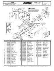
PARTS LISTINDOOR UNITRef.No.DescriptionASY9USCCWPart No.ASY12USCCWOrd.Q`ty34 Capacitor (Fan Motor) 9900089061 990008906163 Panel (Front) Total Assy 9312417032 931241706365 Flow Control Panel-Z 9306058012 930605801269 Louver-A9306055028 930605502874 Filter 9305444014 9305444014108 Base9309755062 9309755062109 Casing9306052027 9306052027122 Shaft Holder -B9303066010 9303066010127 Drain Hose Assy 9305550029 9305550029146 Evaporator Assy9330144019 9330144019151 Control Box 9330007017 9330007017158 Connecting Pipe Assy 9306416010 9306416010164 Fan Motor Assy-IN 9601171010 9601171010169 Cross-Flow Fan Assy 9307836015 9307836015178 Motor Cushion -M9601302018 9601302018184 Thermistor Sping313728262708 313728262708188 Power Cord Assy 9702595043 9702595043196 Clamp SKB-150313035356905 313035356905233 Power Transformer9900028015 9900028015235 Thermistor Assy -Pipe 9702039059 9702039059236 Controller PCB Assy 9704865038 9704865014240 Remote Control Unit 9312058020 9312058020281 Clamp Metal (Pipe) 9306063009 9306063009283 Bushing-A9303529010 9303529010323 Louver-B 9306056025 9306056025385 PCB (Power and Indicator) 9704870018 9704870018401 Wall Hook Bracket 9304358008 9304358008440 Flow Control Panel-U 9306057015 9306057015466 Clamp NK-4N313714328805 313714328805522-1 Gear-A 9306062002 9306062002523 Gear Bracket 9306407001 9306407001652-1 Thermistor Holder Pipe 313714262805 313714262805668 Screw w/Washer313681304205 313681304205759 Intake Grill -A9330001015 9330001015764 Drain Cap Assy 9304150008 9304150008767-1 Bottom Cover -A 9330004016 9330004016777 Clamper (Grille)9306755010 9306755010815 Terminal9900040048 9900040048850 Window (Receiver9330003019 9330003019872 Indicator Case9330009011 9330009011873 Lamp Cover9330014015 9330014015874 Control Box Cover 9330008014 9330008014876 Step Motor 9900139018 9900139018877 Face Panel (Front)-A 9330005044 93300050442004.11.3014W hen you order parts, please make a photocopy of this pageand fill the number of the parts in the "Order" column.
OUTDOOR UNITRef.No.DescriptionAOY9USCCPart No.AOY9UFCCOrd.Q'tyRef.No.DescriptionPart No.AOY12USCCOrd.Q'ty4 Emblem-Rear93084680175 Cabinet Front Panel, Plastic 93060160127 Connector Cover 93060180169 Cabinet Rear Panel, Plastic 930601701912 Base Assy, Painted 930480604213 3-Way Valve931286301314 2-Way Valve 931286201616 Condenser Assy9309104020930846801793060160129306018016930601701993048060429312863013931286201693091040204 Emblem-Rear5 Cabinet Front Panel, Plastic7 Connector Cover9 Cabinet Rear Panel, Plastic12 Base Assy, Painted13 3-Way Valve14 2-Way Valve16 Condenser Assy9308468017930638601693061190109306385019930611802093128650179312864010930845903932 Control Box Metal 930647502434 Capacitor (Fan Motor) 990008902337 Capacitor (Running)930758806838 Clamp Metal (Capacitor) 31346806180839 Propeller Fan 930656501541 Fan Motor Assy-Out 930709501642 Bracket (Motor)930602101646 Compressor Assy9311012016930647502499000890239307588013313468061808930656501593070950169306021016931442901932 Control Box Metal34 Capacitor (Fan Motor)3738Capacitor (Running)Clamp Metal (Capacitor)39 Propeller Fan41 Fan Motor Assy-Out42 Bracket (Motor)46 Compressor Assy930856102299000890309307588013313468061808930553800393077150209305536016931113301848 Fan Ring 930601902062 Wire Assy (Shield)-A 9305791026138 Separate Wall Metal 9306474003195 Clamp SKB-100313361275805196-2 Clamp SKB-3MC 9305335008230 Overload Relay9311143000343 Solenoid Coil9970003011344 4-Way Valve9900162016365 Bracket (Valve)9306020026412 Terminal Gasket (For Comp.) 9351505011674 Screw, SUS410T +5014 9305848010688 Screw w/Washer 313681304205765 Drain Pipe (L-<strong>type</strong>)9301102000766 Drain Pipe Packing9301143003781 Rubber Cushion9312680016815 Terminal-4P9306488017935 Reinforcement Plate9306473006942 Control Box Cover Metal 9306476007942-2 Control Box Cover-B Metal 9305975006982 Cord Clamp, Plastic 9302271002985 Special Nut w/Washer 9304902003986 Special Washer 9304903000A Screw (with Inner Washer) 9357297002---- BR Sheet 180x180x T2 93050390679306019020930569502793064740033133612758059305335008-----9970003011990016201693060200269314432002930584801031368130420593011020009301143003931268001693064880179306473006930647600793059750069302271002930490200393049030009357297002930503906751 Special Nut M5930709100155 Special Nut M631325225770198 Fan Ring 9305581023109138Terminal CoverSeparate Wall Metal93070900049305971008187 Clamp No.1219313361271706195 Clamp SKB-100313361275805196 Clamp SKB-150313035356905196-2230343344365Clamp SKB-3MC 9305335008Overload Relay9312899005Solenoid Coil99700030114-Way Valve9900162016930674801293511210069305848010313681304205Bracket (Valve)412 Terminal Gasket (For Comp.)674 Screw, SUS410T +5014688 Screw w/Washer765 Drain Pipe (L-<strong>type</strong>)9301102000766 Drain Pipe Packing9301143003815916935-1Terminal-4PNoise Insulation -AReinforcement(Cabinet TOP)930648801793063620039305973002935-2 Reinforcement -F (Cabinet Top) 9306123000942-1 Control Box Cover-A Metal9308562012942-2 Control Box Cover-B Metal 9305975006946 Inlet Pipe 9306401009982 Cord Clamp, Plastic9302271002A Screw (with Inner Washer)9357297002B Screw (with Spring Washer) 0700179013---- BR Sheet 60x100x T5 9305039012---- BR Sheet 40x80x T5 9305039043---- BR Sheet 180x180x T2 93050390672005.01.2115When you order parts, please make a photocopy of this pageand fill the number of the parts in the "Order" column.
STANDARDACCESSORIESName and ShapePart No.Wall hook bracket9304358008Remote controlunit9312058020Battery (penlight)0600185534Tapping screw( O4 x 25 )0700076046Cloth tape9308117007Drain pipe(Including drain packing)93030290152004.12.0116
0309G2374