MINIATURE MONO RAIL (pdf; EN) - Rollon
MINIATURE MONO RAIL (pdf; EN) - Rollon
MINIATURE MONO RAIL (pdf; EN) - Rollon
- No tags were found...

Create successful ePaper yourself
Turn your PDF publications into a flip-book with our unique Google optimized e-Paper software.
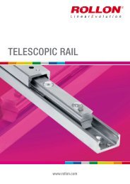
<strong>MINIATURE</strong> <strong>MONO</strong> <strong>RAIL</strong>www.rollon.com
About <strong>Rollon</strong>Development of global businessContinual expansion and optimization of the portfolio1975 Parent company, <strong>Rollon</strong> S.r.l., founded in Italy1991 Founding of <strong>Rollon</strong> GmbH in Germany1995 Expansion of headquarters to new 4,000 m 2 factoryAssembly starts in GermanyQuality management certified to ISO 90011998 <strong>Rollon</strong> B.V. in the Netherlands and <strong>Rollon</strong> Corporation in theUSA are foundedExpansion of German branch to new 1,000 m 2 plant1999 Founding of <strong>Rollon</strong> S.A.R.L. in FranceEnvironmental management certified to ISO 140012000 <strong>Rollon</strong> s.r.o. founded in Czech Republic2001 Expansion of headquarters to new 12,000 m 2manufacturing plant2007 Restructuring of the GmbH and alignment of production inGermany to customer-specific adaptationsTakeover of the assets of a manufacturer of linear railsystems2008 Expansion of sales network in Eastern Europe and AsiaFounded in 1975, <strong>Rollon</strong> manufactured high-precision linear roller bearingsfor the machine tool industry. Early on, <strong>Rollon</strong> started manufacturinglinear bearings based on the bearing-cage design. In 1979, the CompactRail self-aligning linear bearings joined the Telescopic Rail industrialdrawer slides and Easy Rail linear bearings and became the basisof the strong foundation on which the company is building upon today.Continuing optimization of these core products still remains one of themost important goals at <strong>Rollon</strong>. The development of the patented CompactRail linear bearing, which uses different proprietary rail profiles and highprecisionradial ball bearing sliders, enables the compensation of heightand angle mounting defects in applications, and is only one example ofthe continuing efforts to innovative the development of our existing productfamilies. In the same manner, we continually introduce innovativenew product familiesdisplaying our continuing product development andoptimization in the industry. These include:■ 1994 Light Rail - full and partial extension telescopic in lightweightdesign■ 1996 Uniline - belt driven linear actuators■ 2001 Ecoline - economical aluminum linear actuators■ 2002 X-Rail - inexpensive formed steel linear guides■ 2004 Curviline - curved monorail profile rail guide with roller carriages■ 2007 Monorail - miniature sizes and full sizedEach further innovation of our linear bearings is built upon the our extensiveknowledge of the nine product families in production today as well ason the current market demands. <strong>Rollon</strong> is the ultimate linear technologyfor any application needs.
Content1 Product explanationMono Rail Miniature Profile Rails2 Technical dataPerformance characteristics and remarksLoad capacities3 Product dimensionsStandard widthLarge width4 Technical instructionsPrecisionPreload, LubricationFriction, SealLoadingService lifeInstallation instructions46789101113141617Ordering keyOrdering key with explanations and hole patternPortfolio
Product explanation 1Standard widthCompact technology and high performance inits smallest structural shape.Fig. 2Large widthWide miniature profile rails, with a compactsize, allow the acceptance of higher forces andmoments. Especially suited for single rail applications.Fig. 3Unique ball return circulationThe return channels and redirection for thestainless steel balls are made completely outof plastic. The efficient design principle reducescontact between the balls and the metal body.This in turn reduces the generation of noise duringoperation. The well-thought-out lubricatingprinciple with lubricant reservoir integrated inthe ball recirculation increases the time betweenlubrication intervals.Fig.4Integrated redirectionDuring the carriage movements, the plasticend caps are subjected to permanent shockscaused by the continuous change of directionof movement. These shock loads have a criticalinfluence on the running properties and speed.Automation and production demands of modernindustry call for high operating speeds. The integratedball redirection, i.e., the direct connectionof ball redirection and body, creates an optimumsolution for the miniature profile rails.Fig.5www.rollon.com5
2 Technical dataTechnical dataFig. 6Performance characteristics:■ Available sizes of standard width: 7, 9, 12, 15■ Available sizes of large width: 9, 12, 15■ More sizes on request■ Max. operating speed:3 m/s ( 118 in/s ) ( depending on application )■ Max. acceleration:250 m/s² ( 9,844 in/s² ) (depending on application)■ Temperature range: -40 °C to +80 °C (-40 °F to +176 °F ),temporary temperature peaks are possible up to +100 °C (+212 °F )■ Available single rail lengths up to 1,000 mm ( 39.37 in )Remarks:■ Combining rails is possible ( joining )■ Alternative rail fixing possible on request■ Three preload classes: V 0, V S, V 1■ Three precision classes: P, H, N■ Gothic arch profile with 45° contact angle for the same load capacityin all principle directions■ Corrosion resistant steel6 www.rollon.com
Technical data 2Load capacitiesStandard widthC 0M zM yM xFig. 7TypeLoad capacities[N]Static moments[Nm]dyn. C 100stat. C 0M xM yM zMR07MN 890 1400 5.2 3.3 3.3MR09MN 1570 2495 11.7 6.4 6.4MR12MN 2308 3465 21.5 12.9 12. 9MR15MN 3810 5590 43.6 27 27Tab. 1Large widthM yM xC 0C 0C 0M zFig. 8TypeLoad capacities[N]Static moments[Nm]dyn. C 100stat. C 0M xM yM zMR09WN 2030 3605 33.2 13.7 13.7MR12WN 3065 5200 63.7 26.3 26.3MR15WN 5065 8385 171.7 45.7 45.7Tab. 2www.rollon.com7
3 Product dimensionsProduct dimensionsStandard widthFig. 9TypeSystem[mm]H W W 2H 2MR07MN 8 17 5 6.5MR09MN 10 20 5.5 7.8MR12MN 13 27 7.5 10MR15MN 16 32 8.5 12Tab. 3TypeSlider[mm]Rail[mm]L P 2P 1M g 2L 1T S Ø Weight[kg]W 1H 1P d D g 1Weight[kg/m]MR07MN 23.7 12 8 M2 2.5 14.3 2.8 1.6 1.1 0.008 7 4.7 15 2.4 4.2 2.3 0.215MR09MN 30.6 15 10 M3 3.0 20.5 3.3 2.2 1.3 0.018 9 5.5 20 3.5 6 3.5 0.301MR12MN 35.4 20 15 M3 3.5 22.0 4.3 3.2 1.3 0.034 12 7.5 25 3.5 6 4.5 0.602MR15MN 43.0 25 20 M3 5.5 27.0 4.3 3.3 1.8 0.061 15 9.5 40 3.5 6 4.5 0.93Tab. 48 www.rollon.com
Product dimensions 3Large widthMR15WFig. 10TypeSystem[mm]H W W 2H 2MR09WN 12 30 6 8.6MR12WN 14 40 8 10.1MR15WN 16 60 9 12Tab. 5TypeSlider[mm]Rail[mm]L P 2P 1M g 2L 1T S Ø Weight[kg]W 1H 1P P 3d D g 1Weight[kg/m]MR09WN 39.1 21 12 M3 3 27.9 4 2.6 1.3 0.037 18 7.3 30 - 3.5 60.94MR12WN 44.4 28 15 M3 3.5 31.0 4.5 3.1 1.3 0.065 24 8.5 40 - 4.5 8 4.5 1.472MR15WN 55.3 45 20 M4 4.5 38.5 4.5 3.3 1.8 0.137 42 9.5 40 23 4.5 8 2.818Tab. 6www.rollon.com9
4 Technical instructionsTechnical instructionsPrecisionThere are three precision classes to choose from for the Mono Rail Miniatureprofile rails: Classes P, H, and N are manufactured.PHPW2Fig. 11Precision classesPrecision P[µm]High H[µm]Normal N[µm]H Tolerance of height H ± 10 ± 20 ± 40∆HPermissible height difference of differentcarriages at the same position on the rail7 15 25W 2Tolerance of width W 2± 15 ± 25 ± 40∆W 2Permissible width difference of differentcarriages at the same position on the rail10 20 30Tab. 7Running accuracyRunning accuracy (parallelism)µmmmLength of guide railFig. 1210 www.rollon.com
Technical instructions 4PreloadThe Mono Rail Miniature profile rails are available in the three differentpreload classes V 0, V Sand V 1(see table 8). The preload influences the rigidity,precision and torque resistance and also affects the product servicelife and displacement force.TypePreload classesSmall clearanceVery quiet runningStandardVery quiet and preciserunningSmall preloadHigh rigidity, vibrationreduced, high precision,good load balanceV 0[µm]V S[µm]V 1[µm]MR07 +4 to +2 +2 to 0 0 to -3MR09 +4 to +2 +2 to 0 0 to -4MR12 +5 to +2 +2 to 0 0 to -5MR15 +6 to +3 +3 to 0 0 to -6Tab. 8LubricationFunctionThe contact points between ball and track are separated from each otherby a microscopically thin oil film. The lubrication effects:■ Reduction of friction■ Reduction of wear■ Corrosion protection■ Better thermal distribution and therefore increased of service lifeFig. 13www.rollon.com11
4 Technical instructionsImportant instructions for lubrication■ Mono Rail Miniature profile rails must be lubricated for operation.■ The carriage must be moved back and forth during lubrication.■ The lubricant can also be applied to the tracks.■ The lubricant can be injected into the lubrication holes on both sides ofthe carriage.■ There should be a thin film of lubricant on the rail surface at all times.■ Please inform us in advance if the guides are to be used in acid or basecontaining environments or in clean rooms.■ Please contact the sales department if the oil lubrication should beused for vertical use of the guide.■ If the stroke is < 2 or > 15 times the carriage length, the lubricationintervals should be more often.Grease lubricationWhen using grease lubrication, we recommend synthetic-oil based lithiumgrease with a viscosity according to ISO VG 32 to ISO VG 100.Oil lubricationWe recommend CLP or CGLP synthetic oil conforming to DIN 51517 orHLP to DIN 51524 and a viscosity range conforming to ISO VG 32 toISO VG 100 for operating temperatures between 0 °C and +70 °C. Werecommend a viscosity according to ISO VG 10 for use at low temperatures.For application-specific special lubrication please contact the <strong>Rollon</strong>Application engineering department.‹mm2ISO VG 10 = Viscosity of 10 s at 40 °Cmm 2ISO VG 32 = Viscosity of 32 s at 40 °C‹ ‹mm 2ISO VG 100 = Viscosity of 100 s at 40 °CTypeFirst lubrication[cm 3 ]MR07MN 0.12MR09MN 0.23MR12MN 0.41MR15MN 0.78TypeLubrication intervalsOperating speed, stroke length and ambient conditions influence theselection of time between lubrication intervals. Establishing a safe lubricationinterval is based exclusively on the experienced practiced valuesdetermined on site. However, a lubrication interval should not be longerthan one year in any case.RelubricationFirst lubrication[cm 3 ]MR09WN 0.30MR12WN 0.52MR15WN 0.87■ Relubrication of the system must be done before the lubricant used isdirty or shows discolouration.■ An application of approx. 50 % of the quantity used for first lubricationis sufficient for relubrication ( see tab. 9f).■ Relubrication is performed at operating temperature.During relubrication, the carriage should be moved back and forth.■ If the stroke is < 2 or > 15 times the carriage length, the lubricationintervals should be more often.Tab. 9Tab. 10Fig. 1412 www.rollon.com
Technical instructions 4FrictionThe Mono Rail Miniature profile rails have a low friction characteristicwith constant running resistance and low breakaway force.F m= µ · FF = load (N)F m= friction force (N)Fig. 15Mono Rail Miniature profile rails have a coefficient of friction of approx.Causes of friction■ Friction of the sealing systemµ = 0.002 - 0.003.■ Friction of the balls with each other■ Friction between balls and redirection■ Rolling resistance of the balls in the gothic arch running grooves■ Resistance of lubricant in the carriage■ Resistance by contamination in the lubricantFriction with lubricated end sealTypeM[N max]W[N max]MR07 0.1 -MR09 0.1 0.8MR12 0.4 1.0MR15 1.0 1.0Tab. 11SealThe carriages of the Miniature Mono Rail are equipped with end seals onboth sides.The design of the end seal ensures a good and dust-proof seal. This extendsthe product service life, reduces the loss of lubricant and guaranteesthe optimum system lubrication over a long time.The special design of the stripper allows a low seal resistance and has nonegative influence on the running behaviour of the system.Fig. 16www.rollon.com13
4 Technical instructionsLoadingStatic load (P 0) and static moment (M 0)Permissible static loadThe permissible static load of the Mono Rail Miniature profile rail is limitedby:■ Static load of each linear guide■ Permissible load of the fixing screws■ Permissible load of all components used in the surroundingconstruction■ Static safety factor, which is required by the correspondingapplicationThe equivalent static load and the static moment are the largest load, orthe largest moment, which are calculated based on formulas 3 and 4.Static safety factor S 0When observing the static safety factor S 0the Mono Rail Miniature profilerails allow a permissible operation and high running precision as isrequired for each application. Calculation of the static safety factor S 0:see fig. 17S 0static safety factorC 0static load capacity in loading direction (N)P 0equivalent static load (N)M 0static moment in loading direction (Nm)M equivalent static moment in loading direction (Nm)Static load capacity C 0The static load capacity C 0of ball recirculating guides is defined accordingto DIN 636, Part 2 as the only load which gives a Hertzian stress of 4,200MPa with the existing lubrication between track and balls in the center ofthe highest loaded contact surface.Note: In the loading center, there is a permanent deformation of approx0.01 % of the ball diameter under this load (according to DIN 636, Part 2).S 0= C 0/ P 0Formula 1 Operating conditions S 0S 0= M 0/ M Formula 2 Normal operation 1 ~ 2P 0= F maxFormula 3 Loading with vibration or shock effect 2 ~ 3M 0= M maxFormula 4 High precision and smooth running ≥ 3Fig. 1714 www.rollon.com
Technical instructions 4Dynamic load capacity CIf the dynamic loads work vertically on the last zones with equal size anddirection, the calculated service life of the linear guide can theoreticallyreach 100 km piston travel (as per DIN 636, Part 2).Combined loads in combination with momentsIf both loads and moments work on the profile rails, the equivalent dynamicload is calculated with formula 9. According to DIN 636, Part 1, theequivalent load should not exceed ½ C.Equivalent dynamic load and speedWith changing load and speed, these must be considered individually sinceeach parameter helps determine the service life.Equivalent dynamic loadIf only the load changes, the equivalent dynamic load can be calculatedwith formula 5.Equivalent speedIf only the speed changes, the equivalent speed is calculated with formula 6.If speed and load change, the equivalent dynamic load is calculated withformula 7.Combined dynamic loadWith combined exterior load in an arbitrary angle, the equivalent dynamicload is calculated with formula 8.3 3 3qP = 3 –––––––––––––––––––––– 1· F 1+ q 2· F 2+ ··· q n· F nFormula 5100qv = ––––––––––––––––––– 1· v 1+ q 2· v 2+ ··· q n· v nFormula 61003 3 3qP = 3 ––––––––––––––––––––––––––––– 1· v 1· F 1+ q 2· v 2· F 2+ ··· q n· v n· F nFormula 7100P = | F X| + | F Y| Formula 8| MP = | F X| + | F Y| + ( 1| | M+ 2| | M+ 3|) · CM0xM yM zFormula 9P = equivalent dynamic load (N)q = stroke (in %)F 1vvFF YF XC 0= individual load levels (N)= average speed (m/min)= individual speed levels (m/min)= external dynamic load (N)= external dynamic load – vertical (N)= external dynamic load – horizontal (N)= static load capacity (N)M 1, M 2, M 3= external moments (Nm)M x, M y, M z= maximum permissible moments in the differentloading directions (Nm)Fig. 18www.rollon.com15
4 Technical instructionsService lifeAn example of a profile rail or a lot of identical profile rails under thesame running conditions, which use ordinary materials with normalmanufacturer‘s quality and operating conditions, can reach 90 % of thecalculated service life (as per DIN 636 Part 2). By taking 50 km traverseas a basis, the dynamic load capacity is usually 20 % over the values asper DIN. The relationship between the two load capacities can be seenfrom formulas 10 and 11.Calculation of service lifeFormulas 12 and 13 are used for calculating the service life, if equivalentdynamic load and average speed are constant.C (50)= 1,26 · C (100)Formula 10C (100)= 0,79 · C (50)Formula 11C 100L = ( ––– ) 3 · 10 5 Formula 12PC 100L LL h= ––––––––––– = ––– · ( ––– ) 3 Formula 132 · s · n · 60 PV mL = service life based on 100,000 (m)L h= service life (h)C = dynamic load capacity (N)P = equivalent dynamic load (N)S = stroke length (m)n = stroke frequency (min -1 )V m= average speed (m/min)Fig. 1916 www.rollon.com
1Technical instructions 4Installation instructionsShoulder heights and radius of stop edgesRounding of the stop edges of the surrounding construction should bemade so as to avoid contact with the edges of the carriage and the rail.Please observe the following table with the information on the radius andheight of the stop surfaces.r2Eh2h1Fig. 20Dimensions of the stop edgesType h 1[mm]r 1max[mm]h 2[mm]r 2max[mm]E[mm]Type h 1[mm]r 1max[mm]h 2[mm]r 2max[mm]E[mm]MR07M 1.2 0.3 2.8 0.3 1.5MR09M 1.5 0.3 3 0.3 2.2MR12M 2.5 0.5 4 0.5 3MR15M 2.5 0.5 4.5 0.5 4Tab. 12MR09W 2.5 0.3 3 0.3 3.4MR12W 2.5 0.5 4 0.5 3.9MR15W 2.5 0.5 4.5 0.5 4Tab. 13Geometric and positional accuracy of the mounting surfacesInaccuracies of the mounting surface negatively influence the running accuracyand reduce the service life of the Mono Rail Miniature profile rails.If the inaccuracies of the mounting surfaces exceed the values calculatedusing formulas 14, 15 and 16, the service life is shortened according toformulas 12 und 13.Mounting surfaceThe mounting surface should be ground or milled very finely and have asurface roughness of R a1.6.Reference surfaceRail: Both sides of the rails can be used as a reference surface withoutfurther marks.Slider: The reference surface is located across from the running side identifiedwith a notch mark.www.rollon.com17
Ordering keyOrdering keyRail / slider systemMR 15 M N SS 2 V1 P 310Rail length see tab. 17 and 18Precision class see pg. 10, tab. 7Preload class see pg. 11, tab. 8Number of sliders on one railEnd sealSlider typeRail type see pg. 8, tab. 3 / pg. 9, tab. 5Rail width see pg. 8, tab. 3 / pg.9, tab. 5Product typeOrdering example: MR15MN-SS-2-V1-P-310Hole pattern: 15 -7 x 40 -15, see fig. 24, tab. 17 / fig. 25, tab. 18
PortfolioPortfolioCOMPACT <strong>RAIL</strong>Rugged roller sliders with innovativeself adjustment<strong>MONO</strong> <strong>RAIL</strong>Profile guideways for highest degreesof precisionCURVILINECurvilinear rails for constantand variable radiiTELESCOPIC <strong>RAIL</strong>Smooth-running telescopic linearbearing drawer slides withlow deflection under heavy loadsEASY <strong>RAIL</strong>Compact, versatile linear bearingsX-<strong>RAIL</strong>Roller embossed stainless steel profilesfor the use in rough environmentsUNILINESteel-reinforced, belt-driven linear actuators withhardened steel linear bearingsand precision radial ball bearing rollersLIGHT <strong>RAIL</strong>Full and partial extension, lightweightdrawer slides
Fold out ordering keyFold out ordering keyTo make this product catalog as simple as possible for you to use, we haveincluded the following easy-to-read chart.Your advantages:■ Description and ordering designations easy to read at one glance■ Simplified selection of the correct product■ Links to detailed descriptions in the catalog
ROLLON S.r.l.Via Trieste 26I-20871 Vimercate (MB)Tel.: (+39) 039 62 59 1Fax: (+39) 039 62 59 205E-Mail: infocom@rollon.itItalywww.rollon.itGermanyROLLON GmbHBonner Strasse 317-319D-40589 DüsseldorfTel.: (+49) 211 95 747 0Fax: (+49) 211 95 747 100E-Mail: info@rollon.dewww.rollon.deNetherlandsROLLON B.V.Ringbaan Zuid 86905 DB ZevenaarTel.: (+31) 316 581 999Fax: (+31) 316 341 236E-Mail: info@rollon.nlwww.rollon.nlFranceROLLON S.A.R.L.Les Jardins d‘Eole, 2 allée des SéquoiasF-69760 LimonestTel.: (+33) (0)4 74 71 93 30Fax: (+33) (0)4 74 71 95 31E-Mail: infocom@rollon.frwww.rollon.frUSAROLLON Corporation101 Bilby Road. Suite BHackettstown, NJ 07840Tel.: (+1) 973 300 5492Fax: (+1) 908 852 2714E-Mail: info@rolloncorp.comwww.rolloncorp.comAll addresses of our global sales partners can alsobe found in the internet at www.rollon.comChanges and errors excepted. The text and images may be used only with our permission.RL_MMR_<strong>EN</strong>_04/13