CAN J1939 Module High Amp Relay XHA2 - GSNA.com
CAN J1939 Module High Amp Relay XHA2 - GSNA.com CAN J1939 Module High Amp Relay XHA2 - GSNA.com
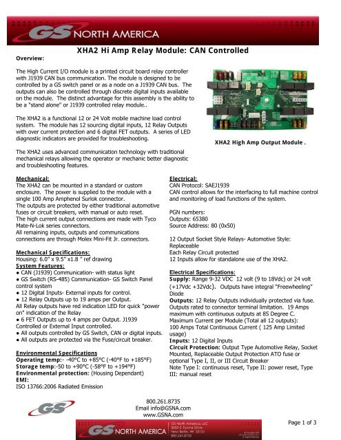
Overview:XHA2 Hi Amp Relay Module: CAN ControlledThe High Current I/O module is a printed circuit board relay controllerwith J1939 CAN bus communication. The module is designed to becontrolled by a GS switch panel or as a node on a J1939 CAN bus. Theoutputs can also be controlled through discrete digital inputs availableon the module. The distinct advantage for this assembly is the ability tobe a "stand alone" or J1939 controlled relay module..The XHA2 is a functional 12 or 24 Volt mobile machine load controlsystem. The module has 12 sourcing digital inputs, 12 Relay Outputswith over current protection and 6 digital FET outputs. A series of LEDdiagnostic indicators are provided for troubleshooting.The XHA2 uses advanced communication technology with traditionalmechanical relays allowing the operator or mechanic better diagnosticand troubleshooting features.XHA2 High Amp Output Module .Mechanical:The XHA2 can be mounted in a standard or customenclosure. The power is supplied to the module with asingle 100 Amp Amphenol Surlok connector.The outputs are protected by either traditional automotivefuses or circuit breakers, with manual or auto reset.The high current output connections are made with TycoMate-N-Lok series connectors.All remaining inputs, outputs and communicationsconnections are through Molex Mini-Fit Jr. connectors.Mechanical Specifications:Housing: 6.0” x 9.5” x1.8 ” ref drawingSystem Features:● CAN (J1939) Communication- with status light● GS Switch (RS-485) Communication- GS Switch Panelcontrol system● 12 Digital Inputs- External inputs for control.● 12 Relay Outputs up to 19 amps per Output.All Relay outputs have red indication LED for quick "poweron" indication of the Relay● 6 FET Outputs up to 4 amps per Output. J1939Controlled or External Input controlled.● All outputs controlled by GS Switch, CAN or digital inputs.● All outputs are protected via the Fuse/circuit breaker.Environmental SpecificationsOperating temp:- -40°C to +85°C (-40°F to +185°F)Storage temp:-50 to +90°C (-58°F to +194°F)Environmental protection: (Housing Dependant)EMI:ISO 13766:2006 Radiated EmissionElectrical:CAN Protocol: SAEJ1939CAN control allows for the interfacing to full machine controland monitoring of load functions of the system.PGN numbers:Outputs: 65380Source Address: 80 (0x50)12 Output Socket Style Relays- Automotive Style:ReplaceableEach Relay Circuit protected12 Inputs allow for standalone use of the XHA2.Electrical Specifications:Supply: Range 9-32 VDC 12 volt (9 to 18Vdc) or 24 volt(+17Vdc +32Vdc). Outputs have integral “Freewheeling”DiodeOutputs: 12 Relay Outputs individually protected via fuse.Outputs rated to connector terminal limitation. 19 Ampsmaximum with continuous outputs at 85 Degree C.Maximum Current per Module (Total all 12 outputs):100 Amps Total Continuous Current ( 125 Amp Limitedusage)Inputs: 12 Digital InputsCircuit Protection: Output Type Automotive Relay, SocketMounted, Replaceable Output Protection ATO fuse oroptional Type I, II, or III Circuit BreakerNote Type I: continuous reset, Type II: power reset, TypeIII: manual reset800.261.8735Email info@GSNA.comwww.GSNA.com. Page 1 of 3
- Page 2 and 3: ESD:ISO 10605:2001 Air: 15kV, Conta
Overview:<strong>XHA2</strong> Hi <strong>Amp</strong> <strong>Relay</strong> <strong>Module</strong>: <strong>CAN</strong> ControlledThe <strong>High</strong> Current I/O module is a printed circuit board relay controllerwith <strong>J1939</strong> <strong>CAN</strong> bus <strong>com</strong>munication. The module is designed to becontrolled by a GS switch panel or as a node on a <strong>J1939</strong> <strong>CAN</strong> bus. Theoutputs can also be controlled through discrete digital inputs availableon the module. The distinct advantage for this assembly is the ability tobe a "stand alone" or <strong>J1939</strong> controlled relay module..The <strong>XHA2</strong> is a functional 12 or 24 Volt mobile machine load controlsystem. The module has 12 sourcing digital inputs, 12 <strong>Relay</strong> Outputswith over current protection and 6 digital FET outputs. A series of LEDdiagnostic indicators are provided for troubleshooting.The <strong>XHA2</strong> uses advanced <strong>com</strong>munication technology with traditionalmechanical relays allowing the operator or mechanic better diagnosticand troubleshooting features.<strong>XHA2</strong> <strong>High</strong> <strong>Amp</strong> Output <strong>Module</strong> .Mechanical:The <strong>XHA2</strong> can be mounted in a standard or customenclosure. The power is supplied to the module with asingle 100 <strong>Amp</strong> <strong>Amp</strong>henol Surlok connector.The outputs are protected by either traditional automotivefuses or circuit breakers, with manual or auto reset.The high current output connections are made with TycoMate-N-Lok series connectors.All remaining inputs, outputs and <strong>com</strong>municationsconnections are through Molex Mini-Fit Jr. connectors.Mechanical Specifications:Housing: 6.0” x 9.5” x1.8 ” ref drawingSystem Features:● <strong>CAN</strong> (<strong>J1939</strong>) Communication- with status light● GS Switch (RS-485) Communication- GS Switch Panelcontrol system● 12 Digital Inputs- External inputs for control.● 12 <strong>Relay</strong> Outputs up to 19 amps per Output.All <strong>Relay</strong> outputs have red indication LED for quick "poweron" indication of the <strong>Relay</strong>● 6 FET Outputs up to 4 amps per Output. <strong>J1939</strong>Controlled or External Input controlled.● All outputs controlled by GS Switch, <strong>CAN</strong> or digital inputs.● All outputs are protected via the Fuse/circuit breaker.Environmental SpecificationsOperating temp:- -40°C to +85°C (-40°F to +185°F)Storage temp:-50 to +90°C (-58°F to +194°F)Environmental protection: (Housing Dependant)EMI:ISO 13766:2006 Radiated EmissionElectrical:<strong>CAN</strong> Protocol: SAE<strong>J1939</strong><strong>CAN</strong> control allows for the interfacing to full machine controland monitoring of load functions of the system.PGN numbers:Outputs: 65380Source Address: 80 (0x50)12 Output Socket Style <strong>Relay</strong>s- Automotive Style:ReplaceableEach <strong>Relay</strong> Circuit protected12 Inputs allow for standalone use of the <strong>XHA2</strong>.Electrical Specifications:Supply: Range 9-32 VDC 12 volt (9 to 18Vdc) or 24 volt(+17Vdc +32Vdc). Outputs have integral “Freewheeling”DiodeOutputs: 12 <strong>Relay</strong> Outputs individually protected via fuse.Outputs rated to connector terminal limitation. 19 <strong>Amp</strong>smaximum with continuous outputs at 85 Degree C.Maximum Current per <strong>Module</strong> (Total all 12 outputs):100 <strong>Amp</strong>s Total Continuous Current ( 125 <strong>Amp</strong> Limitedusage)Inputs: 12 Digital InputsCircuit Protection: Output Type Automotive <strong>Relay</strong>, SocketMounted, Replaceable Output Protection ATO fuse oroptional Type I, II, or III Circuit BreakerNote Type I: continuous reset, Type II: power reset, TypeIII: manual reset800.261.8735Email info@<strong>GSNA</strong>.<strong>com</strong>www.<strong>GSNA</strong>.<strong>com</strong>. Page 1 of 3
ESD:ISO 10605:2001 Air: 15kV, Contact: 8kVConnections:J1 Connector:Mating Connector: <strong>Amp</strong>henol C10-647184-061Pin 1: +Supply (100 <strong>Amp</strong>) (Continuous)J2 Connector:Mating Connector: Tyco 1-480702-0Pin 1: +Battery SupplyPin 2: Power Switch SupplyPin 3: Power Point (+)Pin 4: Common SupplyJ3 Connector: Machine ConnectionMating Connector: Molex 39-01-2125Pin 1: +Ignition SupplyPin 2: 5 <strong>Amp</strong> Continuous PowerPin 3: 5 <strong>Amp</strong> Switched PowerPin 4: IndicatorPin 5: Crane Hour Meter(Through connect to J9)Pin 6: PTO Hour Meter(Through connect to J9)Pin 7: Digital Input 1Pin 8: Digital Input 2Pin 9: Digital Input 3Pin 10: Digital Input 4Pin 11: Digital Input 5Pin 12: Digital Input 6J4 Connector: Can ConnectionMating Connector: Molex 39-01-3042Pin 1: <strong>CAN</strong>-HPin 2: <strong>CAN</strong>-LPin 3: <strong>CAN</strong> ShieldPin 4: No ConnectionJ5 Connector: <strong>Relay</strong> Outputs 1-7Mating Connector: Tyco 1-480763-0Pin 1: <strong>Relay</strong> 1Pin 2: <strong>Relay</strong> 2Pin 3: <strong>Relay</strong> 3Pin 4: <strong>Relay</strong> 4Pin 5: <strong>Relay</strong> 5Pin 6: <strong>Relay</strong> 6Pin 7: <strong>Relay</strong> 7Pin 8: No ConnectionPin 9: No Connection<strong>XHA2</strong> Hi <strong>Amp</strong> <strong>Relay</strong> <strong>Module</strong>: <strong>CAN</strong> ControlledJ6 Connector: <strong>Relay</strong> Outputs 8-12Mating Connector: Tyco 1-480706-0Pin 1: <strong>Relay</strong> 8Pin 2: <strong>Relay</strong> 9Pin 3: <strong>Relay</strong> 10Pin 4: <strong>Relay</strong> 11Pin 5: <strong>Relay</strong> 12J7 Connector: FET Outputs- 4 <strong>Amp</strong> ControlMating Connector: Molex 39-01-2100Pin 1: FET Out 1Pin 2: FET Out 2Pin 3: FET Out 3Pin 4: FET Out 4Pin 5: FET Out 5Pin 6: FET Out 6Pin 7: FET Common SupplyPin 8: FET Common SupplyPin 9: FET Common SupplyPin 10: FET Common SupplyJ8 Connector: FET External Input ControlMating Connector: Molex 39-01-2080Pin 1: <strong>Relay</strong> or FET Input 1Pin 2: <strong>Relay</strong> or FET Input 2Pin 3: <strong>Relay</strong> or FET Input 3Pin 4: <strong>Relay</strong> or FET Input 4Pin 5: <strong>Relay</strong> or FET Input 5Pin 6: <strong>Relay</strong> or FET Input 6Pin 7: Switch SupplyPin 8: Switch SupplyJ9 Connector:Mating Connector: Molex 39-01-4040Pin 1: Accessory Hour MeterPin 2: Crane Hour Meter from Pin 5 J3 ConnectorPin 3: PTO Hour Meter from Pin 6 J3 ConnectorPin 4: Hour Meter Common SupplyJ9 Connector: Switch panel Control RS-485Mating Connector: Molex 39-01-2060Pin 1: Switch Panel RS-485-APin 2: Switch Panel Common SupplyPin 3: Switch Panel +5VDC SupplyPin 4: Switch Panel RS-485-/BPin 5: No ConnectionPin 6: Switch Panel Shield800.261.8735Email info@<strong>GSNA</strong>.<strong>com</strong>www.<strong>GSNA</strong>.<strong>com</strong>. Page 2 of 3
<strong>XHA2</strong> Hi <strong>Amp</strong> <strong>Relay</strong> <strong>Module</strong>: <strong>CAN</strong> Controlled800.261.8735Email info@<strong>GSNA</strong>.<strong>com</strong>www.<strong>GSNA</strong>.<strong>com</strong>!!!!!!!!!!!!WARNING!!!!!!!!!!!!FAILURE OR IMPROPER SELECTION OR IMPROPER USE OF THE PRODUCT AND/OR SYSTEMS DESCRIBED HEREIN ORRELATED ITEMS <strong>CAN</strong> CAUSE DEATH, PERSONAL INJURY AND PROPERTY DAMAGEThis document and other information from GS North America LLC its subsidiaries and authorized distributors provide productand/or system options for further investigations by users having technical expertise. It is important that you analyze all aspectsof your application, including consequences of any failure, and review the information concerning the products or systems, theuser, through its own analysis and testing, is solely responsible for making the final selection ofThe products and systems and assuring that all performance, safety and warning requirements of the application are met.The products described herein, including without limitation, product features, specifications, designs, availability and pricing,are subject to change by GS North America LLC and its subsidiaries at any time without noticePage 3 of 3


