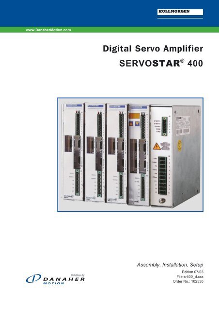
Digital Servo Amplifier SERVOSTAR 400 - BIBUS SK, sro
Digital Servo Amplifier SERVOSTAR 400 - BIBUS SK, sro
Digital Servo Amplifier SERVOSTAR 400 - BIBUS SK, sro

Create successful ePaper yourself
Turn your PDF publications into a flip-book with our unique Google optimized e-Paper software.
www.DanaherMotion.com<br />
<strong>Digital</strong> <strong>Servo</strong> <strong>Amplifier</strong><br />
<strong>SERVOSTAR</strong> ® <strong>400</strong><br />
Assembly, Installation, Setup<br />
Edition 07/03<br />
File sr<strong>400</strong>_d.xxx<br />
Order No.: 102530
Previous editions<br />
Edition Comments<br />
10/01 First edition<br />
02/02 new layout<br />
07/03 new layout, technical data adapted to new hardware, equipment matching removed<br />
PC-AT is a registered trademark of International Business Machines Corp.<br />
MS-DOS is a registered trademark of Microsoft Corp.<br />
WINDOWS is a registered trademark of Microsoft Corp.<br />
HIPERFACE is a registered trademark of Max Stegmann GmbH<br />
EnDat is a registered trademark of Dr.Johannes Heidenhain GmbH<br />
<strong>SERVOSTAR</strong> is a registered trademark of Kollmorgen Corporation<br />
Technical changes to improve the performance of the equipment may be made without notice !<br />
Printed in the Federal Republic of Germany<br />
All rights reserved. No part of this work may be reproduced in any form (by printing, photocopying, microfilm or any other<br />
method) or processed, copied or distributed by electronic means without the written permission of Danaher Motion.
Kollmorgen 07/03 Contents<br />
Page<br />
Contents . . . . . . . . . . . . . . . . . . . . . . . . . . . . . . . . . . . . . . . . . . . . . . . . . . . . . . . . . . . 3<br />
Safety Instructions . . . . . . . . . . . . . . . . . . . . . . . . . . . . . . . . . . . . . . . . . . . . . . . . . . 5<br />
European Directives and Standards. . . . . . . . . . . . . . . . . . . . . . . . . . . . . . . . . . . . . 6<br />
-Conformity . . . . . . . . . . . . . . . . . . . . . . . . . . . . . . . . . . . . . . . . . . . . . . . . . . . . . . 6<br />
Abbreviations and Symbols . . . . . . . . . . . . . . . . . . . . . . . . . . . . . . . . . . . . . . . . . . . 7<br />
1 General<br />
1.1 About this manual ...................................................................................9<br />
1.2 Use as directed. ...................................................................................10<br />
1.3 Nameplate .......................................................................................11<br />
1.4 Equipment description ..............................................................................11<br />
1.4.1 Package as supplied ..........................................................................11<br />
1.4.2 <strong>Digital</strong> servo amplifiers in the series <strong>SERVOSTAR</strong> <strong>400</strong> ...............................................12<br />
1.4.3 Operation directly from the supply. ...............................................................12<br />
1.4.4 <strong>Digital</strong> servo amplifier concept ..................................................................13<br />
1.5 Block diagram .....................................................................................15<br />
1.6 Components of a servo system .......................................................................16<br />
1.7 Technical data for <strong>SERVOSTAR</strong> <strong>400</strong> ...................................................................17<br />
1.7.1 External fusing. ..............................................................................18<br />
1.7.2 Permissible ambient conditions, ventilation, mounting position .........................................18<br />
1.7.3 Conductor cross-sections ......................................................................18<br />
1.7.4 Recommended tightening torques ...............................................................18<br />
1.7.5 LED display .................................................................................19<br />
1.8 Grounding system. .................................................................................19<br />
1.9 Motor holding brake conrol ...........................................................................19<br />
1.10 Regen circuit. .....................................................................................20<br />
1.11 Switch-on/-off behaviour .............................................................................21<br />
1.11.1 Stop function as per EN 60204 (VDE 0113) ........................................................21<br />
1.11.2 Emergency stop methods ......................................................................22<br />
2 Installation<br />
2.1 Important notes. ...................................................................................23<br />
2.2 Mounting .........................................................................................24<br />
2.2.1 Dimensions <strong>SERVOSTAR</strong> <strong>400</strong> ..................................................................25<br />
2.3 Wiring ...........................................................................................26<br />
2.3.1 Wiring diagram <strong>SERVOSTAR</strong> <strong>400</strong>M .............................................................28<br />
2.3.2 Wiring diagram <strong>SERVOSTAR</strong> <strong>400</strong>A ..............................................................29<br />
2.3.3 Example of connections for multi-axis system ......................................................30<br />
2.3.4 Connector assignments <strong>SERVOSTAR</strong> <strong>400</strong> ........................................................31<br />
2.3.5 Connection techniques ........................................................................32<br />
2.3.5.1 Shield connection on the front panel ..........................................................32<br />
2.3.5.2 Technical data of connecting cables ..........................................................33<br />
2.4 Setup software ....................................................................................35<br />
2.4.1 General ....................................................................................35<br />
2.4.1.1 Use as directed ..........................................................................35<br />
2.4.1.2 Software description ......................................................................35<br />
2.4.1.3 Hardware requirements ....................................................................36<br />
2.4.1.4 Operating systems. .......................................................................36<br />
2.4.2 Installation under WINDOWS 95 / 98 / 2000 / ME / NT / XP ............................................36<br />
<strong>SERVOSTAR</strong> ® <strong>400</strong> Installation manual 3
Contents 07/03 Kollmorgen<br />
Page<br />
3 Interfaces<br />
3.1 Supply voltage (master only) .........................................................................37<br />
3.1.1 Supply connection (X0) for 3-phase supplies .......................................................37<br />
3.1.2 Supply connection (X0) for single-phase supplies ...................................................37<br />
3.1.3 24V auxiliary voltage (X0) ......................................................................38<br />
3.1.4 DC-link/DC-bus (X0) ..........................................................................38<br />
3.2 Motor connection with brake (X6) ......................................................................38<br />
3.3 External ballast resistor (X0)(master only) ...............................................................39<br />
3.4 Feedback ........................................................................................39<br />
3.4.1 Resolver connection (X5) ......................................................................39<br />
3.4.2 Encoder connection (X2). ......................................................................40<br />
3.5 Control and monitoring signals ........................................................................41<br />
3.5.1 Analog setpoint input (X3) ......................................................................41<br />
3.5.2 <strong>Digital</strong> control inputs (X3) ......................................................................42<br />
3.5.3 <strong>Digital</strong> control outputs (X3) .....................................................................43<br />
3.5.4 <strong>Digital</strong> control signals on the PSU (X1) ............................................................44<br />
3.6 Encoder emulations ................................................................................45<br />
3.6.1 Incremntal encoder interface (X4) ................................................................45<br />
3.6.2 SSI interface (X4) ............................................................................46<br />
3.7 RS232 interface, PC connection (X8)(master only) ........................................................47<br />
3.8 Interface for stepper motor controls (pulse/direction) .......................................................48<br />
3.8.1 Connection of stepper motor controls with 5V signal level (X4) .........................................49<br />
3.8.2 Connection of stepper motor controls with 24V signal level (X3) ........................................49<br />
3.9 Interface for master-slave operation, encoder control ......................................................50<br />
3.9.1 Connection to <strong>SERVOSTAR</strong> <strong>400</strong> master, 5V level (X4) ...............................................50<br />
3.9.2 Connection to encoder with 24V signal level (X3). ...................................................51<br />
3.9.3 Connection for Sin/Cos encoder (X2) .............................................................51<br />
3.10 Fieldbus connection ................................................................................52<br />
3.10.1 CANopen interface (X7) .......................................................................52<br />
3.10.2 PROFIBUS interface (X7)(option) ................................................................53<br />
3.10.3 SERCOS interface (X7)(option) .................................................................54<br />
3.10.3.1 Light emitting diodes (LEDs) ................................................................54<br />
3.10.3.2 Connection diagram. ......................................................................54<br />
4 Commissioning<br />
4.1 Important notes. ...................................................................................55<br />
4.2 Parameterization. ..................................................................................57<br />
4.2.1 Multi-axis systems ............................................................................57<br />
4.2.2 Key pad controls and status displays .............................................................58<br />
4.2.2.1 Operating ...............................................................................58<br />
4.2.2.2 Status display on the axis module ............................................................58<br />
4.2.2.3 Status display on the master ................................................................59<br />
4.3 Error messages ...................................................................................60<br />
4.4 Warning messages .................................................................................61<br />
5 Accessories<br />
5.1 External PSU 24V DC / 5A ...........................................................................63<br />
5.2 External PSU 24V DC / 20A ..........................................................................64<br />
5.3 External ballast resistor BARxxx. ......................................................................65<br />
5.4 Add-on fan .......................................................................................66<br />
6 Appendix<br />
6.1 Transport, storage, maintenace, disposal ...............................................................67<br />
6.2 Fault-finding ......................................................................................68<br />
6.3 Glossary .........................................................................................70<br />
6.4 Index ............................................................................................72<br />
4 <strong>SERVOSTAR</strong> ® <strong>400</strong> Installation manual
Kollmorgen 07/03 Safety Instructions<br />
Safety Instructions<br />
�<br />
Only properly qualified personnel are permitted to carry out activities such<br />
as transport, installation, commissioning and maintenance. Properly<br />
qualified persons are those who are familiar with the transport, assembly,<br />
installation, commissioning and operation of the product, and who have the<br />
appropriate qualifications for their job. The qualified personnel must know<br />
and observe the following standards and regulations:<br />
IEC 364 and CENELEC HD 384 or DIN VDE 0100<br />
IEC Report 664 or DIN VDE 0110<br />
national accident prevention regulations or BGV A2<br />
� Read this documentation before carrying out the installation and<br />
commissioning. Incorrect handling of the servo amplifier can lead to<br />
personal injury or material damage. It is vital that you keep to the technical<br />
data and information on connection requirements (nameplate and<br />
documentation).<br />
�<br />
�<br />
�<br />
�<br />
�<br />
�<br />
�<br />
The manufacturer of the machine must produce a hazard analysis for the<br />
machine and take appropriate measures to ensure that unforeseen<br />
movements do not result in personal injury or material damage.<br />
The servo amplifiers contain electrostatically sensitive components which<br />
may be damaged by incorrect handling. Discharge your body before<br />
touching the servo amplifier. Avoid contact with highly insulating materials<br />
(artificial fabrics, plastic film etc.). Place the servo amplifier on a conductive<br />
surface.<br />
Do not open the equipment. Keep all covers and cabinet doors closed during<br />
operation. Otherwise, there are deadly hazards, with the possibility of death,<br />
severe injury or material damage.<br />
During operation, servo amplifiers may have uncovered live components,<br />
depending on their level of enclosure protection. Control and power<br />
connections may be live, even though the motor is not rotating.<br />
<strong>Servo</strong> amplifiers may have hot surfaces during operation. Since the front<br />
panel is used for cooling, it can reach temperatures above 80°C.<br />
Never undo any electrical connections to the servo amplifier while it is live.<br />
There is a danger of electrical arcing with damage to contacts and personal<br />
injury.<br />
Wait at least five minutes after disconnecting the servo amplifier from the<br />
main supply power before touching potentially live sections of the<br />
equipment (e.g. contacts) or undoing any connections. Capacitors can still<br />
have dangerous voltages present up to five minutes after switching off the<br />
supply power. To be sure, measure the voltage in the DC-link circuit and wait<br />
until it has fallen below 40V.<br />
<strong>SERVOSTAR</strong> ® <strong>400</strong> Installation manual 5
Directives and Standards 07/03 Kollmorgen<br />
European Directives and Standards<br />
<strong>Servo</strong> amplifiers are components that are intended to be incorporated into electrical plant and machines for industrial<br />
use.<br />
When the servoamplifiers are built into machines or plant, the intended operation of the amplifier is forbidden<br />
until it has been established that the machine or plant fulfills the requirements of the EC Machinery Directive<br />
98/37/EG and the EC Directive on EMC (89/336/EEC).<br />
To fulfill the EC Machinery directive (98/37/EG), the following standards have to be applied:<br />
EN 60204-1 (Safety and electrical equipment of machines)<br />
EN 292 (Safety of machines)<br />
The manufacturer of the machine must produce a hazard analysis for the machine and take appropriate<br />
measures to ensure that unforeseen movements do not result in personal injury or material damage.<br />
To fulfill the Low Voltage Directive 73/23/EEC, the following standards have to be applied:<br />
EN 60204-1 (Safety and electrical equipment of machines)<br />
EN 50178 (Equipment of high voltage plant with electronic devices)<br />
EN 60439-1 (Low-voltage switchgear and controlgear assemblies)<br />
To fulfill the EC EMC regulations (89/336/EEC), the following standards have to be applied:<br />
EN 61000-6-1 or EN 61000-6-2 (noise immunity within the domestic range/industrial range)<br />
EN 61000-6-3 or EN 61000-6-4 (noise emission within the domestic range/industrial range)<br />
The manufacturer of the machine or plant is responsible for ensuring that they meet the limits required by the<br />
EMC regulations. Advice on the correct installation for EMC – such as shielding, grounding, arrangement of<br />
connectors and cable routing – can be found in this documentation.<br />
The machine / plant manufacturer must examine whether with its machine / plant still further or other<br />
standards or EEC guidelines are to be used.<br />
Conformity<br />
Conformity with the EC Directive on EMC 89/336/EEC and the Low Voltage Directive 73/23/EEC is mandatory<br />
for servoamplifiers supplied within the European Union.<br />
To fulfill the EMC directive, the standard EN 61800-3 is applied.<br />
In the reference to noise immunity the servoamplifier fulfills the requirement to the category second environment<br />
(industrial environment).<br />
For the range of the noise emission the rvo amplifier fulfills the requirement to a product of the category reduced<br />
availability.<br />
Warning!<br />
This is a product with reduced availability according to IEC 61800-3. This product can cause interferences<br />
within domestic range; if required you must accomplish appropriate measures.<br />
The servo amplifiers have been tested by an authorized testing laboratory in a defined configuration with the<br />
system components which are described in this documentation. Any divergence from the configuration and installation<br />
described in this documentation means that you will be responsible for carrying out new measurements<br />
to ensure that the regulatory requirements are fulfilled.<br />
To fulfill the Low Voltage Directive, the standard EN 50178 has to be applied.<br />
6 <strong>SERVOSTAR</strong> ® <strong>400</strong> Installation manual
Kollmorgen 07/03 UL and cUL- Conformance<br />
UL and cUL- Conformance<br />
In preparation<br />
<strong>SERVOSTAR</strong> ® <strong>400</strong> Installation manual 7
Abbreviations and Symbols 07/03 Kollmorgen<br />
Abbreviations used in this Manual<br />
The abbreviations used in this manual are explained in the table below.<br />
Abbrev. Meaning<br />
AGND Analog ground<br />
BTB/RTO Ready to operate<br />
CAN Fieldbus (CANopen)<br />
CE Communité Europeenne (=EC)<br />
CLK Clock signal<br />
COM Serial interface for a PC-AT<br />
DGND <strong>Digital</strong> ground<br />
DIN Deutsches Institut für Normung<br />
Disk Magnetic storage (diskette, hard disk)<br />
EEPROM Electrically erasable memory<br />
EMC Electromagnetic compatibility<br />
EMI Elektromagnetic interference<br />
EN European standard<br />
ESD Electrostatic discharge<br />
IEC International Electrotechnical Commission<br />
IGBT Insulated gate bipolar transistor<br />
INC Incremental Interface<br />
ISO International Standardization Organization<br />
LED Light-emitting diode<br />
MB Megabyte<br />
MS-DOS Operating system for PC-AT<br />
Symbols used in this Manual<br />
danger to personnel<br />
from electricity<br />
and its effects<br />
general warning<br />
general instructions<br />
mechanical hazard<br />
� p. see Page (cross-reference) � special emphasis<br />
Keys on the master:<br />
press once : move up one menu item, increase number by one<br />
press twice in rapid succession : increase number by ten<br />
press once : move down one menu item, decrease number by one<br />
press twice in rapid succession : decrease number by ten<br />
hold right key pressed, and then press left key as well :<br />
to enter number, Return function<br />
�<br />
�<br />
� �<br />
Abbrev. Meaning<br />
NI Zero pulse<br />
NSTOP Limit-switch input, rot. dir. CCW (left)<br />
PC-AT Personal Computer with 80x86 processor<br />
PELV Protected low voltage<br />
PLC Programmable logic controller<br />
PSTOP Limit-switch input, rot. dir. CW (right)<br />
PWM Pulse-width modulation<br />
RAM Volatile memory<br />
RBallast Ballast (regen) resistor<br />
RBext External ballast (regen) resistor<br />
RBint Internal ballast (regen) resistor<br />
RES Resolver<br />
ROD 426 A quad B Encoder<br />
SRAM Static RAM<br />
SSI Synchronous serial interface<br />
SW/SETP. Setpoint<br />
UL Underwriter Laboratory<br />
V AC AC voltage<br />
V DC DC voltage<br />
VDE Verein deutscher Elektrotechniker<br />
8 <strong>SERVOSTAR</strong> ® <strong>400</strong> Installation manual
Kollmorgen 07/03 General<br />
1 General<br />
1.1 About this manual<br />
This manual describes the digital servo amplifiers of the <strong>SERVOSTAR</strong> <strong>400</strong> series.<br />
In this manual you can find information about:<br />
� Technical data of the servo amplifiers Chapter I<br />
� Assembly / installation of the servo amplifiers Chapter II<br />
� Interfaces Chapter III<br />
� Commissioning the servo amplifiers Chapter IV<br />
� Accessories for the servo amplifiers Chapter V<br />
� Transport, storage, maintenance, disposal Chapter VI<br />
A more detailed description of the field bus interfaces and the digital connection to automation systems<br />
can be found on the accompanying CD-ROM in PDF format (system requirements: WIND-<br />
OWS 95 or higher, Internet browser, Acrobat Reader 4.0 or higher) in English, German, French and<br />
Italian versions.<br />
You can print out this documentation on any standard printer. A printed copy of the documentation<br />
is available from us at extra cost.<br />
This manual makes the following demands on qualified personnel :<br />
Transport: only by personnel with knowledge of handling electrostatically<br />
sensitive components.<br />
Installation: only by electrically qualified personnel<br />
Commissioning: only by qualified personnel with extensive knowledge of electrical<br />
engineering / drive technology<br />
<strong>SERVOSTAR</strong> ® <strong>400</strong> Installation manual 9
General 07/03 Kollmorgen<br />
1.2 Use as directed<br />
The servo amplifiers are components which are built into electrical equipment or machines, and can<br />
only be commissioned as integral components of such equipment.<br />
The manufacturer of the machine must produce a hazard analysis for the machine and<br />
take appropriate measures to ensure that unforeseen movements do not result in personal<br />
injury or material damage.<br />
Use the servo amplifiers only on the following types of supply:<br />
1 x 115V AC (only <strong>SERVOSTAR</strong> 40xM, unearthed operation is permissible)<br />
3 x 115V AC (only <strong>SERVOSTAR</strong> 40xM, unearthed operation is permissible)<br />
1 x 230V AC (only <strong>SERVOSTAR</strong> 40xM, unearthed operation is permissible)<br />
3 x 230V AC (all types, unearthed operation is permissible)<br />
3 x <strong>400</strong>V AC (only <strong>SERVOSTAR</strong> 44xM, TN-system or TT-system with earthed<br />
neutral point, max. 5000A symmetrical rated current)<br />
If the servo amplifiers are used in residential areas, or in business or commercial premises, then<br />
additional filter measures must be implemented by the user.<br />
The <strong>SERVOSTAR</strong> <strong>400</strong> family of servo amplifiers is only intended to drive specific brushless synchronous<br />
servomotors with closed-loop control of torque, speed and/or position. The rated voltage<br />
of the motors must be at least as high as the DC-link voltage of the servo amplifier.<br />
The servo amplifiers may only be operated in a closed switchgear cabinet, taking into account the<br />
ambient conditions defined on Page 18. Ventilation or cooling measures may be required to keep<br />
the temperature below 45°C.<br />
Use only copper-cored cables for wiring. The conductor cross-sections can be taken from the European<br />
standard EN 60204 (or Table 310-16 of NEC for 60°C or 75°C in the column for AWG<br />
cross-sections).<br />
We can only guarantee that the system will conform to the standards cited on Page 6 if the components<br />
used are exclusively those supplied by us (servo amplifier, motor, cables etc.).<br />
10 <strong>SERVOSTAR</strong> ® <strong>400</strong> Installation manual
Kollmorgen 07/03 General<br />
1.3 Nameplate<br />
The nameplate depicted below is attached to the side of the servo amplifier.<br />
The information described below is printed in the individual fields.<br />
<strong>Servo</strong> amplifier type<br />
Danaher Motion GmbH & Co. KG<br />
Wacholderstr. 40-42<br />
D-40489 Düsseldorf<br />
www.DanaherMotion.de<br />
Typenbezeichnung<br />
Spannungsversorgung<br />
Electrical supply,<br />
installed load<br />
1.4 Equipment description<br />
1.4.1 Package as supplied<br />
Customer Service<br />
Europe Tel. +49 (0)203 / 99790<br />
Italy Tel. + 39 (0) 362 / 594260<br />
North America Tel. + 1 ( 800) 777-3786<br />
Model Number Ser. Nr<br />
Ser. No. Bemerkung<br />
Power Supply<br />
Serial number<br />
Nennstrom<br />
Output current<br />
in S1 operation<br />
If you order a <strong>SERVOSTAR</strong> <strong>400</strong> series amplifier from us, you will receive:<br />
— <strong>SERVOSTAR</strong> 4xxM (master)<br />
— Mating connectors for X0, X1, X3<br />
— Protective cover for the axis-side (required only once per system)<br />
— Assembly and Installation Instructions<br />
— Setup software DRIVE.EXE and online documentation on CD-ROM<br />
alternatively<br />
— <strong>SERVOSTAR</strong> 4xxA (axis module)<br />
— Mating connector for X3<br />
— Short-form instructions<br />
The mating SubD connectors are not part of the package supplied!<br />
Accessories: (must be ordered separately if required)<br />
Nom. Current Schutzart<br />
Instrument code<br />
— Electrical add-on fan (for max. 2 axes, required for <strong>SERVOSTAR</strong> 4x6)<br />
— Synchronous servomotor (linear or rotary)<br />
— Motor lead (pre-assembled), or motor cable as cut-off length + loose connectors<br />
(motor- and amplifier-side)<br />
— Feedback cable (pre-assembled, see also App. Report “Cables & Connectors”) or<br />
Both feedback connectors, loose with feedback cable as cut-off length<br />
— External regen resistor (� p.65)<br />
— Communication cable to PC(� p.45) for parameterizing the master and any<br />
attached axis modules<br />
— Power cable, control cables, fieldbus cables (as lengths)<br />
Comment<br />
Encl.Rating<br />
Enclosure rating<br />
<strong>SERVOSTAR</strong> ® <strong>400</strong> Installation manual 11
General 07/03 Kollmorgen<br />
1.4.2 <strong>Digital</strong> servo amplifiers in the series <strong>SERVOSTAR</strong> <strong>400</strong><br />
Standard version<br />
� 2 supply voltage versions: <strong>SERVOSTAR</strong> 40xM up to 3x230VAC and<br />
<strong>SERVOSTAR</strong> 44xM up to 3x<strong>400</strong>VAC<br />
� one size for the master and axis modules each, see Page 25<br />
� shield connection directly on the servo amplifier<br />
� analog input<br />
� fieldbus interface is integrated<br />
(standard: CANopen for integration into CAN bus systems)<br />
� RS232 is integrated<br />
� pulse-direction interface is integrated<br />
Options<br />
� PROFIBUS DP interface instead of CANopen, see page 53<br />
� SERCOS interface instead of CANopen, see page 54<br />
Open architecture<br />
� open hardware and software architecture<br />
� macro language and compiler are integrated<br />
1.4.3 Operation directly from the supply<br />
Supply power (master only)<br />
� operation directly from electrical supply:<br />
1 x 115V AC (<strong>SERVOSTAR</strong> 40xM only, unearthed operation is permitted)<br />
3 x 115V AC (<strong>SERVOSTAR</strong> 40xM only, unearthed operation is permitted)<br />
1 x 230V AC (<strong>SERVOSTAR</strong> 40xM only, unearthed operation is permissible)<br />
3 x 230V AC (all types, unearthed operation is permissible)<br />
3 x <strong>400</strong>V AC (<strong>SERVOSTAR</strong> 44xM only, TN-system or TT-system with<br />
earthed neutral point, max. 5000A sym. rated current)<br />
� fusing (e.g. fusible cutout) provided by the user<br />
Auxiliary voltage 24V DC<br />
� electrically isolated via an external 24V DC PSU, e.g. with isolating transformer<br />
Power input filter<br />
� interference suppression filter for the supply input (for reduced availability according to<br />
EN61800-3) is integrated<br />
� interference suppression filter for the 24V auxiliary supply (for general availability according<br />
to EN 61800-3) is integrated<br />
12 <strong>SERVOSTAR</strong> ® <strong>400</strong> Installation manual
Kollmorgen 07/03 General<br />
1.4.4 <strong>Digital</strong> servo amplifier concept<br />
Operation and parameter setting<br />
� with the comfortable setup software, via the serial interface of a PC to a single connection for<br />
all axes in a system<br />
� station address setting through two keys and a 3-digit LED status display on the master<br />
� fully programmable via RS232 interface<br />
Power section<br />
� power supply B6 rectifier bridge, directly off electrical supply<br />
input, integral power input filter and inrush circuit<br />
� all shielding connections directly on the amplifier<br />
� output stage IGBT module with isolated current measurement<br />
Clock frequency can be switched from 8 to 16 kHz with<br />
ASCII command (with power reduction, please contact<br />
our customer support)<br />
� regen (ballast) circuit internal regen resistor as standard,<br />
external regen resistor if required<br />
� DC-link voltage 160...310V DC for <strong>SERVOSTAR</strong> 40xM<br />
310...560V DC for <strong>SERVOSTAR</strong> 44xM<br />
160...560V DC for <strong>SERVOSTAR</strong> 4xxA<br />
Completely digital control<br />
� digital current controller (space vector pulse-width modulation, 62.5 µs)<br />
� freely programmable digital speed controller (62.5 µs or 250 µs)<br />
� integral position controller, with adaptation possibilities for every application (250 µs)<br />
� integrated pulse direction interface, for connection of a servomotor to a stepper-motor control<br />
� evaluation of the resolver signals or sine/cosine signals from a high-resolution encoder<br />
� encoder emulation (incremental ROD 426-compatible or SSI)<br />
<strong>SERVOSTAR</strong> ® <strong>400</strong> Installation manual 13
General 07/03 Kollmorgen<br />
Comfort functions<br />
� adjustable setpoint ramps<br />
� 4 programmable digital inputs<br />
(two are normally defined as limit-switch inputs)<br />
� 2 programmable digital outputs<br />
� freely programmable combinations of all digital signals<br />
Integrated safety<br />
� safe electrical separation to EN 50178 between the power input / motor connections and the<br />
signal electronics, provided by appropriate creepage distances and complete electrical isolation<br />
� Soft-start, overvoltage detection, short-circuit protection, phase-failure monitoring<br />
� temperature monitoring of servo amplifier and motor (when using our motors with our pre-assembled<br />
cables)<br />
Minimum complexity<br />
� up to 8 axes in a single system<br />
� only one power supply feed and one auxiliary voltage supply per system<br />
� all axes in a system can be parameterized through a single interface<br />
� Strongly reduced wiring expenditure by modular structure<br />
� Simple mechanical structure on DIN rails<br />
14 <strong>SERVOSTAR</strong> ® <strong>400</strong> Installation manual
Kollmorgen 07/03 General<br />
1.5 Block diagram<br />
<strong>SERVOSTAR</strong> ® <strong>400</strong> Installation manual 15
General 07/03 Kollmorgen<br />
1.6 Components of a servo system<br />
Controls / PLC<br />
<strong>SERVOSTAR</strong> <strong>400</strong><br />
motor<br />
24V supply<br />
16 <strong>SERVOSTAR</strong> ® <strong>400</strong> Installation manual<br />
fuses<br />
drive contactor<br />
PC<br />
terminals
Kollmorgen 07/03 General<br />
1.7 Technical data for <strong>SERVOSTAR</strong> <strong>400</strong><br />
max. 230VAC max. <strong>400</strong>VAC<br />
<strong>SERVOSTAR</strong> <strong>SERVOSTAR</strong><br />
Rated data DIM 403M 406M 403A 406A 443M 446M 403A 406A<br />
Rated supply voltage V~<br />
1 x 115V-10%<br />
to<br />
3 x 230V +10%<br />
—<br />
3 x 230V-10%<br />
to<br />
3 x <strong>400</strong>V +10%<br />
Max. installed load for S1 operation<br />
(in a multi-axis system)<br />
kVA 7 — 12 —<br />
Rated DC-link voltage V= 160 - 310 310 - 560<br />
Rated output current (rms value, � 3%, @ 8kHz) Arms 3 6* 3 6* 3 6* 3 6*<br />
Peak output current (max. ca. 5s, � 3%, @ 8kHz) Arms 9 12* 9 12* 9 12* 9 12*<br />
Clock frequency of output stage kHz 8 (can be switched to 16, see page 13)<br />
Technical data of regen circuit — � p.20 — � p.20 —<br />
Overvoltage switch-off threshold V 450 — 750 —<br />
maximum load inductance mH 75 40 75 40 75 40 75 40<br />
minimum load inductance mH 12 7,5 12 7,5 12 7,5 12 7,5<br />
Form factor of the output current<br />
(rated conditions and min. load inductance)<br />
— 1.01 1.01<br />
Bandwidth of subordinate current controller kHz > 1.2 > 1.2<br />
Residual voltage drop at rated current V < 5 < 5<br />
Quiescent dissipation, output stage disabled W 12 15 12 15 12 15 12 15<br />
Dissipation at rated current<br />
(without regen dissipation)<br />
Internal fusing (for external fusing � p.18)<br />
W 35 60 30 40 35 60 30 40<br />
Auxiliary supply 24V<br />
Regen resistor<br />
Inputs/outputs<br />
—<br />
—<br />
int. 20 AM<br />
electronic<br />
—<br />
int. 20 AM<br />
electronic<br />
—<br />
Analog input, 14-bit resolution V �10 �10<br />
common-mode voltage max. V �10 �10<br />
input resistance k� 20 20<br />
<strong>Digital</strong> control inputs low 0...7 / high 11...30V, 7mA low 0...7 / high 11...30V, 7mA<br />
<strong>Digital</strong> control outputs, open emitter max. 30V, 10mA max. 30V, 10mA<br />
BTB/RTO output, relay contacts<br />
V<br />
DC max. 30,<br />
AC max 42 —<br />
DC max. 30,<br />
AC max 42 —<br />
mA 500 500<br />
Auxiliary supply, electrically isolated,<br />
without brake, without fan<br />
V<br />
A<br />
20...30<br />
0.5<br />
—<br />
20...30<br />
0.5<br />
—<br />
Auxiliary supply, electrically isolated,<br />
with brake or fan (check voltage drop !)<br />
V<br />
A<br />
24<br />
(-0% +15%)<br />
2.5<br />
—<br />
24<br />
(-0% +15%)<br />
2.5<br />
—<br />
Max. output current for brake<br />
Connections<br />
A 2 2<br />
Control signals — Combicon spring terminal<br />
Power supply —<br />
Power<br />
Combicon<br />
—<br />
Power<br />
Combicon<br />
—<br />
Motor — Combicon Combicon<br />
Resolver input — SubD 9-pin (socket) SubD 9-pin (socket)<br />
Incremental encoder input — SubD 15-pin (socket) SubD 15-pin (socket)<br />
PC interface — SubD 9-pin (plug) SubD 9-pin (plug)<br />
Encoder emulation, ROD/SSI<br />
Mechanical<br />
— SubD 9-pin (plug) SubD 9-pin (plug)<br />
Weight kg 3 1.7 3 1.7<br />
Height, without connectors mm 230 267* 230 267* 230 267* 230 267*<br />
Width mm 100 50 100 50<br />
Depth, without connectors<br />
* with add-on ventilation<br />
mm 240 240 240 240<br />
<strong>SERVOSTAR</strong> ® <strong>400</strong> Installation manual 17<br />
—
General 07/03 Kollmorgen<br />
1.7.1 External fusing<br />
Fusible cutouts or similar<br />
AC feed FN1/2/3 16 A slow<br />
24V feed FH1/2 16 A slow<br />
regen resistor FB1/2 6 A slow<br />
1.7.2 Permissible ambient conditions, ventilation, mounting position<br />
Storage temp. / humidity / duration � p.65<br />
Transport temperature / humidity � p.65<br />
Supply voltage tolerances<br />
main power<br />
<strong>SERVOSTAR</strong> 40xM<br />
<strong>SERVOSTAR</strong> 44xM<br />
auxiliary supply<br />
w/o brake, w/o fan<br />
with brake or fan<br />
Ambient temperature in operation<br />
min 1x115V-10% AC / max 1x230V +10% , 50/60 Hz<br />
min 3x115V-10% AC / max 3x230V +10% , 50/60 Hz<br />
min 3x230V-10% AC / max 3x<strong>400</strong>V +10% , 50/60 Hz<br />
20 VDC ... 30 VDC<br />
24 VDC (-0% +15%)<br />
0...+45 o C at rated conditions<br />
+45...+55°C with power derating 2.5% / K<br />
Humidity in operation rel. humidity 85%, no condensation<br />
up to 1000m amsl without restrictions<br />
Site altitude<br />
1000...2500m amsl with derating<br />
1.5% / 100m<br />
Pollution level Pollution level 2 as per EN 60204 / EN 50178<br />
Enclosure rating IP 20<br />
Mounting position normally vertical � p.24<br />
Ventilation<br />
free convection for <strong>SERVOSTAR</strong>4x3,<br />
add-on fan (� p.66) required for <strong>SERVOSTAR</strong>4x6<br />
Make sure that there is adequate forced ventilation within the closed switchgear cabinet.<br />
1.7.3 Conductor cross-sections<br />
Following EN 60204-1, we recommend for single-axis systems:<br />
AC connection 4 mm², depending on the system fusing<br />
Motor cables 1 mm², shielded, capacitance
Kollmorgen 07/03 General<br />
1.7.5 LED display<br />
A 3-digit LED display indicates the amplifier status after switching on the 24V supply<br />
(� p.59). The address can be read out while it is being set on the master by using the keys.<br />
1.8 Grounding system<br />
AGND – ground reference for analog signals, internal analog ground<br />
DGND – ground reference for digital signals and auxiliary supply voltage, optically isolated<br />
The electrical isolation is indicated in the block diagram (� p.15).<br />
1.9 Motor holding brake conrol<br />
A motor holding brake (24V / max.1,5A) can be controlled directly by the servo amplifier. This<br />
function does not ensure personnel safety! The brake function must be enabled through the<br />
BRAKE parameter (on the screen page for Motor): the setting is WITH. In the diagram below you<br />
can see the timing and functional relationships between the ENABLE signal, speed setpoint, speed<br />
and braking force.<br />
During the internal ENABLE delay time of 100ms the speed setpoint of the servo amplifier is internally<br />
driven down a 10ms ramp to 0V. The brake output is switched on when 3% of the final speed<br />
is reached, at the latest after 1 second.<br />
The rise (fbrH) and fall (fbrL) times of the holding brakes that are built into the motors vary for the different<br />
types of motor (see motor manual).<br />
A description of the interface can be found on Page 38.<br />
Personnel-safe operation of the holding brake requires an additional “make” contact in the brake circuit<br />
and a spark suppressor device (e.g. a varistor) in the recommended brake circuit:<br />
<strong>SERVOSTAR</strong><br />
<strong>SERVOSTAR</strong> ® <strong>400</strong> Installation manual 19
General 07/03 Kollmorgen<br />
1.10 Regen circuit<br />
During braking with the aid of the motor, energy is fed back to the servo amplifier. This energy is<br />
converted into heat in the regen resistor (ballast resistor). The regen resistor is switched in and out<br />
by the regen circuit. The switching thresholds for the regen circuit are adjusted to suit the supply<br />
voltage with the aid of the setup software.<br />
Our customer support can help you with the calculation of the regen power which is required. A description<br />
of the interface can be found on Page 39 .<br />
Internal regen resistor 33 �<br />
External regen resistor 33 �<br />
Functional description<br />
The regen circuit starts to respond when the DC-link voltage reaches the set value.<br />
If the energy which is fed back from the motor, as an average over time or as a<br />
peak value, is higher than the preset regen power, then the servo amplifier will<br />
output the status regen power exceeded and the circuit will be switched off.<br />
At the next internal check of the DC-link voltage (after a few milliseconds) an<br />
overvoltage will be detected and the servo amplifier will be switched off, with the<br />
error message overvoltage (� p.60).<br />
The BTB/RTO contact (terminals X1/1,2) will be opened simultaneously (� p.44).<br />
Technical data: regen circuit<br />
Supply voltage Rated data DIM Value<br />
Upper switch-on threshold for regen circuit V <strong>400</strong><br />
Switch-off threshold for regen circuit V 380<br />
Continuous int. power in regen circuit (RBint) W 55<br />
3 x 230 V Continuous ext. power in circuit (RBext) max. kW 0,4<br />
Pulse power, internal (RBint max. 1s) kW 4.8<br />
Pulse power, external (RBext max. 1s) kW 4.8<br />
External regen resistor � 33<br />
Upper switch-on threshold for regen circuit V 720<br />
Switch-off threshold for regen circuit V 680<br />
Continuous int. power in regen circuit (RBint) W 80<br />
3 x <strong>400</strong> V Continuous ext. power in circuit (RBext) max. kW 0,6<br />
Pulse power, internal (RBint max. 1s) kW 16<br />
Pulse power, external (RBext max. 1s) kW 16<br />
External regen resistor � 33<br />
20 <strong>SERVOSTAR</strong> ® <strong>400</strong> Installation manual
Kollmorgen 07/03 General<br />
1.11 Switch-on/-off behaviour<br />
The diagram below illustrates the correct functional sequence for switching the servo amplifier on<br />
and off.<br />
1.11.1 Stop function as per EN 60204 (VDE 0113)<br />
If a fault occurs (� p.60), the output stage of the servo amplifier is switched off and the BTB/RTO<br />
contact is opened. In addition, a global error signal can be given out at one of the digital outputs<br />
(terminals X3/8 and X3/9) (see the Online help in the setup software, or the manual for the setup<br />
software). These signals can be used by the higher-level control to terminate the current PLC cycle<br />
or to shut down the drive (through an additional brake or similar means).<br />
Instruments with a selected Brake function use a special sequence for switching off the output stage<br />
(� p.19).<br />
The Stop functions are defined in EN 60204 (VDE 0113), Paras. 9.2.2 and 9.2.5.3.<br />
There are three categories of Stop functions:<br />
Category 0: Shut down by immediate switch-off of the supply of energy to the<br />
drive machinery (i.e. an uncontrolled shut-down)<br />
Category 1: A controlled shut-down, during which the supply of energy to the<br />
drive machinery is maintained to perform the shut-down, and where<br />
the supply is only interrupted when standstill has been reached<br />
Category 2: A controlled shut-down, where the supply of energy to the drive<br />
machinery is maintained<br />
Every machine must be equipped with a Stop function to Category 0.<br />
Categories 1 and/or 2 must be provided if the safety or functional requirements of the machine<br />
make this necessary.<br />
<strong>SERVOSTAR</strong> ® <strong>400</strong> Installation manual 21
General 07/03 Kollmorgen<br />
1.11.2 Emergency stop methods<br />
The Emergency Stop function is defined in EN 60204 (VDE 0113), Para. 9.2.5.4.<br />
Implementation of the Emergency Stop function :<br />
You can find wiring recommendations in our application note<br />
“Stop and Emergency Stop functions with <strong>SERVOSTAR</strong>”<br />
Category 0:<br />
The amplifier is disabled, the electrical supply is disconnected.<br />
The drive must be held by an electromagnetical clamping device (brake).<br />
In multi-axis systems (several <strong>SERVOSTAR</strong> <strong>400</strong>-systems or combinations of<br />
<strong>SERVOSTAR</strong> <strong>400</strong> and <strong>SERVOSTAR</strong> 600) using a coupled DC-link (= DC bus) the motor<br />
cable must also be disconnected by a changeover switch (a contactor, such as Siemens<br />
type 3RT1516-1BB40) and short-circuited by resistors wired in a star configuration.<br />
Category 1:<br />
If hazardous conditions can result from an Emergency Stop disconnection,<br />
because of an unbraked run-down, then the drive can be switched off by a<br />
controlled shut-down.<br />
Stop Category 1 permits electromotive braking with a switch-off when zero<br />
speed has been reached.<br />
Safe shut-down can be achieved if the disappearance of the supply power is not<br />
evaluated as a fault, but the control system takes on the task of disabling the<br />
amplifier.<br />
In the normal situation only the main supply power is switched off in a safe<br />
manner. The 24V auxiliary supply remains switched on.<br />
22 <strong>SERVOSTAR</strong> ® <strong>400</strong> Installation manual
Kollmorgen 07/03 Installation<br />
2 Installation<br />
2.1 Important notes<br />
� Protect the servo amplifier from impermissible stresses. In particular, do not let any components<br />
become bent or any insulation distances altered during transport and handling. Avoid<br />
contact with electronic components and contacts.<br />
� Check the combination of servo amplifier and motor (� p.72). Compare the rated voltage<br />
and current of the units. Carry out the wiring according to the instructions on Page 26.<br />
� Make sure that the maximum permissible rated voltage at the terminals for L1, L2, L3 and<br />
+RBext, –DC is not exceeded by more than 10%, even in the most unfavourable conditions<br />
(see EN 60204-1 Section 4.3.1). An excessive voltage on these terminals can lead to destruction<br />
of the regen circuit and the servo amplifier.<br />
Use the <strong>SERVOSTAR</strong> 44x only on an earthed 3-phase supply system. Use the amplifier only<br />
to drive a synchronous servomotor.<br />
� The fusing of the AC supply input and the 24V supply is installed by the user (� p.18).<br />
� Take care that the servo amplifier and motor are properly earthed. Do not use painted<br />
(non-conductive) mounting plates.<br />
� Route power and control cables separately. We recommend a separation of at least 20 cm.<br />
This improves the interference immunity required by EMC regulations. If a motor power cable<br />
is used which includes cores for brake control, the brake control cores must be separately<br />
shielded.<br />
Earth the shielding at both ends (� p.28).<br />
� Install all heavy-current cables with an adequate cross-section, as per EN 60204-1<br />
(� p.18).<br />
� Wire the BTB/RTO contact in series into the safety circuit of the installation.<br />
Only in this way is the monitoring of the servo amplifier assured.<br />
� Install all shielding with large area (low impedance) connections, with metallised connector<br />
housings or shield connection clamps where possible.<br />
Notes on connection techniques can be found on Page 32 and the Application Note “Cables<br />
& Connectors”.<br />
� Ensure that there is an adequate flow of cool, filtered air into the bottom of the switchgear<br />
cabinet. Note the conditions on Page 18 .<br />
� It is permissible to alter the servo amplifier settings by using the operator software.<br />
Any other alterations will invalidate the warranty.<br />
Caution<br />
Never disconnect the electrical connections to the servo amplifier while it is live.<br />
In unfavourable circumstances this could result in destruction of the electronics.<br />
Residual charges in the capacitors can have dangerous levels up to 300 seconds after<br />
switching off the mains supply voltage. Measure the voltage in the DC-link<br />
(+RBext/-DC) and wait until the voltage has fallen below 40V.<br />
Control and power connections can still be live, even when the motor is not rotating.<br />
<strong>SERVOSTAR</strong> ® <strong>400</strong> Installation manual 23
Installation 07/03 Kollmorgen<br />
2.2 Mounting<br />
Material: 2 mounting rails to EN60715, min. length = system width + 40mm,<br />
make sure there is a conductive connection to the mounting plate<br />
Mount the protective cover (7mm) on the left side of the system.<br />
Tools required: Screwdriver with approx. 5 mm blade width<br />
60715<br />
<strong>SERVOSTAR</strong> <strong>400</strong><br />
24 <strong>SERVOSTAR</strong> ® <strong>400</strong> Installation manual
Kollmorgen 07/03 Installation<br />
2.2.1 Dimensions <strong>SERVOSTAR</strong> <strong>400</strong><br />
<strong>SERVOSTAR</strong> <strong>400</strong>M<br />
<strong>SERVOSTAR</strong> <strong>400</strong>A<br />
<strong>SERVOSTAR</strong> ® <strong>400</strong> Installation manual 25
Installation 07/03 Kollmorgen<br />
2.3 Wiring<br />
Only professional staff who are qualified in electrical engineering are allowed to install the<br />
servo amplifier.<br />
The installation procedure is described as an example. A different procedure may be appropriate or<br />
necessary, depending on the application of the equipment.<br />
We provide further know-how through training courses (on request).<br />
Caution !<br />
Only install and wire up the equipment when it is not live, i.e. when neither the mains<br />
power supply nor the 24 V auxiliary voltage nor the operating voltages of any other<br />
connected equipment is switched on.<br />
Take care that the cabinet is safely disconnected (with a lock-out, warning signs etc.).<br />
The individual voltages will be switched on for the first time during commissioning.<br />
Note !<br />
The ground symbol �, which you will find in all the wiring diagrams, indicates that<br />
you must take care to provide an electrically conductive connection with the largest<br />
possible area between the unit indicated and the mounting plate in the switchgear cabinet.<br />
This connection is for the effective grounding of HF interference, and must not be<br />
confused with the PE symbol � (protective earth to EN 60204).<br />
Use the following wiring and connection diagrams :<br />
— Power and control connections : Page 28<br />
— Multiaxis systems : Page 30<br />
— Resolver : Page 39<br />
— High-resolution encoder : Page 40<br />
— Encoder emulation ROD : Page 45<br />
— Encoder emulation SSI : Page 46<br />
— RS232 / PC : Page 45<br />
— Pulse/direction interface : Page 48<br />
— Master/slave interface : Page 50<br />
— CAN interface : Page 52<br />
— PROFIBUS interface : Page 53<br />
— SERCOS interface : Page 54<br />
26 <strong>SERVOSTAR</strong> ® <strong>400</strong> Installation manual
Kollmorgen 07/03 Installation<br />
The following notes should assist you to carry out the installation in a sensible sequence, without<br />
overlooking anything important.<br />
Site<br />
Ventilation<br />
Mounting<br />
Cable selection<br />
Grounding,<br />
Shielding<br />
Wiring<br />
Check<br />
In a closed switchgear cabinet. Observe Page 18 .<br />
The site must be free from conductive or corrosive materials.<br />
For the mounting position within the cabinet � p.24<br />
Check that the ventilation of the servo amplifier is unimpeded and keep<br />
within the permitted ambient temperature � p.18 .<br />
Keep the required space clear above and below the servo amplifier<br />
� p.24.<br />
Mount the servo amplifier on mounting rails (DIN-rails) on the conductive,<br />
earthed mounting plate in the cabinet.<br />
Select cables according to EN 60204-1, � p.18<br />
EMC-conform shielding and grounding (� p.28)<br />
Earth the mounting plate, motor housing and CNC-GND of the controls.Notes<br />
on connection techniques are on Page 32<br />
— Route power leads separately from control cables<br />
— Wire the BTB/RTO contact in series into the safety loop of the<br />
installation<br />
— Connect the digital control inputs to the servo amplifier<br />
— Connect up AGND<br />
— Connect the analog setpoint, if required<br />
— Connect the feedback unit (resolver or encoder)<br />
— If required, connect the encoder emulation<br />
— If required, connect the fieldbus<br />
— Connect the motor cable<br />
— Connect shielding to EMC connectors at the motor end, and the<br />
— shielding lug at the amplifier end<br />
— Connect motor-holding brake, with shielding to EMC connector at<br />
— the motor end, and to shielding lug at the amplifier end<br />
— If required, connect the external regen resistor (with fusing)<br />
— Connect the auxiliary supply<br />
— (maximum permissible voltages � p.18)<br />
— Connect main power supply<br />
— (maximum permissible voltages � p.18)<br />
— Connect PC (� p.45).<br />
Make a final check of the wiring carried out against the wiring diagrams<br />
that have been used<br />
<strong>SERVOSTAR</strong> ® <strong>400</strong> Installation manual 27
Installation 07/03 Kollmorgen<br />
2.3.1 Wiring diagram <strong>SERVOSTAR</strong> <strong>400</strong>M<br />
Follow the safety instructions (� p.5)<br />
and the use as directed (� p.10) !<br />
� p.40<br />
� p.39<br />
� p.50<br />
� p.45<br />
<strong>SERVOSTAR</strong> <strong>400</strong>M<br />
� p.38<br />
� p.52<br />
� p.41<br />
� p.42<br />
� p.43<br />
� p.44<br />
� p.38<br />
� p.39<br />
� p.37<br />
28 <strong>SERVOSTAR</strong> ® <strong>400</strong> Installation manual
Kollmorgen 07/03 Installation<br />
2.3.2 Wiring diagram <strong>SERVOSTAR</strong> <strong>400</strong>A<br />
Follow the safety instructions (� p.5)<br />
and the use as directed (� p.10) !<br />
� p.40<br />
� p.39<br />
<strong>SERVOSTAR</strong> <strong>400</strong>A<br />
� p.38<br />
� p.50<br />
� p.52<br />
� p.41<br />
� p.42<br />
� p.43<br />
<strong>SERVOSTAR</strong> ® <strong>400</strong> Installation manual 29
Installation 07/03 Kollmorgen<br />
2.3.3 Example of connections for multi-axis system<br />
Follow the safety instructions (� p.5)<br />
and the use as directed (� p.10) !<br />
<strong>SERVOSTAR</strong> <strong>400</strong>M<br />
<strong>SERVOSTAR</strong> <strong>400</strong>A<br />
<strong>SERVOSTAR</strong> <strong>400</strong>A<br />
30 <strong>SERVOSTAR</strong> ® <strong>400</strong> Installation manual<br />
M M M
Kollmorgen 07/03 Installation<br />
2.3.4 Connector assignments <strong>SERVOSTAR</strong> <strong>400</strong><br />
<strong>SERVOSTAR</strong> ® <strong>400</strong> Installation manual 31
Installation 07/03 Kollmorgen<br />
2.3.5 Connection techniques<br />
Please consult our application note “Cables & Connectors”.<br />
2.3.5.1 Shield connection on the front panel<br />
<strong>SERVOSTAR</strong> <strong>400</strong><br />
<strong>SERVOSTAR</strong> <strong>400</strong><br />
The pre-assembled cables for<br />
<strong>SERVOSTAR</strong> <strong>400</strong> are provided<br />
with an overall metal ferrule at the<br />
amplifier end that is electrically<br />
connected to the shielding.<br />
Thread a cable tie through each slot<br />
in the shielding strip (front panel) of<br />
the servo amplifier.<br />
Tighten up the cable ties so that the<br />
shielding ferrule and the sheathing<br />
of the cable is pressed down tightly<br />
against the shielding strip.<br />
32 <strong>SERVOSTAR</strong> ® <strong>400</strong> Installation manual
Kollmorgen 07/03 Installation<br />
2.3.5.2 Technical data of connecting cables<br />
Further information on the chemical, mechanical and electrical characteristics of the cables can be<br />
obtained from our customer support.<br />
Insulation material<br />
Sheathing PUR (polyurethane, code 11Y)<br />
Core insulation PETP (polyesteraphthalate, code 12Y)<br />
Capacitance<br />
Motor cable less than 150 pF/m<br />
RES/encoder cable less than 120 pF/m<br />
Technical data<br />
— The brackets in the cable designation indicate the shielding.<br />
— All cables are suitable for use as trailing cables.<br />
— The technical data refer to the use as moveable cables.<br />
operating life : 1 million bending cycles<br />
— The permissible operating temperature range is from -30°C to +80°C.<br />
— All cables are colour-coded according to IEC 757.<br />
Cores<br />
[mm²]<br />
External diameter<br />
[mm]<br />
Bending radius<br />
[mm]<br />
Remarks<br />
(4x1.0) 10 100 Motor cable<br />
(4x1.0+(2x0.75)) 10.5 100<br />
Motor cable with extra cores<br />
for controls<br />
(4x2x0.25) 6.9 60<br />
(7x2x0.25) 9.9 80 twisted pairs<br />
(10x2x0.14) 8.8 80<br />
<strong>SERVOSTAR</strong> ® <strong>400</strong> Installation manual 33
Installation 07/03 Kollmorgen<br />
This page has been deliberately left blank.<br />
34 <strong>SERVOSTAR</strong> ® <strong>400</strong> Installation manual
Kollmorgen 07/03 Installation<br />
2.4 Setup software<br />
2.4.1 General<br />
This chapter describes the installation of the setup software DRIVE.EXE for the <strong>SERVOSTAR</strong> <strong>400</strong><br />
digital servo amplifiers.<br />
We offer training and familiarization courses on request.<br />
2.4.1.1 Use as directed<br />
The operator software is intended to be used for altering and storing the operating parameters for<br />
the <strong>SERVOSTAR</strong> <strong>400</strong> series of servo amplifiers. The attached servo amplifier is commissioned with<br />
the assistance of the software - during this process the drive can be controlled directly by the service<br />
functions.<br />
Only professional personnel who have the relevant expertise described on Page 9 are<br />
permitted to carry out online parameter setting for a drive which is running.<br />
Sets of data which are stored on data media are not safe against unintended alteration<br />
by other persons. After loading a set of data you must therefore check all parameters<br />
thoroughly before enabling the servo amplifier.<br />
2.4.1.2 Software description<br />
The servo amplifiers must be adapted to the requirements of your installation. Usually you will not<br />
have to carry out this parameter setting yourself on the amplifier, but on a PC, with the assistance of<br />
the operator software. The PC is connected to the servo amplifier by a null-modem (serial) cable.<br />
The setup software provides the communication between the PC and <strong>SERVOSTAR</strong> <strong>400</strong>.<br />
You will find the setup software on the accompanying CD-ROM and in the download section of the<br />
Danaher Motion web appearance.<br />
With very little effort you can alter parameters and immediately observe the effect on the drive,<br />
since there is a continuous (online) connection to the amplifier. At the same time, important actual<br />
values are read out from the amplifier and displayed on the PC monitor (oscilloscope function).<br />
Any interface modules which may be built into the amplifier are automatically recognized, and the<br />
additional parameters which are required for position control or motion-block definition are made<br />
available.<br />
Sets of data can be stored on data media (archived) and loaded again. You can also print out the<br />
data sets.<br />
We provide you with motor-specific default sets of data for all the reasonable combinations of servo<br />
amplifier and motor. In most applications you will be able to use these default values to get your<br />
drive running without any problems.<br />
<strong>SERVOSTAR</strong> ® <strong>400</strong> Installation manual 35
Installation 07/03 Kollmorgen<br />
2.4.1.3 Hardware requirements<br />
The PC interface (X6, RS232) of the master is connected to a serial interface on the PC by a<br />
null-modem cable (not a null-modem link cable !) (� p.45).<br />
Connect / disconnect the interface cable only when the supply is switched off for both<br />
the PC and the servo amplifier.<br />
The interface in the servo amplifier is electrically isolated by an optocoupler, and is at the same<br />
potential as the CANopen interface.<br />
Minimum requirements for the PC:<br />
2.4.1.4 Operating systems<br />
Processor : 80486 or higher<br />
Operating system : WINDOWS 95(c) / 98 /2000 / ME, WINDOWS NT4.0 / XP<br />
Graphica adapter : Windows compatible, color<br />
Drives : Diskette drive 3.5"<br />
Hard disk (5 MB free space)<br />
CD-ROM drive<br />
Main memory : at least 8MB<br />
Interface : one free serial interface (COM1:, 2:, 3: or 4:)<br />
WINDOWS 95(c) / WINDOWS 98 / WINDOWS 2000 / WINDOWS ME / WINDOWS NT / XP<br />
DRIVE.EXE can run under WINDOWS 95c / 98 / 2000 / ME / XP or WINDOWS NT 4.0.<br />
The help system can not be used under Windows 95a and 95b.<br />
WINDOWS FOR WORKGROUPS 3.xx, DOS, OS2, Unix, Linux<br />
DRIVE.EXE does not run under WINDOWS 3.xx, DOS, OS2, Unix and Linux.<br />
Emergency operation is possible with an ASCII terminal-emulation (without user interface).<br />
Interface setting: 9600 bps, no parity, no handshake<br />
2.4.2 Installation under WINDOWS 95 / 98 / 2000 / ME / NT / XP<br />
The CD-ROM includes an installation program called SETUP.EXE that makes it easier to install the<br />
setup software on your PC.<br />
Connection to the serial interface of the PC:<br />
Connect the interface cable to a serial interface on your PC and the PC interfaces (X8) of the<br />
<strong>SERVOSTAR</strong> <strong>400</strong> (� p.45).<br />
Switch-on:<br />
Switch on your PC-AT and the monitor.<br />
After the start phase (boot-up) is finished, the Windows user-interface appears on the screen.<br />
Installation:<br />
Click on START (task bar), then on Run.<br />
Enter the program call x:\setup.exe (where x= is the drive letter for the CD drive).<br />
Click on OK and follow the instructions.<br />
Setting up the graphics card (font size)<br />
Click on the desktop with the right mouse button. The dialogue window “Properties” will appear.<br />
Select the file card “Settings”. Set the Font size to “Small Fonts”. Follow the instructions provided<br />
by the system.<br />
36 <strong>SERVOSTAR</strong> ® <strong>400</strong> Installation manual
Kollmorgen 07/03 Interfaces<br />
3 Interfaces<br />
This chapter presents all the important interfaces, divided between master and axis module. The<br />
precise location of the connectors and terminals can be seen on Page 31.<br />
3.1 Supply voltage, master only<br />
3.1.1 Supply connection (X0) for 3-phase supplies<br />
Directly to earthed supply, filter is integrated, fusing (e.g. fusible cut-outs) to be provided by the user<br />
� p.18<br />
<strong>SERVOSTAR</strong> <strong>400</strong><br />
3.1.2 Supply connection (X0) for single-phase supplies<br />
Directly to supply, filter is integrated, fusing (e.g. fusible cut-outs) to be provided by the user � p.18<br />
<strong>SERVOSTAR</strong> <strong>400</strong><br />
for <strong>SERVOSTAR</strong>40xM<br />
for <strong>SERVOSTAR</strong>44xM<br />
for <strong>SERVOSTAR</strong>40xM<br />
<strong>SERVOSTAR</strong> ® <strong>400</strong> Installation manual 37
Interfaces 07/03 Kollmorgen<br />
3.1.3 24V auxiliary voltage (X0)<br />
— Electrically isolated supply from an external 24V DC PSU, e.g. with isolating transformer<br />
— Required current rating � p.17<br />
— Integrated EMC filter for the 24V auxiliary supply<br />
<strong>SERVOSTAR</strong> <strong>400</strong><br />
3.1.4 DC-link/DC-bus (X0)<br />
Can be connected in parallel with further, identical masters (via terminals -DC and RBext).<br />
3.2 Motor connection with brake (X6)<br />
<strong>SERVOSTAR</strong> <strong>400</strong><br />
Max. admisible length of the motor cable is 25 m.<br />
38 <strong>SERVOSTAR</strong> ® <strong>400</strong> Installation manual
Kollmorgen 07/03 Interfaces<br />
3.3 External ballast resistor (X0), master only<br />
3.4 Feedback<br />
Remove the plug-on link between terminals X0/5 (-RB) and X0/4 (+Rbint).<br />
<strong>SERVOSTAR</strong> <strong>400</strong><br />
3.4.1 Resolver connection (X5)<br />
Our rotary servomotors have 2-pole hollow-shaft resolvers built in as a standard.<br />
It is possible to connect 2- to 32-pole resolvers to <strong>SERVOSTAR</strong> <strong>400</strong>.<br />
If lead lengths of more than 25m are planned, please consult our customer support.<br />
The thermostat contact in the motor is connected via the resolver cable to the <strong>SERVOSTAR</strong> <strong>400</strong><br />
and evaluated there.<br />
<strong>SERVOSTAR</strong> <strong>400</strong><br />
SubD9 12-pin round<br />
<strong>SERVOSTAR</strong> ® <strong>400</strong> Installation manual 39
Interfaces 07/03 Kollmorgen<br />
3.4.2 Encoder connection (X2)<br />
As an option, the motors can be fitted with a single-turn or multiturn sine-cosine encoder. Preferred<br />
types are the ECN1313 and EQN1325 encoders.<br />
The encoder is used by the <strong>SERVOSTAR</strong> <strong>400</strong> as a feedback device for drive tasks that require<br />
highly precise positioning or extremely smooth running.<br />
If lead lengths of more than 25m are planned, please consult our customer support.<br />
The thermostat contact in the motor is connected via the encoder cable to the <strong>SERVOSTAR</strong> <strong>400</strong><br />
and evaluated there.<br />
<strong>SERVOSTAR</strong> <strong>400</strong><br />
SubD15 17-pin round<br />
40 <strong>SERVOSTAR</strong> ® <strong>400</strong> Installation manual
Kollmorgen 07/03 Interfaces<br />
3.5 Control signals<br />
3.5.1 Analog setpoint input (X3)<br />
The servo amplifier has a programmable input for analog setpoints.<br />
AGND (X3/1) must always be joined to the CNC-GND of the controls to provide a ground reference.<br />
Technical data<br />
— Input voltage max. ± 10 V<br />
— Resolution 1.25 mV<br />
— Ground reference AGND, terminal X3/1<br />
— Input resistance 20 k�<br />
— Common mode voltage range for both inputs ± 10 V supplementary<br />
<strong>SERVOSTAR</strong> <strong>400</strong><br />
Analog input (terminals X3/2-3)<br />
Input voltage max. ± 10 V, 14-bit resolution, scalable<br />
Standard setting speed setpoint<br />
Fixing the direction of rotation<br />
Standard setting clockwise rotation of the motor shaft (looking at shaft end)<br />
with positive voltage on terminal X3/3 (+ ) against X3/2 (-)<br />
To reverse the direction of rotation you can swap the connections to terminals X3/2-3 or change the<br />
DIRECTION parameter in the SPEED screen.<br />
<strong>SERVOSTAR</strong> ® <strong>400</strong> Installation manual 41
Interfaces 07/03 Kollmorgen<br />
3.5.2 <strong>Digital</strong> control inputs (X3)<br />
All digital inputs are electrically isolated through optocouplers.<br />
Technical data<br />
— Reference ground is digital-GND (DGND, terminal X1/4,5 on the master)<br />
— The logic is dimensioned for +24V / 7mA (PLC-compatible)<br />
— H-level from +12...36V / 7mA, L-level from 0...7V /0mA<br />
<strong>SERVOSTAR</strong> <strong>400</strong><br />
You can use the digital inputs PSTOP / NSTOP / DIGITAL-IN1 and DIGITAL-IN2 to initiate pre-programmed<br />
functions that are stored in the servo amplifier.<br />
You will find a list of the pre-programmed functions in the Online Help.<br />
If an input has to be re-assigned to a pre-programmed function, then the data set must be stored in<br />
the EEPROM of the servo amplifier, and the 24V auxiliary supply for the servo amplifier must be<br />
switched off and then on again (to reset the amplifier software).<br />
Limit-switches PSTOP / NSTOP<br />
Terminals X3/6 and X3/7 are normally programmed for the connection of limit switches.<br />
If these inputs are not needed for the connection of limit switches, then they can be used for other<br />
input functions.<br />
Limit-switch positive/negative (PSTOP / NSTOP, terminals X3/6 and X3/7), high level in normal<br />
operation (fail-safe for cable break).<br />
A low signal (open) inhibits the corresponding direction of rotation, the ramp functions remain<br />
effective.<br />
DIGITAL-IN 1 / DIGITAL-IN 2<br />
You can link the digital inputs at terminals X3/4 (DIGITAL-IN 1) and X3/5 (DIGITAL-IN2) with a<br />
pre-programmed function.<br />
42 <strong>SERVOSTAR</strong> ® <strong>400</strong> Installation manual
Kollmorgen 07/03 Interfaces<br />
3.5.3 <strong>Digital</strong> control outputs (X3)<br />
Technical characteristics<br />
— Ground reference is <strong>Digital</strong>-GND (DGND, terminal X1/4,5 on the master)<br />
— Alle digital outputs are floating<br />
— DIGITAL-OUT1 and 2 : Open-collector, max. 30V DC, 10mA<br />
<strong>SERVOSTAR</strong> <strong>400</strong><br />
Programmable digital outputs DIGITAL-OUT 1/2:<br />
You can use the digital outputs DIGITAL-OUT1 (terminal X3/8) and DIGITAL-OUT2<br />
(terminal X3/9) to output messages from pre-programmed functions that are stored in the servo<br />
amplifier.<br />
A list of the pre-programmed functions can be found in the Online Help.<br />
If an input is freshly assigned to a pre-programmed function, then the data set must be stored in the<br />
EEPROM of the servo amplifier, and the 24V auxiliary supply of the servo amplifier must be switched<br />
off and on again (to reset the amplifier software).<br />
<strong>SERVOSTAR</strong> ® <strong>400</strong> Installation manual 43
Interfaces 07/03 Kollmorgen<br />
3.5.4 <strong>Digital</strong> control signals on the PSU (X1)<br />
Technical characteristics<br />
— Ground reference is <strong>Digital</strong>-GND (DGND, terminal X1/4,5)<br />
— The logic is dimensioned for +24V / 7mA (PLC-compatible)<br />
— H-level from +12...36V / 7mA, L-level from 0...7V /0mA<br />
BTB/RTO: Relay output, max. 30V DC or 42V AC, 0.5A<br />
ENABLE input<br />
<strong>SERVOSTAR</strong> <strong>400</strong><br />
The output stage of the servo amplifier is activated by the enable signal<br />
(terminal X1/3, input 24V, active-high).<br />
In the inhibited state (low signal) the motor which is attached does not have any torque.<br />
Ready-to-operate contact BTB/RTO<br />
Operational readiness (terminals X1/1 and X1/2 ) is signalled via a floating relay contact.<br />
The contact is closed when all servo amplifiers in the system are ready for operation. This signal is<br />
not influenced by the enable signal, the I²t- limit, or the regen threshold.<br />
All faults cause the BTB/RTO contact to open and the output stage to switch off<br />
A list of the error messages can be found on Page 60.<br />
44 <strong>SERVOSTAR</strong> ® <strong>400</strong> Installation manual
Kollmorgen 07/03 Interfaces<br />
3.6 Encoder emulations<br />
3.6.1 Incremental encoder interface (X4)<br />
The incremental-encoder interface is part of the package supplied.<br />
Select the encoder function ROD (screen page Encoder).<br />
In the servo amplifier, the position of the motor shaft is calculated from the cyclic-absolute signals of<br />
the resolver or encoder.<br />
This information is used to generate incremental-encoder compatible pulses.<br />
Pulses are output on the SubD-connector X4 as two signals, A and B, with 90° phase difference<br />
and a zero pulse.<br />
The resolution can be changed with the ENCOUT parameter:<br />
32/64/128/256/512/1024 pulses per turn for Feedback=Resolver<br />
2048/4096 pulses per turn for Feedback=EnDat or HIPERFACE<br />
8192 pulses per turn for Feedback=EnDat or HIPERFACE up to 3000 rpm<br />
16384 pulses per turn for Feedback=EnDat or HIPERFACE up to 1500 rpm<br />
You can also adjust and store the position of the zero pulse within one mechanical turn<br />
(parameter NI-OFFSET). Because of the compatibility with normal commercial pulse encoders, you<br />
can only set the zero pulse when A=B=1.<br />
The ground reference for the interface is AGND.<br />
This must always be connected to the ground for the control input signals.<br />
Connections and signal description for the incremental-encoder interface :<br />
<strong>SERVOSTAR</strong> <strong>400</strong><br />
<strong>SERVOSTAR</strong> ® <strong>400</strong> Installation manual 45
Interfaces 07/03 Kollmorgen<br />
3.6.2 SSI interface (X4)<br />
The SSI interface (synchronous serial absolute-encoder emulation) is part of the package delivered.<br />
Select the encoder function SSI (screen page Encoder).<br />
In the servo amplifier, the position of the motor shaft is calculated from the cyclic-absolute signals of<br />
the resolver or encoder. The information is used to generate a position output compatible with the<br />
data format of normal commercial SSI absolute encoders. This synchronous-serial, cyclic-absolute<br />
12-bit information is output on the SubD-Connector X4.<br />
24 bits are transmitted. The upper 12 bits are fixed at ZERO, the lower 12 bits contain the position<br />
information.<br />
The interface must be read in as a multi-turn encoder, but delivers valid single-turn data. The signal<br />
sequence can be output in Gray code (standard) or in binary code (parameter SSI-CODE).<br />
A serial signal is read out from the control, with a synchronous clock frequency of max. 1.5 MHz.<br />
The servo amplifier can be adjusted to the clock frequency of your SSI-evaluation with the<br />
SSI-CLOCK parameter (200 kHz or 1.5MHz and inverted).<br />
The ground reference for the interface is AGND.<br />
This must always be connected to the ground for the control input signals.<br />
Connections and signal description for the SSI interface :<br />
The count direction for the SSI interface is upwards when the motor shaft is rotating clockwise (looking<br />
at the shaft end).<br />
<strong>SERVOSTAR</strong> <strong>400</strong><br />
46 <strong>SERVOSTAR</strong> ® <strong>400</strong> Installation manual
Kollmorgen 07/03 Interfaces<br />
3.7 RS232 interface, PC connection (X8), master only<br />
The setting of the operating, position control, and motion-block parameters, can be carried out by<br />
using the setup software on an ordinary commercial PC.<br />
Connect the PC interface (X8) of the servo amplifier while the supply to the equipment is switched<br />
off via a null-modem cable to a serial interface on the PC (do not use a null-modem link<br />
cable!).<br />
The interface has the same potential as the internal logic, and uses AGND as the ground reference.<br />
The interface is selected and set up in the setup software.<br />
Further notes can be found on Page 35 .<br />
<strong>SERVOSTAR</strong> <strong>400</strong><br />
Interface cable between the PC and servo amplifiers of the <strong>SERVOSTAR</strong> <strong>400</strong> series:<br />
(View: front view of the built-in SubD connectors, this corresponds to looking at the solder side of<br />
the SubD connector on the cable.)<br />
<strong>SERVOSTAR</strong> ® <strong>400</strong> Installation manual 47
Interfaces 07/03 Kollmorgen<br />
3.8 Interface for stepper motor controls (pulse/direction)<br />
This interface can be used to connect the servo amplifier to a third-party stepper-motor controller.<br />
The parameters for the servo amplifier are set up with the aid of the setup software (electrical gearing).<br />
The number of steps can be adjusted, so that the servo amplifier can be adjusted to the<br />
pulse/direction signals of any stepper-motor controller. Various monitoring signals can be output.<br />
The analog input is inactive.<br />
AGND (terminal X3/1) must be connected to the ground of the control system! Observe the<br />
limit frequency!<br />
Speed profile and signal diagram<br />
Note:<br />
Encoder Input A quad B offers more EMI supression.<br />
48 <strong>SERVOSTAR</strong> ® <strong>400</strong> Installation manual
Kollmorgen 07/03 Interfaces<br />
3.8.1 Connection of stepper motor controls with 5V signal level (X4)<br />
You can use this interface to connect the servo amplifier to a stepper motor control with a 5V signal<br />
level. The SubD connector X4 is used for this purpose.<br />
Limit frequency: 1 MHz<br />
AGND (terminal X3/1) must be connected to the ground of the control system!<br />
<strong>SERVOSTAR</strong> <strong>400</strong><br />
3.8.2 Connection of stepper motor controls with 24V signal level (X3)<br />
You can use this interface to connect the servo amplifier to a stepper motor control with a 24V signal<br />
level. The digital inputs DIGITAL-IN 1 and 2 on connector X3 are used for this purpose.<br />
Limit frequency: 100 kHz<br />
AGND (terminal X3/1) must be connected to the ground of the control system!<br />
<strong>SERVOSTAR</strong> <strong>400</strong><br />
<strong>SERVOSTAR</strong> ® <strong>400</strong> Installation manual 49
Interfaces 07/03 Kollmorgen<br />
3.9 Interface for master-slave operation, encoder control<br />
This interface can be used to link several <strong>SERVOSTAR</strong> <strong>400</strong> amplifiers in master-slave operation.<br />
The parameters for the slave amplifier are set up with the aid of the setup software (electrical gearing).<br />
The resolution (no. of pulses/turn) can be adjusted. The analog setpoint input is inactive.<br />
AGND (terminal X3/1) must be connected to the ground of the control system! Observe the<br />
limit frequency!<br />
Please contact our customer support for information on connecting external SSI encoders.<br />
Signal diagram (for encoders with RS422 or 24V outputs)<br />
3.9.1 Connection to <strong>SERVOSTAR</strong> <strong>400</strong> master, 5V level (X4)<br />
This interface can be used to link several <strong>SERVOSTAR</strong> <strong>400</strong> amplifiers in master-slave operation.<br />
Up to 16 slave amplifiers can be controller by the master via the encoder output. The SubD connector<br />
X4 is used for this purpose.<br />
Limit frequency: 1 MHz, transition speed tv � 0.1µsec<br />
AGND (terminal X3/1) must be connected to the ground of the control system!<br />
<strong>SERVOSTAR</strong> <strong>400</strong> <strong>SERVOSTAR</strong> <strong>400</strong><br />
50 <strong>SERVOSTAR</strong> ® <strong>400</strong> Installation manual
Kollmorgen 07/03 Interfaces<br />
3.9.2 Connection to encoder with 24V signal level (X3)<br />
You can use this interface to set up the <strong>SERVOSTAR</strong> <strong>400</strong> as a slave following an encoder with a<br />
24V signal level (master-slave operation). This application uses the digital inputs DIGITAL-IN 1 and<br />
2 on connector X3.<br />
Limit frequency: 100 kHz, transition speed tv � 0.1µsec<br />
AGND (terminal X3/1) must be connected to the ground of the control system!<br />
<strong>SERVOSTAR</strong> <strong>400</strong><br />
3.9.3 Connection for Sin/Cos encoder (X2)<br />
You can use this interface to set up the <strong>SERVOSTAR</strong> <strong>400</strong> as a slave following a sine/ cosine encoder<br />
(master-slave operation). This application uses the SubD connector X2.<br />
Limit frequency: 250 kHz<br />
AGND (terminal X3/1) must be connected to the ground of the control system!<br />
<strong>SERVOSTAR</strong> <strong>400</strong><br />
<strong>SERVOSTAR</strong> ® <strong>400</strong> Installation manual 51
Interfaces 07/03 Kollmorgen<br />
3.10 Fieldbus connection<br />
3.10.1 CANopen interface (X7)<br />
The interface for connection to the CAN bus (default: 500 kbps). The integrated profile is based on<br />
the communication profile CANopen DS301 and the drive profile DSP402.<br />
The following functions are available in connection with the integrated position controller:<br />
Jogging with variable speed, homing, start motion task, start direct task, digital setpoint provision,<br />
data transmission functions and many others.<br />
Detailed information can be found in the CANopen manual.<br />
The interface is at the same potential as the internal logic, and uses AGND as the ground reference.<br />
The analog input can still be used.<br />
Even if the analog input is not used, AGND must nevertheless be joined to the control system<br />
ground!<br />
<strong>SERVOSTAR</strong> <strong>400</strong><br />
CAN bus cable<br />
To meet ISO 11898 you should use a bus cable with a 120 � characteristic impedance. The maximum<br />
usable cable length for reliable communication decreases with increasing transmission speed.<br />
As a guide, you can use the following values which we have measured, but they must not be assumed<br />
to be limits:<br />
Cable data: Characteristic impedance 100-120 �<br />
Cable capacitance max. 60 nF/km<br />
Conductor loop resistance 159.8 �/km<br />
Cable length, depending on the transmission rate<br />
Transmission rate / kbps max. cable length / m<br />
1000 20<br />
500 70<br />
250 115<br />
Lower cable capacitance (max. 30 nF/km) and lower lead resistance (loop: 115 �/km) make it possible<br />
to transmit over longer distances.<br />
(Characteristic impedance 150 ± 5� �terminating resistance 150 ± 5�).<br />
For EMC reasons, the SubD connector housing must fulfil the following conditions:<br />
— metal or metallized housing<br />
— provision for connecting the cable shielding within the housing,<br />
large-area connections<br />
The master is fitted with a CAN input. All axis modules in the system are connected to this through<br />
the internal bus. The last axis module has a CAN output, where the CAN bus either continues to<br />
other bus participants or is terminated by a termination resistor.<br />
52 <strong>SERVOSTAR</strong> ® <strong>400</strong> Installation manual
Kollmorgen 07/03 Interfaces<br />
3.10.2 PROFIBUS interface (X7), option<br />
This section describes the PROFIBUS interface for <strong>SERVOSTAR</strong> <strong>400</strong>.<br />
Information on the range of functions and the software protocol can be found in the description<br />
“Communication profile PROFIBUS-DP”.<br />
The selection of cables, cable routing, shielding, bus connectors, bus termination and propagation<br />
times are described in the “Setup guidelines for PROFIBUS-DP/FMS” from PNO, the PROFIBUS<br />
User Organization, Order No. 2.111.<br />
<strong>SERVOSTAR</strong> <strong>400</strong><br />
<strong>SERVOSTAR</strong> ® <strong>400</strong> Installation manual 53
Interfaces 07/03 Kollmorgen<br />
3.10.3 SERCOS interface (X7), option<br />
This section describes the SERCOS interface of the <strong>SERVOSTAR</strong> <strong>400</strong>.<br />
Information on the range of functions and the software protocol can be found in the manual “IDN<br />
Reference Guide SERCOS”.<br />
For the optical fibre (LWL) connection, only use SERCOS components to the SERCOS Standard<br />
IEC 61491.<br />
3.10.3.1 Light emitting diodes (LEDs)<br />
RT: indicates whether SERCOS telegrams are being correctly received. In the final<br />
Communication Phase 4 this LED should flicker, since cyclical telegrams are being received.<br />
TT: indicates that SERCOS telegrams are being transmitted. In the final Communication Phase<br />
4 this LED should flicker, since cyclical telegrams are being transmitted.<br />
Check the stations addresses for the controls and the servo amplifier if:<br />
- the LED never lights up in SERCOS Phase 1 or<br />
- the axis cannot be operated, although the RT LED is lighting up cyclically.<br />
Err: indicates that SERCOS communication is faulty or suffering from interference.<br />
If this LED is very bright, then communication is suffering strong interference, or is<br />
non-existent.<br />
Check the SERCOS transmission speed for the controls and the servo amplifier<br />
(BAUDRATE) and the fibre-optic connection.<br />
If this LED flickers, this indicates a low level of interference for Sercos communication, or the<br />
optical transmitting power is not correctly adjusted to suit the length of cable.<br />
Check the transmitting power of the (physically) previous SERCOS station.<br />
The transmitting power of the servo amplifier can be adjusted in the setup software<br />
DRIVE.EXE on the SERCOS screen page, by altering the LWL length parameter for the<br />
cable length.<br />
3.10.3.2 Connection diagram<br />
Layout of the SERCOS bus system in ring topology, with optical fibre cables (schematic).<br />
54 <strong>SERVOSTAR</strong> ® <strong>400</strong> Installation manual
Kollmorgen 07/03 Commissioning<br />
4 Commissioning<br />
4.1 Important notes<br />
Only professional personnel with extensive knowledge in the fields of electrical engineering<br />
and drive technology are allowed to commission the servo amplifier.<br />
The procedure for commissioning is described as an example. Depending on the application, a different<br />
procedure may be appropriate or necessary.<br />
In multi-axis systems, commission each servo amplifier individually.<br />
Before commissioning, the manufacturer of the machine must produce a hazard analysis<br />
for the machine and take appropriate measures to ensure that unforeseen movements<br />
do not result in personal injury or material damage.<br />
Caution !<br />
Check that all live connecting elements are protected from accidental contact.<br />
Deadly voltages can be present, up to 800V.<br />
Never disconnect any of the electrical connections to the servo amplifier while it is live.<br />
Capacitors can still have residual charges with dangerous levels up to 300 seconds after<br />
switching off the supply power.<br />
Heat sinks and front panels of the amplifier can reach a temperature of up to 80°C in<br />
operation. Check (measure) the heat sink temperature. Wait until the heat sink has<br />
cooled down below 40°C before touching it.<br />
Warning !<br />
If the servo amplifier has been stored for longer than 1 year, then the DC-link capacitors<br />
will have to be re-formed.<br />
To do this, disconnect all the electrical connections.<br />
Supply the servo amplifier for about 30 min. from single-phase 230V AC to the terminals<br />
L1 / L2. This will re-form the capacitors.<br />
Further information on commissioning:<br />
The adaptation of parameters and their effects on the control loop behaviour are described<br />
in the manual for the setup software.<br />
The commissioning of the fieldbus interface is described in the corresponding manual.<br />
We can provide further know-how through training courses (on request).<br />
<strong>SERVOSTAR</strong> ® <strong>400</strong> Installation manual 55
Commissioning 07/03 Kollmorgen<br />
The following instructions should help you to carry out the commissioning in a sensible order, without<br />
any hazards to people or machinery.<br />
Check installation<br />
Negate enable signal<br />
Switch on 24V<br />
aux. supply<br />
Switch on PC, start<br />
setup S/W<br />
Check the displayed<br />
parameters, and<br />
correct them if<br />
necessary<br />
See Chapter 2. Disconnect the servo amplifier from the supply.<br />
0V on terminal X1/3 (Enable)<br />
24V DC on terminal 0/1, ground on terminal X0/2<br />
After the initialization procedure (about 0.5 sec.) the status is<br />
shown in the LED display (� p.58)<br />
Select the interface to which the servo amplifier is connected.<br />
The parameters which are stored in the SRAM of the servo<br />
amplifier are transferred to the PC.<br />
Caution !<br />
Check the parameters described below especially carefully.<br />
If you ignore these basic data, system components may be<br />
damaged or destroyed.<br />
Supply voltage : set to the actual mains supply voltage<br />
(observe supply voltage limits, � p.17)<br />
Rated motor voltage : at least as high as the DC-link voltage of the amplifier<br />
Motor pole-no. : must match the motor (see motor manual)<br />
Feedback : must match the feedback unit in the motor<br />
IRMS<br />
: maximum is the motor standstill current I0 (as on nameplate)<br />
IPEAK<br />
: maximum is 4 x motor standstill current I0<br />
Limit speed : maximum is the rated motor speed (as on nameplate)<br />
Regen power : maximum is the rated dissipation for the regen resistor<br />
Station address : unique address on the master<br />
Check safety devices<br />
Switch on power<br />
Apply 0V setpoint<br />
Enable amplifier<br />
Setpoint<br />
Optimization<br />
Commission fieldbus<br />
Caution !<br />
Make sure that any unintended movement of the drive<br />
cannot cause danger to machinery or personnel.<br />
through the ON/OFF button of the contactor control<br />
apply 0V to terminals X3/2-3<br />
(500 msec after switching on the supply power) 24V DC on<br />
terminal X1/3 (Enable), motor is at rest with standstill torque M0<br />
apply a small analog setpoint (about 0.5V is recommended) to<br />
terminals X3/2-3<br />
If the motor oscillates, the Kp parameter in the screen page<br />
Speed controller must be reduced – the motor is in danger !<br />
optimize the speed, current and position controllers<br />
see commissioning instructions in the corresponding<br />
manual on the CD-ROM<br />
56 <strong>SERVOSTAR</strong> ® <strong>400</strong> Installation manual
Kollmorgen 07/03 Commissioning<br />
4.2 Parameterization<br />
A default parameter set is loaded into your servo amplifier at the factory. This contains valid and<br />
safe parameters for the current and speed controllers.<br />
A database for motor parameters is stored in the servo amplifier. During commissioning you must<br />
select the data set for the motor that is connected and store it in the servo amplifier. For most applications<br />
these settings will already provide good to very good control loop characteristics.<br />
An exact description of all parameters and the options for optimizing the control loop characteristics<br />
can be found in the manual “Setup Software DRIVE.EXE”.<br />
4.2.1 Multi-axis systems<br />
Axis module 1<br />
X8<br />
PC<br />
All the axes in a system can be parameterized through the RS232 interface in the master. To do<br />
this, there is an internal connection between the master and the axis modules. The PC cable only<br />
has to be connected to the master.<br />
The internal address assignment is carried out automatically, so that it is only necessary to set up<br />
the basic station address for the master.<br />
Axis module 2<br />
Axis module 3<br />
Master<br />
COMx<br />
RS232<br />
After changing the station address it is necessary to turn off the 24V auxiliary<br />
supply, and then turn it on again.<br />
Starting at the master, descending addresses are assigned automatically to the axis modules. The<br />
following table shows an example with one master and three axis modules:<br />
Axis Address Remark<br />
Master 10 Master address, set by user<br />
Axis module 3 9<br />
Axis module 2 8 assigned automatically<br />
Axis module 1 7<br />
The highest permitted master address is 128. When choosing the master address, please<br />
consider that at least address 1 will be assigned to the last (leftmost) axis module.<br />
In CAN and PROFIBUS field bus systems the automatically assigned addresses must<br />
not match the address of other nodes.<br />
<strong>SERVOSTAR</strong> ® <strong>400</strong> Installation manual 57<br />
PC
Commissioning 07/03 Kollmorgen<br />
4.2.2 Key pad controls and status displays<br />
4.2.2.1 Operating<br />
Two keys are fitted in the operating panel of the master. Here you can enter the basic address for<br />
the system and call up status information on all the axes that are connected.<br />
The two keys can be used to perform the following functions:<br />
Key symbol Functions<br />
press once : go up one menu item, increase number by one<br />
press twice in rapid succession : increase number by ten<br />
press once : go down one menu item, decrease number by one<br />
press twice in rapid succession : decrease number by ten<br />
press and hold right key, then press left key as well :<br />
enters a number, return function<br />
�<br />
�<br />
� �<br />
4.2.2.2 Status display on the axis module<br />
Each axis module is fitted with 2 LEDs that provide a quick indication of the instrument status.<br />
LED<br />
red green Interpretation<br />
lit off axis is not ready for operation (fault)<br />
blinking off a warning has been generated<br />
off lit axis is ready for operation, and enabled<br />
off blinking axis is ready for operation, but not enabled<br />
blinking blinking axis is selected for editing by the master<br />
A detailed display of the warnings and faults can be called up in the display on the master ( � p.59).<br />
58 <strong>SERVOSTAR</strong> ® <strong>400</strong> Installation manual
Kollmorgen 07/03 Commissioning<br />
4.2.2.3 Status display on the master<br />
<strong>SERVOSTAR</strong> ® <strong>400</strong> Installation manual 59
Commissioning 07/03 Kollmorgen<br />
4.3 Error messages<br />
Any errors that occur are shown in coded form by an error number in the LED display on the front<br />
panel. All error messages result in the BTB/RTO contact being opened, and the output stage of the<br />
amplifier being switched off (motor loses all torque). The motor-holding brake is activated.<br />
Number Designation Explanation<br />
F00 no error no error in the selected axis module<br />
F01* heat sink temperature<br />
heat sink temperature too high<br />
limit is set by manufacturer to 80°C<br />
F02* overvoltage<br />
overvoltage in DC-link<br />
limit depends on the mains supply voltage<br />
F03* contouring error message from the position controller<br />
F04 feedback cable break, short circuit, short to ground<br />
F05* undervoltage<br />
undervoltage in DC-link<br />
limit is set by manufacturer to 100V<br />
F06 motor temperature<br />
motor temperature too high (or temp. sensor defect)<br />
limit is set by manufacturer to145°C<br />
F07 aux. voltage internal aux. voltage not OK<br />
F08* overspeed motor runs away, speed is too high<br />
F09 EEPROM checksum error<br />
F10 Flash-EPROM checksum error<br />
F11 brake cable break, short circuit, short to ground<br />
F12 motor phase motor phase missing (cable break or similar)<br />
F13* internal temperature internal temperature too high<br />
F14 output stage fault in the output stage<br />
F15 I²t max. I²t max value exceeded<br />
F16* supply BTB/RTO 2 or 3 phases missing in the supply feed<br />
F17 A/D converter error in the analog-digital conversion<br />
F18 regen regen circuit faulty or incorrect setting<br />
F19* supply phase a phase is missing in the supply power feed<br />
F20 slot error slot error<br />
F21 handling error software error on the expansion card<br />
F22 earth/ground fault only for 40/70 A instruments: earth fault<br />
F23 CAN bus off severe CAN bus communication error<br />
F24 warning warning display is evaluated as fault<br />
F25 commutation error commutation error<br />
F26 limit-switch homing error (drove onto hardware limit-switch)<br />
F27 AS-option<br />
operational error with -AS- option (control signal for -AS- option appears<br />
simultaneously with the ENABLE signal)<br />
F28 reserve reserve<br />
F29 Sercos error only in SERCOS systems<br />
F30 SERCOS timeout Sercos timeout, leads to emergency stop<br />
F31 reserve reserve<br />
F32 system error system software nor responding correctly<br />
* = these error messages can be cleared without a reset, by using the ASCII command CLRFAULT.<br />
If only one of these errors is present and the RESET button or the I/O RESET function is used, only the<br />
CLRFAULT command will be executed.<br />
60 <strong>SERVOSTAR</strong> ® <strong>400</strong> Installation manual
Kollmorgen 07/03 Commissioning<br />
4.4 Warning messages<br />
Faults which occur, but which do not cause a switch-off of the amplifier output stage (BTB/RTO contact<br />
remains closed), are indicated in the LED display on the front panel by a coded warning number.<br />
Number Designation Explanation<br />
n01 I²t I²t threshold exceeded<br />
n02 regen power reached preset regen power limit<br />
n03* S_fault exceeded preset contouring error limit<br />
n04* response monitoring response monitoring (fieldbus) has been activated<br />
n05 supply phase supply phase missing<br />
n06* Sw limit-switch 1 passed software limit-switch 1<br />
n07* Sw limit-switch 2 passed software limit-switch 2<br />
n08 motion task error a faulty motion task was started<br />
n09 no reference point no reference point set at start of motion task<br />
n10* PSTOP PSTOP limit-switch activated<br />
n11* NSTOP NSTOP limit-switch activated<br />
n12 default values only for HIPERFACE ® : motor default values loaded<br />
n13* expansion card expansion card not operating correctly<br />
n14 SinCos feedback SinCos commutation failure<br />
n15 table fault fault as per speed/current table INXMODE 35<br />
n16-n31 reserve reserve<br />
n32 firmware beta version firmware version has not been released<br />
* = these warning messages result in a controller shut-down of the drive (braking by emergency stop ramp)<br />
<strong>SERVOSTAR</strong> ® <strong>400</strong> Installation manual 61
Commissioning 07/03 Kollmorgen<br />
This page has been deliberately left blank.<br />
62 <strong>SERVOSTAR</strong> ® <strong>400</strong> Installation manual
Kollmorgen 07/03 Accessories<br />
5 Accessories<br />
5.1 External PSU 24V DC / 5A<br />
Technical data<br />
Input voltage 120 / 230V<br />
Input current 0.9 / 0.6A<br />
Frequency 50/60Hz<br />
Primary fusing 3.15AT<br />
Output voltage 24V ± 1%<br />
Max. output current 5A<br />
Residual ripple
Accessories 07/03 Kollmorgen<br />
5.2 External PSU 24V DC / 20A<br />
Technical data<br />
Input voltage 3 x <strong>400</strong>V AC ± 10%<br />
Input current approx. 1.1A<br />
Frequency 50/60Hz<br />
Primary fusing none<br />
Output voltage 24V ± 1%<br />
Max. output current 20A<br />
Residual ripple
Kollmorgen 07/03 Accessories<br />
5.3 External ballast resistor BARxxx<br />
Caution:<br />
Surface temperature may exceed 200°C.<br />
Observe the requested free space.<br />
Do not mount to combustible surface<br />
<strong>SERVOSTAR</strong> ® <strong>400</strong> Installation manual 65
Accessories 07/03 Kollmorgen<br />
5.4 Add-on fan<br />
Electrical add-on fan for two axes to achieve rated power even under unfavourable ambient conditions,<br />
required for <strong>SERVOSTAR</strong>4x6.<br />
To mount the fan, just hook it in the designated slots at the bottom of the <strong>SERVOSTAR</strong> and screw<br />
the fixing bolt into the thread in the housing<br />
The electrical connection takes place automatically when mounting the fan.<br />
Please consider that a mounted fan increases the required space underneath the amplifier!<br />
(� p. 24)<br />
The drawing below shows, how the fan should be mounted.<br />
With an odd number of axes (master included), the fan must also cover the power supply unit at the<br />
master.<br />
Single master Master with 1 Axis module<br />
Master with 2 Axis modules<br />
66 <strong>SERVOSTAR</strong> ® <strong>400</strong> Installation manual
Kollmorgen 07/03 Appendix<br />
6 Appendix<br />
6.1 Transport, storage, maintenace, disposal<br />
Transport: — only by qualified personnel<br />
— only in the manufacturer’s original recyclable packaging<br />
— avoid shocks<br />
— temperature -25 to +70°C, max. rate of change 20°C/hour<br />
— humidity max. 95% relative humidity, no condensation<br />
— the servo amplifiers contain electrostatically sensitive components<br />
— which can be damaged by incorrect handling. Discharge yourself<br />
— before touching the servo amplifier. Avoid contact with highly<br />
— insulating materials (artificial fabrics, plastic films etc.).<br />
— Place the servo amplifier on a conductive surface.<br />
— if the packaging is damaged, check the unit for visible damage.<br />
— In such a case, inform the shipper and the manufacturer.<br />
Packaging: — recyclable cardboard with inserts<br />
— dimensions <strong>SERVOSTAR</strong> 4xxA (HxWxD) 100x300x270 mm<br />
<strong>SERVOSTAR</strong> 4xxM (HxWxD) 150x300x270 mm<br />
— labelling instrument label on outside of box<br />
Storage : — only in the manufacturer’s original recyclable packaging<br />
— the servo amplifiers contain electrostatically sensitive components<br />
— which can be damaged by incorrect handling. Discharge yourself<br />
— before touching the servo amplifier. Avoid contact with highly<br />
— insulating materials (artificial fabrics, plastic films etc.).<br />
— Place the servo amplifier on a conductive surface.<br />
— max. stacking height: 8 cartons<br />
— storage temp. –25 to +55°C, max. rate of change 20°C/hr<br />
— humidity relative humidity max. 95%, no condensation<br />
— storage duration < 1 year without restriction<br />
> 1 year: capacitors must be re-formed before<br />
the servo amplifier is commissioned.<br />
To do this, remove all electrical connections and<br />
supply the servo amplifier for about 30 min. from<br />
230V AC, single-phase, on terminals L2 / L3.<br />
Maintenance: — the instruments do not require any maintenance<br />
— opening the instruments invalidates the warranty<br />
Cleaning : — if the casing is dirty : cleaning with Isopropanol or similar<br />
do not immerse or spray<br />
— if there is dirt inside the unit: to be cleaned by the manufacturer<br />
— dirty protective grill (fan) : clean with a dry brush<br />
Disposal : — you can dismantle the servo amplifier into its principal components<br />
— by screwing it apart (aluminium heat sink, steel housing sections,<br />
— electronics boards)<br />
— disposal should be carried out by a certified disposal company.<br />
— We can give you suitable addresses on request.<br />
<strong>SERVOSTAR</strong> ® <strong>400</strong> Installation manual 67
Appendix 07/03 Kollmorgen<br />
6.2 Fault-finding<br />
The table below should be regarded as a “First-aid” box.<br />
Depending on the conditions in your installation, there may be a wide variety of reasons for the<br />
fault. In multi-axis systems there may be further hidden causes of a fault.<br />
Our customer support can give you further assistance with problems.<br />
Fault possible causes<br />
HMI message:<br />
communication<br />
fault<br />
F01 message:<br />
heat sink<br />
temperature<br />
F02 message:<br />
overvoltage<br />
F04 message:<br />
feedback unit<br />
F05 message:<br />
undervoltage<br />
F06 message:<br />
motor temperature<br />
F07 message:<br />
aux. voltage<br />
F08 message:<br />
motor runs away<br />
(overspeed)<br />
F11 message:<br />
brake<br />
F13 message:<br />
internal temperature<br />
F14 message:<br />
output stage fault<br />
F16 message:<br />
mains BTB/RTO<br />
F17 message:<br />
A/D converter<br />
— wrong cable used<br />
— cable plugged into wrong position<br />
in servo amplifier or PC<br />
— wrong PC interface selected<br />
— permissible heat sink temperature<br />
exceeded<br />
— regen power is insufficient. regen power<br />
limit was reached and the regen resistor<br />
was switched off. This causes excessive<br />
voltage in the DC-link circuit.<br />
— supply voltage too high<br />
— feedback connector not properly inserted<br />
— feedback cable is broken, crushed or<br />
otherwise damaged<br />
— supply voltage not present or too low<br />
when servo amplifier is enabled<br />
— motor thermostat has been activated<br />
— feedback connector is loose or break in<br />
feedback cable<br />
— the aux. voltage produced by the servo<br />
amplifier is incorrect<br />
— motor phases swapped<br />
— feedback set up incorrectly<br />
— faulty connection to feedback unit<br />
— short-circuit in the supply cable for the<br />
motor-holding brake<br />
— motor-holding brake is faulty<br />
— fault in brake cable<br />
— no brake connected, although the<br />
brake parameter is set to "WITH"<br />
Measures to remove the cause of<br />
the fault<br />
— use null-modem cable<br />
— plug cable into the correct sockets<br />
on the servo amplifier and PC<br />
— select correct interface<br />
— improve ventilation<br />
— shorten the braking time RAMP or<br />
use an external regen resistor<br />
with a higher power rating and<br />
adjust the regen power parameter<br />
— use mains transformer<br />
— check connector<br />
— check cable<br />
— only enable the servo amplifier<br />
when the mains supply voltage has<br />
been switched on delay > 500 ms<br />
— wait until motor has cooled down,<br />
then check why it became so hot<br />
— tighten connector or use<br />
new feedback cable<br />
— return the servo amplifier to the<br />
manufacturer for repair<br />
— correct motor phase sequence<br />
— set up correct offset angle<br />
— check connector<br />
— remove short-circuit<br />
— replace motor<br />
— check shielding of brake cable<br />
— brake parameter set to "WITHOUT"<br />
— permissible internal temperature exceeded — improve ventilation<br />
— motor cable has short-circuit/ground short<br />
— motor has short-circuit / ground short<br />
— output module is overheated<br />
— output stage is faulty<br />
— short-circuit / short to ground in the<br />
external regen resistor<br />
— enable was applied, although the<br />
supply voltage was not present.<br />
— at least 2 supply phases are missing<br />
— error in the analog-digital conversion,<br />
usually caused by excessive EMI<br />
— replace cable<br />
— replace motor<br />
— improve ventilation<br />
— return the servo amplifier to the<br />
manufacturer for repair<br />
— remove short-circuit / ground short<br />
— only enable the servo amplifier<br />
when the mains supply voltage<br />
has been switched on<br />
— check electrical supply<br />
— reduce EMI,<br />
check screening and grounding<br />
68 <strong>SERVOSTAR</strong> ® <strong>400</strong> Installation manual
Kollmorgen 07/03 Appendix<br />
Fault possible causes<br />
measures to remove the cause of<br />
the fault<br />
— wrong cable<br />
— check wiring<br />
F25 message: — wrong phasing<br />
— check resolver poles (RESPOLES)<br />
Commutation error<br />
check motor poles (MPOLES)<br />
check offset (MPHASE)<br />
F27 message: — -AS-24V relay AND hardware enable AND — check PLC programming and<br />
error AS-option<br />
software enable are active<br />
wiring<br />
— servo amplifier not enabled<br />
— apply enable signal<br />
— break in setpoint cable<br />
— check setpoint cable<br />
— motor phases swapped<br />
— correct motor phase sequence<br />
motor does not rotate — brake not released<br />
— check brake control<br />
— drive is mechanically blocked<br />
— check mechanism<br />
— no. of motor poles set incorrectly<br />
— set no. of motor poles<br />
— feedback set up incorrectly<br />
— set up feedback correctly<br />
— gain too high (speed controller)<br />
— reduce Kp (speed controller)<br />
motor oscillates — shielding in feedback cable has a break — replace feedback cable<br />
— AGND not wired up<br />
— join AGND to CNC-GND<br />
drive reports<br />
following error<br />
—<br />
—<br />
Irms or Ipeak is set to low<br />
setpoint ramp is too long<br />
—<br />
—<br />
increase Irms or Ipeak<br />
(keep within motor data !)<br />
shorten setpoint ramp +/motor<br />
overheating — Irms/Ipeak set too high — reduce Irms/Ipeak<br />
— Kp (speed controller) too low<br />
— increase Kp (speed controller)<br />
— Tn (speed controller) too high<br />
— use motor default value for<br />
drive too soft<br />
Tn (speed controller)<br />
— PID-T2 too high<br />
— reduce PID-T2<br />
— T-Tacho too high<br />
— reduce T-Tacho<br />
— Kp (speed controller) too high<br />
— reduce Kp (speed controller)<br />
drive runs<br />
roughly<br />
—<br />
—<br />
Tn (speed controller) too low<br />
PID-T2 too low<br />
—<br />
—<br />
use motor default value for<br />
Tn (speed controller)<br />
increase PID-T2<br />
— T-Tacho too low<br />
— increase T-Tacho<br />
— offset not correctly adjusted for analog — adjust setpoint-offset (analog I/O)<br />
axis drifts at<br />
setpoint provision<br />
setpoint = 0V — AGND not joined to the CNC-GND of the<br />
controls<br />
— join AGND and CNC-GND<br />
n12 message:<br />
Motor default values<br />
loaded<br />
— Motor number stored in sine encoders<br />
EEPROM different than what drive is<br />
configured for<br />
— If n12 is displayed, default values<br />
for the motor are loaded.<br />
Motor number will be automatically<br />
stored in EEPROM with SAVE.<br />
n14 message:<br />
Wake & shake active<br />
— Wake & shake not executed — Enable the drive<br />
<strong>SERVOSTAR</strong> ® <strong>400</strong> Installation manual 69
Appendix 07/03 Kollmorgen<br />
6.3 Glossary<br />
C clock Clock signal<br />
common-mode voltage The maximum amplitude of a disturbance (on both<br />
inputs) which a differential input can eliminate<br />
continuous power of regen circuit Mean power which can be dissipated in the regen circuit<br />
counts Internal count pulses, 1 pulse = 1/2 20 turn -1<br />
current controller Regulates the difference between the current setpoint<br />
and the actual value to 0<br />
Output : power output voltage<br />
D DC-link Rectified and smoothed power voltage<br />
disable Removal of the enable signal (0V or open)<br />
E earth short electrical connection between a phase and<br />
the protective earth (PE)<br />
enable Enable signal for the servo amplifier (+24V)<br />
F fieldbus interface CANopen, PROFIBUS, SERCOS<br />
free convection Free movement of air for cooling<br />
G GRAY-code Special format for representing binary numbers<br />
H holding brake Brake in the motor, which should only be used when the<br />
motor is at standstill<br />
I I²t threshold Monitoring of the r.m.s. current that is actually required<br />
incremental encoder interface Position signalling by 2 signals with 90° phase<br />
difference, not an absolute position output<br />
input drift Temperature and age-dependent alteration of an<br />
analog input<br />
Ipeak, peak current The effective value of the peak current<br />
Irms, effective current The r.m.s. value of the continuous current<br />
K Kp, P-gain Proportional gain of a control loop<br />
L limit speed Maximum value for speed normalization at ±10V<br />
limit-switch Switch limiting the traverse path of the machine;<br />
implemented as n.c. (break) contact<br />
M machine The complete assembly of all connected parts or<br />
devices, of which at least one is movable<br />
motion-block Set of all the position control parameters<br />
which are required for a motion task<br />
multi-axis system Machine with several driven axes<br />
N natural convection Free movement of air for cooling<br />
O optocoupler Optical connection between two electrically<br />
independent systems<br />
70 <strong>SERVOSTAR</strong> ® <strong>400</strong> Installation manual
Kollmorgen 07/03 Appendix<br />
P P-controller Control loop with purely proportional behaviour<br />
phase shift Compensation for the lag between the electromagnetic<br />
and magnetic fields in the motor<br />
PID-controller Control loop with proportional, integral and<br />
differential behaviour<br />
PID-T2 Filter time constant for the speed controller output<br />
position controller Regulates the difference between the position setpoint<br />
and the actual position to 0<br />
Output : speed setpoint<br />
potential isolation electrically decoupled<br />
power contactor System protection device with phase monitoring<br />
pulse power of the regen circuit Maximum power which can be dissipated in the<br />
regen circuit<br />
R regen circuit Converts superfluous energy, which is fed back<br />
during braking, into heat in the regen resistor<br />
reset New start of the microprocessor<br />
reversing mode Operation with a periodic change of direction<br />
ring core Ferrite rings for interference suppression<br />
ROD-interface Incremental position output<br />
S servo amplifier Control device for regulating the speed, torque<br />
and position of a servomotor<br />
setpoint ramps Limits for the rate of change of the speed setpoint SW<br />
short-circuit here: electrically conductive connection between<br />
two phases<br />
speed controller Regulates the difference between the speed setpoint<br />
and the actual value to 0<br />
Output : current setpoint<br />
SSI-interface Cyclic-absolute, serial position output<br />
supply filter Device to divert interference on the power supply<br />
cables to PE<br />
T T-tacho, tachometer time constant Filter time constant in the speed feedback of<br />
the control loop<br />
tachometer voltage Voltage proportional to the actual speed<br />
thermostat Temperature-sensitive switch built into the<br />
motor winding<br />
Tn, I-integration time Integral section of a control loop<br />
Z zero pulse Output once per turn from incremental encoders,<br />
used to zero the machine<br />
<strong>SERVOSTAR</strong> ® <strong>400</strong> Installation manual 71
Appendix 07/03 Kollmorgen<br />
6.4 Index<br />
! 24V aux. supply, interface . . . . . . . . . . . 38<br />
A Abbreviations . . . . . . . . . . . . . . . . . . 7<br />
Accessories . . . . . . . . . . . . . . . . . . 63<br />
AGND . . . . . . . . . . . . . . . . . . . . . 19<br />
ambient conditions . . . . . . . . . . . . . . . 18<br />
ambient temperature . . . . . . . . . . . . . . 18<br />
B Block diagram . . . . . . . . . . . . . . . . . 15<br />
brake . . . . . . . . . . . . . . . . . . . . . . 19<br />
BTB/RTO. . . . . . . . . . . . . . . . . . . . 44<br />
C CANopen interface . . . . . . . . . . . . . . . 52<br />
CE conformity . . . . . . . . . . . . . . . . . . 6<br />
commissioning . . . . . . . . . . . . . . . . . 55<br />
conductor cross-sections. . . . . . . . . . . . 18<br />
Connection cables . . . . . . . . . . . . . . . 33<br />
Connection techniques. . . . . . . . . . . . . 32<br />
connector assignments . . . . . . . . . . . . 31<br />
contents . . . . . . . . . . . . . . . . . . . . . 3<br />
Control signals . . . . . . . . . . . . . . . . . 41<br />
D DC-link, interface. . . . . . . . . . . . . . . . 38<br />
DGND . . . . . . . . . . . . . . . . . . . . . 19<br />
Dimensions. . . . . . . . . . . . . . . . . . . 25<br />
display . . . . . . . . . . . . . . . . . . . . . 19<br />
disposal . . . . . . . . . . . . . . . . . . . . 67<br />
E earthing<br />
installation . . . . . . . . . . . . . . . . . 27<br />
wiring diagram . . . . . . . . . . . . . . . 28<br />
EMC . . . . . . . . . . . . . . . . . . . . . . 23<br />
Emergency Stop methods . . . . . . . . . . . 22<br />
enclosure rating . . . . . . . . . . . . . . . .<br />
encoder<br />
18<br />
interface . . . . . . . . . . . . . . . . . . 40<br />
master-slave interface . . . . . . . . . . . 50<br />
encoder emulations . . . . . . . . . . . . . . 45<br />
Equipment description . . . . . . . . . . . . . 11<br />
error messages . . . . . . . . . . . . . . . . 60<br />
external fusing . . . . . . . . . . . . . . . . . 18<br />
F Fault-finding . . . . . . . . . . . . . . . . . . 68<br />
Fieldbus interface . . . . . . . . . . . . . . . 52<br />
forming . . . . . . . . . . . . . . . . . . . . . 55<br />
G Glossary . . . . . . . . . . . . . . . . . . . . 70<br />
ground symbol . . . . . . . . . . . . . . . . . 26<br />
Grounding system . . . . . . . . . . . . . . . 19<br />
H hardware requirements. . . . . . . . . . . . . 36<br />
humidity . . . . . . . . . . . . . . . . . . . . 67<br />
I inputs<br />
analog setpoint. . . . . . . . . . . . . . . 41<br />
DIGI-IN 1/2. . . . . . . . . . . . . . . . . 42<br />
Enable . . . . . . . . . . . . . . . . . . . 44<br />
NSTOP. . . . . . . . . . . . . . . . . . . 42<br />
PSTOP. . . . . . . . . . . . . . . . . . .<br />
installation<br />
42<br />
hardware . . . . . . . . . . . . . . . . . . 26<br />
software . . . . . . . . . . . . . . . . . . 36<br />
Interfaces. . . . . . . . . . . . . . . . . . . . 37<br />
K key operation. . . . . . . . . . . . . . . . . . 58<br />
L LED display . . . . . . . . . . . . . . . . . . 58<br />
limit-switch inputs . . . . . . . . . . . . . . . 42<br />
M maintenance . . . . . . . . . . . . . . . . . . 67<br />
master-slave . . . . . . . . . . . . . . . . . .<br />
motor<br />
50<br />
interface . . . . . . . . . . . . . . . . . . 38<br />
motor choke, connection example . . . . . . . 30<br />
mounting . . . . . . . . . . . . . . . . . . . . 24<br />
mounting position . . . . . . . . . . . . . . . 18<br />
multi-axis system, connection example . . . . 30<br />
N nameplate . . . . . . . . . . . . . . . . . . . 11<br />
NSTOP, interface . . . . . . . . . . . . . . . 42<br />
O Operating systems . . . . . . . . . . . . . . . 36<br />
options . . . . . . . . . . . . . . . . . . . . .<br />
outputs<br />
12<br />
BTB/RTO. . . . . . . . . . . . . . . . . . 44<br />
DIGI-OUT 1/2 . . . . . . . . . . . . . . . 43<br />
P package supplied . . . . . . . . . . . . . . . 11<br />
packaging . . . . . . . . . . . . . . . . . . . 67<br />
parameterization . . . . . . . . . . . . . . . . 57<br />
PC connection . . . . . . . . . . . . . . . . . 47<br />
PC interface cable . . . . . . . . . . . . . . . 47<br />
pollution level. . . . . . . . . . . . . . . . . . 18<br />
PROFIBUS interface . . . . . . . . . . . . . . 53<br />
PSTOP, interface<br />
PSU 24V<br />
. . . . . . . . . . . . . . . 42<br />
20A. . . . . . . . . . . . . . . . . . . . . 64<br />
5A . . . . . . . . . . . . . . . . . . . . . 63<br />
pulse/direction, interface . . . . . . . . . . . . 48<br />
R regen circuit . . . . . . . . . . . . . . . . . .<br />
regen resistor<br />
20<br />
dimensions. . . . . . . . . . . . . . . . . 65<br />
external interface. . . . . . . . . . . . . . 39<br />
techn. data . . . . . . . . . . . . . . . . .<br />
resolver<br />
20<br />
interface . . . . . . . . . . . . . . . . . . 39<br />
ROD, interface . . . . . . . . . . . . . . . . . 45<br />
RS232/PC, interface . . . . . . . . . . . . . . 47<br />
S safety instructions . . . . . . . . . . . . . . . . 5<br />
SERCOS interface . . . . . . . . . . . . . . . 54<br />
setpoint inputs . . . . . . . . . . . . . . . . . 41<br />
Setup software . . . . . . . . . . . . . . . . . 35<br />
SETUP.EXE . . . . . . . . . . . . . . . . . . 36<br />
Shield connection . . . . . . . . . . . . . . .<br />
shielding<br />
32<br />
installation . . . . . . . . . . . . . . . . . 27<br />
wiring diagram . . . . . . . . . . . . . . . 28<br />
site . . . . . . . . . . . . . . . . . . . . . . . 27<br />
site altitude . . . . . . . . . . . . . . . . . . . 18<br />
SSI, interface. . . . . . . . . . . . . . . . . . 46<br />
stacking height . . . . . . . . . . . . . . . . . 67<br />
Standards . . . . . . . . . . . . . . . . . . . . 6<br />
Status display . . . . . . . . . . . . . . . . . 58<br />
storage . . . . . . . . . . . . . . . . . . . . . 67<br />
storage duration . . . . . . . . . . . . . . . . 67<br />
storage temperature . . . . . . . . . . . . . . 67<br />
supply connection, interface . . . . . . . . . . 37<br />
supply voltage . . . . . . . . . . . . . . . . . 18<br />
Switch on/off behaviour . . . . . . . . . . . . 21<br />
Symbols . . . . . . . . . . . . . . . . . . . . . 7<br />
system components, summary. . . . . . . . . 16<br />
T technical data . . . . . . . . . . . . . . . . . 17<br />
tightening torques, connectors . . . . . . . . . 18<br />
transport . . . . . . . . . . . . . . . . . . . . 67<br />
Transport temperature . . . . . . . . . . . . . 18<br />
U use as directed . . . . . . . . . . . . . . . . . 9<br />
servo amplifier . . . . . . . . . . . . . . . 10<br />
setup software . . . . . . . . . . . . . . . 35<br />
V ventilation<br />
installation . . . . . . . . . . . . . . . . . 27<br />
techn. data . . . . . . . . . . . . . . . . . 18<br />
W warning messages . . . . . . . . . . . . . . . 61<br />
wiring . . . . . . . . . . . . . . . . . . . . . . 27<br />
wiring diagram . . . . . . . . . . . . . . . . . 28<br />
72 <strong>SERVOSTAR</strong> ® <strong>400</strong> Installation manual
Kollmorgen 07/03 Appendix<br />
This page has been deliberately left blank.<br />
<strong>SERVOSTAR</strong> ® <strong>400</strong> Installation manual 73
www.DanaherMotion.com<br />
Sales and Service<br />
We are committed to quality customer service. In order to serve in the most effective way,<br />
please contact your local sales representative for assistance.<br />
If you are unaware of your local sales representative, please contact us.<br />
Europe<br />
Visit the European Danaher Motion web site at www.DanaherMotion.de for Setup Software upgrades,<br />
application notes, technical publications and the most recent version of our product manuals.<br />
Danaher Motion Customer Support - Europe<br />
Internet www.DanaherMotion.de<br />
E-Mail virtapp@danaher-motion.de<br />
Phone: +49(0)203 - 99 79 - 0<br />
Fax: +49(0)203 - 99 79 - 155<br />
North America<br />
Visit the North American Danaher Motion web site at www.DanaherMotion.com for Setup Software<br />
upgrades, application notes, technical publications and the most recent version of our product manuals.<br />
Danaher Motion Customer Support North America<br />
Internet www.DanaherMotion.com<br />
E-Mail customer.support@danahermotion.com<br />
Phone: (815) 226 - 2222<br />
Fax: (815) 226 - 3148