A Modular Control Design Method for a Flexible Manufacturing Cell ...
A Modular Control Design Method for a Flexible Manufacturing Cell ...
A Modular Control Design Method for a Flexible Manufacturing Cell ...

Create successful ePaper yourself
Turn your PDF publications into a flip-book with our unique Google optimized e-Paper software.
Proceedings of the44th IEEE Conference on Decision and <strong>Control</strong>, andthe European <strong>Control</strong> Conference 2005Seville, Spain, December 12-15, 2005ThIC19.2A modular control design method <strong>for</strong> a flexible manufacturing cellincluding error handlingSeungjoo Lee and Dawn M. TilburyAbstract— This paper introduces a modular design method<strong>for</strong> a flexible manufacturing cell. First, we provide a definition<strong>for</strong> a flexible manufacturing cell, and then we propose a designmethod <strong>for</strong> its cell controller. We divide the controller into twoparts: the resource allocation control and the operation control.Based on this structure, we develop operation blocks integratedwith error handling and recovery, and prove some propertiesabout their behaviors. Finally, we introduce a case study andapply the proposed method to this example.I. INTRODUCTIONA large-volume manufacturing system is normally dividedinto multiple stages each with manageable size. Each stageis often called a ‘cell’ in industry and is independently controlledby a cell controller. This cell controller coordinatesseveral process machines and material handlers to bring rawmaterials closer to the final product through sequences ofoperations. At the same time, this controller should detectand handle errors.However, the traditional development time of such a cellcontroller is too slow to cope with the quick changeover <strong>for</strong>new products because the traditional development procedurerelies heavily on the experience of experts and is very timeintensive [6].To reduce the development time and to remove feasibledesign mistakes in advance, some integrated softwaretools [10] have been introduced to design the cell controller.These software tools can generate the executable controlcode by combining the given specification with designers’knowledge. The correctness of the generated control codecan be verified by 3D graphic simulation. However, this typeof verification is not complete, and well-disciplined expertsare required to generate the control code.On the other hand, most research ef<strong>for</strong>ts in academia havefocused only on analysis of control behaviors (mathematicalverification) [3,4,9,12] such as sequence deadlock problems.Moreover, error handling and recovery <strong>for</strong> flexible manufacturingcell controllers have not been investigated rigorously.One ef<strong>for</strong>t to investigate a modular design method witherror handling was limited to dedicated systems (e.g., transferlines) with a fixed product path, and cannot be directlyapplied to more flexible systems [8]. In this paper, wegeneralize that method and propose a new cell controllerdesign method applicable to flexible systems. In this newThis work was supported by NSF under grant EEC95-29125S. Lee is with the Department of Mechanical Engineering, University ofMichigan, Ann Arbor, MI 48109-2125, USA seungjoo@umich.eduD. M. Tilbury is with the Department of Mechanical Engineering,University of Michigan, Ann Arbor, MI 48109-2125, USAtilbury@umich.comdesign method, we divide the control functions into twoparts: resource allocation control and operation control. Toallow communication among two control parts and othersystem components, we define the required interfaces anddevelop operation blocks.This paper is organized as follows. In Section II, we definethe flexible manufacturing cell. In Section III, we proposeits control framework and discuss the issues with currentindustrial practice. In Section IV, we develop the modulardesign method, including operation blocks, and show howthis new design method addresses the main problems foundin industrial control design. In Section V, we present a casestudy where the method is applied. Finally, we conclude anddiscuss future work.II. DEFINITION OF A FLEXIBLE MANUFACTURING CELLConsider an automated manufacturing system consistingof several cells connected by inter-cell material handlersthat move parts from one cell to another. The system levelcontroller controls the inter-cell material handlers and startssequences of operations by communicating with the cell controllers.We assume that each cell controller is independent ofthe other cell controllers. A cell controller interacts only withthe system level controller when a part enters or exits the cellthrough an entry or an exit buffer. Under this assumption, wedefine a <strong>Flexible</strong> <strong>Manufacturing</strong> <strong>Cell</strong> (FMC) as follows:Definition 1: [FMC] A flexible manufacturing cell(FMC) consists of an independent cell controller and severalresources (R). This cell can move and process multipledifferent parts simultaneously. Resources in the FMC canbe grouped into three categories: process machines (M 1 , M 2 ,···, M n ), material handlers (H 1 , H 2 , ···, H m ), and internalsingle capacity buffers (B 1 , B 2 , ···, B l ).In the FMC, operations can be per<strong>for</strong>med sequentiallyor concurrently to change the part closer to the final <strong>for</strong>m.Operations in the FMC are defined as follows:Definition 2: [Operations] An operation (O i ) per<strong>for</strong>medin the FMC is any one of a process operation (Oi M ),a material handling operation (Oi H ), or a communicationoperation (Oi C).• A process operation (Oi M ) is per<strong>for</strong>med by a processmachine (M) to change the part closer to the final <strong>for</strong>m;it requires a process machine resource.• A material handling operation (Oi H ) moves a part fromone location to another. In addition to the materialhandling resource which per<strong>for</strong>ms the operation, twomore resources are required: the location that the partleaves (R L (Oi H )) and the location that the part arrives0-7803-9568-9/05/$20.00 ©2005 IEEE 8355
(R A (Oi H )). These two resources can be process machines(M), internal buffers (B), or entry/exit buffers(B entry /B exit ). These two resources can be the same(R L (Oi H)=RA (Oi H )) when a material handling operationreorients a part and then puts it back.• A communication operation (Oi C ) communicates withthe system level controller (SLC); it does not requireany resources.A process or a material handling operation (O M or O H )executes the corresponding job program in a process machine(M) or a material handling (H) controller. This job programis written in the language of each piece of equipment (e.g.,robot language or NC code). The operation start event signalsthe job program to start, and the operation finish event isgenerated when the job program completes sucessfully.When a part enters the cell, the cell controller needs toknow which process operations are required in which order,and what buffers the part will be stored in between processoperations. Recognizing that each buffer resource can onlyhold one part, but that there may be several buffers locatednear each other, we define a buffer group (B G )asasetofinternal buffers, such as a partitioned shelf or box that canstore multiple parts.Definition 3: [A part flow path] A part flow path (P i )is a sequentially-ordered set consisting of process operations(O M ), buffer groups (B G ), and entry/exit buffers(B entry /B exit ) that indicates how a part is processed in acell and when a part is stored in a buffer. This part flow pathstarts with a specific entry buffer (B entryj ), passes throughprocess operations or buffer groups, and ends with a specificexit buffer (Bkexit ). In the middle of a path, only processoperations or buffer groups are allowed.If two parts have the same part flow path, we say that theybelong to the same part group (P G ).III. CONTROL FRAMEWORK AND PROBLEM STATEMENTSA. <strong>Control</strong> FrameworkTo make the complexity of the FMC controller manageable,we divide its important functions into two parts: theresource allocation control and the operation control. Theresource allocation control allocates resources to requestingoperations, and then generates operation start events. To accomplishthese tasks, the resource allocation control consistsof three different categories of rules: part acceptance rules,operation starting rules, and conflict resolution rules. Theserules are sequentially executed by considering the currentresource states, safety interlock conditions, and sequencesof operations.On the other hand, the operation control interacts with theequipment controllers to execute operations, keeps track ofoperational control states, and handles errors to resume theproduction. Once an operation start event is generated bythe resource allocation control, the corresponding operationstarts the job program residing in an equipment controller. Inaddition, the operation control manages operational states inboth auto and manual modes. There<strong>for</strong>e, even during errorhandling in manual mode, the operational states that arechanged by manual recovery steps can be traced. In thispaper, we discuss the operation control in detail.B. Problems with Current Industrial Practice<strong>Cell</strong> controllers developed in industrial practice have manypotential problems which are difficult to identify withoutrunning the system. Among such control problems, fiveimportant ones are listed as follows: part flow deadlocks,repeated execution of on-going operations, non-recoverablestates, discrepancies between the control states and thecurrent plant states, and non-deterministic behaviors. Theseundesirable control problems may result in errors, whichrequire unproductive downtime to debug the control code.There<strong>for</strong>e, the cell controller developed by the proposedmodular design method should avoid such control problems.These problems are described in more detail below.A part flow deadlock is a permanent blocking of a setof operations, each of which competes <strong>for</strong> resources. Thispart flow deadlock can occur when a resource is improperlyallocated to one of several simultaneously requesting operations.If no proper recovery action is taken, the system willbe blocked permanently. For complex routings, this part flowdeadlock cannot easily be detected by intuition.A repeated execution of an on-going operation can occurwhen a current working resource is preemptively allocatedto another operation by the cell controller.A non-recoverable state is a state from which the controlcannot return to the initial state. Once the control reaches thisstate, the controller cannot be initialized except by rebooting.Discrepancies between the control states and the currentplant states can occur when the system is manually recoveredfrom an error, but its controller fails to trace the current statecorrectly [11]. If such a discrepancy occurs; the next behaviorof the controller may be unpredictable.Non-deterministic behaviors can occur when two or moreconflicting transition conditions are simultaneously satisfied.In this case, it is unpredictable which transition is fired.To address these problems, we propose a <strong>for</strong>mal modularcontrol design method.IV. PROPOSED SOLUTIONA. Interactions between controllersBe<strong>for</strong>e discussing the control design method, we definethe interactions between the two parts of the cell controller(resource allocation control and operation control) and thesystem level controller. The interactions necessary to processapartinaFMC are defined as follows:Definition 4: [Interactions among the controllers] Necessaryinteractions between the operation control and theresource allocation control are as follows:• The resource allocation control chooses the next operationwhile avoiding deadlocks and conflicts, and generatesan operation start event. When the operation controlreceives this start event, the corresponding operation inthe operation control starts the job program.8356
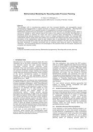
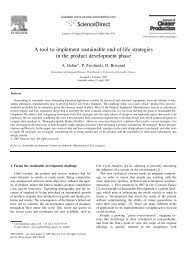
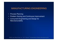
• The resource allocation control monitors the operationcontrol states to update the resource states <strong>for</strong> resourceallocation-purposes (Busy, Idle, or Error).Necessary interactions between the operation control andthe system level controller are as follows:• Communication operations in the operation control generateevents to in<strong>for</strong>m the system level controller of thenecessary operational states: O1C <strong>for</strong> a part loaded intothe cell, O2 C <strong>for</strong> exit buffer request, and OC 3 <strong>for</strong> the partexited from the cell.Finally, interactions between the resource allocation controland the system level controller are as follows:• The resource allocation control can generate a part rejectevent when the part cannot be processed in the cell.When the system level controller receives this rejectevent, the system level controller handles this rejectedpart by either re-routing or scrapping it.• The system level controller generates three events sequentially<strong>for</strong> each part: a part arrival event (S1 C ), theexit buffer availability event (S2 C ), and a part leave event(S3 C).• The process in<strong>for</strong>mation a part arriving in the cell (e.g.,a part flow path) is sent together with the part arrivalevent (S1 C ) by the system level controller.For a normal automatic sequence, these interactions areillustrated by a UML activity diagram in Fig. 1. In thenormal automatic sequence, the events generated by thesystem level controller and the operation control are orderedas follows: S1 C ···O1 C ···O2 C ··· S2 C ···O3 C S3 C .Tracing operationalcontrol statesOperation <strong>Control</strong>Part loadedinto the cellOperationsUnloadingoperationLoadingoperationRequest anexit bufferOperationsO 1CO 2CO 3CPart unloadedout of the cellSystem Level <strong>Control</strong>lerS 3CS 2CS 1CPart ArrivalReject a partDispatchingthe exit bufferExit bufferavailableThe part leave fromthe exit bufferResource Allocation<strong>Control</strong>Accept a partMonitoring states andgenerating operationstart eventsFig. 1. An activity diagram of UML (Unified Modeling Languages) [2]divided by three swimlanes: the operation control, the resource allocationcontrol, and the system level controller. This activity diagram shows a workflow that is comprised of important activities during a normal automaticsequence <strong>for</strong> a part. The communication operations (O1 C, OC 2 , OC 3 ) generateevents to in<strong>for</strong>m the system level controller of the states in the FMC.Theresource allocation control monitors operational states from the operationcontrol and generates operation start events. The system level controllergenerates three events: a part arrival event (S1 C ) with the process in<strong>for</strong>mationof a part, the exit buffer availability event (S2 C), and a part leave event (SC 3 ).The resource allocation control can generate a part reject event to in<strong>for</strong>mthe system level controller that this part cannot be processed in this cellB. Operation BlocksIn addition to interacting with the system level controller,the flexible manufacturing cell controller must interact withequipment controllers and human operators. During manualerror handling, the FMC must keep track of its controlstate. To illustrate such interactions, an activity diagram isprepared <strong>for</strong> a process operation as shown in Fig. 2. Thisdiagram shows the interactions between a process operationdefined in the operation control and a process machineequipment controller. When an operation start event signal isgenerated, the current state is changed from the ‘IDLE’ stateto the ‘RUN’ state. While the corresponding job programis running in the equipment controller, the current state inthe operation control remains in the ‘RUN’ state. If an erroroccurs during this operation, the current state will be changedto the ‘ERROR’ state. In the ‘ERROR’ state, the cause oferror is fixed by the operator through manual manipulation.If the job program is finished without any error, the currentstate will move to the ‘DONE’ state. After a part is taken outof the process machine, this machine is available <strong>for</strong> otheroperations, and the current state is changed from ‘DONE’ to‘IDLE’. In addition, the ‘WAIT’ state (reachable only fromthe ‘ERROR’ state) represents waiting <strong>for</strong> a material handlerto remove the part from the machine by per<strong>for</strong>ming the partscrap operation. Until the part is removed from the machine,this machine cannot be used <strong>for</strong> other operations.In the ‘ERROR’ state, manual error recovery steps aretaken after the cause of error is fixed. In this paper, we restrictthe number of manual error recovery steps to three: Reset,Scrap, and Retry. The operator pushes a button on the HMIto select the appropriate event (‘reset’, ‘scrap’, or ‘retry’) sothat the control state is synchronized with the physical state.The ‘reset’ event moves the control state from ‘ERROR’to ‘IDLE’, indicating that the machine is now ready <strong>for</strong> otheroperations. The ‘scrap’ event requests that the part should bescrapped by a material handler. This event moves the controlstate from ‘ERROR’ to ‘WAIT’, and the control state remainsin ‘WAIT’ until the part is removed from the machine by apart scrap operation. The ‘retry’ event causes the job programto be restarted (although if the true cause of the error has notbeen fixed, it may stop again). In addition, the ‘error’ eventis generated when either the equipment controller or the cellcontroller detects an error.The control states and events in the interaction are influencedby the control mode of the equipment devices. Weassume two control modes: auto mode and manual mode. Inthe auto mode, a normal sequence is executed, while in themanual mode, manual error recovery steps can be taken.Based on the interactions in Fig. 2 and the control mode,the basic process operation block is developed as in Fig. 3and Table I. The process operation block is written in SFC(Sequential Function Chart), one of the IEC61131-3 PLClanguages [5], and has four steps and eight transitions.Table I shows the allowable events and conditions <strong>for</strong> eachcontrol mode. The material handling operation block and thecommunication operation block are defined similarly.8357
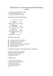
Operation control in FMC controller‘IDLE’‘RUN’ ‘DONE’‘ERROR’‘WAIT’ Equipment controller <strong>for</strong> a process machineProgramrunningProgramProgramfinishedstoppedManual ErrorRecovery or TABLE ITRANSITIONS AND STEPS OF A PROCESS OPERATION BLOCK (SIn:SAFETY INTERLOCK n)Trans. Auto Mode Manual Modet1 operation start ↑t2 operation finish ↑ operation finish ↑t3 part removal ↑∧SI1 part removal ↑∧SI1t4 error ↑∨timer out ↑ error ↑t5retry ↑∧SI2t6reset ↑∧SI1t7scrap ↑∧SI3t8 part removal ↑∧SI1 part removal ↑∧SI1Fig. 2. An activity diagram <strong>for</strong> a process operation divided by twoswimlanes: the operation control in the FMC controller and the equipmentcontroller. This diagram shows the interactions between the operationcontrol in FMC controller and a machine equipment controller duringa process operation. A process operation can have four states: ‘RUN’,‘DONE’, ‘ERROR’, and ‘WAIT’. Three error recovery steps are allowedand their corresponding events (‘reset’, ‘scrap’, and ‘retry’) are generatedby operators. The ‘reset’ event moves the control state from ‘ERROR’to ‘IDLE’. The ‘scrap’ event moves the control state from ‘ERROR’ to‘WAIT’, and the control state remains in ‘WAIT’ until the part is removedfrom the machine by a part scrap operation. The ‘retry’ event causes thejob program to be restarted.Fig. 3.t6t5ERRORWAITt4t7t8IDLERUNDONEt1t2t3A processoperation blockAn ‘IDLE’ step and a process operation block written in SFC.Because there are multiple transitions coming out of someplaces, conflicting transitions can exist in an operation block.When two or more firing conditions of conflicting transitionsare satisfied simultaneously, it is not clear which one shouldbe fired. To avoid such non-deterministic behaviors in theoperation blocks, we define event priorities as follows:Assumption 1 (Event priority): The error event has priorityover the operation finish event in the ‘RUN’ step. Themanual error recovery events are priority ordered as: ‘reset’> ‘retry’ > ‘scrap’. There<strong>for</strong>e, in every control executioncycle, only one transition can be fired even if two or moretransition conditions are satisfied simultaneously.Safety interlock conditions protect parts, resources, and/orhuman operators, but sometimes they are too restrictive andmay generate unnecessary blocking situations [11]. In thispaper, we assume that no safety interlock conditions causeblocking.Assumption 2 (Safety Interlock Conditions): We assumethat the safety interlock conditions protecting parts, resources,and human operators from damage are proper anddo not cause unnecessary blocking situations.When operational states in a basic operation block needSteps Description ActionsIDLE Idle State ‘IDLE’ state onRUN Program Run Send the program number‘RUN’ state onDONE Program Finished ‘DONE’ state onERROR Error State ‘ERROR’ state onWAIT An error recovery operation ‘WAIT’ state onto be further refined, the following restrictions should beimposed to preserve the control properties, as explained insection IV-C.Restriction 1 (Restrictions on the refinement): An operationblock can be refined as long as the following restrictionsare satisfied.1) Every transition should have a single input step and asingle output step (finite state machine).2) When a refined operation block is connected to the‘IDLE’ state, there should exist at least one path fromevery step in the block to the ‘IDLE’ state.Well-developed refined operation blocks can be stored inthe library of control design tools and be reused <strong>for</strong> otherapplications. Using basic or refined blocks and part flowpaths, we can automatically generate the operation control byapplying a simple algorithm to instantiate and group relatedoperation blocks. Finally, by combining the operation controlwith the resource allocation control, we can complete thedevelopment of a cell controller <strong>for</strong> FMC.C. Proof of control behaviorsIn this section, we investigate the behaviors of the cellcontroller developed by the proposed method. In the operationcontrol, the operation blocks were described by SFC(the sequential function chart). However, since SFC is nota <strong>for</strong>mal language, it does not allow direct mathematicalanalysis. For analysis purposes, the operation blocks in SFCneed to be converted into a <strong>for</strong>mal language such as Petrinets [1]. SFC was developed from Petri nets and is verysimilar in terms of its appearance and dynamic evolutionrules. The mathematical properties of Petri nets can be usedto verify and analyze the behaviors of discrete event dynamicsystems, and are used here to verify the behaviors of theproposed FMC controller.For Petri net models of controllers, three important behaviorsare typically considered: liveness, safeness, and reversibility.The physical meaning of these control behaviorscan be phrased as follows [1]:8358
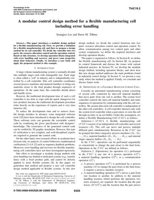
• Liveness means the absence of deadlocks. This guaranteesthat all transitions can eventually be fired.• Safeness guarantees that there is no attempt to requestthe execution of any on-going operation.• Reversibility characterizes the recoverability to the initialstate from any state of the system.The operation control part of the FMC controller is builtfrom operation groups. Each material handler or processmachine resource in the cell has an associated operationgroup that includes the operation blocks <strong>for</strong> all of theoperations that the resource can per<strong>for</strong>m. An initial step(‘IDLE’) has an outgoing transition to the run state of eachoperation block; transitions from the operation blocks backto IDLE are as shown in Fig. 3.To study the behavior of the operation controller, weconvert the SFC operation groups to Petri net models. Althoughthe explicit transition conditions cannot be includedin the Petri net, they will be considered later. The followingproposition shows that each operation group is a stronglyconnected finite state machine as defined in [1].Proposition 4.1: The converted Petri net model of eachoperation group is structurally a strongly connected finitestate machine.Proof: Each operation block converted into a Petri net is afinite state machine since each transition has one input placeand one output place (by definition of finite state machine).In addition, from any place in the converted model, thereexists a transition firing sequence returning to the initial place(‘IDLE’). There<strong>for</strong>e, the converted model <strong>for</strong> each operationgroup is strongly connected. ⋄Since a Petri net model <strong>for</strong> an operation group is a finitestate machine and starts with a single token in the initialstate (‘IDLE’), only one place can hold a token at a timein the group. In addition, each operation group satisfies thefollowing behavioral properties.Proposition 4.2: Each group is live, safe, and reversible ifthe resource allocation control behaves correctly as follows:• Do not attempt the execution of an on-going operation.• Do not allow the preemption of a resource (A resourcein use remains in use.).• Avoid part flow deadlocks in sequences of operations.Proof: Suppose the resource allocation control behaves asmentioned. The safeness of each group of operation blocksis guaranteed by the first two behaviors and Proposition 4.1.Any operation in the sequence can start eventually since theresource allocation control doesn’t cause any part flow deadlockin sequences of operations. Once an operation starts, thisoperation is exclusively controlled by operation blocks in theoperation control. By assumptions 1 and 2, all the eventsin an operation block are asynchronously triggered, andno safety interlock conditions cause unnecessary blockingsituations. From these two assumptions and proposition 4.1,all transitions can be eventually fired, there<strong>for</strong>e each group islive. By proposition 4.1, the liveness property is equivalentto the reversibility property [8]. ⋄Based on these two propositions, the following theoremcan be derived <strong>for</strong> the control behaviors of the FMCFig. 4. The Reconfigurable Factory Testbed at the University of Michiganincludes two flexible manufacturing cells and a conveyor <strong>for</strong> inter-cellmaterial handling [7].controller.Theorem 4.3: The flexible manufacturing cell (FMC)controller is live, safe, and reversible if and only if theresource allocation control behaves as in Proposition 4.2.Proof: (only if) Suppose the flexible manufacturing cellcontroller is live, safe, and reversible. It is clear that anyviolation of the behaviors in Proposition 4.2 leads to thecontradiction of this supposition. (if) Each group of operationblocks is live, safe, and reversible by Proposition 4.2. Sinceeach group is safe, the FMC controller is safe. In auto mode,interactions with other groups can occur only through theresource allocation control. While an operation in a groupis being per<strong>for</strong>med in auto mode, this group is independentof others until the operation is finished. In manual mode,the operation block may interact with other groups onlythrough safety interlock conditions. By assumption 2, there isno blocking situation caused by safety interlock conditions.There<strong>for</strong>e, the FMC controller is live. Also, there’s at leastone transition firing sequence by which each group can returnto its initial place (‘IDLE’) because each group is reversibleand live. There<strong>for</strong>e, the FMC controller is safe, live, andreversible. ⋄V. CASE STUDYTo validate the proposed control design method, a flexiblemanufacturing cell controller was developed <strong>for</strong> one of cellsin the reconfigurable manufacturing test-bed in the Universityof Michigan, see Figure 4. Each cell is comprised of two 3-axis CNC horizontal milling machines and a 6-axis robotwith a gripper. The cell has a PC-based Siemens PLC andis networked over Profibus. The cell controller not onlycommunicates with an in-house system level controller toexchange events and part in<strong>for</strong>mation, but also communicateswith a Web HMI over OPC standard. Since the automaticprogram generation software has not been fully developedyet, some control design steps were manually taken.In an example production scenario, two part flow pathswere specified to produce two different part groups: onepart flow path was B entry O1 M B exit , and the other was8359
B entry O2M B exit . Two part scrap operations were specifiedby O5 H and OH 6 to remove damaged parts from the machinesto a trash can. Both CNC machines (M 1 and M 2 ) couldper<strong>for</strong>m both operations O1 M and O2 M .The resource allocation control was somewhat trivial inthis case because neither the production scenario nor thecell were complex. A newly arrived part was rejected whenboth machines were out of service or when the robot wasout of service. If a part arrived at the entry buffer whileboth machines were working, this newly arrived part wasalso rejected because there was no location holding the parttemporarily. When both CNC machines were idle, the leastrecently-usedmachine was chosen.Three operation groups were created <strong>for</strong> the two CNCmachines and the robot. The group of operation blocks <strong>for</strong>the robot is shown in Fig. 5. This robot could per<strong>for</strong>m sixdifferent operations: two loading operations (O1 H , O3 H ), twounloading operations (O2 H, OH 4 ), and two part scrappingoperations (O5 H , O6 H ). For each operation, a refined operationblock was developed and used. In addition, two communicationoperations (O1C and OC 3 ) were inserted after loading orunloading operations by following the interactions explainedin Section IV-A.ERRORSTATE 1STATE 2STATE 3ERRORERRORSTATE 1STATE 2STATE 3STATE 1STATE 2STATE 3IDLELoading operation to M 1 Loading operation to M 2 Unloading operation to M 1 Unloading operation to M 2STATE 1STATE 2STATE 3STATE 1STATE 2STATE 3ERROR C 3ERROR C ERRORC 1C 1Error recovery operation to M 1ERRORERRORSTATE 1STATE 2STATE 3Error recovery operation <strong>for</strong> M 2Fig. 5. The robot (H 1 ) operation group. This robot can per<strong>for</strong>m sixdifferent operations <strong>for</strong> loading, unloading, and error recovery. The communicationoperation O1 C immediately follows a loading operation (OH 1or O3 H), and the communication operation OC 3 immediately follows anunloading operation (O2 H or OH 4 ). Two part scrapping operations (OH 5 andO6 H ) removed damaged parts from the CNC machines to a trash can.ERRORERRORdoes not have part flow deadlocks, repeated execution ofon-going operations, or preemption. The proposed designmethod was applied to develop the FMC controller of atest cell.As our future work, we will extend this design methodto cover more complex resource allocation control and toinclude the integrated HMI control and RF ID <strong>for</strong> parttracking. In addition, we will develop a design and verificationmethod <strong>for</strong> the safety interlock conditions. Finally,we will propose an automated error recovery frameworkinteracting with human operators.REFERENCES[1] A. A. Desrochers and R. Y. Al-Jaar. Applications of Petri Netsin <strong>Manufacturing</strong> Systems : Modeling, <strong>Control</strong>, and Per<strong>for</strong>manceAnalysis. IEEE Press, 1995.[2] M. Fowler and K. Scott. UML Distrilled. Addison-Wesley, 2000.[3] M. D. Jeng and F. Dicesare. Synthesis using resource control nets <strong>for</strong>modeling shared-resource systems. IEEE Transactions on Roboticsand Automation, 11(3):317–327, 1995.[4] F. L. Lewis, A. Gurel, S. Bogdan, A. Doganalp, and O. Pastravanu.Analysis of deadlock and circular waits using matrix model <strong>for</strong> flexiblemanufacturing systems. Automatica, 34(9):1083–1100, 1998.[5] R. W. Lewis. Programming Industrial <strong>Control</strong> System using IEC1131-3. IEE Publication, 1995.[6] M. R. Lucas and D. M. Tilbury. A study of current logic designpractices in the automotive manufacturing industry. InternationalJournal of Human-Computer Studies, 59(5):725–753, 2003.[7] J. Moyne, J. Korsakas, and D. M. Tilbury. Reconfigurable factorytestbed (RFT): A distributed testbed <strong>for</strong> reconfigurable manufacturingsystems. In Proceedings of the Japan–U.S.A. Symposium on <strong>Flexible</strong>Automation, Denver, CO, July 2004. American Society of MechanicalEngineers (ASME).[8] E. Park, D. M. Tilbury, and P. P. Khargonekar. A modeling and analysismethodology <strong>for</strong> modular logic controller of machining systems usingPetri net <strong>for</strong>malism. IEEE Transactions on Systems, Man, andCybernetics, 31(2):168–188, 2001.[9] J. Park and S. A. Reveliotis. Deadlock avoidance in sequential resourceallocation systems with multiple resource acquisition and flexibleroutings. IEEE Transactions on Automatic <strong>Control</strong>, 46(10):1572–1583,2001.[10] J. Richardsson. A survey of tools and methods <strong>for</strong> design of automatedproduction plants. In Proceedings of the 33rd International Symposiumon Robotics, 2002.[11] J. Richardsson, K. Danielsson, and M. Fabian. <strong>Design</strong> of controlprograms <strong>for</strong> efficient handling of errors in flexible manufacturingcells. In Proceedings of the 2004 IEEE International Conference onRobotics and Automation, pages 2273 – 2278, 2004.[12] M. C. Zhou, F. Dicesare, and A. A. Desrochers. A hybrid methodology<strong>for</strong> synthesis of Petri net models <strong>for</strong> manufacturing systems. IEEETransactions on Robotics and Automation, 8(3):350–361, 1992.The operation groups <strong>for</strong> two CNC machine resourceswere similarly made. Each operation group consists of twoprocess (machining) operation blocks (O1 M and O2 M ), witha communication block (O2 C ) after each process operationblock.VI. CONCLUSION AND FUTURE WORKThe main contribution of this paper was to propose a newmodular control design method <strong>for</strong> a flexible manufacturingcell, and to guarantee the correctness of the control undersome assumptions. In this new design method, modular operationblocks integrated with error handling were developed.We proved that the resulting FMC controller is live, safe,and reversible if and only if the resource allocation control8360