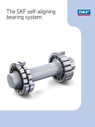
Hydraulic nuts - SKF.com
Hydraulic nuts - SKF.com
Hydraulic nuts - SKF.com

You also want an ePaper? Increase the reach of your titles
YUMPU automatically turns print PDFs into web optimized ePapers that Google loves.
<strong>Hydraulic</strong> <strong>nuts</strong>General InformationSafety re<strong>com</strong>mendationsAs high pressures/forces constitute apotential safety risk, the followinginstructions must be considered:The equipment should only beoperated by trained personnelAlways follow theoperating instructionsCheck the hydraulic nut and allaccessories carefully before use.Never use even slightlydamaged <strong>com</strong>ponentsMake sure all air has beenremoved from the hydraulic system,before putting the equipmentunder pressureDo not use the hydraulic nut forother applications thanmounting/dismounting bearingsAlways use a pressure gaugeAlways prevent the workpiece/tool from being ejected uponsudden release of pressure (e.g. byuse of retaining nut)Do not exceed the maximumpermitted piston displacementUse protective gogglesNever modify the unitUse original parts onlyOnly use clean, re<strong>com</strong>mendedhydraulic oils (e.g. <strong>SKF</strong> LHMF 300,LHDF 900 or similar)In case of any uncertainties asregards the use of the hydraulic nut,contact <strong>SKF</strong>.DescriptionThe hydraulic nut has proved to saveconsiderable effort when mounting ordismounting rolling bearings withtapered bores. It <strong>com</strong>prises two main<strong>com</strong>ponents: a steel ring with agroove in one side face and internalthread (a) and an annular piston whichrests in the groove (b). The seal (c)between the two parts consists of twoO-rings. When oil is pumped into thepressure chamber (d), the piston ispressed out with a force whichnormally is sufficient for mounting anddismounting rolling bearings.The outer ring is provided with anunthreaded hole (g) to hold a dialindicator (h). The measuring tip of theindicator will rest against the shoulderof the piston indicating the axial travelof the same.NoteThe drive-up distance can be usedto determine correct mounting;click here for more info.To connect the oil hose, there are twothreaded holes, one in the side face ofthe steel ring (e) and the other in itscylindrical outside surface (f). Thehole which is not in use is pluggedwith a ball plug, that is supplied withthe nut.All hydraulic <strong>nuts</strong> are equipped withnipple 729832 A for quick connectionto the oil supply.A spare set of O-rings, a maintenanceset and a tommy section bar fortightening the nut are all includedas standard.Load carrying ability<strong>SKF</strong> hydraulic <strong>nuts</strong> are designed towithstand the pressure normallyencountered when rolling bearingsare mounted or dismounted.The maximum pressure in absoluteterms depends on the pistondisplacement, the actual nut size andwhether back-up rings are used ornot. The smaller the nut and theshorterthe piston displacement, the higherpressure the nut can take.A back-up ring will also increase theload carrying ability, especially forbigger <strong>nuts</strong>.Unthreaded executionAll HMV-<strong>nuts</strong> are also available in anunthreaded execution with anadditionto the designation of /A101. All majordimensions are exactly the same asfor the corresponding HMV-nut.For bore diameters please click here.Heavy duty series of hydraulicringsA special heavy duty series ofhydraulic rings, mainly for fittingmarine <strong>com</strong>ponents, are alsoavailable from <strong>SKF</strong>. They are normallyunthreadedand can take pressure up to70 MPa (10,000 psi). Click here fordetailed information.How to apply the nutTo enable easy mounting especiallyfor larger <strong>nuts</strong>, it is important that thenut is properly centred on the matingthread before screwed on. For bigger<strong>nuts</strong> a proper support has to becreated under the nut. When thebearing is mounted on a sleeve, makesure that the sleeve is straight, i.e. thethread is aligned over the slotted partof the sleeve. It is re<strong>com</strong>mended toalways use a thread lubricant beforeapplying the nut on the mating thread.When the nut is to be applied, atommy bar is provided with the nut tobe used as a handle. This is insertedin one of the four unthreaded holes inthe outside cylindrical surface, or inone of the two holes on the sidesurface.How to generate the pressureThe requisite pressure can best beproduced using a pump which willgive at least 100 MPa (14,500 psi).Suitable pumps from the <strong>SKF</strong> rangeare 729124 for <strong>nuts</strong> up to andincluding size 54, and TMJL 100,TMJA 70E, 728619 or TMJL 50 forlarger sizes.Oil having a viscosity of approx.300 mm²/s at the operatingtemperature, e.g. <strong>SKF</strong> mounting fluidLHMF 300, should be used aspressure medium. Less viscous oilsshould be used, for mounting in thecold. When connecting the pump be
sure that all air is removed from thehydraulic system. This can be done byopening one of the plugs and byinjecting oil simultaneously untilleakage occurs.a. internally threaded steel ringb. annular pistonc. O-ringsd. pressure chambere. connection hole in side facef. connection hole in outside surfaceg. unthreaded hole for dial indicatorh. dial indicatorMounting of bearingsThe nut should be carefully screwedon to a threaded section of the shaftor the sleeve until it abuts the bearinginner ring (fig. 1, 2), the withdrawalsleeve(fig. 3) or a special support nut/plate(fig. 4). It is important that as much aspossible, but not less than 80% of thethread of the hydraulic nut isengaged.If this is not possible, a help ring tosupport underneath the nut isnecessary. The piston should then befully retracted into the ring. A pump isused to inject pressurised oil into thenut. The permissible stroke (axialdisplacement) has been chosen toenable all bearings having bores witha taper of 1:12 or 1:30 to be mountedin a single operation. The permittedpiston displacement, which isindicated by a groove in the outside ofthe piston, should however never beexceeded.After mounting has been <strong>com</strong>pleted,the return valve of the pump should beopened so that the pressurised oil canleave the nut. To <strong>com</strong>pletely emptythe nut, the piston has to be returnedto its original position. This is mosteasily ac<strong>com</strong>plished by screwing thenut further up the shaft or sleevethread.For correct interference fit and/orinternal clearance in the bearingplease click here (or see publicationMP502; included with the HMV nut) orpublication 4555 E (for CARB ® ).Mounting1. HMV E nut for driving the bearingonto a tapered seating.3. HMV E nut screwed onto the shaftfor driving in a withdrawal sleeve.2. HMV E nut for driving the bearingonto an adapter sleeve.4. HMV E nut and special stop nut fordriving in a withdrawal sleeve.Dismounting of bearingsDismounting
When dismounting rolling bearingsfrom withdrawal or adapter sleeves,the hydraulic nut is screwed on to thesleeve thread until it rests against thebearing inner ring (fig. 5), or against aspecial support ring (fig. 6).By displacing the piston, the sleevewill be withdrawn from the bearingbore, or the bearing will be pressed offthe adapter sleeve.5. HMV E nut used to free awithdrawal sleeve.6. HMV E nut and stop ring in position topress an adapter sleeve free.MaintenanceWhen the nut is not in use, it shouldbe protected against rust and any oilsupply leads should be plugged toprevent entry of dirt.DimensionsIn the tables on following pagesdimensions are given for <strong>SKF</strong>standard hydraulic <strong>nuts</strong> HMV ...(metric), and HMVC... (inch) as wellas for hydraulic <strong>nuts</strong> withoutthreads.The <strong>nuts</strong> may also be made toother sizes, with special threads orunthreaded bores. Further informationwill be provided on request.In case of leakageIf oil leaves the hydraulic nut when thepiston is operated, this generallymeans the seal is torn or damagedand must be replaced. To do this, thepiston has to be pressed out of thering. To facilitate this operation, threeauxiliary holes with closure nipples areprovided in the full face of the ring.Using threaded pins, which aresupplied with the nut, the piston canbe pushed out of the ring. The O-ringsare then removed, the groovescleaned and the new O-rings put inposition. If necessary, grease can beused to keep the new O-rings in thecorrect position during thereplacement operation. A reserve setof O-rings are also supplied with thenut. Additional replacement rings ifneeded can be obtained from <strong>SKF</strong>.Replacement partsDescriptionDesignationO-rings Nut designation followed by /233983, e.g. HMV 10/233983Ball plug233950 EQuick connection nipple729832 AMaintenance set HMVM 10/29 (nut size 10 to 29)(threaded pins, copper rings, hexagonal keys) HMVM 30/69 (nut size 30 to 69)HMVM 70/200 (nut size 70 to 200)AccessoriesThe following pumps are re<strong>com</strong>mended for the various nut sizesHMV(C) 10E - HMV(C) 54E729124 / TMJL 50 / TMJL 100 / 728619 E / TMJA 70EHMV(C) 56E - HMV(C) 92ETMJL 50 / TMJL 100 / 728619 E / TMJA 70EHMV(C) 94E - HMV(C) 200ETMJL 50 / 728619 EMounting fluid LHMF 300/5Dial indicatorsTMCD 5P (parallel dial, 0-5 mm)TMCD 1/2R (right angle dial 0-0.5 in)TMCD 10R (right angle dial, 0-10 mm)Precision gaugeTMJG 100D (100 MPa / 15000 psi, G 1/4 connection)© <strong>SKF</strong> Maintenance Products Date of issue: 2003-06-11