AC200 Series Installation and Operation Manual - TEMCo Industrial ...
AC200 Series Installation and Operation Manual - TEMCo Industrial ...
AC200 Series Installation and Operation Manual - TEMCo Industrial ...

You also want an ePaper? Increase the reach of your titles
YUMPU automatically turns print PDFs into web optimized ePapers that Google loves.
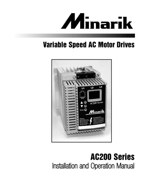
Variable Speed AC Motor Drives<strong>AC200</strong> <strong>Series</strong><strong>Installation</strong> <strong>and</strong> <strong>Operation</strong> <strong>Manual</strong>
THE <strong>AC200</strong> SUB-MICRO DRIVEINPUT POWERTERMINALSGROUNDLUGELECTRONICPROGRAMMINGMODULE (EPM)3-DIGIT LEDDISPLAYPROGRAMMINGBUTTONSCUSTOMERTERMINALSTRIPOUTPUT (MOTOR) TERMINALS2
1.0 GENERAL1.1 PRODUCTS COVERED IN THIS MANUALThis manual covers the Minarik <strong>AC200</strong> <strong>Series</strong> Variable Frequency Drive.1.2 PRODUCT CHANGESMinarik Drives reserves the right to discontinue or make modifications to thedesign of its products without prior notice, <strong>and</strong> holds no obligation to makemodifications to products sold previously. Minarik Drives also holds no liabilityfor losses of any kind which may result from this action. Instruction manualswith the most up-to-date information are available for download from the MinarikDrives website (www.minarikdrives.com).1.3 UNCONDITIONAL WARRANTYMinarik Drives (referred to as “the Corporation”) warrants that its manufacturedproducts will be free from defects in workmanship <strong>and</strong> material for twelve (12)months or 3,000 hours, whichever comes first, from date of manufacturethereof. Within this warranty period, the Corporation will repair or replace suchproducts that are returned to Minarik Drives, 14300 De La Tour Drive, SouthBeloit, IL, 61080, USA.This warranty shall not apply to any product that has been repaired byunauthorized persons. The Corporation is not responsible for removal,installation, or any other incidental expenses incurred in shipping the product to<strong>and</strong> from the repair point.This warranty is in lieu of all other warranties, expressed or implied. No otherperson, firm or corporation is authorized to assume, for Minarik Drives, anyother liability in connection with the demonstration or sale of its products.1.4 RECEIVINGInspect all cartons for damage which may have occurred during shipping.Carefully unpack equipment <strong>and</strong> inspect thoroughly for damage or shortage.Report any damage to carrier <strong>and</strong>/or shortages to supplier. All majorcomponents <strong>and</strong> connections should be examined for damage <strong>and</strong> tightness,with special attention given to PC boards, plugs, knobs <strong>and</strong> switches.1.5 CUSTOMER MODIFICATIONMinarik Drives, its sales representatives <strong>and</strong> distributors, welcome theopportunity to assist our customers in applying our products. Many customizingoptions are available to aid in this function. Minarik Drives cannot assume3
1Mode2EPM561112214152513A13B13C230312.0 <strong>AC200</strong> DIMENSIONSWL1L2L30.38"TXBH<strong>AC200</strong> SERIESRTXAT1 T2 T3 B- B+0.38"0.18"0.66"DP 0.19"DIA. SLOTHP kW INPUT MODEL H W D P RVOLTAGE0.25 0.18 208/240 AC212B-0.2 5.75 (146) 2.88 (73) 3.94 (100) 0.80 (20) 4.37 (111)0.5 0.37 208/240 AC212B-0.4 5.75 (146) 2.88 (73) 3.94 (100) 0.80 (20) 4.37 (111)400/480 AC214T-0.4 5.75 (146) 2.88 (73) 3.94 (100) 0.80 (20) 4.37 (111)1 0.75 208/240 AC212B-0.75 5.75 (146) 2.88 (73) 4.74 (120) 1.60 (41) 4.37 (111)208/240 AC212T-0.75 5.75 (146) 2.88 (73) 4.74 (120) 1.60 (41) 4.37 (111)400/480 AC214T-0.75 5.75 (146) 2.88 (73) 4.74 (120) 1.60 (41) 4.37 (111)480/590 AC215T-0.75 5.75 (146) 2.88 (73) 4.74 (120) 1.60 (41) 4.37 (111)1.5 1.1 208/240 AC212B-1.1 5.75 (146) 3.76 (96) 5.24 (133) 1.90 (48) 4.37 (111)208/240 AC212T-1.1 5.75 (146) 2.88 (73) 5.74 (146) 2.60 (66) 4.37(111)400/480 AC214T-1.1 5.75 (146) 2.88 (73) 5.74 (146) 2.60 (66) 4.37(111)4
<strong>AC200</strong> DIMENSIONS (cont.)HP kW INPUT MODEL H W D P RVOLTAGE2 1.5 208/240 AC212B-1.5 5.75 (146) 3.76 (96) 6.74 (171) 3.40 (86) 4.37 (111)208/240 AC212T-1.5 5.75 (146) 2.88 (73) 5.74 (146) 2.60 (66) 4.37 (111)480/480 AC214T-1.5 5.75 (146) 2.88 (73) 5.74 (146) 2.60 (66) 4.37 (111)480/590 AC215T-1.5 5.75 (146) 2.88 (73) 5.74 (146) 2.60 (66) 4.37 (111)3 2.2 208/240 AC212B-2.2 5.75 (146) 3.76 (96) 6.74 (171) 3.40 (86) 3.25 (83)208/240 AC212T-2.2 5.75 (146) 3.76 (96) 5.74 (146) 2.60 (66) 3.06 (78)400/480 AC214T-2.2 5.75 (146) 3.76 (96) 5.74 (146) 2.60 (66) 3.06 (78)480/590 AC215T-2.2 5.75 (146) 3.76 (96) 6.74 (171) 3.40 (86) 4.37 (111)5 3.7 208/240 AC212B-3.7 7.75 (197) 5.02 (128) 7.18 (182) 3.40 (86) 4.81 (122)208/240 AC212T-3.7 5.75 (146) 3.76 (96) 6.74 (171) 3.40 (86) 3.25 (83)400/480 AC214T-3.7 5.75 (146) 3.76 (96) 6.74 (171) 3.40 (86) 3.25 (83)480/590 AC215T-3.7 5.75 (146) 3.76 (96) 6.74 (171) 3.40 (86) 3.25 (83)7.5 5.5 208/240 AC212T-5.5 7.75 (197) 5.02 (128) 7.18 (192) 3.40 (86) 4.81 (122)400/480 AC214T-5.5 7.75 (197) 5.02 (128) 7.18 (192) 3.40 (86) 4.81 (122)480/590 AC215T-5.5 7.75 (197) 5.02 (128) 7.18 (192) 3.40 (86) 4.81 (122)10 7.5 208/240 AC212T-7.5 7.75 (197) 5.02 (128) 7.18 (192) 3.40 (86) 4.81 (122)400/480 AC214T-7.5 7.75 (197) 5.02 (128) 7.18 (192) 3.40 (86) 4.81 (122)480/590 AC215T-7.5 7.75 (197) 5.02 (128) 7.18 (192) 3.40 (86) 4.81 (122)15 11 208/240 AC212T-11 9.75 (248) 6.68 (170) 8.00 (203) 3.60 (91) 6.30 (160)400/480 AC214T-11 9.75 (248) 6.68 (170) 8.00 (203) 3.60 (91) 6.30 (160)480/590 AC215T-11 9.75 (248) 6.68 (170) 8.00 (203) 3.60 (91) 6.30 (160)20 15 208/240 AC212T-15 9.75 (248) 6.68 (170) 8.00 (203) 3.60 (91) 6.30 (160)400/480 AC214T-15 9.75 (248) 6.68 (170) 8.00 (203) 3.60 (91) 6.30 (160)480/590 AC215T-15 9.75 (248) 6.68 (170) 8.00 (203) 3.60 (91) 6.30 (160)25 18.5 400/480 AC214T-18.5 9.75 (248) 6.68 (170) 8.00 (203) 3.60 (91) 6.30 (160)480/590 AC215T-18.5 9.75 (248) 6.68 (170) 8.00 (203) 3.60 (91) 6.30 (160)5
1Mode2EPM56111221415252613A13B13C30312.1 <strong>AC200</strong> THROUGH-HOLE MOUNT DIMENSIONSWL1L2L3H<strong>AC200</strong> SERIESDTXATXBPT1 T2 T3 B- B+HP kW INPUT MODEL H W D PVOLTAGE1 0.75 208/240 AC212B-0.75F 7.72 (196) 6.80 (173) 4.55 (116) 1.20 (30)208/240 AC212T-0.75F 7.72 (196) 6.80 (173) 4.55 (116) 1.20 (30)400/480 AC214T-0.75F 7.72 (196) 6.80 (173) 4.55 (116) 1.20 (30)480/590 AC215T-0.75F 7.72 (196) 6.80 (173) 4.55 (116) 1.20 (30)1.5 1.1 208/240 AC212B-1.1F 7.72 (196) 6.80 (173) 4.75 (121) 1.20 (30)208/240 AC212T-1.1F 7.72 (196) 6.80 (173) 4.55 (116) 1.20 (30)400/480 AC214T-1.1F 7.72 (196) 6.80 (173) 4.55 (116) 1.20 (30)2 1.5 208/240 AC212B-1.5F 7.72 (196) 6.80 (173) 4.75 (121) 1.20 (30)208/240 AC212T-1.5F 7.72 (196) 6.80 (173) 4.55 (116) 1.20 (30)400/480 AC214T-1.5F 7.72 (196) 6.80 (173) 4.55 (116) 1.20 (30)480/590 AC215T-1.5F 7.72 (196) 6.80 (173) 4.55 (116) 1.20 (30)3 2.2 208/240 AC212B-2.2F 7.72 (196) 8.54 (217) 5.30 (135) 1.75 (44)208/240 AC212T-2.2F 7.72 (196) 8.54 (217) 5.10 (130) 1.75 (44)400/480 AC214T-2.2F 7.72 (196) 8.54 (217) 5.10 (130) 1.75 (44)480/590 AC215T-2.2F 7.72 (196) 8.54 (217) 5.30 (135) 1.75 (44)
<strong>AC200</strong> THROUGH-HOLE MOUNT DIMENSIONS (cont.)HP kW INPUT MODEL H W D PVOLTAGE5 3.7 208/240 AC212B-3.7F 9.59 (244) 11.14 (283) 7.65 (194) 3.60 (91)208/240 AC212T-3.7F 7.72 (196) 8.54 (217) 6.30 (160) 2.75 (70)400/480 AC214T-3.7F 7.72 (196) 8.54 (217) 6.30 (160) 2.75 (70)480/590 AC215T-3.7F 7.72 (196) 8.54 (217) 6.30 (160) 2.75 (70)7.5 5.5 208/240 AC212T-5.5F 11.59 (294) 11.14 (283) 7.65 (194) 3.60 (91)400/480 AC214T-5.5F 9.59 (244) 11.14 (283) 7.65 (194) 3.60 (91)480/590 AC215T-5.5F 9.59 (244) 11.14 (283) 7.65 (194) 3.60 (91)10 7.5 208/240 AC212T-7.5F 15.59 (396) 11.14 (283) 7.65 (194) 3.60 (91)400/480 AC214T-7.5F 11.59 (294) 11.14 (283) 7.65 (194) 3.60 (91)480/590 AC215T-7.5F 11.59 (294) 11.14 (283) 7.65 (194) 3.60 (91)15 11 208 / 240 AC212T-11F 18.09 (459) 11.14 (283) 8.29 (211) 3.60 (91)400 / 480 AC214T-11F 15.59 (396) 11.14 (283) 8.29 (211) 3.60 (91)480 / 590 AC215T-11F 15.59 (396) 11.14 (283) 8.29 (211) 3.60 (91)20 15 400 / 480 AC214T-15T 18.09 (459) 11.14 (283) 8.29 (211) 3.60 (91)480 / 590 AC215T-15F 18.09 (459) 11.14 (283) 8.29 (211) 3.60 (91)25 18.5 400 / 480 AC214T-18.5F 28.50 (724) 10.34 (263) 8.39 (213) 3.70 (94)480 / 590 AC215T-18.5F 28.50 (724) 10.34 (263) 8.39 (213) 3.70 (94)Note: Refer to Appendix A for mounting template dimensions for thethrough-hole mount option.7
3.0 <strong>AC200</strong> MODEL DESIGNATION CODEThe <strong>AC200</strong> model number gives a full description of the basic drive unit (see examplebelow).EXAMPLE: AC212B-0.75F (<strong>AC200</strong> <strong>Series</strong>, 208/240 Vac, 1 HP, single or three phaseinput, with through hole mounting for special heat sink)<strong>Series</strong>AC2 = <strong>AC200</strong> <strong>Series</strong> Variable Speed AC Motor DriveEnclosure Type1 = IP20Input Voltage2 = 208/240 VAC (for 208, 220, 230 <strong>and</strong> 240 VAC; 50 or 60 Hz)4 = 400/480 VAC (for 380, 415, 440, 460 <strong>and</strong> 480 VAC; 50 or 60 Hz)5 = 480/590 VAC (for 460, 480, 550, 575 <strong>and</strong> 600 VAC; 50 or 60 Hz)Input PhaseT = Three-phase input onlyB = Single- or three-phase inputHorsepower0.2 = 1/4HP 1.1 = 1 1/2 HP 3.7 = 5 HP 11 = 15 HP0.4 = 1/2 HP 1.5 = 2 HP 5.5 = 7 1/2 HP 15 = 20 HP0.75 = 1 HP 2.2 = 3 HP 7.5 = 10 HP 18.5 = 25 HPOptionsF = Through hole mounting with special heat sinkV = High frequency output – up to 1000 Hz8
4.0 <strong>AC200</strong> SPECIFICATIONSStorage Temperature-20º to +70º CAmbient Operating Temperature 0º to 50º C (derate 2.5% per ºC above 50º)Ambient HumidityMaximum AltitudeInput Line Voltages< 95% (non-condensing)3300 ft (1000m) above sea level (derate 5% per additional 3300 ft)208/240 VAC, 400/480 VAC, 480/590 VACInput Voltage Tolerance + 10%, -15%Input Frequency ToleranceOutput Wave FormOutput FrequencyCarrier FrequencyService Factor48 to 62 HzSine Coded PWM0 - 240 Hz (consult factory for higher output frequencies)4 kHz to 10 kHz1.00 (up to 6 kHz carrier, derate above 6 kHz)Efficiency Up to 98%Power Factor (displacement)Overload Current CapacitySpeed Reference FollowerControl VoltagePower Supply for Auxiliary RelaysAnalog OutputsDigital Outputs0.96 or better150% for 60 seconds, 180% for 30 seconds0-10 VDC, 4-20 mA15 VDC50 mA at 12 VDC0 - 10 VDC or 2 - 10 VDC: Proportional to frequency or loadOpen-collector outputs: 50 mA at 30 VDC9
5.0 <strong>AC200</strong> RATINGSMODEL # FOR MOTORS RATED INPUT (50 - 60 Hz) OUTPUT CURRENT HEAT LOSS(note 1) HP kW INPUT CURRENT POWER (AMPS) (WATTS)PHASE (AMPS) (kVA) (note 6)AC212B SERIES (SEE NOTE 3) 208 / 240 VAC 0-200/230 VAC STD THRUAC212B-0.2 0.25 0.20 1 3.6 / 3.2 0.76 1.6 / 1.4 19 N/AAC212B-0.2 0.25 0.20 3 1.9 / 1.7 0.71 1.6 / 1.4 19 N/AAC212B-0.4 0.5 0.37 1 5.4 / 4.7 1.2 2.5 / 2.2 26 N/AAC212B-0.4 0.5 0.37 3 3.1 / 2.7 1.1 2.5 / 2.2 26 N/AAC212B-0.75 1 0.75 1 10.6 / 9.2 2.2 4.8 / 4.2 49 18AC212B-0.75 1 0.75 3 5.8 / 5.1 2.1 4.8 / 4.2 49 18AC212B-1.1 1.5 1.1 1 13.9 /12.0 2.9 6.9 / 6.0 82 23AC212B-1.1 1.5 1.1 3 8.0 / 6.9 2.9 6.9 / 6.0 82 23AC212B-1.5 2 1.5 1 14.8 / 12.9 3.1 7.8 / 6.8 86 26AC212B-1.5 2 1.5 3 9.1 / 7.9 3.2 7.8 / 6.8 86 26AC212B-2.2 3 2.2 1 19.7 /17.1 4.1 11.0 / 9.6 130 29AC212B-2.2 3 2.2 3 12.4 / 10.8 4.4 11.0 / 9.6 130 29AC212B-3.7 5 3.7 1 29 / 26 6.1 17.5 /15.2 212 40AC212B-3.7 5 3.7 3 19.6 / 17.1 7.1 17.5 / 15.2 212 40AC212T SERIES (SEE NOTE 3) 208 / 240 VAC 0-200/230 VAC STD THRUAC212T-0.75 1 0.75 3 5.8 / 5.1 2.1 4.8 / 4.2 41 11AC212T-1.1 1.5 1.1 3 8.0 / 6.9 2.9 6.9 / 6.0 69 13AC212T-1.5 2 1.5 3 9.1 /7.9 3.3 7.8 / 6.8 78 15AC212T-2.2 3 2.2 3 12.4 / 10.8 4.5 11.0 / 9.6 117 20AC212T-3.7 5 3.7 3 19.6 / 17.1 7.1 17.5 /15.2 187 22AC212T-5.5 7.5 5.5 3 28 / 25 10.3 25 / 22 286 31AC212T-7.5 10 7.5 3 34 / 32 13.1 30 / 28 379 39AC212T-11 15 11 3 54 / 48 20.0 48 / 42 476 51AC212T-15 20 15 3 65 / 61 25.4 58 / 54 648 N/AAC214T SERIES (SEE NOTE 4) 400 / 480 VAC 0-400/460 VAC STD THRUAC214T-0.4 0.5 0.37 3 1.6 / 1.4 1.1 1.3 / 1.1 26 N/AAC214T-0.75 1 0.75 3 2.9 / 2.5 2.1 2.4 / 2.1 38 12AC214T-1.1 1.5 1.1 3 4.0 / 3.6 3.0 3.4 / 3.0 56 13AC214T-1.5 2 1.5 3 4.6 / 4.0 3.3 3.9 / 3.4 67 14AC214T-2.2 3 2.2 3 6.2 / 5.4 4.5 5.5 / 4.8 100 19AC214T-3.7 5 3.7 3 9.8 / 8.6 7.1 8.7 / 7.6 168 22AC214T-5.5 7.5 5.5 3 14.2 / 12.4 10.3 12.6 / 11.0 254 29AC214T-7.5 10 7.5 3 18.1 / 15.8 13.1 16.1 / 14.0 310 37AC214T-11 15 11 3 27 / 24 20.0 24 / 21 390 42AC214T-15 20 15 3 35 / 31 25.8 31 / 27 530 57AC214T-18.5 25 18.5 3 44 / 38 31.6 39 / 34 648 7210
MODEL # FOR MOTORS RATED INPUT (50 - 60 Hz) OUTPUT CURRENT HEAT LOSS(note 1) HP kW INPUT CURRENT POWER (AMPS) (WATTS)PHASE (AMPS) (kVA) (note 6)AC215T SERIES (SEE NOTE 5) 480 / 590 VAC 0 - 460 / 575 VAC STD THRUAC215T-0.75 1 0.75 3 2.2/ 2.0 1.9 / 2.0 1.9 / 1.7 40 12AC215T-1.5 2 1.5 3 4.0 / 3.5 3.3 / 3.6 3.4 / 3.0 67 13AC215T-2.2 3 2.2 3 4.7 / 4.7 3.9 / 4.8 4.2 / 4.2 100 14AC215T-3.7 5 3.7 3 7.4 / 7.4 6.1 / 7.5 6.6 / 6.6 168 19AC215T-5.5 7.5 5.5 3 11.2 / 11.2 9.3 / 11.4 9.9 / 9.9 254 29AC215T-7.5 10 7.5 3 13.7 / 13.7 11.4 / 14.0 12.2 / 12.2 310 37AC215T-11 15 11 3 22 / 22 18.3 / 22.5 19.0 / 19.0 390 42AC215T-15 20 15 3 27 / 27 22.4 / 27.6 24 / 24 530 57AC215T-18.5 25 18.5 3 31 /31 25.8 / 31.7 27 / 27 648 72NOTES:NOTE 1: See Section 3.0 for model number breakdown.NOTE 3: The higher current ratings are for 208 VAC input; the lower current ratings are for 240 VAC input.NOTE 4: The higher current ratings are for 400 VAC input; the lower current ratings are for 480 VAC input.NOTE 5: The higher current ratings are for 480 VAC input; the lower current ratings are for 590 VAC input.NOTE 6: STD = st<strong>and</strong>ard unit; THRU = through-hole mount unit. Values are worst-case(not typical) for 6 kHz carrier frequency at full speed <strong>and</strong> full load.6.0 INSTALLATIONWarning<strong>AC200</strong> drives are intended for inclusion within other equipment, by professional electricalinstallers. They are not intended for st<strong>and</strong>-alone operation.Drives must not be installed where subject to adverse environmental conditions, such ascombustible, oily, or hazardous vapors or dust; excessive moisture or dirt; vibration; orexcessive ambient temperature. Consult Minarik for more information on the suitability ofa drive to a particular environment.<strong>AC200</strong> models are suitable for UL pollution degree 2 environment only, <strong>and</strong> MUST beinstalled in an electrical enclosure which will provide complete mechanical protection<strong>and</strong> will maintain the internal temperature within the drive’s ambient operatingtemperature rating. All drive models MUST be mounted in a vertical position forproper heatsink cooling.11
Maintain a minimum spacing around the drive of at least one inch (25 mm) on eachside <strong>and</strong> two inches (50 mm) on the top <strong>and</strong> bottom for units rated up to 5 HP (3.7kW). For units rated 7.5 - 25 HP (5.5 - 18.5 kW), maintain at least 2 inches (50 mm)on each side <strong>and</strong> 4 inches (100 mm) on the top <strong>and</strong> bottom. Allow more spacing ifthe drive is mounted next to other heat-producing equipment. Do not mount drivesabove other drives or heat producing equipment. Fans or blowers should be used toinsure proper cooling in tigh quarters.In order to properly size an enclosure, the heat generated by the drive(s) must beknown. Refer to the HEAT LOSS columns in Section 5.0 <strong>AC200</strong> Ratings. The STDcolumn is for st<strong>and</strong>ard units, <strong>and</strong> the THRU column is for through-hole mount units(drives with the through-hole mount option still generate some heat inside theenclosure that must be taken into account). An enclosure manufacturer can thendetermine the required enclosure size based on the total heat generated inside theenclosure (from the drive(s) <strong>and</strong> other heat sources), the maximum allowabletemperature inside the enclosure, the maximum ambient temperature outside theenclosure, <strong>and</strong> the enclosure properties.The <strong>AC200</strong> <strong>Series</strong> is UL approved for solid state motor overload protection.Therefore, a separate thermal overload relay is not required for single motorapplications.6.1 INSTALLATION AFTER A LONG PERIOD OF STORAGEWarningSevere damage to the drive can result if it is operated after a long period of storage orinactivity without reforming the DC bus capacitors!If input power has not been applied to the drive for a period of time exceeding threeyears (due to storage, etc), the electrolytic DC bus capacitors within the drive canchange internally, resulting in excessive leakage current. This can result in prematurefailure of the capacitors if the drive is operated after such a long period of inactivity orstorage.In order to reform the capacitors <strong>and</strong> prepare the drive for operation after a longperiod of inactivity, apply input power to the drive for 8 hours prior to actuallyoperating the motor.12
6.2 EXPLOSION PROOF APPLICATIONSExplosion proof motors that are not rated for inverter use lose their certification whenused for variable speed. Due to the many areas of liability that may be encounteredwhen dealing with these applications, the following statement of policy applies:“Minarik Drives inverter products are sold with no warranty of fitness for a particularpurpose or warranty of suitability for use with explosion proof motors. Minarik Drivesaccepts no responsibility for any direct, incidental or consequential loss, cost, ordamage that may arise through the use of its AC inverter products in theseapplications. The purchaser expressly agrees to assume all risk of any loss, cost, ordamage that may arise from such application. Minarik Drives or Minarik Drives’sengineering department will not knowingly approve applications involving explosionproof motors.”7.0 INPUT AC POWER REQUIREMENTSWarningHazard of electrical shock! Capacitors retain charge after power is removed. Disconnectincoming power <strong>and</strong> wait until the voltage between termianls B+ <strong>and</strong> B- is 0 VDC beforeservicing the drive.The input voltage must match the nameplate voltage rating of the drive. Voltagefluctuation must not vary by greater than 10% overvoltage or 15% undervoltage.NOTE: Drives with dual input voltage ratings must be programmed for the propersupply voltage (refer to Parameter 01 - LINE VOLTAGE SELECTION in Section 15.0 -DESCRIPTION OF PARAMETERS).The drive is suitable for use on a circuit capable of delivering not more than 5,000RMS symmetrical amperes at 5 HP (3.7 kW) <strong>and</strong> below, <strong>and</strong> 18,000 RMSsymmetrical amperes at 7.5 (5.5 kW) <strong>and</strong> above, at the drives rated voltage.If the kVA rating of the AC supply transformer is greater than 10 times the input kVArating of the drive(s), an isolation transformer or 2-3% input line reactor must beadded to the line side of the drive(s).Three phase voltage imbalance must be less than 2.0% phase to phase. Excessivephase to phase imbalance can cause severe damage to the drive’s power components.13
Motor voltage should match line voltage in normal applications. The drive’s maximumoutput voltage will equal the input voltage. Use extremem caution when using amotor with a voltage rating which is different from the input line voltage.7.1 INPUT VOLTAGE RATINGSAC212T <strong>Series</strong> drives are rated for 208/240 Vac, three phase, 50-60 Hz input. The drivewill function with input voltages of 208 to 240 Vac (+ 10%, - 15%), at 48 to 62 Hz.AC212B <strong>Series</strong> drives are rated for 208/240 Vac, single or three phase, 50-60 Hz input.The drive will function with input voltage of 208 to 240 Vac (+10%, -15%), at 48 to 62 Hz.AC214T <strong>Series</strong> drives are rated for 400/480 Vac three phase, 50-60 Hz input. The drivewill function with input voltages of 400 to 480 Vac (+ 10%, - 15%), at 48 to 62 Hz.AC215T <strong>Series</strong> drives are rated for 480/590 Vac, three phase, 50-60 Hz input, <strong>and</strong> willfunction with input voltages of 480 to 590 Vac (+ 10%, - 15%), at 48 to 62 Hz.NOTE: Parameter 01 (LINE VOLTAGE SELECTION) must be programmed accordingto the applied input voltage. See Section 15.0 - DESCRIPTION OF PARAMETERS.7.2 INPUT FUSING AND DISCONNECT REQUIREMENTSA circuit breaker or a disconnect switch with fuses must be provided in accordancewith the National Electric Code (NEC) <strong>and</strong> all local codes.14
NOTE 1: Applicable national <strong>and</strong> local electrical codes take precedence overrecommendations in the following tables.INPUT FUSE & CIRCUIT BREAKER RATINGS208/240 Vac, 1 phase 208/240 Vac, 3 phase 400/480 Vac, 3 phase 480/590 Vac 3 phaseMODEL RATING MODEL RATING MODEL RATING MODEL RATINGAC212B-0.2 10A AC212B-0.2 10AAC212B-0.4 10A AC212B-0.4 10A AC214T-0.4 10AAC212B-0.75 15A AC212*-0.75 10A AC214T-0.75 10A AC215T-0.75 10AAC212B-1.1 20A AC212*-1.1 12 / 10A AC214T-1.1 10AAC212B-1.5 25 / 20A AC212*-1.5 15 / 12A AC214T-1.5 10A AC215T-1.5 10AAC212B-2.2 30 / 25A AC212*-2.2 20 / 15A AC214T-2.2 10A AC215T-2.2 10AAC212B-3.7 45 / 40A AC212*-3.7 30 / 25A AC214T-3.7 15A AC215T-3.7 12AAC212T-5.5 45 / 40A AC214T-5.5 20A AC215T-5.5 20AAC212T-7.5 50 / 50A AC214T-7.5 30 / 25A AC215T-7.5 20AAC212T-11 80 / 75A AC214T-11 40 / 35A AC215T-11 30AAC212T-15 100 / 90A AC214T-15 50 / 45A AC215T-15 40AAC214T-18.5 70 / 60A AC215T-18.5 45ANOTE 2: Use UL Class CC or Class T fast-acting, current limiting type fuses. Selectfuses with low I 2 T values, rated at 200,000 AIC. Recommended fuses are BussmanKTK-R, JJN, <strong>and</strong> JJS. Similar fuses with equivalent ratings by other manufacturersmay also be acceptable.WIRE SIZE REQUIREMENTS208/240 Vac, 1 phase 208/240 Vac, 3 phase 400/480 Vac, 3 phase 480/590 Vac 3 phaseMODEL AWG mm 2 MODEL AWG mm 2 MODEL AWG mm 2 MODEL AWG mm 2AC212B-0.2 14 1.5 AC212B-0.2 14 1.5AC212B-0.4 14 1.5 AC212B-0.4 14 1.5 AC214T-0.4 14 1.5AC212B-0.75 14 1.5 AC212*-0.75 14 1.5 AC214T-0.75 14 1.5 AC215T-0.75 14 1.5AC212B-1.1 12 2.5 AC212*-1.1 14 1.5 AC214T-1.1 14 1.5AC212B-1.5 12 2.5 AC212*-1.5 14 1.5 AC214T-1.5 14 1.5 AC215T-1.5 14 1.5AC212B-2.2 10 4.0 AC212*-2.2 12 2.5 AC214T-2.2 14 1.5 AC215T-2.2 14 1.5AC212B-3.7 8 6.0 AC212*-3.7 10 4.0 AC214T-3.7 14 1.5 AC215T-3.7 14 1.5AC212T-5.5 8 6.0 AC214T-5.5 12 2.5 AC215T-5.5 14 1.5AC212T-7.5 8 10 AC214T-7.5 10 4.0 AC215T-7.5 12 2.5AC212T-11 6 16 AC214T-11 8 6.0 AC215T-11 10 4.0AC212T-15 4 25 AC214T-15 8 10 AC215T-15 8 6.0AC214T-18.5 6 16 AC215T-18.5 8 1015
8.0 POWER WIRINGWarningHazard of electrical shock! Capacitors retain charge after power is removed. Disconnectincoming power <strong>and</strong> wait until the voltage between termianls B+ <strong>and</strong> B- is 0 VDC beforeservicing the drive.NOTE: Drive input <strong>and</strong> output current ratings <strong>and</strong> check applicable electrical codesfor required wire type <strong>and</strong> size, grounding requirements, over-current protection, <strong>and</strong>incoming power disconnect, before wiring the drive. Size conservatively to minimizevoltage drop.Strip off 0.20 to 0.25 inches (5 to 6 mm) of insulation for input power, output power,<strong>and</strong> DC Bus wiring.The input power, output power, <strong>and</strong> DC Bus terminals must be tightened to a torqueof 4.0 to 4.5 lb-in. (0.5 Nm).Input fusing <strong>and</strong> a power disconnect switch or contactor MUST be wired in series withterminals L1, L2, <strong>and</strong> L3 for three phase input models. For 208/240 VAC singlephase input models, use terminals L1 <strong>and</strong> L2. This disconnect must be used topower down the drive when servicing, or when the drive is not to be operated for along period of time, but should not be used to start <strong>and</strong> stop the motor.Repetitive cycling of a disconnect or input contactor (more than once every twominutes) may cause damage to the drive.8.1 WIRING FOR SINGLE PHASE OR THREE PHASE INPUTWarningDo not install contactors or disconnect switches between the drive <strong>and</strong> motor. Operatingsuch devices while the drive is running can cause potential damage to the drive’s powercomponents. If such a device is required, is should only be operated when the drive is ina STOP state. If there is potential for the device to be opened whilte the drive is running,the drive must be programmed for COAST TO STOP (see Parameter 26 - STOP), <strong>and</strong> anauxiliary contact on the device must be interlocked with the drive’s run circuit. This willgive the drive a stop comm<strong>and</strong> at the same time the device opens, <strong>and</strong> will not allow thedrive to start again until the device is closed.16
If the drive is rated for single <strong>and</strong> three phase input, wire to terminals L1 <strong>and</strong> L2 forsingle phase input, or wire to terminals L1, L2, <strong>and</strong> L3 for three phase input.If the drive is rated for three phase input, wire the input to terminals L1, L2, <strong>and</strong> L3.All three power output wires, from terminals T1, T2, <strong>and</strong> T3 to the motor must be kepttightly bundled <strong>and</strong> run in a separate conduit away from all other power <strong>and</strong> controlwiring.It is not recommended to install contactors or disconnect switches between the drive<strong>and</strong> motor. Operating such devices while the drive is running can potentially causedamage to the drive’s power components. If such a device is required, it should onlybe operated when the drive is in a STOP state. If there is potential for the device tobe opened while the drive is running, the drive must be programmed for COAST tostop (see Parameter 4 - STOP METHOD), <strong>and</strong> an auxiliary contact on the devicemust be interlocked with the drive’s run circuit. This will give the drive a stopcomm<strong>and</strong> at the same time the device opens, <strong>and</strong> will not allow the drive to startagain until the device is closed.17
9.0 <strong>AC200</strong> POWER WIRING DIAGRAMSWarningDo not connect incoming AC power to output terminals T1, T2, or T3. Severe damage tothe drive will result.NOTES:1. WIRE AND GROUND IN ACCORDANCE WITH NEC OR CEC, AND ALL APPLICABLE LOCAL CODES.2. Motor wires MUST be run in a separate steel conduit away from control wiring <strong>and</strong> incoming AC power wiring.3. Do not install contactors between the drive <strong>and</strong> the motor without consulting Minarik for more information.Failure to do so may result in drive damage.4. Use only UL <strong>and</strong> CSA listed <strong>and</strong> approved wire.5. Minimum wire voltage ratings: 300 V for 208 <strong>and</strong> 240 VAC systems, <strong>and</strong> 600V for 400, 480, <strong>and</strong> 590 VACsystems.6. Wire gauge must be based on a minimum of 125% of the rated input/output current of the drive, <strong>and</strong> a minimum75°C insulation rating. Use copper wire only.7. Strip off 0.20 to 0.25 inches (5 to 6 mm) of insulation for input power, output power, <strong>and</strong> DC Bus wiring.18
1910.0 CONTROL WIRING10.1 CONTROL WIRING VS. POWER WIRINGExternal control wiring MUST be run in a separate conduit away from all other input<strong>and</strong> output power wiring. If control wiring is not kept separate from power wiring,electrical noise may be generated on the control wiring that will cause erratic drivebehavior. Use twisted wires or shielded cable grounded at the drive chassis ONLY.Recommended control wire is Belden 8760 (2-wire) or 8770 (3-wire), or equivalent.Strip off 0.20 to 0.25 inches (5 to 6 mm) of insulation for control wiring, <strong>and</strong> torque theterminals to 2 lb-in (0.2 Nm). Be careful not to overtorque the terminals, as this willcause damage to the terminal strip. This is not covered under warranty <strong>and</strong> can onlybe repaired by replacing the control board.10.2 TB-2: CIRCUIT COMMONThe TB-2 terminals are used as circuit common for the start/stop, forward/reverse,input select, local/remote, analog input, <strong>and</strong> analog output functions. There are threeTB-2 terminals available on the terminal strip, <strong>and</strong> they are all internally connected toeach other on the main control board. If necessary TB-2 may be connected tochassis ground.NOTE: TB-2 must be connected to chassis ground when using serialcommunications.10.3 SURGE SUPPRESSION ON RELAYSCurrent <strong>and</strong> voltage surges <strong>and</strong> spikes in the coils of contactors, relays, solenoids,etc, near or connected to the drive, can cause erratic drive operation. Therefore, asnubber circuit should be used on coils associated with the drive. For AC coils,snubbers should consist of a resistor <strong>and</strong> a capacitor in series across the coil. ForDC coils, a free-wheeling or flyback diode should be placed across the coil.Snubbers are typically available from the manufacturer of the device.10.4 START/STOP CONTROLThere are various control schemes that allow for 2-wire <strong>and</strong> 3-wire Start/Stop circuits.Refer to the wiring diagrams in Section 11.0 - <strong>AC200</strong> CONTROL WIRINGDIAGRAMS
10.5 SPEED REFERENCE SIGNALSThe drive allows for three analog speed reference inputs:SPEED POTConnect the wiper of a speed pot to terminal TB-5, <strong>and</strong> connect the high <strong>and</strong> low endleads to terminals TB-6 <strong>and</strong> TB-2, respectively. The speed pot can be 2.5k ohms upto 10k ohms.0-10 VDCWire the positive to terminal TB-5 <strong>and</strong> the negative to terminal TB-2. TB-5 inputimpedance is 120 kohms.4-20 mAWire the positive to terminal TB-25 <strong>and</strong> the negative to terminal TB-2. TB-25 inputimpedance is 100 ohms.10.6 SPEED REFERENCE SELECTIONIf an analog speed reference input is used to control the drive speed, terminal TB-13A, 13B, or 13C (Parameter 10, 11, or 12) may be programmed as the input selectfor the desired analog input signal. When that TB-13 terminal is then closed to TB-2,the drive will follow the selected analog speed reference input.If an analog speed reference input is not selected on the terminal strip using TB-13A,13B, or 13C, speed control will default to STANDARD mode, which is governed bythe setting of Parameter 05 - STANDARD SPEED SOURCE. The STANDARDSPEED SOURCE can be the ▲ <strong>and</strong> ▼ buttons on the front of the drive, PRESETSPEED #1 (Parameter 31), a 0-10 VDC signal, or a 4-20 mA signal.0 - 10 VDC <strong>and</strong> 4 - 20 mA INPUT SIGNALSTB-13A, TB-13B, <strong>and</strong> TB-13C can all be programmed to select a 0-10 VDC or 4-20mA analog speed reference input.PRESET SPEEDSTB-13A can be programmed to select PRESET SPEED #1, TB-13B to selectPRESET SPEED #2, <strong>and</strong> TB-13C to select PRESET SPEED #3. There are a total ofseven preset speeds, which are activated by different combinations of contactclosures between TB-13A, 13B, 13C <strong>and</strong> TB-2. Refer to Parameters 31-37 in Section15.0 - DESCRIPTION OF PARAMETERS.20
JOGTB-13B can be programmed to select either JOG FORWARD or JOG REVERSE.The Jog speed is set by PRESET SPEED #2. Close TB-13B to TB-2 to JOG, <strong>and</strong>open the contact to STOP.WarningWhen operating in JOG mode, the STOP terminal (TB-1) <strong>and</strong> the STOP key(on the optional remote keypad) WILL NOT stop the drive. To stop the drive,remove the JOG comm<strong>and</strong>.JOG REVERSE will operate the drive in reverse rotation even if ROTATIONDIRECTION (Parameter 17) is set to FORWARD ONLY.NOTE: If the drive is comm<strong>and</strong>ed to JOG while running, the drive will enter JOGmode <strong>and</strong> run at PRESET SPEED #2. When the JOG comm<strong>and</strong> is removed, thedrive will STOP.MOTOR OPERATED POT (MOP) / FLOATING POINT CONTROLTB-13B <strong>and</strong> TB-13C are used for this function, which controls the drive speed usingcontacts wired to the terminal strip. Program TB-13B for DECREASE FREQ (05),<strong>and</strong> program TB-13C for INCREASE FREQ (05). Closing TB-13B to TB-2 will causethe speed setpoint to decrease until the contact is opened. Closing TB-13C to TB-2will cause the speed setpoint to increase until the contact is opened. The INCREASEFREQ function will only operate while the drive is running.NOTE: If TB-13A, TB-13B, <strong>and</strong> TB-13C are all programmed to select speedreferences, <strong>and</strong> two or three of the terminals are closed to TB-2, the higher terminalhas priority <strong>and</strong> will override the others. For example, if TB-13A is programmed toselect 0-10VDC, <strong>and</strong> TB-13C is programmed to select PRESET SPEED #3, closingboth terminals to TB-2 will cause the drive to respond to PRESET SPEED #3,because TB-13C overrides TB-13A.The exception to this is the MOP function, which requires the use of TB-13B <strong>and</strong> TB-13C. This leaves TB-13A to be used for some other function. If TB-13A isprogrammed for a speed reference, <strong>and</strong> TB-13A is closed to TB-2, TB-13A willoverride the MOP function.21
10.7 ANALOG OUTPUT SIGNALSTerminal TB-30 can provide a 0-10 VDC or a 2-10 VDC signal proportional to outputfrequency or load, <strong>and</strong> TB-31 can provide the same signals proportional to load only.The 2-10 VDC signal can be converted to a 4-20 mA signal using a resistor in serieswith the signal such that the total load resistance is 500 Ohms. Refer to Parameters08 <strong>and</strong> 09 in Section 15.0 - DESCRIPTION OF PARAMETERS.NOTE: These analog output signals cannot be used with “loop-powered” devicesthat derive power from a 4-20 mA signal.10.8 DRIVE STATUS DIGITAL OUTPUTSThere are two open-collector outputs at terminals TB-14 <strong>and</strong> TB-15. The opencollectorcircuits are current-sinking types rated at 30 VDC <strong>and</strong> 50 mA maximum.The open-collector outputs can be programmed to indicate any of the following:RUN, FAULT, INVERSE FAULT, FAULT LOCKOUT, AT SPEED, ABOVE PRESETSPEED #3, CURRENT LIMIT, AUTO SPEED MODE, <strong>and</strong> REVERSE. Refer toParameters 06 <strong>and</strong> 13 in Section 15.0 - DESCRIPTION OF PARAMETERS.The diagram below illustrates how the 12 VDC power supply at TB-11 can be usedwith the open- collector output to drive an external relay:22
11.0 <strong>AC200</strong> CONTROL WIRING DIAGRAMS11.1 <strong>AC200</strong> TERMINAL STRIPShown below is the terminal strip on the main control board, along with a briefdescription of the function of each terminal.NOTE: The function of terminals TB-13A, TB-13B, TB-13C, TB-14, TB-15, TB-30, <strong>and</strong> TB-31 are dependent on the programming of certain parameters. Refer to Section 15.0 -DESCRIPTION OF PARAMETERS.Additional information on operating the drive from the terminal strip can be found in Section10.0. The following diagrams provide a quick reference to wire the drive for the mostcommon configurations.23
2411.2 TWO-WIRE STARTS/STOP CONTROLShown below is the wiring diagram for a typical two-wire start/stop control scheme,using one maintained contact (such as that from a PLC) for RUN <strong>and</strong> STOPcomm<strong>and</strong>s.MAINTAINEDRUN/STOPCONTACTNOTES:1. Close TB-1 to TB-2 to RUN, <strong>and</strong> open TB-1 to TB-2 to STOP.2. If reverse direction is also required, ROTATION DIRECTION (Parameter 17) must beset to FORWARD AND REVERSE (02), <strong>and</strong> TB-13A (Parameter 10) must be set toSTART REVERSE (06). If reverse direction is not required, TB-12 must be wireddirection to TB-2.3. For 0 - 10 VDC or 4 - 20 mA speed control, use one of the following methods:a. Program one of the TB-13 terminals (13A, 13B, or 13C) for 0 - 10 VDC (02) or 4 -20 mA (03). When that TB-13 terminal is closed to TB-2, the drive will respond tothe selected speed reference signal. If that TB-13 terminals is not closed to TB-2,the drive will respond to the speed control source selected in Parameter 05 -STANDARD SPEED SOURCE. This method must be used if it is necessary totoggle between two speed sources.b. Program Parameter 05 - STANDARD SPEED SOURCE for 0 - 10 VDC (03) or 4 -20 mA (04). This method is preferable if only one speed source is required, as thismethod leaves the TB-13 terminals free to be used for other functions.
11.3 ALTERNATE TWO-WIRE START/STOP CONTROLShown beolow is the wiring diagram for an alternate two-wire start/stop controlscheme, using one maintained contact for RUN FORWARD <strong>and</strong> another maintainedcontact for RUN REVERSE.NOTES:1. For this control scheme, TB-13A MUST be set to RUN REVERSE (05), even ifREVERSE direction is not required. Refer to Parameter 10 - TB13A function.2. Close TB-12 to TB-2 to RUN, <strong>and</strong> open TB-12 to TB-2 to STOP.3. If reverse direction is also required, ROTATION DIRECTION (Parameter 17) must be setto FORWARD AND REVERSE (02). Close TB-13A to TB-2 to RUN in REVERSE, <strong>and</strong>open TB-13A to TB-2 to STOP. If TB-12 <strong>and</strong> TB-13A are close to TB-2, the drive willSTOP.4. For 0 - 10 VDC or 4 - 20 mA speed contorl, use one of the following methods:a. Program one of the TB-13 terminals (13A, 13B, or 13C) for 0 - 10 VDC (02) or 4 -20 mA (03). When that TB-13 terminal is closed to TB-2, the drive will respond tothe selected speed reference signal. If that TB-13 terminals is not closed to TB-2,the drive will respond to the speed control source selected in Parameter 05 -STANDARD SPEED SOURCE. This method must be used if it is necessary totoggle between two speed sources.b. Program Parameter 05 - STANDARD SPEED SOURCE for 0 - 10 VDC (03) or 4 -20 mA (04). This method is preferable if only one speed source is required, as thismethod leaves the TB-13 terminals free to be used for other functions.25
2611.4 THREE-WIRE START/STOP CONTROLShown below is the wiring diagram for a typical three-wire start/stop control scheme,using momentary contacts (sych as pushbuttons) for START <strong>and</strong> STOP comm<strong>and</strong>s.NOTES:1. Momentarily close TB-12 to TB-2 to START the drive, <strong>and</strong> momentarily open TB-1 toTB-2 to STOP the drive.2. If reverse direction is also required, ROTATION DIRECTION (Parameter 17) must beset to FORWARD AND REVERSE (02), <strong>and</strong> TB-13A (Parameter 10) must be set toSTART REVERSE (06). If the FWD/REV switch is changed while the drive is running,the drive will not change direction until the START button is pushed. If reversedirection is not required, the other side of the START pushbutton must be wireddirectly to TB-12.3. For 0-10 VDC or 4-20 mA speed control, use one of the following methods:a. Program one of the TB-13 terminals (13A, 13B, or 13C) for 0-10 VDC (02) or 4-20 mA (03). When that TB-13 terminal is closed to TB-2, the drive will respondto the selected speed reference signal. If that TB-13 terminal is not closed toTB-2, the drive will respond to the speed control source selected in Parameter05 - STANDARD SPEED SOURCE. This method must be used if it isnecessary to toggle between two speed sources.b. Program Parameter 05 - STANDARD SPEED SOURCE for 0-10 VDC (03) or 4-20 mA (04). This method is preferable if only one speed source is required, asthis method leaves the TB-13 terminals free to be used for other functions.
11.5 SPEED POT AND PRESET SPEED CONTROLShown below is the wiring for SPEED POT <strong>and</strong> / or PRESET SPEED control, <strong>and</strong>either a two-wire or three-wire start/stop circuit.NOTES:1. Program the PRESET SPEEDS (Parameters 31-37) to the desired values.2. Program TB-13A (Parameter 10) to PRESET SPEED #1 (04), TB-13B(Parameter 11) to PRESET SPEED #2 (04), <strong>and</strong> TB-13C (Parameter 12) toPRESET SPEED #3 (04). To select a preset speed, close the appropriate TB-13 terminal(s) to TB-2 (refer to Parameters 31-37 for the Preset SpeedActivation table).3. If reverse rotation is also required, TB-13A cannot be used as a PRESETSPEED SELECT. TB-13A must be programmed to select RUN REVERSE (05)or START REVERSE (06), leaving only TB-13B <strong>and</strong> TB-13C to select presetspeeds.4. For speed pot control, program Parameter 05 - STANDARD SPEED SOURCEfor 0-10 VDC (03). If none of the preset speeds are selected (all of the TB-13terminals are open), the drive will respond to the speed pot.27
12.0 INITIAL POWER UP AND MOTOR ROTATIONWarningDO NOT connect incoming AC power to output terminals T1, T2, <strong>and</strong> T3!This will result in severe damage to the drive.Do not continuously cycle input power to the drive more than once every twominutes. This will result in severe damage to the drive.ELECTRIC SHOCK HAZARD. Wait three minutes after disconnectingincome power before servicing the drive. Capacitors retain charge afterpower is removed.Severe damage to the drive can result if it is operated after long periods ofstorage or inactivity without reforming the DC bus capacitors!If input power has not been applied to the drive for a period of time exceeding threeyears (due to storage, etc), the electrolytic DC bus capacitors within the drive canchange internally, resulting in excessive leakage current. This can result in prematurefailure of the capacitors if the drive is operated after such a long period of inactivity orstorage.In order to reform the capacitors <strong>and</strong> prepare the drive for operation after a longperiod of inactivity, apply input power to the drive for 8 hours prior to actuallyoperating the motor.Before attempting to operate the drive, motor, <strong>and</strong> driven equipment, be sure allprocedures pertaining to installation <strong>and</strong> wiring have been properly followed.Disconnect the driven load from the motor. Verify that the drive input terminals (L1,L2, <strong>and</strong> L3) are wired to the proper input voltage per the nameplate rating of thedrive.Energize the incoming power line. The LED display will flash a three digit number(309 in the example below) that identifies the parameter version contained in thedrive. The display should then read “- - -”, which indicates that the drive is in a STOPcondition. This is shown below:28
Apply input powerDisplay flashes parameterversion (300-399)Display then reads “- - -”Follow the procedure below to check the motor rotation. This procedure assumesthat the drive has been powered up for the first time, <strong>and</strong> that none of the parametershave been changed.1. Use the button to decrease the speed setpoint to 00.0 Hz. The left decimalpoint will illuminate as the speed setpoint is decreased. If the button is helddown, the speed setpoint will decrease by tenths of Hz until the next whole Hzis reached, <strong>and</strong> then it will decrease by one Hz increments. Otherwise, eachpush of the button will decrease the speed setpoint by a tenth of a Hz.Once 00.0 Hz is reached, the display will toggle between “00.0” <strong>and</strong> “- - -”,which indicates that the drive is in a STOP condition with a speed setpoint of00.0 Hz.2. Give the drive a START comm<strong>and</strong>. This can be done using one of severalwiring methods described in Section 11.0 - <strong>AC200</strong> CONTROL WIRINGDIAGRAMS. Once the START comm<strong>and</strong> is issued, the display will read “00.0”,indicating that the drive is in a RUN condition with a speed setpoint of 00.0 Hz.3. Use the button to increase the speed setpoint until the motor starts to rotate.The left decimal point will light as the speed setpoint is increased. If the button is held down, the speed setpoint will increase by tenths of Hz until thenext whole Hz is reached, <strong>and</strong> then it will increase by one Hz increments.Otherwise, each push of the ▲ button will increase the speed setpoint by atenth of a Hz.4. If the motor is rotating in the wrong direction, give the drive a STOP comm<strong>and</strong><strong>and</strong> remove power from the drive. Wait three minutes for the bus capacitors todischarge, <strong>and</strong> swap any two of the motor wires connected to T1, T2, <strong>and</strong> T3.NOTE: The drive is phase insensitive with respect to incoming line voltage. Thismeans that the drive will operate with any phase sequence of the incoming threephase voltage. Therefore, to change the motor rotation, the phases must beswapped at the drive output terminals or at the motor.29
13.0 PROGRAMMING THE <strong>AC200</strong> DRIVEThe drive may be programmed by one of three methods: using the three buttons <strong>and</strong>3-digit LED display on the front of the drive, programming the Electronic ProgrammingModule (EPM) using the optional EPM Programmer, <strong>and</strong> through a serial link usingserial communications. This section describes programming the drive using thebuttons <strong>and</strong> display, which are shown below:DISPLAYTo enter the PROGRAM mode to access the parameters, press the Mode button.This will activate the PASSWORD prompt (if the password has not been disabled).The display will read “00” <strong>and</strong> the upper right-h<strong>and</strong> decimal point will be blinking, asshown below:Press MODEDisplay reads “00”Upper right decimal point blinksUse the <strong>and</strong> buttons to scroll to the password value (the factory defaultpassword is “225”) <strong>and</strong> press the Mode button. Once the correct password value isentered, the display will read "P01", which indicates that the PROGRAM mode hasbeen accessed at the beginning of the parameter menu (P01 is the first parameter).This is shown below:Use <strong>and</strong> to scroll to thepassword valuePress MODE to enter passwordParameter menu is accessed atthe first parameter.30
NOTE: If the display flashes “Er”, the password was incorrect, <strong>and</strong> the process toenter the password must be repeated.Use the <strong>and</strong> buttons to scroll to the desired parameter number. In the examplebelow, Parameter 19 is being displayed, which is the ACCELERATION TIME of thedrive:Use the <strong>and</strong> buttons toscroll to the desired parameternumber.Once the desired parameter number is found, press the MODE button to display thepresent parameter setting. The upper right-h<strong>and</strong> decimal point will begin blinking,indicating that the present parameter setting is being displayed, <strong>and</strong> that it can bechanged by using the <strong>and</strong> buttons.Press MODE to display the presentparameter setting.The upper right decimal point willblink.Use the <strong>and</strong> buttons to changethe setting.Press MODE to store the new setting.Pressing the MODE button will store the new setting <strong>and</strong> also exit the PROGRAMmode. To change another parameter, press the MODE button again to re-enter thePROGRAM mode (the parameter menu will be accessed at the parameter that waslast viewed or changed before exiting). If the MODE button is pressed within twominutes of exiting the PROGRAM mode, the password is not required to access theparameters. After two minutes, the password must be entered in order to access theparameters again.31
13.1 SETTING VALUES IN TENTHS OF UNITS ABOVE 100Parameter settings <strong>and</strong> the keypad speed comm<strong>and</strong> can always be adjusted in tenthsof unit increments from 0.0 to 99.9. Above 100 however, values can be set in wholeunits or tenths of units, depending on the setting of Parameter 16 (UNITS EDITING).If Parameter 16 (UNITS EDITING) is set to WHOLE UNITS (02), parameter values<strong>and</strong> the keypad speed comm<strong>and</strong> can only be adjusted by whole unit incrementsabove 100. For example, Parameter 19 (ACCELERATION TIME) could not be set to243.7 seconds. It could only be set to 243 or 244 seconds. Likewise, the keypadspeed comm<strong>and</strong> (set using the <strong>and</strong> buttons) could not be set to 113.4 Hz. Itcould only be set to 113 or 114 Hz.If, however, Parameter 16 (UNITS EDITING) is set to TENTHS OF UNITS (01),parameter values <strong>and</strong> the keypad speed comm<strong>and</strong> can be adjusted in tenths of unitincrements up to a value of 1000 (above 1000, whole unit increments only). Eachpush of the ▲ or ▼ button will adjust the value by one tenth of a unit. If the or button is pressed <strong>and</strong> held, the value will increment by tenths of units until the nextwhole unit is reached, <strong>and</strong> then the value will increment by whole units.When a value above 100 is being adjusted by tenths of units, the value is shifted tothe left by one digit so that the tenths portion of the value can be displayed. Thisresults in the first digit (reading from left to right) of the value disappearing from thedisplay. Also, the lower decimal point will blink to indicate that the actual value isabove 100. Once the value is no longer being adjusted, the value will shift back tothe right <strong>and</strong> the tenths portion of the value will disappear.In the example below, Parameter 19 - ACCELERATION TIME is presently set to243.0 seconds, <strong>and</strong> is being increased to 243.7 seconds.Go to Parameter 19 <strong>and</strong> press MODE to seethe present setting (243 seconds)Upper right decimal point blinks32
Press button to see tenths digitThe value will shift to the left (2 disappears)Upper <strong>and</strong> lower right decimal points blinkPress button to scroll up to 43.7Press MODE to store the new value13.2 ELECTRONIC PROGRAMMING MODULE (EPM)Every <strong>AC200</strong> <strong>Series</strong> drive has an Electronic Programming Module (EPM) installed onthe main control board. The EPM stores the user’s parameter settings <strong>and</strong> specialOEM default settings (if programmed). The EPM is removable, allowing it to beinstalled in another drive for quick set-up. For example, if a drive is being replacedwith a new one, the EPM can be taken out of the first drive <strong>and</strong> installed in the newdrive. Downtime is minimized because the new drive does not require programming -it is ready to run when the EPM is installed.The <strong>AC200</strong> <strong>Series</strong> drive contains two or three sets of parameter values, depending onwhether the drive has been programmed with optional OEM default settings. The firstset of values is the factory default settings, which are permanently stored on the maincontrol board <strong>and</strong> cannot be changed. The second set of values is the user settings,which are stored in the EPM. When the drive leaves the factory, the user settings arethe same as the factory default settings, but the user settings can be changed toconfigure the drive for a particular application. The optional third set of values is theOEM default settings, which are also stored in the EPM. OEM default settings aretypically used in cases where many drives are used for the same application, whichrequires that all of the drives have the same parameter settings. The OEM defaultsettings cannot be changed without the optional EPM Programmer. The drive can beprogrammed to operate according to the user settings or the OEM default settings(see Parameter 48 in Section 15.0).NOTE: The drive will not operate without the EPM installed. The drive will display“F1” if the EPM is missing or damaged.33
WarningDO NOT remove the EPM while power is applied to the drive. This mayresult in damage to the EPM <strong>and</strong> / or drive.An EPM Programmer is available as an option from Minarik, which has the ability toquickly <strong>and</strong> easily program many <strong>AC200</strong> <strong>Series</strong> drives for the same configuration.Once a “master” EPM is programmed with the desired parameter settings, the EPMProgrammer can copy those settings to other EPMs, allowing many drives to beconfigured very quickly. Please consult the EPM Programmer Instruction <strong>Manual</strong> orcontact the factory for more information.If the OEM settings in the EPM become corrupted, the drive will operate normally,until an attempt is made to perform a RESET OEM using Parameter 48 - PROGRAMSELECTION. The drive will then flash “GF” to indicate that the OEM settings are nolonger valid. This will require that the EPM be re-programmed using the optionalEPM Programmer.If the OEM settings <strong>and</strong> the user settings are both corrupted, the drive will display“GF” immediately <strong>and</strong> the drive will require a RESET 60 or RESET 50 usingParameter 48 (PROGRAM SELECTION). Once the RESET is performed, theparameters can then be programmed individually to match the OEM default settings.This will allow the drive to operate as if it were in OEM mode, even though it isactually operating in USER mode. Refer to Parameter 48 in Section 15.0 -DESCRIPTION OF PARAMETERS.NOTE: The drive will also display “GF” if a RESET OEM or OPERATE WITH OEMSETTINGS is attempted when the drive is not equipped with the OEM default option.34
14.0 PARAMETER MENUFACTORYNO. PARAMETER NAME RANGE OF ADJUSTMENT DEFAULT(NOTE 1)01 LINE VOLTAGE HIGH (01), LOW (02) HIGH (01)02 CARRIER FREQUENCY 4kHz (01), 6 kHz (02), 8 kHz (03), 10 kHz (04) 6 kHz (02)03 START METHOD NORMAL (01), START ON POWER UP (02), NORMAL (01)START WITH DC BRAKE (03),AUTO RESTART WITH DC BRAKE (04),FLYING RESTART 1 (05),FLYING RESTART 2 (06),FLYING RESTART 3 (07),04 STOP METHOD COAST (01), COAST WITH DC BRAKE (02), COAST (01)RAMP (03), RAMP WITH DC BRAKE (04)05 STANDARD SPEED KEYPAD (01), PRESET #1 (02), KEYPAD (01)SOURCE 0-10 VDC (03), 4-20 mA (04)06 TB-14 OUTPUT NONE (01), RUN (02), FAULT (03), NONE (01)13 TB-15 OUTPUT INVERSE FAULT (04), FAULT LOCKOUT (05), NONE (01)AT SET SPEED (06), ABOVE PRESET #3 (07),CURRENT LIMIT (08), AUTO SPEED (09),REVERSE (10)08 TB-30 OUTPUT NONE (01), 0-10 VDC FREQ (02), NONE (01)2-10 VDC FREQ (03), 0-10 VDC LOAD (04),2-10 VDC LOAD (05)09 TB-31 OUTPUT NONE (01), 0-10 VDC LOAD (02), NONE (01)2-10 VDC LOAD (03), DYNAMIC BRAKING (04)10 TB-13A FUNCTION NONE (01), 0-10 VDC (02), 4-20 mA (03), NONE (01)SELECT PRESET SPEED #1 (04), RUN REVERSE (05),START REVERSE (06), EXTERNAL FAULT (07),REMOTE KEYPAD (08), DB FAULT (09),AUXILIARY STOP (10), ACCEL/DECEL #2 (11)11 TB-13B FUNCTION NONE (01), 0-10 VDC (02), 4-20 mA (03), NONE (01)SELECT PRESET SPEED #2 (04), DECREASE FREQ (05),JOG FORWARD (06), JOG REVERSE (07),AUXILIARY STOP (08)NOTE 1: Factory defaults are shown for a 60 Hz base frequency. See parameter 48for 50 Hz base frequency.35
PARAMETER MENU (cont.)FACTORYNO. PARAMETER NAME RANGE OF ADJUSTMENT DEFAULT(NOTE 1)12 TB-13C FUNCTION NONE (01), 0-10 VDC (02), 4-20 mA (03), NONE (01)SELECT PRESET SPEED #3 (04), INCREASE FREQ (05),EXTERNAL FAULT (06), REMOTE KEYPAD (07),DB FAULT (08), ACCEL/DECEL #2 (09)13 TB-15 OUTPUT (SEE PARAMETER 6 - TB-14 OUTPUT) NONE (01)14 CONTROL TERMINAL STRIP ONLY (01), TERMINALREMOTE KEYPAD ONLY (02),STRIP ONLYTERMINAL STRIP OR REMOTE KEYPAD (03) (01)15 SERIAL LINK DISABLE (01), 9600, 8, N, 29600, 8, N, 2 WITH TIMER (02), WITH TIMER9600, 8, N, 2 WITHOUT TIMER (03), (02)9600, 8, E, 1 WITH TIMER (04),9600, 8, E, 1 WITHOUT TIMER (05),9600, 8, O, 1 WITH TIMER (06),9600, 8, O, 1 WITHOUT TIMER (07)16 UNITS EDITING TENTHS OF UNITS (01), WHOLEWHOLE UNITS (02) UNITS (02)17 ROTATION FORWARD ONLY (01), FORWARDFORWARD AND REVERSE (02) ONLY (01)19 ACCELERATION TIME 0.1 - 3600.0 SEC 20.0 SEC20 DECELERATION TIME 0.1 - 3600.0 SEC 20.0 SEC21 DC BRAKE TIME 0.0 - 3600.0 SEC 0.0 SEC22 DC BRAKE VOLTAGE 0.0 - 30.0 % 0.0 %23 MINIMUM FREQUENCY 0.0 - MAXIMUM FREQUENCY 0.0 Hz24 MAXIMUM FREQUENCY MINIMUM FREQ - 240.0 Hz (NOTE 2) 60.0 Hz25 CURRENT LIMIT 30 - 180 % (NOTE 3) 180%26 MOTOR OVERLOAD 30 - 100 % 100%NOTE 1: Factory defaults are shown for a 60 Hz base frequency. See Parameter48 for 50 Hz base frequency.NOTE 2: Maximum setting is 999.9 Hz on drives with High Output Frequencyoption. Consult the factory.NOTE 3: If LINE VOLTAGE is set to LOW, maximum setting is 150%.36
PARAMETER MENU (cont.)FACTORYNO. PARAMETER NAME RANGE OF ADJUSTMENT DEFAULT(NOTE 1)27 BASE FREQUENCY 25.0 - 500.0 Hz (NOTE 4) 60.0 Hz28 FIXED BOOST 0.0 - 30.0 % 1.0 %29 ACCEL BOOST 0.0 - 20.0 % 0.0 %30 SLIP COMPENSATION 0.0 - 5.0 % 0.0 %31-37 PRESET SPEEDS 0.0 - MAXIMUM FREQUENCY 0.0 Hz38 SKIP BANDWIDTH 0.0 - 10.0 Hz 0.0 Hz39 SPEED SCALING 0.0 - 6500.0 0.040 FREQUENCY SCALING 3.0 - 2000.0 Hz 60.0 Hz41 LOAD SCALING 10 - 200 % 200 %42 ACCEL / DECEL #2 0.1 - 3600.0 SEC 20.0 SEC43 SERIAL ADDRESS 1 - 247 144 PASSWORD 000 - 999 22547 CLEAR HISTORY MAINTAIN (01), CLEAR (02) MAINTAIN (01)48 PROGRAM USER SETTINGS (01), OEM SETTINGS (02), USERSELECTION RESET OEM (03), RESET 60 (04), SETTINGS (01)RESET 50 (05), TRANSLATE (06)50 FAULT HISTORY (VIEW-ONLY) (N/A)51 SOFTWARE CODE (VIEW-ONLY) (N/A)52 DC BUS VOLTAGE (VIEW-ONLY) (N/A)53 MOTOR VOLTAGE (VIEW-ONLY) (N/A)54 LOAD (VIEW-ONLY) (N/A)55 0-10 VDC INPUT (VIEW-ONLY) (N/A)56 4-20 mA INPUT (VIEW-ONLY) (N/A)57 TB STRIP STATUS (VIEW-ONLY) (N/A)58 KEYPAD STATUS (VIEW-ONLY) (N/A)59 TB-30 OUTPUT (VIEW-ONLY) (N/A)60 TB-31 OUTPUT (VIEW-ONLY) (N/A)NOTE 1:NOTE 4:Factory defaults are shown for a 60 Hz base frequency. See Parameter48 for 50 Hz base frequency.Maximum setting is 1300.0 Hz (factory default is 999.9) on drives withHigh Output Frequency option. Consult the factory.37
15.0 DESCRIPTION OF PARAMETERSP01LINE VOLTAGE SELECTIONThis calibrates the drive for the actual applied input voltage, <strong>and</strong> can be set to HIGH(01) or LOW (02). Refer to the table below for the proper setting depending on theinput voltage.RATED INPUT INPUT APPLIED INPUT PARAMETERMODEL VOLTAGE PHASE VOLTAGE SETTINGAC212B 208 / 240 VAC 1 or 3 220 - 240 VAC HIGH (01)1 or 3 200 - 208 VAC LOW (02)AC212T 208 / 240 VAC 3 220 - 240 VAC HIGH (01)3 200 - 208 VAC LOW (02)AC214T 400 / 480 VAC 3 440 - 480 VAC HIGH (01)3 380 - 415 VAC LOW (02)AC215T 480 / 590 VAC 3 575 - 600 VAC HIGH (01)3 460 - 480 VAC LOW (02)NOTE: If this parameter is changed while the drive is running, the new value will not take effectuntil the drive is stopped.P02CARRIER FREQUENCYThis sets the switching rate of the output IGBT’s. Increasing the carrier frequency will resultin less audible motor noise. Available settings are: 4 kHz, 6 kHz, 8 kHz, <strong>and</strong> 10 kHz.PARAMETER CARRIER MAXIMUM OUTPUT AMBIENT OR OUTPUTSETTING FREQUENCY FREQUENCY (NOTE 1) DERATE (NOTE 2)01 4 kHz 240.0 Hz (400.0 Hz) 50 C or 100%02 6 kHz 240.0 Hz (600.0 Hz) 50 C or 100%03 8 kHz 240.0 Hz (999.9 Hz) 43 C or 92%04 10 kHz 240.0 Hz (999.9 Hz) 35 C or 82%NOTE 1: For drives with the High Output Frequency option, the carrier frequency also determinesthe maximum output frequency (shown in parenthesis).NOTE 2: The <strong>AC200</strong> drive is fully rated up to 6 kHz carrier frequency. If the 8 kHz or 10 kHzcarrier frequency is selected, the drive’s ambient temperature rating OR output current rating mustbe de-rated to the value shown in the table above.38
NOTE 3: If this parameter is changed while the drive is running, the change will nottake effect until the drive is stopped. Therefore, the allowable maximum frequency fordrives with the High Output Frequency option (see NOTE 1) will not change if thecarrier frequency is changed while the drive is running.P03START METHOD WarningAutomatic starting of equipment may cause damage to equipment <strong>and</strong>/orinjury to personnel! Automatic start should only be used on equipment that isinaccessible to personnel.01 NORMAL: The drive will start when the appropriate contact is closed on theterminal strip, or by pressing the START key on the optional remote keypad.See Parameter 14.02 START ON POWER UP: The drive will automatically start upon application ofinput power.03 START WITH DC BRAKE: When a START comm<strong>and</strong> is given, the drive willapply DC BRAKE VOLTAGE (Parameter 22) for the duration of DC BRAKETIME (Parameter 21) prior to starting the motor to ensure that the motor isnot turning.04 AUTO RESTART WITH DC BRAKING: Upon a START comm<strong>and</strong>, after afault, or upon application of power, the drive will apply DC BRAKE VOLTAGE(Parameter 22) for the duration of DC BRAKE TIME (Parameter 21) prior tostarting (or restarting) the motor.05 FLYING RESTART 1: LOW performance. Slowest synchronization <strong>and</strong>lowest current level. This setting results in the smoothest synchronization.06 FLYING RESTART 2: MEDIUM performance. Faster synchronization <strong>and</strong>higher current level. This setting allows faster synchronization while retainingsmoothness.07 FLYING RESTART 3: HIGH performance. Fastest synchronization <strong>and</strong>highest current level. This setting allows the fastest synchronization, butsacrifices smoothness.39
40The FLYING RESTART 1 - 3 settings allow the drive to start into a spinningload after a fault or upon application of input power. They differ in the timerequired to find the motor <strong>and</strong> the amount of current required to synchronizewith it. The faster the drive attempts to find the motor, the more current isrequired.When programmed for auto-restart, the drive will attempt three restarts after a fault.The interval between restart attempts is 15 seconds for setting 04, <strong>and</strong> 2 seconds forsettings 05, 06 <strong>and</strong> 07. During the interval between restart attempts, the display willread “SP” to indicate Start Pending. If all three restart attempts fail, the drive will tripinto FAULT LOCKOUT (displayed “LC”) <strong>and</strong> require a manual reset. Refer to Section16.0 - TROUBLESHOOTING.NOTE: Settings 02 <strong>and</strong> 04 - 07 require a two-wire start/stop circuit to operate. TheRUN contact must remain closed for the power-up start <strong>and</strong> auto-restart functions tooperate.P04STOP METHOD01 COAST TO STOP: When a STOP comm<strong>and</strong> is given, the drive shuts off theoutput to the motor, allowing it to coast freely to a stop.02 COAST WITH DC BRAKE: When a stop comm<strong>and</strong> is given, the drive willactivate DC braking (after a delay of up to 2 seconds, depending onfrequency) to help decelerate the load. Refer to Parameters: 21 - DC BRAKETIME, <strong>and</strong> 22 - DC BRAKE VOLTAGE.03 RAMP TO STOP: When a stop comm<strong>and</strong> is given, the drive will deceleratethe motor to a stop at the rate determined by Parameter 20 -DECELERATION TIME.04 RAMP WITH DC BRAKE: When a stop comm<strong>and</strong> is given, the drive willdecelerate the motor down to 0.2 Hz (at the rate set by Parameter 20 -DECELERATION TIME) <strong>and</strong> then activate DC braking according to thesettings of Parameters 21 - DC BRAKE TIME <strong>and</strong> 22 - DC BRAKEVOLTAGE. This is used to bring the load to a final stop, as the motor maystill be turning slightly after the drive stops.P05STANDARD SPEED SOURCEThis selects the speed reference source when the drive is in STANDARD speedmode. The following speed references can be selected:
4101 KEYPAD: Use the ▲ <strong>and</strong> ▼ buttons to scroll to the desired speed.02 PRESET SPEED #1: The drive will operate at the frequency set intoParameter 31.03 0 - 10 VDC: The drive will respond to a 0-10 VDC signal wired toTB-2 <strong>and</strong> TB-5.04 4 - 20 mA: The drive will respond to a 4-20 mA signal wired to TB-2 <strong>and</strong> TB-25.P06TB-14 OPEN COLLECTOR OUTPUTThis selects the status indication for the open-collector output at TB-14. The terms“open” <strong>and</strong> “close” refer to the state of the internal transistor that activates the circuit.When the transistor is “closed”, TB-14 is at the same potential as TB-2, allowingcurrent to flow.01 NONE: Disables the open-collector output.02 RUN: Closes upon a START comm<strong>and</strong>. Opens if the drive is in a STOPstate, the drive faults, or input power is removed. DC braking is considered aSTOP state.03 FAULT: Closes if there is no fault condition. Opens if the drive faults, or inputpower is removed.04 INVERSE FAULT: Closes if the drive faults. Opens if there is no fault condition.05 FAULT LOCKOUT: Closes when input power is applied. Opens if threerestart attempts are unsuccessful, or if input power is removed.06 AT SET SPEED: Closes if the drive is within + 0.5 Hz of the speed setpoint.07 ABOVE PRESET SPEED #3: Closes if the output frequency exceeds thePRESET SPEED #3 setting. Opens if the output frequency is equal to or lessthan PRESET SPEED #3 (Parameter 33).08 CURRENT LIMIT: Closes if the output current exceeds the CURRENT LIMITsetting. Opens if the output current is equal to or less than CURRENT LIMIT(see Parameter 25).
09 AUTOMATIC SPEED MODE: Closes if an AUTOMATIC (terminal strip)speed reference is active. Opens if a STANDARD (Parameter 5) speedreference is active.10 REVERSE: Closes when reverse rotation is active. Opens when forwardrotation is active. (see Parameter 17 - ROTATION DIRECTION).P08TB-30 ANALOG OUTPUTTerminal TB-30 can be used as an analog output proportional to either outputfrequency or load. FREQUENCY SCALING (Parameter 40) or LOAD SCALING(Parameter 41) can be used to scale the output signal.01 NONE02 0-10 VDC FREQ03 2-10 VDC FREQ04 0-10 VDC LOAD05 2-10 VDC LOADNOTE: The 2-10 VDC signal can be converted to a 4-20 mA signal by connecting aresistor in series with the signal such that the total load resistance is 500 Ohms.However, this output cannot be used with devices that derive power from a 4-20 mAsignal.P09TB-31 ANALOG OUTPUTTerminal TB-31 can be used as an analog output proportional to load, or as thecontrol signal to activate the optional external Dynamic Braking module. LOADSCALING (Parameter 41) can be used to scale the output signal when TB-31 is usedas an analog output proportional to load.01 NONE02 0-10 VDC LOAD03 2-10 VDC LOAD04 DYNAMIC BRAKING: TB-31 becomes the “trigger” that activates the optionalexternal Dynamic Braking module. Refer to the instructions included with theDynamic Braking option.NOTE: The 2-10 VDC signal can be converted to a 4-20 mA signal by connecting a42
esistor in series with the signal such that the total load resistance is 500 Ohms.However, this output cannot be used with devices that derive power from a 4-20 mAsignal.P10TB-13A FUNCTION SELECTThis selects the function of terminal TB-13A. Closing TB-13A to TB-2 (or opening inthe case of setting 10) activates the selected function. The following functions can beselected:01 NONE: Disables the TB-13A function.02 0-10 VDC: Selects a 0-10 VDC signal (at TB-5) as the AUTO speedreference input.03 4-20 mA: Selects a 4-20 mA signal (at TB-25) as the AUTO speedreference input.04 PRESET SPEED #1: Selects PRESET SPEED #1 as the AUTO speedreference. The drive will operate at the frequency programmed intoParameter 31.05 RUN REVERSE: Close TB-13A to TB-2 to RUN in the reverse direction, <strong>and</strong>open to STOP. This setting forces TB-12 to act as RUN FWD, requiring amaintained contact to RUN in the forward direction. TB-1 must be closed toTB-2 for this function to operate.06 START REVERSE: Momentarily close TB-13A to TB-2 to START the drive inthe reverse direction. Momentarily open TB-1 to TB-2 to STOP. This settingforces TB-12 to act as START FWD, requiring a momentary contact toSTART in the forward direction.07 EXTERNAL FAULT: Sets TB-13A as a normally closed external fault input. IfTB-13A is open with respect to TB-2, the drive will fault.08 REMOTE KEYPAD: Selects the optional remote keypad as the controlsource. Refer to Parameter 14 - CONTROL.09 DB FAULT: Sets TB-13A as a dynamic braking fault input when using theoptional dynamic braking module. When this input is activated by the43
dynamic braking module, the drive will trip into a "dF" fault <strong>and</strong> the motor willcoast to a stop. Refer to the manual included with the Dynamic Brakingoption.10 AUXILIARY STOP: When TB-13A is opened with respect to TB-2, the drivewill decelerate to a STOP (even if STOP METHOD is set to COAST) at therate set into Parameter 42 - ACCEL/DECEL #2.11 ACCEL/DECEL #2: Selects the acceleration <strong>and</strong> deceleration timeprogrammed into Parameter 42 - ACCEL/DECEL #2.NOTE: In order for the RUN REVERSE <strong>and</strong> START REVERSE functions to operate,Parameter 17 - ROTATION DIRECTION must be set to FORWARD AND REVERSE(02).P11TB-13B FUNCTION SELECTThis selects the function of terminal TB-13B. Closing TB-13B to TB-2 (or opening inthe case of setting 08) activates the selected function. The following functions can beselected:01 NONE: Disables the TB-13B function.02 0-10 VDC: Selects a 0-10 VDC signal (at TB-5) as the AUTO speedreference input.03 4-20 mA: Selects a 4-20 mA signal (at TB-25) as the AUTO speed referenceinput.04 PRESET SPEED #2: Selects PRESET SPEED #2 as the AUTO speedreference. The drive will operate at the frequency programmed intoParameter 32.05 DECREASE FREQUENCY: Decreases the speed setpoint when using theMOP function. Refer to Section 10.6.06 JOG FORWARD: Jog in the forward direction. In this mode, the drive willJOG at the speed programmed into Parameter 32 - PRESET SPEED #2.07 JOG REVERSE: Jog in the reverse direction. In this mode, the drive willJOG at the speed programmed into Parameter 32 - PRESET SPEED #2.44
WarningWhen operating in JOG mode, the STOP terminal (TB-1), the AUXILLIARYSTOP function (see setting 08), <strong>and</strong> the STOP key on the optional remotekeypad WILL NOT stop the drive. To stop the drive, remove the JOGcomm<strong>and</strong>.JOG REVERSE will operate the drive in reverse rotation even if ROTATIONDIRECTION (Parameter 17) is set to FORWARD ONLY.08 AUXILIARY STOP: When TB-13B is opened with respect to TB-2, thedrive will decelerate to a STOP (even if STOP METHOD is set to COAST)at the rate set into Parameter 42 - ACCEL/DECEL #2.NOTE: If the drive is comm<strong>and</strong>ed to JOG while running, the drive will enterJOG mode <strong>and</strong> run at PRESET SPEED #2. When the JOG comm<strong>and</strong> isremoved, the drive will STOP.P12TB-13C FUNCTION SELECTThis selects the function of terminal TB-13C. Closing TB-13C to TB-2 activatesthe selected function. The following functions can be selected:01 NONE: Disables the TB-13C function.02 0-10 VDC: Selects a 0-10 VDC signal (at TB-5) as the AUTO speedreference input.03 4-20 mA: Selects a 4-20 mA signal (at TB-25) as the AUTO speedreference input.04 PRESET SPEED #3: Selects PRESET SPEED #3 as the AUTO speedreference. The drive will operate at the frequency programmed intoParameter 33.05 INCREASE FREQUENCY: Increases the speed setpoint when using theMOP function. Refer to Section 10.6.06 EXTERNAL FAULT: Sets TB-13C as a normally closed external faultinput. If TB-13C is open with respect to TB-2, the drive will fault.45
07 REMOTE KEYPAD: Selects the optional remote keypad as the controlsource. Refer to Parameter 14 - CONTROL.08 DB FAULT: Sets TB-13C as a dynamic braking fault input when using theoptional dynamic braking module. When this input is activated by thedynamic braking module, the drive will trip into a "dF" fault <strong>and</strong> the motorwill coast to a stop. Refer to the manual included with the DynamicBraking option.09 ACCEL/DECEL #2: Selects the acceleration <strong>and</strong> deceleration timeprogrammed into Parameter 42 - ACCEL/DECEL #2.P13TB-15 OPEN COLLECTOR OUTPUTThis selects the status indication for the open-collector output at TB-15, <strong>and</strong> hasthe same selections as Parameter 6 - TB-14 OPEN COLLECTOR OUTPUT.P14CONTROLThis selects the source of START/STOP <strong>and</strong> direction comm<strong>and</strong>s.01 TERMINAL STRIP ONLY: The drive will only respond to START/STOP<strong>and</strong> direction comm<strong>and</strong>s from the terminal strip.02 REMOTE KEYPAD ONLY: The drive will only respond to START/STOP<strong>and</strong> direction comm<strong>and</strong>s from the optional remote keypad.03 TERMINAL STRIP OR REMOTE KEYPAD: Terminal TB-13A or TB-13Ccan be used to select terminal strip control or remote keypad control. SeeParameters 10 <strong>and</strong> 12.NOTE: The STOP button on the optional remote keypad is always active aslong as the serial link remains intact.P15SERIAL LINKThis parameter configures the drive for serial communications. The options arelisted by baud rate, number of data bits, parity, number of stop bits, <strong>and</strong> whetherthe watchdog timer is enabled or disabled.46
The watchdog timer will stop the drive after 10 seconds of no serial activity tosafeguard against a failed serial link. During set-up or troubleshooting, it maybe useful to disable the watchdog timer, but is it not recommended to runnormally without the watchdog timer. WarningControlling the drive from the serial link without the watchdog timer couldcause damage to equipment <strong>and</strong>/or injury to personnel.01 DISABLED: Disables the serial link02 9600, 8, N, 2 - ENABLED WITH TIMER03 9600, 8, N, 2 - ENABLED WITHOUT TIMER04 9600, 8, E, 1 - ENABLED WITH TIMER05 9600, 8, E, 1 - ENABLED WITHOUT TIMER06 9600, 8, O, 1 - ENABLED WITH TIMER07 9600, 8, O, 1 - ENABLED WITHOUT TIMERP16UNITS EDITINGThis allows parameter <strong>and</strong> keypad speed editing in whole units or tenths of unitsabove 100. Below 100, the value can always be changed by tenths of units.01 TENTHS OF UNITS: The value can always be changed by tenths of units(up to a value of 1000). If the ▲ or ▼ button is pressed <strong>and</strong> held, thevalue will change by tenths of units until the next whole unit is reached,<strong>and</strong> then the value will change by whole units. Refer to Section 13.1.02 WHOLE UNITS: The value can be changed by tenths of units until 99.9 isreached. Above 99.9, the value will change in whole unit increments only.Below a value of 100, if the ▲ or ▼ button is pressed <strong>and</strong> held, the valuewill change by tenths of units until the next whole unit is reached, <strong>and</strong>then the value will change by whole units.P17ROTATION DIRECTION01 FORWARD ONLY: The drive will only allow rotation in the forwarddirection. However, JOG REVERSE (see Parameter 11) will still operateeven if FORWARD ONLY is selected.47
02 FORWARD AND REVERSE: The drive will allow rotation in bothdirections.P19ACCELERATION TIMEThis parameter sets the acceleration rate for all of the speed reference sources(keypad, speed pot, 4-20 mA, 0-10 VDC, jog, MOP, <strong>and</strong> preset speeds). This settingis the time to accelerate from 0 Hz to the BASE FREQUENCY (Parameter 27).P20DECELERATION TIMEThis parameter sets the deceleration rate for all of the speed reference sources(keypad, speed pot, 4-20 mA, 0-10 VDC, jog, MOP, <strong>and</strong> preset speeds). This settingis the time to decelerate from BASE FREQUENCY to 0 Hz. If the drive is set forCOAST TO STOP (setting 01 or 02 in Parameter 04), this parameter will have noeffect when a STOP comm<strong>and</strong> is given.P21DC BRAKE TIMEThis determines the length of time that the DC braking voltage is applied to the motor.The DC BRAKE TIME should be set to the lowest value that provides satisfactoryoperation in order to minimize motor heating.P22DC BRAKE VOLTAGEThis sets the magnitude of the DC braking voltage, in percentage of the nominal DCBus voltage (DC Bus = input AC voltage X 1.414). The point at which the DC brakingis activated depends on the selected STOP METHOD (Parameter 04):If COAST WITH DC BRAKE is selected, the DC braking is activated after a timedelay of up to 2 seconds, depending on the output frequency at the time of the STOPcomm<strong>and</strong>. In this case, the DC braking is the only force acting to decelerate theload.If RAMP WITH DC BRAKE is selected, braking is activated when the outputfrequency reaches 0.2 Hz. In this case, the drive decelerates the load to a near stop<strong>and</strong> the DC braking is used to bring the load to a final stop.P23MINIMUM FREQUENCYThis sets the minimum output frequency of the drive for all speed reference sources48
except the PRESET SPEEDS (Parameters 31-37).When using a 0-10 VDC or 4-20 mA analog speed reference signal, this parameteralso sets the drive speed that corresponds to the minimum analog input (0 VDC or 4mA).NOTE: If this parameter is changed while the drive is running, the new value will nottake effect until the drive is stopped.P24MAXIMUM FREQUENCYThis sets the maximum output frequency of the drive for all speed reference sources,<strong>and</strong> is used with MINIMUM FREQUENCY (Parameter 23) to define the operatingrange of the drive.When using a 0-10 VDC or 4-20 mA analog speed reference signal, this parameteralso sets the drive speed that corresponds to the maximum analog input (10 VDC or20 mA).NOTE: If this parameter is changed while the drive is running, the new value will nottake effect until the drive is stopped.P25CURRENT LIMITThis sets the maximum allowable output current of the drive. The maximum setting iseither 180% or 150%, depending on whether LINE VOLTAGE SELECTION(Parameter 01) is set to HIGH or LOW.The drive will enter current limit when the load dem<strong>and</strong>s more current than theCURRENT LIMIT setting. When this happens, the drive will reduce the outputfrequency in an attempt to reduce the output current. When the overload conditionpasses, the drive will accelerate the motor back up to the speed setpoint.P26MOTOR OVERLOADThe <strong>AC200</strong> <strong>Series</strong> is UL approved for solid state motor overload protection, <strong>and</strong>therefore does not require a separate thermal overload relay for single motorapplications.The drive contains an adjustable thermal overload circuit that protects the motor fromexcessive overcurrent. This circuit allows the drive to deliver up to 150% current for49
one minute. If the overload circuit “times out”, the drive will trip into an OVERLOADfault (displayed as "PF").MOTOR OVERLOAD should be set to the ratio (in percent) of the motor current ratingto the drive current rating in order to properly protect the motor. See the examplebelow.Example: A 3 HP, 480 Vac drive with a 4.8 Amp rating is operating a 2 HP motor witha current rating of 3.4 Amps. Dividing the motor current rating by the drive currentrating yields 71% (3.4 / 4.8 = 0.71 = 71%), so this parameter should be set to 71%.P27BASE FREQUENCYThe BASE FREQUENCY determines the V/Hz ratio by setting the output frequencyat which the drive will output full voltage to the motor. In most cases, the BASEFREQUENCY should be set to match the motor’s rated frequency.Example: A 460 Vac, 60 Hz motor requires a V/Hz ratio of 7.67 (460 V / 60 Hz = 7.67V/Hz) to produce full torque. Setting the BASE FREQUENCY to 60 Hz causes thedrive to output full voltage (460 Vac) at 60 Hz, which yields the required 7.67 V/Hz.Output voltage is proportional to output frequency, so the 7.67 V/Hz ratio ismaintained from 0 - 60 Hz, allowing the motor to produce full torque from 2 Hz (below2 Hz there is less torque due to slip) up to 60 Hz.NOTE: If this parameter is changed while the drive is running, the new value will nottake effect until the drive is stopped.P28FIXED BOOSTFIXED BOOST increases starting torque by increasing the output voltage whenoperating below half of the base frequency, which increases the V/Hz ratio (seediagram below). For better out-of-the-box performance, <strong>AC200</strong> <strong>Series</strong> drives areshipped with a setting that is different from the factory default, as seen in the tablebelow. If a factory reset is performed, FIXED BOOST will default to 1.0 %.P29 ACCELERATION BOOSTACCELERATION BOOST helps accelerate high-inertia loads. During acceleration,the output voltage is increased to increase motor torque. Once the motor reaches thenew speed setpoint, the boost is turned off <strong>and</strong> the output voltage returns to thenormal value.50
P30SLIP COMPENSATIONSLIP COMPENSATION is used to counteract changes in motor speed (slip) causedby changes in load. In a st<strong>and</strong>ard AC induction motor, the shaft speed decreases asload increases, <strong>and</strong> increases as load decreases. By increasing or decreasing theFACTORYFACTORYHP SETTING HP SETTING0.25 - 1 5.3% 7.5 2.7%1.5 4.4% 10 2.4%2 4.4% 15 2.2%3 3.6% 20 2.0%5 3.0% 25 1.8%output frequency in response to an increasing or decreasing load, the slip iscounteracted <strong>and</strong> speed is maintained. Most st<strong>and</strong>ard NEMA B motors have a 3%slip rating.P31-P37 PRESET SPEED #1 - #7Preset speeds are activated by contact closures between TB-2 <strong>and</strong> TB-13A, 13B, <strong>and</strong>13C. The TB-13 terminals must be programmed as preset speed selects usingParameters 10-12.NOTE 1: Preset speeds can operate below the frequency defined by the minimumfrequency parameter (Parameter 23). The range of adjustment for the preset speedsis from 0 Hz to the maximum frequency (Parameter 24).Refer to the table below for activation of the preset speeds using the TB-13 terminals.51
ACCELERATION BOOST helps accelerate high-inertia loads. Duringacceleration, the output voltage is increased to increase motor torque.Once the motor reaches the new speed setpoint, the boost is turned off<strong>and</strong> the output voltage returns to the normal value.P30SLIP COMPENSATIONSLIP COMPENSATION is used to counteract changes in motor speed(slip) caused by changes in load. In a st<strong>and</strong>ard AC induction motor, theshaft speed decreases as load increases, <strong>and</strong> increases as loaddecreases. By increasing or decreasing the output frequency in responseto an increasing or decreasing load, the slip is counteracted <strong>and</strong> speed ismaintained. Most st<strong>and</strong>ard NEMA B motors have a 3% slip rating.P31-P37 PRESET SPEED #1 - #7Preset speeds are activated by contact closures between TB-2 <strong>and</strong> TB-13A, 13B, <strong>and</strong> 13C. The TB-13 terminals must be programmed as presetspeed selects using Parameters 10-12.NOTE 1: Preset speeds can operate below the frequency defined bythe minimum frequency parameter (Parameter 23). The range ofadjustment for the preset speeds is from 0 Hz to the maximum frequency(Parameter 24).Refer to the table below for activation of the preset speeds using the TB-13 terminals.SPEED # TB - 13A TB - 13B TB - 13C1 CLOSED OPEN OPEN2 OPEN CLOSED OPEN3 OPEN OPEN CLOSED4 CLOSED CLOSED OPEN5 CLOSED OPEN CLOSED6 OPEN CLOSED CLOSED7 CLOSED CLOSED CLOSED52
NOTE 2: When a TB-13 terminal is programmed for a function other than a presetspeed select, it is considered OPEN for the table above.Preset Speed #6 <strong>and</strong> #7 can also be used as skip frequencies to restrict the drivefrom operating at frequencies that cause vibration in the system. See Parameter 38below.P38SKIP BANDWIDTHThe <strong>AC200</strong> drive has two skip frequencies that can be used to lock out criticalfrequencies that cause mechanical resonance in the system. Once SKIPBANDWIDTH is set to a value other than 0.0 Hz, the skip frequencies are enabled.When the skip frequency function is enabled, PRESET SPEED #6 <strong>and</strong> #7 are usedas the skip frequencies. SKIP BANDWIDTH sets the range above the skipfrequencies that the drive will not operate within.Example: The critical frequency is 23 Hz, <strong>and</strong> it is desired to skip a frequency rangeof 3 Hz above <strong>and</strong> below the critical frequency (therefore the skip range is 20 to 26Hz). PRESET SPEED #6 or #7 would be set to 20 Hz, <strong>and</strong> the SKIP BANDWIDTHwould be set to 6.0 Hz.If the drive is running at a speed below the skip range, <strong>and</strong> it is given a speedcomm<strong>and</strong> that is within the skip range, the drive will accelerate to the start of the skiprange (20 Hz in the example) <strong>and</strong> run at that speed until the speed comm<strong>and</strong> isgreater than or equal to the "top" of the skip range. The drive will then acceleratethrough the skip range to the new speed. Likewise, if the drive is running at a speedabove the skip range, <strong>and</strong> it is given a speed comm<strong>and</strong> that is within the skip range,the drive will decelerate to the "top" of the skip range (26 Hz in the example) <strong>and</strong> runat that speed until the speed comm<strong>and</strong> is less than or equal to the "bottom" of theskip range. The drive will then decelerate through the skip range to the new speed.NOTE: PRESET SPEEDS #6 <strong>and</strong> #7 can still be used as preset speeds even if theyare also being used as skip frequencies.P39SPEED SCALINGThis scales the display to indicate speed or user units other than frequency. Thisparameter should be set to the desired display value when the drive output is 60 Hz.The highest setting is 6500, <strong>and</strong> the highest value that can be displayed is 6553.6.53
Example: A machine produces 175 parts per hour when the motor is running at 60Hz. Setting the SPEED SCALING to 175 will calibrate the drive's display to read 175when the motor is running at 60 Hz. This is a linear function, so at 30 Hz the displaywould read 87.5, <strong>and</strong> at 120 Hz, the display would read 350.NOTE: If SPEED SCALING is set such that the maximum displayable value (6553.6)is exceeded, the display will flash "9999" to indicate that the value is out of range.For example, if SPEED SCALING is set to 6000, the drive will display 6000 when it isrunning at 60 Hz. If the speed is increased past 65.5 Hz (at 65.5 Hz, the scaledvalue would be 6550), the display will flash "9999" because a scaled value above6553.6 cannot be displayed.P40FREQUENCY SCALINGThis scales the analog output signal at TB-30 when it is configured for a frequencyoutput. This setting is the output frequency that is indicated when the output signalmeasures 10 VDC.Example: A 0-5 VDC signal is required to indicate 0-60 Hz. Setting this parameter to120 Hz would yield 10 VDC at 120 Hz, <strong>and</strong> 5 VDC at 60 Hz. If the drive onlyoperates up to 60 Hz, the output signal at TB-30 is limited to the desired 0-5 VDC.P41LOAD SCALINGThis scales the analog output signal at TB-30 <strong>and</strong>/or TB-31 when they are configuredfor a load output. This setting is the load (in %) that is indicated when the outputsignal measures 10 VDC.Example: A 0-10 VDC signal is required to indicate 0-150% load. Setting thisparameter to 150% will yield 10 VDC at 150% load.NOTE: If SPEED SCALING is set such that the maximum displayable value (6553.6)is exceeded, the display will flash "9999" to indicate that the value is out of range.For example, if SPEED SCALING is set to 6000, the drive will display 6000 when it isrunning at 60 Hz. If the speed is increased past 65.5 Hz (at 65.5 Hz, the scaledvalue would be 6550), the display will flash "9999" because a scaled value above6553.6 cannot be displayed.54
P40FREQUENCY SCALINGThis scales the analog output signal at TB-30 when it is configured for a frequencyoutput. This setting is the output frequency that is indicated when the output signalmeasures 10 VDC.Example: A 0-5 VDC signal is required to indicate 0-60 Hz. Setting this parameter to120 Hz would yield 10 VDC at 120 Hz, <strong>and</strong> 5 VDC at 60 Hz. If the drive onlyoperates up to 60 Hz, the output signal at TB-30 is limited to the desired 0-5 VDC.P41LOAD SCALINGThis scales the analog output signal at TB-30 <strong>and</strong>/or TB-31 when they are configuredfor a load output. This setting is the load (in %) that is indicated when the outputsignal measures 10 VDC.Example: A 0-10 VDC signal is required to indicate 0-150% load. Setting thisparameter to 150% will yield 10 VDC at 150% load.P42 ACCEL / DECEL #2This parameter sets the second acceleration <strong>and</strong> deceleration rate of the drive. Toactivate this acceleration <strong>and</strong> deceleration rate, use terminal TB-13A, TB-13B or T-13C. TB-13A <strong>and</strong> TB-13B can be set to AUXILIARY STOP which will cause the driveto decelerate to a stop according to the time programmed in this parameter. TB-13Ccan be set to ACCEL/DECEL #2, which causes the drive to accelerate <strong>and</strong> decelerateaccording to the time programmed in this parameter.P43SERIAL ADDRESSIf a serial link is being used to communicate with multiple drives, each drive must begiven a different address (from 1 to 247) so that an individual drive in the network canbe accessed.55
P44PASSWORDThis allows the PASSWORD to be changed to any number between 000 <strong>and</strong> 999.Setting PASSWORD to 000 disables the password function.NOTE: The factory default password is 225.P47CLEAR FAULT HISTORY01 MAINTAIN: Maintains the FAULT HISTORY (Parameter 50) entries fortroubleshooting.02 CLEAR: Erases the FAULT HISTORY (Parameter 50) entries.P48PROGRAM SELECTIONThis is used to select whether the drive will operate according to the user settings orthe optional OEM default settings, <strong>and</strong> to reset the parameters to default settings.Refer to Section 13.2.01 OPERATE WITH USER SETTINGS: The drive will operate according tothe user settings. <strong>Operation</strong> in USER mode allows the parameter valuesto be changed to suit any application.02 OPERATE WITH OEM DEFAULTS: The drive will operate according tothe optional OEM default settings, which configure the drive for a specificapplication. When operating in OEM mode, the parameter values can beviewed, but not changed. If an attempt is made to change a parametersetting, the display will flash “GE”. If the drive is not programmed withOEM default settings, the display will flash “GF” if this option is selected.03 RESET OEM: Resets the user parameters to the OEM default settings. Ifthe drive is not programmed with OEM default settings, the display willflash “GF” if this option is selected.04 RESET 60: Resets the user parameters to the factory defaults for a 60Hz base frequency.05 RESET 50: Resets the user parameters to the factory defaults for a 50Hz base frequency. Parameters 24, 27, <strong>and</strong> 40 will reset to 50.0 Hz.56
06 TRANSLATE: If an EPM from a drive with a previous parameter versionis installed in a new drive, the new drive will function like the previousversion drive, but none of the parameter settings can be changed ("cE"will be displayed if this is attempted). The TRANSLATE function convertsthe EPM to the new parameter version so that the parameters can bechanged, but it also retains the old parameter settings so the new drivewill operate like the old drive without having to re-program all of theparameters.NOTE 1: If the user parameters are reset to the OEM defaults (using the RESET OEM option), <strong>and</strong>then OPERATE WITH USER SETTINGS is selected, the USER settings will be the same as theOEM default settings. This allows the drive to operate as if it was in OEM mode, but the parametervalues can be changed. This is useful if some of the OEM default settings need to be fine-tuned forproper operation. The new parameter values are not actually stored as new OEM default settingshowever; they are simply stored as new USER settings. Therefore, if the parameters are reset tothe OEM defaults again, the parameters that were changed will be reset to their “old” value. Theoptional EPM Programmer is required to change OEM default settings. Refer to Section 13.2.NOTE 2: Only the TRANSLATE (06) function can be performed while the drive is running. Thedisplay will flash "Er" if an attempt is made to select any other function while the drive is running.P50FAULT HISTORYThe FAULT HISTORY stores the last eight faults that tripped the drive. Refer toSection 16.0 - TROUBLESHOOTING for a list of the faults <strong>and</strong> possible causes.Use the ▲ <strong>and</strong> ▼ buttons to scroll through the fault entries. The far left digit of thedisplay will be the fault number <strong>and</strong> the remaining two digits will be the fault code.The faults are stored from newest to oldest, with the first fault shown being the mostrecent.The display will read “_ _” if the FAULT HISTORY does not contain any faultmessages.P51SOFTWARE VERSIONThis displays the software version number for the control board software. Thisinformation is useful when contacting the factory for programming or troubleshootingassistance.57
The software version is displayed in two parts which alternate. The first part is thesoftware version, <strong>and</strong> the second part is the revision number. For example, if thedisplay shows "64-" <strong>and</strong> "-02", this indicates that the drive contains the secondrevision of version 64 software.P52DC BUS VOLTAGEThis displays the DC bus voltage in percent of nominal. Nominal DC bus voltage isdetermined by multiplying the drive’s nameplate input voltage rating by 1.4.P53MOTOR VOLTAGEThis displays the output voltage in percent of the drive’s nameplate output voltagerating.P54MOTOR LOADThis displays the motor load in percent of the drive’s output current rating.P550-10 VDC ANALOG INPUTThis displays the level of the 0-10 VDC analog input signal at TB-5. A reading of100% indicates a 10 VDC input at TB-5.P59-P60 TB-30 <strong>and</strong> TB-31 ANALOG OUTPUTThis displays the level of the analog output signals at TB-30 (Parameter 59) <strong>and</strong> TB-31 (Parameter 60). A reading of 100% indicates that the output is 10 VDC.P564-20 mA ANALOG INPUTThis displays the level of the 4-20 mA analog input signal at TB-25. A reading of 20%indicates a 4 mA input at TB-25, <strong>and</strong> a reading of 100% indicates a 20 mA input atTB-25.58
P57TERMINAL STRIP STATUSThis indicates the status of several terminals using the vertical segments of the LEDdisplay. An illuminated segment indicates that the particular terminal is closed withrespect to TB-2. The CHARGE RELAY is not a terminal, <strong>and</strong> should always beilluminated. See the diagram below:P58KEYPAD AND PROTECTION STATUSThis indicates the status of the buttons on the keypad, <strong>and</strong> the status of the protectivecircuitry in the drive, using the horizontal segments of the LED. An illuminatedsegment indicates that the corresponding button is pressed, or the protective circuit isactive. See the diagram below:59
16.0 TROUBLESHOOTINGTo aid in troubleshooting, Parameters 50 through 60 can be accessed withoutentering the PASSWORD. Simply press the Mode button twice to “skip” overthe PASSWORD prompt, <strong>and</strong> “P50” will be displayed to indicate that theparameter menu has been entered <strong>and</strong> Parameter 50 (FAULT HISTORY) canbe viewed. The s <strong>and</strong> t buttons can then be used to scroll from Parameter 50to Parameter 60. Once the desired parameter is found, press the Mode buttonto view its “contents”. When finished, press Mode to exit the parameter menu.An example is shown below:Press MODE button once.The display will read 00.The upper right decimal point willblink.Press MODE button.The display will read P50 (FAULTHISTORY).Press the ▲ <strong>and</strong> ▼ buttons to scrollto the desired parameter number.In this example, Parameter 54(MOTOR LOAD) has been selected.Press MODE to view parametercontents (77 = 77% LOAD).Upper right decimal point blinks.Press MODE again to exit.60
The table below lists the fault conditions that will cause the drive to shut down, aswell as some possible causes. Please contact the factory for more information ontroubleshooting faults.FAULTAFCFcFdFEFGFHFJFLFOFPFSFUFF1F2 - F9, FoFAULT MESSAGESDESCRIPTION & POSSIBLE CAUSESHigh Temperature Fault: Ambient temperature is too high; Cooling fan has failed (ifequipped).Control Fault: A blank EPM, or an EPM with corrupted data has been installed.Perform a factory reset using Parameter 48 - PROGRAM SELECTION.Incompatibility Fault: An EPM with an incompatible parameter version has beeninstalled. Either remove the EPM or perform a factory reset (Parameter 48) tochange the parameter version of the EPM to match the parameter version of thedrive.Dynamic Braking Fault: The drive has sensed that the dynamic braking resistors areoverheating <strong>and</strong> shuts down to protect the resistors.External Fault: TB-13A <strong>and</strong>/or TB-13C is set as an External Fault input <strong>and</strong> TB-13A<strong>and</strong>/or TB-13C is open with respect to TB-2. Refer to Parameter 10 <strong>and</strong>/or 12.Data Fault: User data <strong>and</strong> OEM defaults in the EPM are corrupted.High DC Bus Voltage Fault: Line voltage is too high; Deceleration rate is too fast;Overhauling load. For fast deceleration or overhauling loads, dynamic braking maybe required.Serial Fault: The watchdog timer has timed out, indicating that the serial link hasbeen lost.Low DC Bus Voltage Fault: Line voltage is too low.Output Transistor Fault: Phase to phase or phase to ground short circuit on theoutput; Failedoutput transistor; Boost settings are too high; Accelerationrate is too fast.Current Overload Fault: VFD is undersized for the application; Mechanical problemwith the driven equipment.Single-phase Fault: Single-phase input power has been applied to a three-phasedrive.Start Fault: Start comm<strong>and</strong> was present when the drive was powered up. Must wait2 seconds after power-up to apply Start comm<strong>and</strong> if START METHOD is set toNORMAL.EPM Fault: The EPM is missing or damaged.Internal Faults: The control board has sensed a problem - consult factory.61
To clear a fault, issue a STOP comm<strong>and</strong>, either on the terminal strip, or using theSTOP button on the optional remote keypad. The fault will only clear if the conditionthat caused the fault has passed. For example, if the drive trips on a LOW DC BUSVOLTAGE FAULT (LF) due to low input voltage, the fault cannot be cleared until theinput voltage returns to a normal level.If the drive is programmed to automatically restart after a fault (see Parameter 03),the drive will attempt to restart three times after a fault (the drive will not restart afterCF, cF, GF, F1, F2-F9, or Fo faults). If all three restart attempts are unsuccessful, thedrive will trip into FAULT LOCKOUT (LC), which requires a manual reset as describedabove.17.0 <strong>AC200</strong> DISPLAY MESSAGESThe following describes the various displays <strong>and</strong> messages that can appear on the<strong>AC200</strong> drive.17.1 SPEED DISPLAYIf the drive is in a STOP state (indicated by - - - on the display), <strong>and</strong> the comm<strong>and</strong>edspeed is changed, the display will show the comm<strong>and</strong>ed speed, <strong>and</strong> the upper leftdecimal point will turn on solid. About five seconds after a change is made, thedisplay will begin to alternate between the comm<strong>and</strong>ed speed value <strong>and</strong> the - - -display. If the Mode button is pressed, the display will stop alternating <strong>and</strong> show the -- - display only.When the drive is given a START comm<strong>and</strong>, the displayed speed will start increasingas the drive accelerates up to the comm<strong>and</strong>ed speed. If the comm<strong>and</strong>ed speed ischanged while the drive is running, the display will show the comm<strong>and</strong>ed speedrather than the actual speed, until the actual speed reaches the comm<strong>and</strong>ed speed.If the comm<strong>and</strong>ed speed is changed faster than the drive can accelerate ordecelerate, the upper left decimal point will blink to indicate that the the drive isaccelerating or decelerating to the new speed. Once the actual speed reaches thecomm<strong>and</strong>ed speed, the upper left decimal point will turn on solid for 5 seconds <strong>and</strong>then turn off to indicate that the comm<strong>and</strong>ed speed has been reached, <strong>and</strong> that thedisplay is now showing the actual speed.62
17.2 CHANGING THE SPEED REFERENCE SOURCEWhen the speed source is changed while the drive is running, the display will flashthe message for the new speed source to indicate that the new speed source isactive. Also, if the drive is being controlled from a speed source other than the ▲ <strong>and</strong>▼ buttons (0-10 VDC, 4-20 mA, etc), <strong>and</strong> one of the ▲ or ▼ buttons is pressed, thedisplay will flash the present speed source message to indicate that the ▲ <strong>and</strong> ▼buttons are invalid.Example 1: The drive is running <strong>and</strong> the present speed source is the keypad. TB-13A is programmed to select a 4-20 mA signal as the speed source. When TB-13A isclosed to TB-2, the display will flash EI to indicate that the speed source has changedto the 4-20 mA signal. If the contact between TB-13A <strong>and</strong> TB-2 is opened, thedisplay will flash CP to indicate that the speed source has changed back to the ▲<strong>and</strong> ▼ buttons.Example 2: The speed source is a 0-10 VDC signal. If the ▲ or ▼ button is pushed,the display will flash EU to indicate that the present speed source is the 0-10 VDCsignal <strong>and</strong> that the ▲ <strong>and</strong> ▼ buttons are invalid.17.0 <strong>AC200</strong> DISPLAY MESSAGESThe following describes the various displays <strong>and</strong> messages that can appear on the<strong>AC200</strong> drive.17.1 SPEED DISPLAYIf the drive is in a STOP state (indicated by - - - on the display), <strong>and</strong> the comm<strong>and</strong>edspeed is changed, the display will show the comm<strong>and</strong>ed speed, <strong>and</strong> the upper leftdecimal point will turn on solid. About five seconds after a change is made, thedisplay will begin to alternate between the comm<strong>and</strong>ed speed value <strong>and</strong> the - - -display. If the Mode button is pressed, the display will stop alternating <strong>and</strong> show the -- - display only.When the drive is given a START comm<strong>and</strong>, the displayed speed will start increasingas the drive accelerates up to the comm<strong>and</strong>ed speed. If the comm<strong>and</strong>ed speed ischanged while the drive is running, the display will show the comm<strong>and</strong>ed speedrather than the actual speed, until the actual speed reaches the comm<strong>and</strong>ed speed.63
If the comm<strong>and</strong>ed speed is changed faster than the drive can accelerate ordecelerate, the upper left decimal point will blink to indicate that the the drive isaccelerating or decelerating to the new speed. Once the actual speed reaches thecomm<strong>and</strong>ed speed, the upper left decimal point will turn on solid for 5 seconds <strong>and</strong>then turn off to indicate that the comm<strong>and</strong>ed speed has been reached, <strong>and</strong> that thedisplay is now showing the actual speed.17.2 CHANGING THE SPEED REFERENCE SOURCEWhen the speed source is changed while the drive is running, the display will flashthe message for the new speed source to indicate that the new speed source isactive. Also, if the drive is being controlled from a speed source other than the ▲ <strong>and</strong>▼ buttons (0-10 VDC, 4-20 mA, etc), <strong>and</strong> one of the ▲ or ▼ buttons is pressed, thedisplay will flash the present speed source message to indicate that the ▲ <strong>and</strong> ▼buttons are invalid.Example 1: The drive is running <strong>and</strong> the present speed source is the keypad. TB-13A is programmed to select a 4-20 mA signal as the speed source. When TB-13A isclosed to TB-2, the display will flash EI to indicate that the speed source has changedto the 4-20 mA signal. If the contact between TB-13A <strong>and</strong> TB-2 is opened, thedisplay will flash CP to indicate that the speed source has changed back to the ▲<strong>and</strong> ▼ buttons.Example 2: The speed source is a 0-10 VDC signal. If the ▲ or ▼ button is pushed,the display will flash EU to indicate that the present speed source is the 0-10 VDCsignal <strong>and</strong> that the ▲ <strong>and</strong> ▼ buttons are invalid.Refer to the table below for the possible speed reference source displays:SPEED SOURCE DISPLAYSDISPLAY DESCRIPTIONCPCONTROL PAD: Speed is set using the s <strong>and</strong> t buttons on the front of the drive.EIEXTERNAL CURRENT: Speed is controlled by a 4-20 mA signal wired to TB-25 <strong>and</strong> TB-2EUEXTERNAL VOLTAGE: Speed is controlled by a 0-10 VDC signal wired to TB-5 <strong>and</strong> TB-2.JG JOG: The drive is in Jog mode, <strong>and</strong> the speed is set by Preset Speed #2 (Parameter 32).OPMOP (Motor Operated Pot): Contacts wired to TB-13B <strong>and</strong> TB-13C are used to increase <strong>and</strong>decrease the drive speed.Pr1 - Pr7 PRESET SPEEDS #1-7: Speed is set by the indicated Preset Speed (Parameters 31-37).64
NOTE: The speed source displays will flash when the speed reference source is changedwhile the drive is running to indicate that the new speed reference source is active.17.3 STATUS AND WARNING MESSAGESSTATUS AND WARNING MESSAGESDISPLAYbrcECLErGEGFLCSESPDESCRIPTIONDC BRAKING: The DC braking circuit is activated.“cE” will be displayed if an EPM from a drive with a previous parameterversion is installed into a new drive, <strong>and</strong> an attempt is made to changeany parameter settings. The parameters cannot be changed until theTranslate function is performed (parameter 48, setting 06).CURRENT LIMIT: The output current has exceeded the CURRENT LIMIT setting(Parameter 25) <strong>and</strong> the drive is reducing the output frequency to reducethe output current. If the drive remains in CURRENT LIMIT for too long, it can tripinto a CURRENT OVERLOAD fault (PF).ERROR: Invalid data has been entered or an invalid comm<strong>and</strong> was attempted.GE will be displayed if an attempt is made to change the OEM default settingswhen the drive is operating in the OEM mode (see Parameter 48).If GF is displayed when a RESET OEM is attempted, it indicates that the OEMdefaults in the EPM are corrupted. If GF is displayed upon power-up, it indicatesthat the OEM defaults <strong>and</strong> the user settings in the EPM are corrupted. Refer toSection 13.2.FAULT LOCKOUT: The drive has failed three restart attempts <strong>and</strong> now requires amanual reset.SERIAL: The optional remote keypad is active as the user interface instead of thebuttons on the front of the drive. See Parameter 14 - CONTROL.START PENDING: SP blinks during the interval between restart attempts. DECELOVERRIDE (both upper decimal points blinking): The drive has stoppeddecelerating to avoid tripping into an HF fault due to regenerative energy fromthe motor.65
APPENDIX A - THROUGH-HOLE MOUNT OPTIONThe Through-Hole Mount option for the <strong>AC200</strong> drive allows the drive to bemounted with the heatsink outside of the enclosure for better heat dissipation.This is done by using a special heatsink that mounts to the outside of theenclosure. The drive (which has a flat plate instead of a heatsink) then mountsto the heatsink from the inside of the enclosure. This requires cutting a hole inthe enclosure that is slightly smaller than the heatsink. Panel cutout <strong>and</strong>mounting hole dimensions are provided below for the different drive sizes.Refer to the drawing <strong>and</strong> table below.NOTE 1: The temperature inside the enclosure must be maintained at 50°C orless, <strong>and</strong> the ambient temperature outside of the enclosure must be 40°C orless. Refer to Section 5.0 - <strong>AC200</strong> RATINGS for heat loss information.NOTE 1: Cutout view is shown from the drive side (inside) of the panel.THROUGH-HOLEDRAWING FORMODELS UP TO10 HP (7.5 kW)66
THROUGH-HOLE DRAWING FOR 15 HP (11 kW) AND 20 HP (15 kW) MODELSThis drawing applies to the following models only: AC212T-11F, AC214T-11F,AC215T-11F, AC214T-15T, <strong>and</strong> AC215T-15F.1.04(26)2.24(57)2.24(57)1.04(26)0.24 (6)LMF0.63 (16)HEATSINKEMOUNTINGHOLES (#8)HEFPANELCUTOUT0.63(16)M1.04(26)2.24(57)10.14 (258)11.14 (283)2.24(57)1.04(26)HP (kW) MODEL H E F L M15 AC212T-11F 18.09 (459) 6.03 (153) 3.02 (77) 0.50 (13) 2.52 (64)(11) AC214T-11F 15.59 (396) 6.63 (168) 3.31 (84) 0.22 (5.6) 0.95 (24)AC215T-11F 15.59 (396) 6.63 (168) 3.31 (84) 0.22 (5.6) 0.95 (24)20 AC214T-15T 18.09 (459) 6.03 (153) 3.02 (77) 0.50 (13) 2.52 (64)(15) AC215T-15F 18.09 (459) 6.03 (153) 3.02 (77) 0.50 (13) 2.52 (64)68
THROUGH-HOLE MOUNT DRAWING FOR 25 HP (18.5 kW) MODELSThis drawing applies to AC214T-15F AND AC215T-18.5F models only.3.00(76)2.50(64)2.50(64)1.34(34)0.50 (13)1.00 (25)3.00 (76)HEATSINK3.00 (76)3.00 (76)MOUNTINGHOLES (#10)3.00 (76)0.75 (19)0.75 (19)3.00 (76)28.50 (724)3.00 (76)3.00 (76)3.00 (76)PANELCUTOUT2.50 (64)1.50(38)10.34 (263)69
APPENDIX B - PI SETPOINT CONTROL OPTIONThe following describes the PI Setpoint Control software option for the <strong>AC200</strong> <strong>Series</strong> drive. Thissoftware option has additional parameters compared to the st<strong>and</strong>ard <strong>AC200</strong> <strong>Series</strong> Drive. Also,some of the parameters found in the st<strong>and</strong>ard drive have changed in the PI version.PI Setpoint Control allows the <strong>AC200</strong> <strong>Series</strong> drive to maintain a process setpoint, such as PSI orCFM, without using an external controller. When PI is activated the <strong>AC200</strong> <strong>Series</strong> drive willoperate in a closed-loop fashion, automatically adjusting the motor speed to maintain the processsetpoint.PI setpoint control requires feedback from the process in order to compare the actual processvalue to the setpoint. The difference between this value <strong>and</strong> the setpoint is called the error. The<strong>AC200</strong> <strong>Series</strong> drive will increase or decrease the motor speed in an attempt to minimize theerror. By constantly adjusting the motor speed, the PI control will drive the process toward thesetpoint. Refer to the PI block diagram below:SETPOINTERRORPISPEEDCOMMANDMOTORPROCESSVARIABLE(PSI, CFM, etc.)PROCESS VARIABLEFEEDBACKB.1 DIRECT ACTING vs. REVERSE ACTING SYSTEMSThe PI function must be set to match the type of system that it will control. A direct (ornormal) acting system requires an increase in motor speed if the process variable decreases.A reverse acting system requires a decrease in motor speed if the process variabledecreases. Parameter 61 - PI MODE must be programmed to the setting that matches thesystem (normal or reverse acting) <strong>and</strong> also the type of feedback signal that is used (0 - 10VDC or 4 - 20 mA).70
B.2 FEEDBACK DEVICESA transducer or transmitter is required to monitor the process variable <strong>and</strong>provide feedback to the PI unit in order to compare the process value with thedesired setpoint. A transducer outputs a signal corresponding to a fixed rangeof the process variable. A transmitter provides offset <strong>and</strong> gain adjustments toallow the output signal to be adjusted to correspond to different ranges of theprocess variable. Typical output signals for transducers <strong>and</strong> transmitters are 0 -10 VDC or 4 - 20 mA.NOTE: If a 4 - 20 mA signal is used for feedback, <strong>and</strong> the signal is lost, thedrive will display “FL” to indicate the lost signal. The signal is considered lost ifit drops below 2 mA.B.3 SETPOINT REFERENCESThe following references can be used to adjust the process setpoint:1. Keypad (▲ <strong>and</strong> ▼ buttons)2. 0 - 10 VDC signal (from speed pot or other source)3. 4 - 20 mA signal4. Preset setpoints (using preset speeds #4 <strong>and</strong> #5)NOTE: The setpoint reference <strong>and</strong> the PI feedback cannot be the same singal.If the drive is mistakenly programmed so that the setpoint reference is the sameas the feedback reference, the setpoint reference will default to the ▲ <strong>and</strong> ▼buttons.71
NO. PARAMETER NAME RANGE OF ADJUSTMENT0613TB-14 OUTPUTTB-15 OUTPUTMIN ALARM (11), MAX ALARM (12)MIN/MAX ALARM (13, INV MIN ALARM (14),INV MAX ALARM (15), INV MIN/MAX ALARM (16)FACTORYDEFAULTNONE (01)10 TB-13A FUNCTION KEYPAD SETPOINT (12) NONE (01)11 TB-13B FUNCTION KEYPAD SETPOINT (09) NONE (01)12 TB-13C FUNCTION KEYPAD SETPOINT (10) NONE (01)45 SPD AT MIN SIGNAL MINIMUM FREQ -999.0 Hz 0.0 Hz46 SPD AT MAX SIGNAL MINIMUM FREQ -999.0 Hz 60.0 Hz61 PI MODEOFF (01),NORMAL 4-20mA (02), NORMAL 0-10 VDC (03),REVERSE 4-20 mA (04), REVERSE 0-10 VDC (05)OFF (01)62 MIN FEEDBACK 0.0 -999.0 0.063 MAX FEEDBACK 0.0 -999.0 100.064 PROPORTIONAL GAIN 0.0 -99.9% 5.0%65 INTEGRAL GAIN 0.0 -99.9 SEC 0.0 SEC66 PI ACCEL/DECEL 0.0 -999.0 SEC 20.0 SEC67 MIN ALARM 0.0 -999.0 0.068 MAX ALARM 0.0 -999.0 0.069 0-10 VDC FEEDBACK (VIEW-ONLY) (N/A)70 4-20mA FEEDBACK (VIEW-ONLY) (N/A)71 ACTUAL FREQUENCY (VIEW-ONLY) (N/A)74 ANALOG INPUT FILTER 1-1000 275 SLEEP THRESHOLD 0.0 -360 Hz 0.0 Hz76 SLEEP DELAY 0.0 -300 SEC 30.0 SEC77 SLEEP BANDWIDTH MIN FEEDBACK - MAX FEEDBACK 0.072
B.5 DESCRIPTION OF PI PARAMETERSP10TB-13A FUNCTION SELECT12 KEYPAD SETPOINT: This option has been added so that the ▲ <strong>and</strong> ▼ buttons of thefront of the drive can be used as the PI setpoint reference source. Closing TB-13A to TB-2 willenable the PI mode <strong>and</strong> the ▲ <strong>and</strong> ▼ buttons can be used to select the desired process setpoint.P11TB-13B FUNCTION SELECT09 KEYPAD SETPOINT: This option has been added so that the ▲ <strong>and</strong> ▼ buttons on thefront of the drive can be used as the PI setpoint reference source. Closing TB-13B top TB-2 willenable the PI mode <strong>and</strong> the ▲ <strong>and</strong> ▼ buttons can be used to select the desired process setpoint.P12TB-13C FUNCTION SELECT10 KEYPAD SETPOINT: This option has been added so that the ▲ <strong>and</strong> ▼ buttons on thefront of the drive can be used as the PI setpoint reference source. Closing TB-13C top TB-2 willenable the PI mode <strong>and</strong> the ▲ <strong>and</strong> ▼ buttons can be used to select the desired process setpoint.P61PI MODEThis parameter must be set to match the type of system <strong>and</strong> the type of feedback signal used. Adirect acting system is one that requires the motor speed to increase as the feedback signaldecreases, while a reverse acting system requires the motor speed to decrease as the feedbacksignal decreases.01 DISABLED Disables the PI function to allow st<strong>and</strong>ard drive operation.02 NORMAL 4-20 mA Enables the PI function for a direct acting system with a 4 - 20mA feedback signal.03 NORMAL 0-10 VDC Enables the PI function for a direct acting system with a 0-10VDC feedback signal.04 REVERSE 4-20 mA Enables the PI function for a reverse acting system with a 4-20mA feedback signal.05 REVERSE 0-10 VDC Enables the PI function for a reverse acting system with a 0-10VDC feedback signal.When PI is disabled, the drive will operate in an OPEN LOOP mode, responding directly to aspeed reference source selected using STANDARD SPEED SOURCE (Parameter 05) orterminals TB-13A, 13B, <strong>and</strong>/or C).73
P62MIN FEEDBACKThis parameter should be set to the value of the process variable that corresponds to theminimum transducer feedback signal (0 VDC or 4 mA).P63MAX FEEDBACKThis parameter should be set to the value of the process variable that corresponds to themaximum transducer feedback signal (10 VDC or 20 mA). See the example below.Example: A 0 - 100 psi transducer outputs 4 mA at 0 psi <strong>and</strong> 20 mA at 100 psi. Set MINFEEDBACK to 0, <strong>and</strong> set MAX FEEDBACK to 100. The setpoint will then be adjustablebetween 0 <strong>and</strong> 100.NOTE: If a reverse acting feedback device is being used, MIN FEEDBACK should be set tothe maximum process value, <strong>and</strong> MAX FEEDBACK should be set to the minimum processvalue.P64PROPORTIONAL GAINThe proportional gain setting represents the speed comm<strong>and</strong> output (in % of maximumspeed) that results from each 1% of error.P65INTEGRAL GAINThe integral gain setting represents the ramp rate of the speed comm<strong>and</strong> output (in % ofmaximum speed per second) that results from each 1% of error.P66PI ACCEL/DECELWhen the PI unit attempts to respond to a sudden step change in setpoint, the result can beunstable operation. This parameter acts like a “filter” <strong>and</strong> ramps the setpoint from the oldvalue to the new value over a programmable period of time to smooth the PI unit’s response.If PI ACCEL/DECEL is set to 0.0 seconds, it is effectively disabled.P67MIN ALARMThis parameter represents the process value that the feedback signal must fall below toactivate the MIN ALARM output (see Parameters 6 <strong>and</strong> 13).74
P68MAX ALARMThis parameter represents the process value that the feedback signal must exceed toactivate the MAX ALARM output (see Parameters 6 <strong>and</strong> 13).NOTE: The MIN ALARM function can be used to start <strong>and</strong> stop the drive based on the levelof the PI feedback signal. This is done by wiring a 2-wire start/stop circuit through the drive’sopen-collector output, <strong>and</strong> setting the open-collector output for MIN ALARM (see Parameters6 <strong>and</strong> 13). When the signal drops below the MIN ALARM setting, the open-collector outputwill de-energize, which will stop the drive. When the signal is equal to or greater than theMIN ALARM setting, the open-collector output will energize <strong>and</strong> start the drive.P690 - 10 VDC FEEDBACKThis can be used to monitor the PI feedback when using a 0-10 VDC feedback signal. Thedisplayed value will be scaled according to the MIN <strong>and</strong> MAX FEEDBACK parameters (62<strong>and</strong> 63).P704 - 20 mA FEEDBACKThis can be used to monitor the PI feedback when using a 4-20 mA feedback signal. Thedisplayed value will be scaled according to the MIN <strong>and</strong> MAX FEEDBACK parameters (62<strong>and</strong> 63).P71ACTUAL FREQUENCYThis can be used to monitor the actual output frequency of the drive when operating in PImode, as the normal display is scaled to PI units according to the MIN <strong>and</strong> MAX FEEDBACKparameters.P74ANALOG INPUT FILTERThis adjusts the filter on the analog input terminals (TB-5 <strong>and</strong> TB-25) to reduce the effect ofany electrical noise that may be present on the analog input signals. This filter works both inPI mode <strong>and</strong> st<strong>and</strong>ard speed control mode. It should be set to the lowest value that yieldsacceptable performance, as setting it too high may cause the drive to react too slowly tosignal changes. The range of adjustment is 1 to 1000, which actually corresponds to 0.01 to10.0 seconds.75
P75SLEEP THRESHOLDThe PI option has a Sleep Mode function that allows the drive to cease operation whensystem dem<strong>and</strong> falls below a preset level. This is to prevent the motor from operating at lowspeeds for long periods of time.When the comm<strong>and</strong>ed speed falls below the SLEEP THRESHOLD setting for the definedSLEEP DELAY time, the drive will “go to sleep” <strong>and</strong> the motor will stop. The drive will remain“sleeping” until it is comm<strong>and</strong>ed to operate at a speed that is 2 Hz above the SLEEPTHRESHOLD, at which point it will “wake up” <strong>and</strong> ramp the motor up to the comm<strong>and</strong>edspeed.NOTE 1: While the drive is in Sleep Mode, the display will read “SLP”.NOTE 2: If the drive’s comm<strong>and</strong>ed speed goes below the SLEEP THRESHOLD, theSLEEP DELAY timer will start to count down. If the comm<strong>and</strong>ed speed equals or exceedsthe SLEEP THRESHOLD before the SLEEP DELAY times out, the SLEEP DELAY timer willbe reset.NOTE 3: If the drive is in a Stop state, <strong>and</strong> the comm<strong>and</strong>ed speed is below the SLEEPTHRESHOLD, the drive will immediately go to sleep upon a Start comm<strong>and</strong>, bypassing theSLEEP DELAY.P76SLEEP DELAYThis sets the amount of time the drive must operate below the SLEEP THRESHOLD beforethe drive “goes to sleep” <strong>and</strong> brings the motor to zero speed.Example: SLEEP THRESHOLD is set to 15 Hz <strong>and</strong> SLEEP DELAY is set to 60 seconds. Ifthe drive operates below 15 Hz for 60 seconds, the drive will go to sleep <strong>and</strong> the motor willstop. The drive will display “SLP”, <strong>and</strong> the drive will remain sleeping until the drive iscomm<strong>and</strong>ed to a speed equal to or greater than 17 Hz. At this point, the drive will wake up<strong>and</strong> ramp the motor up to the comm<strong>and</strong>ed speed. This example assumes that SLEEPBANDWIDTH is set to 0.76
P77SLEEP BANDWIDTHThis allows the PI feedback signal to determine when the drive should “wake up” whenoperating in Sleep Mode. In process systems that utilize Integral Gain, the drive may cycle in<strong>and</strong> out of Sleep Mode more often than desired, due to the Integral function of the PIalgorithm.When SLEEP BANDWIDTH is used, the feedback signal must change by the programmedamount before the drive will wake up.Example: In a normal -acting system, the PI setpoint is 50 PSI, SLEEP THRESHOLD is setto 20 Hz, <strong>and</strong> SLEEP BANDWIDTH is set to 5 PSI. The drive will enter Sleep Mode whenthe comm<strong>and</strong>ed speed drops below 20 Hz for the time defined in SLEEP DELAY. The drivewill wake up when the feedback signal drops below 45 PSI (50 PSI setpoint minus 5 PSIb<strong>and</strong>width=45 PSI), even if the comm<strong>and</strong>ed speed is still below 20 Hz.B.6 DESCRIPTION OF OTHER PARAMETERSIn addition to the PI feature, two parameters have been added, <strong>and</strong> additional options havebeen added to the open-collector status outputs:77
P06/P13TB-14 / TB-15 OUTPUTThree more options have been added to the open-collector outputs:11 MIN ALARM: Opens when the feedback signal falls below the MIN ALARM setting.12 MAX ALARM: Opens when the feedback signal exceeds the MAX ALARM setting.13 MIN/MAX ALARM: Opens when the feedback signal falls below the MIN ALARMsetting or exceeds the MAX ALARM setting.14 INV MIN ALARM: Opens when the feedback signal exceeds the MIN ALARM setting.15 INV MAX ALARM: Opens when the feedback signal falls below the MAX ALARMsetting.16 INV MIN/MAX ALARM: Opens when the feedback signal is within the range defined bythe MIN ALARM <strong>and</strong> MAX ALARM.P45SPEED AT MIN SIGNALThis sets the speed at which the drive will run when it receives the minimum speed referencesignal (0 VDC or 4 mA). This is used in conjunction with SPEED AT MAX SIGNAL(Parameter 46) to define the speed range of the drive when following an analog speedreference signal.P46SPEED AT MAX SIGNALThis sets the speed at which the drive will run when it receives the maximum speedreference signal (10 VDC or 20 mA). This is used in conjunction with SPEED AT MINSIGNAL (Parameter 45) to define the speed range of the drive when following an analogspeed reference signal.NOTE: If SPEED AT MIN SIGNAL is set higher than the SPEED AT MAX SIGNAL, the drivewill react inversely to the speed reference signal. Therefore, as the speed reference signalincreases, the drive speed will decrease, <strong>and</strong> vice-versa.78
B.7 <strong>AC200</strong> SERIES PI CONTROL WIRING EXAMPLESThe following diagrams illustrate the most common PI control configuration. The wiring <strong>and</strong>corresponding parameter settings are given. In these examples, the TB-13A is used to selectthe setpoint reference (TB-13B or TB-13C could also be used for this function). Theexamples show a 2-wire start/stop circuit.EXAMPLE 1: Keypad setpoint <strong>and</strong> 4-20 mA feedback1 2 5 6 11 12 2 14 13A 13B 13C 15 25 2START/STOPCONTACTKEYPAD SETPOINT SELECT(PI MODE ENABLE/DISABLE)+ -4 - 20 mAFEEDBACK- Set PI MODE (Parameter 61) to NORMAL 4 - 20 mA (02) or REVERSE 4-20 mA (04)depending on the system. Refer to section B.1 to determine whether the system is normalor reverse acting.- Set TB-13A FUNCTION SELECT (Parameter 10) to KEYPAD SETPOINT (12).- Close TB-13A to TB-2 to put the drive into PI mode. The s <strong>and</strong> t buttons can then be usedto adjust the PI setpoint.- Open TB-13A to TB-2 to disable PI mode <strong>and</strong> control speed directly by the method selectedin STANDARD SPEED SOURCE (Parameter 05). For example, if Parameter 5 is set to 0 -10 VDC, a speed pot could be used for manual speed control when the PI mode isdisabled.NOTE 1: When TB-13A is closed to TB-2, the drive’s display will flash “PIC” to indicate the drive is in PI Controlmode. When TB-13A is opened, the display will flash “SPd” to indicate the drive is in Speed Control mode.NOTE 2: The PI setpoint reference or manual speed control reference <strong>and</strong> the PI feedback cannot be the samesignal. If the drive is mistakenly programmed so that the reference signal is the same as the feedback signal,the reference will default to the UP <strong>and</strong> DOWN buttons. For example, if PI MODE (parameter 61) is set toNORMAL 0-10 VDC, the feedback signal must be 0-10 VDC, so a 0-10 VDC signal cannot be used as the PIsetpoint reference or manual speed control reference.79
EXAMPLE 2: Speed Pot Setpoint <strong>and</strong> 4-20 mA Feedback1 2 5 6 11 12 2 14 13A 13B 13C 15 25 2SPEED POTSTART/STOPCONTACTKEYPAD SETPOINT SELECT(PI MODE ENABLE/DISABLE)+ -4 - 20 mAFEEDBACK- Set PI MODE (Parameter 61) to NORMAL 4 - 20 mA (02) or REVERSE 4-20 mA (04)depending on the system. Refer to section B.1 to determine whether the system is normalor reverse acting.- Set TB-13A FUNCTION SELECT (Parameter 10) to 0 - 10 VDC (02).- Close TB-13A to TB-2 to put the drive into PI mode. The speed pot can then be used toadjust the PI setpoint.- Open TB-13A to TB-2 to disable PI mode <strong>and</strong> control speed directly by the method selectedin STANDARD SPEED SOURCE (Parameter 05). For example, if Parameter 5 is set to 0 -10 VDC, a speed pot could be used for manual speed control when the PI mode isdisabled. In this case, one speed pot would serve two purposes: adjusting the setpointwhen PI mode is enabled, <strong>and</strong> adjusting the motor speed directly when PI mode is disabled.NOTE 1: When TB-13A is closed to TB-2, the drive’s display will flash “PIC” to indicate thedrive is in PI Control mode. When TB-13A is opened, the display will flash “SPd” to indicatethe drive is in Speed Control mode.NOTE 2: The setpoint reference <strong>and</strong> the PI feedback cannot be the same signal. If the driveis mistakenly programmed so that the setpoint reference is the same as the feedbackreference, the setpoint reference will default to the s <strong>and</strong> t buttons.80
B.8 TUNING THE PI CONTROLOnce the PI control is configured properly, it needs to be tuned in order to maintain theprocess setpoint. First, set the Integral Gain (Parameter 65) to zero, <strong>and</strong> increase theProportional Gain (Parameter 64) until the system becomes unstalbe, then lower the gainuntil the system stabilizes again. Set the Proprotional Gain about 15% less than that valuethat stabilizes the system. If only Proportional Gain is used, <strong>and</strong> the system is operating in asteady-state condition (setpoint is fixed <strong>and</strong> process variable has settled to a fixed value),there will always be a certain amount of error in the system. This is called the steady-stateerror.Integral Gain (Parameter 65) is used to force the steady-state error to zero by increasing theoutput speed comm<strong>and</strong> with respect to time. Over time, the error will be forced to zerobecause the Integral term will continue to change the speed comm<strong>and</strong>, even after theProportional term reaches steady state <strong>and</strong> no longer affects the speed comm<strong>and</strong>. TheIntegral Gain affects the rate of rise of the output speed comm<strong>and</strong> from the Integral term.Small amounts of Integral Gain can cause large changes in PI performance, so care must betaken when adjusting Integral Gain. Too much Integral Gain will result in overshooots,especially if large step changes in error occur.The other parameter setting that affects the response of the PI control is Parameter 66 - PIACCEL/DECEL. This sets the acceleration <strong>and</strong> deceleration rate of the setpoint referenceinto the PI unit. When the setpoint changes, this function will “filter” the input to the PI unit byramping the setpoint reference from the previous value to the new value. This will helpprevent overshoots that can occur when the PI control attempts to respond to step changesin setpoint, resulting in smoother operation. If PI ACCEL/DECEL is set to 0.0 seconds, it iseffectively disabled.81
B.9 ADDITIONAL STATUS DISPLAYSThe PI option contains additional messages that may appear on the display:PI OPTION DISPLAYSDISPLAYACPDESCRIPTIONAUTO CONTROL PAD: The ▲ <strong>and</strong> ▼ buttons are used toadjust the setpoint in PI mode.nCPMANUAL CONTROL PAD: The ▲ <strong>and</strong> ▼ buttons are used formanual speed control when PI mode is enabled but the driveis operating in open-loop mode.FLFOLLOWER LOST: If a 4-20 mA signal is used as a speedreference, PI setpoint reference, or PI feedback, <strong>and</strong> thesignal drops below 2 mA, the drive will trip <strong>and</strong> display “FL”to indicate that the signal is lost.SLPSLEEP MODE: The drive is in Sleep Mode. The motor is atzero speed. The drive will wake up when system dem<strong>and</strong>requires a motor speed above SLEEP THRESHOLD.82
NOTES83
M I N A R I K D R I V E Sw w w . m i n a r i k d r i v e s . c o m14300 De La Tour Drive, South Beloit, IL 61080;Phone: (800) MINARIK (646-2745); Fax: (815) 624-6960Document Number: 250-0298, Revision 5; Printed in the U.S.A. - June 200584