transistor/diode tester model dt-100 - TechEdu.com
transistor/diode tester model dt-100 - TechEdu.com
transistor/diode tester model dt-100 - TechEdu.com

You also want an ePaper? Increase the reach of your titles
YUMPU automatically turns print PDFs into web optimized ePapers that Google loves.
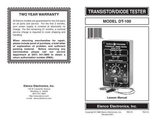
TWO YEAR WARRANTYAll Elenco <strong>model</strong>s are guaranteed for two full yearson all parts and service. For the first 3 months,your power supply is covered at absolutely nocharge. For the remaining 21 months, a nominalservice charge is required to cover shipping andhandling.TRANSISTOR/DIODE TESTERMODEL DT-<strong>100</strong>When returning merchandise for repair,please include proof of purchase, a brief letterof explanation of problem, and sufficientpacking material. Before returning anymerchandise please call our servicedepartment at (847) 541-3800 to obtain areturn authorization number (RMA).Elenco Electronics, Inc.150 W. Carpenter AvenueWheeling, IL 60090(847) 541-3800http://www.elenco.<strong>com</strong>e-mail: elenco@elenco.<strong>com</strong>Lesson ManualElenco Electronics, Inc.Copyright © 1988 Elenco Electronics, Inc. REV-D 753115Revised 2001
FEATURESDiode Mode:1. Checks all types of <strong>diode</strong>s - germanium, silicon, power, lightemitting (LEDs), and zener.2. Indicates the cathode or anode leads of the <strong>diode</strong>.3. Operates in circuit with resistors as low as 5kW.SCHEMATIC DIAGRAMTransistor Mode:1. Checks all types of <strong>transistor</strong>s - germanium, silicon, power, RF,audio, switching, and FETs.2. Identifies NPN and PNP types, PN or NP junctions.3. High gain circuit, can test <strong>transistor</strong>s in circuits with base orcollector resistors as low as <strong>100</strong>W.4. Measures relative beta of two <strong>transistor</strong>s.-1- -6-
DT-<strong>100</strong> PARTS LISTResistors 5% 1/4WQty. Symbol Value Color Code Part #1 R14 <strong>100</strong>W brown-black-brown-gold 13<strong>100</strong>02 R5, R6 220W red-red-brown-gold 1322002 R1, R10 330W orange-orange-brown-gold 1333001 R13 1kW brown-black-red-gold 14<strong>100</strong>01 R7 5.6kW green-blue-red-gold 1456001 R12 10kW brown-black-orange-gold 15<strong>100</strong>01 R8 18kW brown-gray-orange-gold 1518002 R2, R3 33kW orange-orange-orange-gold 1533001 R9 47kW yellow-violet-orange-gold 1547001 R11 <strong>100</strong>kW brown-black-yellow-gold 16<strong>100</strong>01 R4 330kW orange-orange-yellow-gold 1633001 R15 <strong>100</strong>kW Variable Potentiometer 192611CapacitorsQty. Symbol Value Description Part #1 C6 0.001mF (102) Discap 2310363 C2, C3, C5 0.01mF (103) Discap 2410312 C1, C4 10mF Lytic 271045SemiconductorsQty. Symbol Value Description Part #1 D1 1N4001 Diode 3140011 Q5 MPS A70 Transistor 3200704 Q1 - Q4 2N3904 Transistor 3239041 IC1 555 Integrated Circuit 3305555 L1 - L5 Light Emitting Diode 350002Qty. Description Part #1 PC Board 511<strong>100</strong>1 Switch Push Button 5400012 Switch DPDT 5411111 Battery Snap 5900981 Panel Front 614<strong>100</strong>1 Knob 6220091 Case 6232405 Spacer LED 6241114 Screw 4-40 x 1/4” 6414301 Nut Pot 7mm 6441011 Flat Washer 6451014 Nut 4-40 644400MiscellaneousQty. Description Part #1 Lockwasher 5/16” Int. 6461011 Socket 8-Pin IC 6640081 Transistor Socket 6645001 Clip Black 6800011 Clip Red 6800021 Clip Green 6800031 Clip Yellow 6800041 Wire Black 20 ga. 8131101 Wire Red 20 ga. 8132101 Wire Yellow 20 ga. 8134101 Wire Green 20 ga. 8135101 Wire Blue Solid 22 ga. 814620OPERATING INSTRUCTIONSThe DT-<strong>100</strong> is a dynamic <strong>transistor</strong> and <strong>diode</strong> <strong>tester</strong>. It features incircuittesting and polarity indicators for both <strong>transistor</strong>s and<strong>diode</strong>s. To activate the DT-<strong>100</strong>, remove the four front mountingscrews and install a fresh 9V battery.Diode Testing1. Place the switch in the <strong>diode</strong> position.2. Connect the <strong>diode</strong> to the red and black leads.3. Push in the test switch. One <strong>diode</strong> LED should blink and identifywhether the cathode or anode is connected to the <strong>diode</strong> (red) lead.4. If both LED lamps blink, then the <strong>diode</strong> is shorted.5. If neither LED lamps light, then the <strong>diode</strong> is open.Transistor Mode:The DT-<strong>100</strong> can measure <strong>transistor</strong>s in or out of circuit.identify NPN or PNP by a simple adjustment.Transistor Testing - Out of Circuit1. Place the switch in the <strong>transistor</strong> position.It will2. Place the <strong>transistor</strong> in the socket or attach it to the C, B, and Eleads.3. Push in the test button. Adjust the base current control so thatthe OK LED lights up. This indicates a good <strong>transistor</strong>.4. If the OK lamp doesn’t light, adjust the base current control sothat either the NP or PN LED lights up. This happens at theminimum or maximum position of the control setting. This willindicate <strong>transistor</strong> type. Place the switch to the NPN position ifthe NP lamp lights up, or place the switch to the PNP position ifthe PN lamp is lit.-5-5. If no lamps light up, then the <strong>transistor</strong> is open or we have notidentified the base lead. Repeat assuming another lead at thebase.-2-
6. When the <strong>transistor</strong> is shown to be OK, the base current controlgives an indication of <strong>transistor</strong> beta. The lower the settingrelative to another <strong>transistor</strong>, the higher the beta. Lamps NPand PN measure base current. Higher base current results in abrighter LED. It also indicates if current is entering or leavingthe base, thus, NP or PN respectively will light.Transistor Testing - In CircuitThe DT-<strong>100</strong> will test <strong>transistor</strong>s in circuit, provided the base biasingresistance is greater than <strong>100</strong>W. Simply follow the previousprocedure for testing out of circuit <strong>transistor</strong>s. Do not apply powerto the circuit of the <strong>transistor</strong> or <strong>diode</strong> under test. The DT-<strong>100</strong> willsupply the necessary power.CHECKING OUT YOUR TRANSISTOR/DIODE TESTERThe following is a simple procedure for testing your DT-<strong>100</strong>.Diode Operation:1. Place the switch in the <strong>diode</strong> position. Short the black and redleads together and push in the test button. The <strong>diode</strong> test LEDsshould alternately go on at about a 1Hz rate.2. Connect the red and black leads to any good <strong>diode</strong>. Only one LEDshould flash, identifying the red lead connection (anode orcathode). Reversing the leads should cause the other LED to flash.Transistor Operation:1. Place the switch in the <strong>transistor</strong> position. Short the yellow (B)and black (E) leads together. Press the test button. Vary thebase current control. The NP lamp should light with the switchin the NPN position and the PN lamp when the switch is in thePNP position.2. Place a known good <strong>transistor</strong> in the test socket with the Emitterin E, Base in B and Collector in C pins. Be sure none of theleads are shorting. Vary the base current control. The OK LEDshould light up. Note that on the NPN <strong>transistor</strong>, the NP lampalso will glow very slightly. This indicates the base current, an<strong>dt</strong>hus lower intensity. The base current control should beadjusted for the lowest setting with the OK lamp glowing.THEORY OF OPERATIONNote the schematic diagram on page 6. The test <strong>transistor</strong> in thiscircuit is an NPN. Adjusting the variable resistor will cause theNPN LED to light up indicating that the base current is flowing. Theoutput of the test <strong>transistor</strong> is fed to amplifiers Q2 and Q3. Theoutput of Q2 is feedback in phase to the base of the test <strong>transistor</strong>causing the circuit to oscillate. Part of the oscillations are fed to apower rectifier, Q5, which switches on the OK LED indicator.The design configuration is such that in-circuit <strong>transistor</strong>s can bemeasured, provided that the base and collector resistors aregreater than <strong>100</strong>W.When measuring PNP <strong>transistor</strong>s, the power supplied to the test<strong>transistor</strong> is reversed via the NPN/PNP switch. Therefore, the PNLED will light up.Varying the base current control will reduce the base current. Thelower the base current, the higher the gain of the <strong>transistor</strong> undertest. Comparative tests of two <strong>transistor</strong>s’ gain (beta), can bemade by observing the dial setting or the intensity of the base LED<strong>diode</strong>. The lower the setting with the PN LED lit, the higher thebeta of that <strong>transistor</strong>.On <strong>diode</strong> operation, power is applied to IC1. This causes thecircuit to oscillate at about a 1Hz rate. Placing a <strong>diode</strong> in serieswith the LED indicators will cause a current to flow, depending onthe direction of the <strong>diode</strong>. Thus, the red test lead will identify thecathode or anode of the <strong>diode</strong> via the LED readout. Transistor Q4reverses the current flow in this circuit.All types of <strong>diode</strong>s may be tested: Silicon, germanium, LEDs orzeners over 6 volts. Zener <strong>diode</strong>s under 6V causes the secondLED to glow at lower intensity, indicating that zener breakdown hasoccurred.-3--4-