Chapter 4: Activated Sludge Modelling - IqTMA-UVa
Chapter 4: Activated Sludge Modelling - IqTMA-UVa
Chapter 4: Activated Sludge Modelling - IqTMA-UVa

You also want an ePaper? Increase the reach of your titles
YUMPU automatically turns print PDFs into web optimized ePapers that Google loves.
Solving the Exponential ModelBy solving dX/dt = µX :X t = X 0 exp(µ(t - t 0 ))Or ln(X t /X 0 ) = µ(t - t 0 )Doubling time t ½ at which X = 2X 0 ?t ½ = ln2/µ4
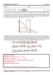
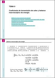
The Monod kinetic model = m S/(K s + S)r g = X = [ m S/(K s + S)]Xµ m = maximum specific growth rate (d -1 )K s = saturation or Monod constant (g l -1 )maxmax/2S = limiting substrate (g l -1 )r su = -r g /Y = X/Y = max SX/(Y(K s +S))KsSubstrate concentrationThe cell growth rate (and therefore the substrate removal rate) increaseswith the substrate concentration, up to a certain level when it stabilize at m . If the limiting substrate concentration is low: conditions of slow growth!5
Endogenous decayIf part of the biomass produced is degraded, r g = - Yr su is no longer true!With endogenous decay: r g = -Yr su – k d XWith k d = endogenous coefficient decay (d -1 )r g = Volumetric biomass production rate (g VSS/m 3 d)-Yr su = Rate of biomass production from substrate consumptionk d X = Rate of biomass consumption by endogenous respirationAnd = m S/(K s + S) - k dNote that r su is unchanged!!!!!r su = -r g /Y – k d X/Y = -Y -1 (X + k d X) = - max SX/(Y(K s + S))6
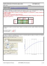
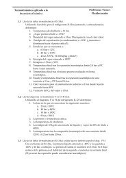
Other models: Maintenance Costsno maintenance requirementmaintenance requirementSubstrate concentrationMicroorganisms will not be able tomultiply at too low substrateconcentration as all the substrate isused for maintenance (or notdetected)Growth rateS concentrationThe growth rate drops when thesubstrate concentration is too highdue to cell inhibition. Examples ofinhibiting substrate are phenolics,acids, and oxygen.7
Continuous Treatment in wellmixed reactors (CSTR)Under a steady state in a well mixed reactor X = Xr and S = Sr (X and S = concentrations)Under a steady state dX/dt = dS/dt = 0This also means:Q(X – X o ) = P x = biomass production rateQX 0S 0VrXrrSrS rQXSQ(S o – S) = P s = substrate consumption rateVdX r /dt = cell in - cell out + cell produced = QX 0 - QX + r g VFor simplification, X 0 = 0 and by definition r g = µX XV=XQ = Q/VBy definition D = dilution rate = Q/V = µ = 1/HRT (Hydraulic RetentionTime): The growth rate is dictated by the dilution rate.8
S and X in CSTR (no decay)Monod model: µ = µ m S/(K s +S)Under steady state: µ = D, therefore D = µ m S/(K s +S)Solving this equation S = DK s /(µ m – D)S mass balance: VdS/dt = 0 = QS 0 – QS + r su V r su V = - Q(S 0 -S)Since r su V= (-r g /Y)V = - µVX/Y = -DVX/Y = -QX/Y (since D = Q/V) Q(S 0 – S) = QX/Y = DX = Y(S 0 – S)(This could have be obtained directly from the expression of the trueyield)9
ExerciseThe growth of a strain of Lactococcus lactis on a medium containingglucose as the growth limiting substrate is characterized by thefollowing parameters: µ m = 0.6 h -1 ; K s = 0.03 g L -1 ; Y = 0.3 g g -1The feed contains 1g L -1 of glucose. The culture is growing in a 5 LCSTR being fed at 2.75 L h -1 . Using the Monod model, calculate thesteady state values of the dilution rate, the hydraulic residence time,the glucose concentration (S) and the biomass concentration (X) in thereactor.Calculate X and S when:a. The dilution rate is changed to 0.3 h -1 and 0.6 h -1b. The substrate concentration is increased to 3 g L -110
SolutionBy definition D = Q/V = 0.55 h -1 and HRT = 1/D = 1.82 hUsing S = DK s /(µ m – D), S = 0.33 g L -1 and X = Y(S 0 -S) = 0.201 g L -1At D = 0.3 h -1 and S 0 = 1 g L -1 : S = 0.03 g L -1 and X = 0.291 g L -1At D = 0.6 h -1 : S = 1 and X = 0: washout!Conclusions: A CSTR cannot be operated at too high dilution rate,otherwise the cell do not grow fast enough to compensate the cell lost.The cell concentration rapidly drops and the process fails! Lower dilutionrates allow better efficiency but require higher reactor volume (atconstant flow).11
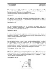
Maximum Dilution Rate: DmaxCell concentrationCell concentrationS1Output of cells DxS2SubstrateconcentrationmaxSubstrateconcentrationmaxDilution rateDilution rateCSTR: = D = Q/VAt washout condition: S = S 0 = D max K s /(µ m – D max )D max = m S 0 /(K s + S 0 ) = m /(1 + K s / S 0 )Cell wash-out occurs at too high dilution rates (D >D max ) and is especiallysensitive at low initial substrate concentration.12
Influence of endogenous decayNow = mS/(K s+S) – k dS: The biomass balance is identical, hence: D = = m S/(K s +S) – k d . Solving this equationgives: S = K s(D + k d)/( m– D – k d)S mass balance: VdS/dt = 0 = QS 0 – QS + r su Vr su = -r g /Y-k d X/Y = -X/Y-k d X/Y = -X(D + k d ) /YSolving this equation gives: X = YD(S 0– S)/(D + k d) = Y(S 0– S)/(1 + k d/D)D max is obtained for S = S 0 = K s (D + k d )/( m – D – k d )Solving this equation gives D max = m /(1 + K s /S 0 ) - k d13
Influence of nbVSSAn amount of non biodegradable, also called inert, VSS is introduced intothe reactor in the WW. This amount is not degraded biologically andtherefore, at a steady state, the nbVSS concentrations in the effluentand reactor are similar to the nbVSS concentration in the influent (X 0,i )The total mass of VSS in the Bioreactor includes the biomass produced(r g ), the nbVSS introduced (X 0,i ) and the debris released from theendogenous decay:QX 0S 0VrXrSrQXS14
Influence of nbVSSr VSS = total VSS production rate = r g + QX o,i /V + f d (k d )Xr g = -Yr su – k d X = biomass production from bCOD (-Yr su) minus endogenousdecay (k dX)f d (k d )X = rate of cell debris production with f d= fraction of biomass remainingas cell debris. The cell debris production is directly proportional to thebiomass concentration and k dQX o,i /V = Amount of nbVSS in the influent (Q = influent flow rate, X 0,i= influentnbVSS and V = reactor volume).15
Influence of nbVSSFraction of active biomass: F x,act = X/VSS = r g /r VSSIndicate how much of the VSS is “active” (serve to COD removal)Net biomass yield: Y = - r g /r suObserved yield: Y obs = - r VSS / r suFrom the COD balance:We assume the debris have asimilar composition to thebiomass, and the same CODequivalence of 1.42 g COD/g VSS= COD debrisO 2 -required = CODused – CODbiomass – CODproductsO 2 -required (kg/d) = Q(S 0 -S) – 1.42(r g + f d k d X)16
The activated sludgeprocess17
Biomass retentionCell washout is more likely to occur:At low temperatureAt low substrate concentrationAt too high flowWhat can be done to prevent it?Large reactors: $$$Harvest and recycling: activated sludgeImmobilization: biofilmBiomass retention is almost always needed during WWT:Large flow rates continuous processesLow COD concentrations continuous processes risk ofwashout!This is not the case for small WWT!18
<strong>Activated</strong> sludge19
AerationSurfaceDiffused$$$ Aeration consumes up to60% of electricity in a WWTP!20
Secondary clarifierUse of classical clarifierVery important part of the process: thesludge must have the best settleabilitypossible, measured by the <strong>Sludge</strong>Velocity IndexSVI( Settled Volume of<strong>Sludge</strong> in 30 min, ml ) (1000L( X ,mg)Lmgg)mLg21
Many configuration possible!The A2/O process22
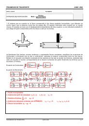
<strong>Activated</strong> sludge designFeedQ 0, X 0, S 0Aeration tankQ, X, SClarifierEffluentQ e, X e, S eRecirculationQ r, X r, S rWasteQ w, X w, S w23
OverviewApplicationCostsAdvantagesDisadvantagesOrganic chemical, textile, municipal sewage,steel, pulp and paperOperating 0.16 - 0.8 $ /m 3 , capital 500 - 1,900 $/(m 3 -d) for flow rates of 100 - 1,000 m 3 /dSimple to start up and operate, manyconfigurationsHigh sludge production, dependent on settlingOrganic loading0.3 - 3 kg BOD/(m 3 -d)HRT4 - 8 h (municipal)BOD removal85 - 95% (municipal)Source: Environmental Biotreatment. CN Mulligan.This is given as an example only, very specific of North America24
OverviewDissolved O 2> 2 mg/L; DO > 4 mg/L increase aeration costsQ w4000-12000 mg/LQ r /Q 00.5-0.75<strong>Sludge</strong> blanketHeight (º/ 1 )0.1Typical OperationProblem<strong>Sludge</strong> bulking due to the growth of filamentousbacteriaSource: Environmental Biotreatment. CN Mulligan.This is given as an example only, very specific of North America25
Solid Retention Time (SRT)The SRT is defined as the average time the solids stay inside theaeration tank. When VSS = active cells (X), the SRT is also calledMean Cell Retention Time (MCRT) with:SRT =Amount of active biomass in the systemProduction rate of active biomassAmount of active biomass = VX (kg)The production rate can be obtained from the biomass mass balanceunder steady state as X out – X in = Production withXout = Q e X e + Q w X wXin = Q 0 X 0SRT for BOD removal 3 day at 18-25 ºC or 5-6 at 10 ºC26
Solid Retention Time (SRT)Total biomass in the reactorSRT =VX(Q eX e+ Q wX w) – Q 0X 0VX(Q eX e+ Q wX w)outinAmount of sludge “wasted”Note X r = X wOften X w >> X e and Q w X w + Q e X e Q w X wOther name of SRT: <strong>Sludge</strong> Age27
Expression of SBiomass balance:VdX/dt = 0 = Q 0 X 0 - (Q e X e + Q w X w ) + Vr g (Q e X e + Q w X w ) - Q 0 X 0 = VµXFrom the definition of SRT:(Q e X e + Q w X w ) - Q 0 X 0 = (Q e X e + Q w X w )= VX/SRT 1/SRT = µµ = µ m S/(K s + S) – k dS = K s (1 + (k d )SRT)/(SRT(µ m – k d ) – 1)28
Expression of XX can be obtained from S mass balance:VdS/dt = Q 0 S 0 – (Q e S e + Q w S w ) + r su V = 0With the assumptions that S = S w = S e = S r (S = bsCOD) and since (Q e+ Q w) = Q 0 , this becomes:Q 0 (S 0 – S) = -r su VSince r g = -Yr su – k d X; r g = µX = X/SRT and HRT = V/QX = (SRT/HRT) Y(S 0 – S)/(1 + (k d )SRT)29
Total mixed liquor VSS (MLVSS)MLVSS = active biomass + inert nbVSS = (X) + (X i )X i = X 0,i (nbVSS introduced) + X d (concentration of cell debris in thereactor)Q 0 , X 0,iQ r , X r,iX iQ e , X e,iQ w , X w,iMLSS = Mixed Liquor TSS30
Solids production rateP MLVSS = r g V (active X) + r d V (debris) + QX 0,I (nbVSS) = [kgVSS/d]r g = µX = X/SRT with X= (SRT/HRT)Y(S 0 – S)/(1+ k d SRT)r d = cell debris production rate = f d k d XQX 0,i = amount of nbVSS introducedP MLVSS = QY(S 0 – S)/(1 + k d SRT) + f d k d XV + QX 0,iRemember the solid fraction in made of active biomass, cell debris andan inert VSS introduced from the influent. The last 2 fractions willimpact process efficiency because larger settler and reactor tank willbe needed.During wastewater treatment, one must also add the solid fraction dueto inorganics.31
..and if we have nitrification??P MLVSS= r gHV (Heterotrophic X) + r gNV (Nitrifying bacteria) + r dV (debris) +QX 0,I(nbVSS)O 2required = Q 0(S 0-S) - 1.42 (P XBio) + 4.33Q [NO 3-]where P XBio= Production of Heterotrophic and nitrifying Biomass and celldebris Production[NO 3-] = [TKN] - [N effluent] - [Nitrogen assimilated] = [TKN] - [N effluent] -0.12P XBio32
Processes for BOD Removal andNitrificationHeterotrophic MicroorganismsNitrifying MicroorganismsParameter ( T20ºCmax; Ks;Kd) Parameter ( max;Ks;Kd)T 2033
Processes for BOD Removal andNitrificationComputational Step for a correct Design of an AS process:1. Wastewater Characterization (bCOD, nbVSS, etc.)2. Effluent requirements [N-NH 4+], TSS, bCOD3. Nitrification safety factor (normally peak/average TKN loading ratio)4. Select a design DO in the aeration basin (typically 2 mg/L)5. Determine the specific growth rate for nitrifyiers, that due to their lowgrowth control AS design, based on DO and effluent [N-NH 4+]n nmN Kn NKoDO kDO6. Obtain the SRT corrected by the safety factor7. Obtain the effluent bCOD from Heterotrophic GrowthdnSRT1nS = Ks(1 + (k d)SRT)/(SRT(µ m– k d) – 1)34
Processes for BOD Removal andNitrification8. Determine Biomass Production (P XBio). Estimated NO 3-as 80 % TKNPXBioQY( So S)fdkdQY( So S)SRT QYn( NO3)1k SRT 1k SRT 1k SRTddnd9. N balance to calculate NO 3-(Find the real NO 3-production based onthe N removed during biomass growth)10. Calculate the TOTAL VSS and TSS mass in the aeration basinP MLVSS= r gHV (Heterotrophic X) + r gNV (Nitrifying bacteria) + r dV (debris) +QX 0,I(nbVSS)P MLSS=[ r gHV (Heterotrophic X) + r gNV (Nitrifying bacteria) + r dV (debris) +QX 0,I(nbVSS)]/0.85 + Q (TSS o-VSS o)11. Select a design MLSS concentration (Typically 2500-3500 mg/L for agood settler performance) and determine the aeration volume andHRTX VSSV = (P MLVSS)SRT35
Processes for BOD Removal andNitrification12. Check alkalinity Balance:Alkalinity to maintain pH at 7 (typically 80 mgCaCO 3/L) = Influent Alk –Effluent Alk – Alk consumed (typically 7.14 g CaCO 3/g N-NH 4+)13. Design secondary clarifier (chapter 6) Area based on desktopdesign approach or model based Xr RAS flow rateQ + Q rXQ rX rQX e 0QrXrQrR Q ( Q Q ) XRAS R XrrX X36
Processes for BOD Removal andNitrificationProcess Configuration for BOD Removal Exclusively• Suitable when space is limited• When nitrification is not needed to meet treatment discharge limitsA) High purity oxygenSRT 1- 4 days / HRT 1-3 h• O 2absorption 2-3 times greaterthan conventional AS• Enclosed systems• Higher MLSS and Organicloading rates• Shorter HRT Low reactor V• Inhibition of Nitrification due toCO 2accumulation low pH• High Invest and Operation Costs37
Processes for BOD Removal andNitrificationB) High Rate Aeration Systems.SRT 0.5 - 2 days / HRT 1.5-3 h• Systems operated at High loading rates, low MLSS concentration, andlow HRT• Less stable operation, lower quality effluent, High <strong>Sludge</strong> Production38
Processes for BOD Removal andNitrificationProcess Configuration for BOD Removal and NitrificationA) Complete Mixed systemsSRT 3 - 15 days / HRT 3-5 hAdvantage: Dilution of shock loads / Simple operationDisadvantage: Promotes the development of filamentous Bacteria39
Processes for BOD Removal andNitrificationB) Plug Flow3 to 5 channels usedDifficult to match BOD andaeration thoughout wastewatermovementProven efficiency!!SRT 3 - 15 days / HRT 4-8 h40
Processes for BOD Removal andNitrificationC) Step feed plug flowWastewater introducedin 3 to 4 pointsSRT 3-15 days / HRT 3-5 hOrganic load is provided uniformly easier to match with O 2supplyDisadvantage: More complex operation than conventional plug flow41
Processes for BOD Removal andNitrificationD) Low-Cost Systems: operated at long SRT High Tank VolumesSuitable for Small communities where land is not a limitationSRT 15-40 days / HRT 15-30 hE) Sequential Batch SystemsOnly 1 bioreactor used3 h fill 2 h aeration 0.5 h settling 0.5h withdrawal2 bioreactors operated simultaneouslyNo need for secondary settlerSRT 10-30 days / HRT 15-40 h42
Processes for Biological NitrogenRemoval4 main categories:• Preanoxic configuration: Wastewater and RAS meet in the Preanoxictank. Nitrate is recycled from the aerobic compartment. Electron donor isinfluent BODRate of Denitrification affected by rbCOD, [MLSS], and T• Postanoxic Configuration: Anoxic zone follows aerobic zoneThe electron donor can be either an external Csource (typically methanol) or lysis substratefrom endogenous respiration of activatedsludge (in this last case denitrification is 3-8times slower than preanoxic denitrification43
Processes for Biological NitrogenRemoval• Simultaneous Nitrification and Denitrification:It requires an strict DO controlIt has been observed in reactorswith long SRT• Two-sludge process: A first step for BOD removal and nitrification and asecond one for denitrification (supplemented with an external e- donor)44
Processes for Biological NitrogenRemoval: Preanoxic TreatmentThe most common Configuration is the Preanoxic Treatment because:• Easy retrofit of exiting plants originally designed for BOD removaland Nitrification• Benefits from the selector (anoxic zone) to avoid bulking• Production of alkalinity before nitrificationTwo Types of Preanoxic Configuration:Single FeedStep-Feed45
Processes for Biological NitrogenRemoval: Preanoxic TreatmentKey design parameters of Anoxic/Aerobic reactors:• Anoxic HRT• [MLSS]• Internal Recycle and RAS• [bCOD]• [rbCOD]• TemperatureTwo design approaches:1- Nitrogen mass balances and the parameter SDNR (g N-NO 3-reduced/ gMLVSS d)2- ASM models46
Processes for Biological NitrogenRemoval: Preanoxic TreatmentSpecific Denitrification Rate (SDNR)• The amount of nitrate removed in the anoxic tank is:NOx Vwhere VanoxanoxSDNR specific denitrification rate (g N - NOMLVSS (g/m SDNR [MLVSS],is anoxic3)tank volume (m3)-3SDNR SDNR20 1.026/g MLVSS d)In full-scale facilities SDNR range from 0.04–0. 42 g N-NO 3-/g MLVSS d( T 20)SDNR is a function of: Temperature ( ) ratiorbCOD/bCOD, and the F/M bratio defined as the ratio of the influent BODloading rate to Active Heterotrophic BiomassF / MbQ SoV XanoxbNote: Active biomass X b is calculated as described in the BOD removal and nitrification section47
Processes for Biological NitrogenRemoval: Preanoxic TreatmentSDNR is also affected by the internal recirculation (IR, typically 3-4) if F/M bis > 1IR 2 SDNRadjIR 34 SDNRadjSDNRIR1SDNR 0.0166ln( FMIR1 0.029ln( FMb) 0.0078b) 0.01248
Processes for Biological NitrogenRemoval: Preanoxic TreatmentComputational Steps for a correct Design of an Anoxic/Aerobic process:1. Determine wastewater characteristics (emphasis in rbCOD/bCOD ratio)and effluent requirements2. Determine the SRT from the procedure established for nitrification designnX N nmKnN KbQ SRT Y S V 1koDO kDOod S SRT dn1SRT3. Determine the active biomass concentration for the nitrification design4. Determine IR using the NOx concentration previously determined from theN balance in the nitrification design and the desired N-NO 3-in the effluent-kg/d of NO3producedin the aerobic zoneQ NO Ne Q IR Q R Q-- NO 3in the NO3 effluent IRin theNO3in the RAS3-49
Processes for Biological NitrogenRemoval: Preanoxic Treatment5. Calculate the amount (kg/d) of nitrate fed to the anoxic tank. The designin based on the assumption that all the nitrate fed is reduced.6. Select an anoxic tank HRT (typically 2.5 h) V Anox(Based on Q o)7. Calculate de F/M bbased on the biomass calculated in the nitrificationdesign (X b)8. Estimate SDNR based on the F/M band rbCOD/bCOD ratios (Fig 8-23 inMetcalf & Eddy, 2003). Correct for T and IR9. Using the SDNR adjand the V Anoxselected in step 6 calculate the potentialNO 3-removed. Compared with the amount calculated in step 510. Repeat the procedure from step 6 by selecting a higher or lower V Anox.11. Check alkalinity Balance:[Alkalinity to maintain pH at 7 (typically 80 mgCaCO 3 )] = [ Influent Alk] + [Alkproduced (typically 3.57 g CaCO 3 /g N-NO - 3 reduced)] – [Effluent Alk] – [Alkconsumed (typically 7.14 g CaCO 3 /g N-NH + 4 oxidized)]50
Processes for Biological NitrogenRemoval: Postanoxic TreatmentPostanoxic denitrification can be performed using activated sludgeendogenous respiration. SDNRs range from 0.01-0.04 g N-NO 3-/g MLVSS dTreatment following nitrification (bCOD has been fully depleted)1.42SDNRb kd 0.5kd;where kd2.86decay coefficient andthe fraction ofisthe biomass endogeneousdenitrifying biomassSDNRSDNRSDNRbbbis afunction of 012 . SRT SDNR20º Cb0.706SRT1.08( T 20)51
Processes for Biological NitrogenRemoval: Post-anoxicPost-anoxic denitrification can be carried out in a two-sludge processusing an external C source (typically methanol)An SRT of 5 days is normally used. Effluent N < 3 mgN/LThe anoxic tank is followed by a short aeration time of 10-20 min torelease the N 2bubbles entrapped in the MLVSSHigh operation costs!!!The process is designed based on methanol denitrification kinetics52
Processes for Biological NitrogenRemovalComputational steps for a correct design of a postanoxic process withexternal C source addition1. Determine the amount of N-NO 3-to be removed Q([NO 3-influent] – [NO 3-effluent])2. Select an anoxic tank SRT (typically 5 d)3. Calculate the residual methanol concentrations in the effluentS = K s(1 + (k d)SRT)/(SRT(µ m– k d) – 1)4. Calculate the methanol dose (methanol required for N-NO 3-reduction +methanol in the anoxic tank effluent[CH 3OH] required= bCOD + [CH 3OH] effluent= 2.86[N-NO 3-]/(1-1.42Y n)+ [CH 3OH] effluentin gram of COD/m 35. Calculate the total amount of methanol required = Q [CH 3OH] required6. Calculate the TSS productionP MLSS=[ r gHV (Heterotrophic X) + r gNV (Nitrifying bacteria) + r dV (debris) +QX 0,I(nbVSS)]/0.85 + Q (TSS o-VSS o)7. Determine the V Anoxfrom the TSS production and SRT53
Processes for Biological NitrogenRemoval: Process configurationA) Modified Ludzack Ettinger • Energy savings in aeration bythe use of NO 3-for BOD removal• Saving in alkalinity addition• 5-8 mg N e/L are possible• Potential problems of bulkingSRT 7-20 d; HRT anox1-3 h; HRT aer4-12 h; IR 2-4B) Step feed MLE• The above mentioned advantages• Take advantage of the highMLVSS in the first stages• 5-8 mg N e/L are possible• Potential problems of bulking54
Processes for Biological NitrogenRemoval: Process configurationc) Sequential Batch Reactor• Denitrification during filling,settling and decant periods•5-8 mg N e/L are possible• Redundant units and complexoperationSRT 10-30 d; HRT anox &HRT aervariable (total 20-30 h)d) Oxidation ditch, NitroxTM• Large HRT (20-30 h) and longSRT 20-30 d• N e< 10 mg N /L are possible• Resistant to shock loads55
Processes for Biological NitrogenRemoval: Process configurationE) Bardenpho • Simultaneous P & N Removal• N e < 3 mg N /L• Large Reactor VolumesSRT 10-20 d; HRT anox 1-3 h 1 st stage 2-4 h 3 rd stage HRT aer(4-12 h 2nd stage and 0.5-1 h 4 th stage)E) Orbal TM (Simultaneous N/DN• 1 st channel DO < 0.3 mg/L; 2 nd channel 0.5 < DO
Processes for BiologicalPhosphorous RemovalBased on a sequence of an anaerobic P releasing step followed by anaerobic P uptake stepKey Design Considerations:1- Wastewater Characteristics: rbCOD is the most important parameterrbCODAcetate & Propionate7–10 mg Acetate/mg P removedPHB for energy andgrowth in aerobic andanoxic stagesP releasedduring uptakeCompetition of Denitrifyiers and PAOs for rbCODContinuous VFA supply from primary sludge fermentation is beneficial inBPR57
Processes for BiologicalPhosphorous Removal2- Anaerobic Contact Time: periods of 0.25 to 1 h are sufficient forrbCOD fermentation. Too long contact times (> 3 h) result in secondaryP release not associated to PHB accumulation3- SRT. Long SRT bring about lower P-REs due to:a)- at high SRT less PAO biomass is producedb)- at high SRT PAOs are in a more extended endogenousphase, consuming their intracellular storage products.4- Waste sludge Processing. The use of gravity thickeners for sludgeconcentration might result in a significant release of P that is recycled tothe process.5- Chemical precipitation might be needed when insufficient amounts ofrbCOD are present in the influent wastewater.58
Processes for BiologicalPhosphorous RemovalMethods to enhance BPR.1- Provide supplemental acetate by direct purchase or by primary sludgefermentationVFA2- Reduce SRT3- Add alum or Fe salts in primary treatment (Fe salts remove malodours)4- Reduce the amount of Nitrate or O 2entering the anaerobic zone59
Processes for BiologicalPhosphorous Removal5 Processes most commonly used: A/O TM , A 2 /O TM , UCT, Phostrip, andModified BardenphoA) A/O TM .• It does not include nitrification (limited by short SRT)• Very simple operation• HRT anaerobic 0.5-1.5 h (higher HRT cause a secondary P released) and1-3 h in the aerobic zone• SRT 2-5 d60
Processes for BiologicalPhosphorous RemovalB) A 2 /O TM: Suitable for weak Wastewaters (low bsCOD)• Simple operation• Anoxic Zone for DN• Energy savings and Alk production• Need for a high BOD/P ratio• IR 1-4SRT 5-25 d; HRT anae0.5- 1.5 h; HRT anox0.5-1 h; HRT aer4-8 hC) University of Capetown (UCT): Suitable for weak wastewaters (low bsCOD)• Minimize the effect of NO-3 inbsCOD removal in the anaerobicstage• RAS to the Anoxic Tank and IR fromthe anoxic to the anaerobic• IR 2-4SRT 10-25 d; HRT anae1-2 h; HRT anox2-4; HRT aer4-12 h61
Processes for BiologicalPhosphorous Removal• Modified UCT process offers ahigher protection of theAnaerobic tank against thepernicious effects of Nitrate• More complex operationd) PhoStrip: Combined biological and chemical P removal• No N removal• P is released from Biomass in ananaerobic gravity settler receivingRAS• Overflow from the settler is treatedchemically with alum, lime or Fe salt•The RAS is returned to the aerobicstage62
Processes for BiologicalPhosphorous Removal☺ PhoStrip can be easily incorporated in existing AS plants☺ It can achieve [Ortophosphate] < 1 mg/L☺ Less dependent on bsCOD☻ High operation cost due to chemical use.☻ High maintenance when using LimeSRT 5-20 d; HRT anae8-12 h; HRT aer4-10 hE) Modified Bardenpho• The second anoxic stageprovides additional nitrificationRAS free of Nitrates• 3-5 mg/TN• Less efficient for P removal• Large Tank Volumes63
<strong>Activated</strong> <strong>Sludge</strong> ModelingASM nº164
ASM nº1• Characteristics• Developed in 1987 (Henze et al., 1987)• Presented in a matrix format• Incorporates• Carbon oxidation• Nitrogen removal• Nitrification / Denitrification• Particulate matter Hydrolysis• Alkalinity CheckPhosphorous Removal was later described in model ASM2, ASM2d,ASM3Target parameters: <strong>Activated</strong> <strong>Sludge</strong> Concentration & ElectronAcceptor requirements!! (Not Substrate concentrations!!65
Biological reaction kineticsMicroorganisms decay:• Considered as 1 st order kineticsRate ofdecay bX• Physiological aspects described by decay: cell lysis andendogenous respiration and predationEnvironmental factors (organic substrate, O 2, etc..) that affect growth:Required substances: Modelled as switching functions thatactivate or deactivate reactions if the substance is present orabsent:SKOOK SK SOOGrowth Rates are described by simple Monod KineticsArrhenius functions: to show the influence of environmentalfactors such as TOO66
ASM StructureDefinitionsThe model is presented in a matrix format (Petersen matrix)ComponentXbSsSoProcess rateProcess ↓1 Growth1-1/Y(1-Y)/Y·Ss·Xb/(Ks+Ss)2 Decay-1-1b·XbComponents: (column) All the substances involved in transformations(processes)Processes : (rows) Transformations that take place in the system• Stoichiometric coefficients (relationship between components)• Kinetic expressions (rate equations for processes)67
Model presentationMASS BALANCES:• Basic equation for mass balances (in terms of COD)• Input – Output + Reaction = Accumulation Input and Output are transport terms and depend on the systems (e. j. Q xS s) Reaction term for each component obtained by summing the products:r i jand jij wherejthe reaction rates ofijare the stoichiometric coefficientseach particularprocess• The partial derivative for the component will be the sum of biologicalreaction effects and the effects from input and outputs68
Model Presentation• Continuity check• In the transformations there are not unbalances in mass orelectric charge.• This mass conservation can be easily checked in the matrix:The sum of the stoichiometric coefficients for eachtransformation (process) must be zero (consistent units)Remember that Oxygen COD is negative (thestoichiometric coefficient must be multiplied by -1!!69
Components in ASM1Organic matter characterization:Units (COD)Division of different substrates based on biodegradabilitySoluble/particulate (assumptions)total CODCODbiodegradableCOD nonbiodegradableS SX S X OS IX I70
Components in ASM1Nitrogen Characterization (components)N totalKjeldahl (TKN)NitratesS NOAmmonia NlS NHOrganic NOrganic NsolubleOrganic NparticulateNon biodegradableS NIBiodegradableS NSNon biodegradableX NIBiodegradableX NSComposition of N in active biomass 0.086 gN g Cell-CODComposition of N in biomass debris 0.06 gN g Cell-COD71
Components in ASM172
Components in ASM1• The i = 13 column represents Alkalinity• It provides an indication of the buffer capacity of thewastewater• The balance must include all the reactions thatinvolve addition or removal of species with protonaccepting capacity• Nitrification tend to decrease and denitrification toincrease• Risk of pH instability at alkalinities < 50 g CaCO 3 /m -3• Lime addition is often use to maintain the pH73
Processes in ASM1Biological processesj Process1 Heterotrophic aerobic growth2 Heterotrophic anoxic growth3 Autotrophic growth (Nitrification)4 Heterotrophic decay5 Autotrophic decay6 Ammonification7 Organic matter hydrolysis8 Organic nitrogen hydrolysisBiomass GrowthBiomass decayAmmonification of organic NOrganic Matter Hydrolisis74
Processes in ASM1ORGANICNITROGENSOLUBLEORGANICNITROGENPARTICULATESOLUBLEINERTSUBSTRATESUSPENDEDINERTSUBSTRATES NSX NSS IX IAMMONIANITROGENS NHNITRATESS NOAUTOTROPHICBIOMASSSOLUBLE INERTNITROGENS NIX BAREADILYBIODEGRADABLESUBSTRATEHETEROTROPHICBIOMASSDEBRISFROMBIOMASSNo interactionS SX BHX OSLOWLYBIODEGRADABLESUBSTRATENitrogen RemovalX SOrganic Matter Removal75
Organic Matter BiodegradationORGANICSOLUBLENITROGENORGANICPARTICULATENITROGENINERTSUBSTRATESOLUBLE S IINERTSUBSTRATESUSPENDEDS NSX NSX IAMMONIANITROGENS NHNITRATESS NOAUTOTROPHICBIOMASSX BAINERT SOLUBLENITROGENX NIREADILYBIODEGRADABLESUBSTRATES Sρ 7SLOWLYBIODEGRADABLESUBSTRATEHETEROTROPHICBIOMASSXρ BH1ρ 4DEBRISFROMBIOMASSX OX S76
Organic matter biodegradationAerobic growth of heterotrophic biomass (ρ 1 )COD-BalanceSs( 1Y) S i S Y X (1 Y) COHoXBNHHBHH2SOSS XB HSN H SA LK YH 1 1iX B1 iX B YHYH1 4 1 HKSSSSSKO HSOSOXB HSwitching functionAssumptions:(deactivation at low DO)• Type of substrate (S S ). No non-growth associated S S storage• Relationship between catabolic and anabolic reactions (Yield)• N consumption for growth (and associated alkalinity)77
Organic matter biodegradationAerobic Growth of heterotrophic biomass: Monod Kineticsˆ H1 ˆ2HH ˆHSSK SSSK SS S H: Heterotrophic biomass growth rateˆ H: Maximum specific rate for heterotrophic biomassK S : Half saturation constantIt provides and indication ofthe affinity of the biomassfor the substrateReadily biodegradable material (rbCOD = S S) is the only substrateParticulate matter must undergo a hydrolysis step before uptake78
Organic matter biodegradationSlowly biodegradable substrate hydrolylis (ρ 7 )XSSS 11 7khKX X XSBHXXSBH KOHSO SO hKKOHOH SO KNOSNO SNO XBHAssumptions:Extracellular (enzyme dependent: Xs/X BH ).Takes place both in aerobic and anoxic conditions (but at different rates)79
Organic matter biodegradationSlowly biodegradable substrate hydrolysis (ρ 7 )Two empirical facts:• A) The rate is a first order reaction with respect to the active biomass• B) The rate saturates when the amount of Xs entrapped is largeK H½ K HKHXS/ XBHK X / XXSBHK XXS / X BHThe introduction of Xs introduces a time delay in the consumption of80electron acceptor
Organic matter biodegradationHeterotrophic biomass decay (ρ 4 )X BH1X OfPXSXNS1 fPiXBfPiXB 4 b H X BHAssumptions:• Biomass decay results in slowly biodegradable material (X S) and inertparticulate material (Xo)• Biomass decay is not coupled to electron acceptor utilization (this would resultin four equations with a large number of switching functions)• Biomass decay accounts for predation, lysis and energy maintenance81
NitrificationNitrification KineticsORGANIC SOLUBLENITROGENρ 6S NSAMMONIANITROGENS NHρ 8PARTICULATEORGANICNITROGENX NSINERTSOLUBLESUBSTRATEρ 3 NITRATESS NOAUTOTROPHICρ 3BIOMASSX BA ρ 5S IINERT SUSPENDEDSUBSTRATEX IINERT SOLUBLENITROGENs NIREADILYBIODEGRADABLESUBSTRATES SHETEROTROPHICBIOMASSX BHPARTICULATEORGANICINERTX OSLOWLYBIODEGRADABLESUBSTRATEX S82
NitrificationAerobic growth of autotrophic biomass (ρ 3 )X SBANHSNOSO1 1 4.571 iXBYYAY AAYAiXB14SALK71 YA 3 AKNHSNH SNH KOASOSO XBAThe oxygenequivalence for NH 4+Characteristics:Not depending on organic matter (autotrophs)Single step nitrificationAlkalinity and oxygen consumption83
NitrificationAutotrophic biomass decay (ρ 5 )Modeled in the same way as Heterotrophic Biomass decayXBAXP 1fPXSXND1 fPiXB fP iXB 5bA X BA84
NitrificationOrganic Particulate Nitrogen Hydrolysis (ρ 8 )XNSS NS 11 8khKX X SX BH X XSBHKOHS OSOh KK OHOHSO KNOSNOSNOXBHXXNSSRate associated to organic matter hydrolysis.85
NitrificationSoluble organic N ammonification (ρ 6 )S NHS NSS ALK1 -1 1 14 6 ka SNSXBHCharacteristics:First order kineticsUncoupled to any biodegradation process.Alkalinity release (charge balance)86
DenitrificationDenitrification kineticsORGANIC SOLUBLENITROGEN S NSORGANICPARTICULATENITROGENSOLUBLE INERTSUBSTRATES ISUSPENDED INERTSUBSTRATEX IX NSAMMONIANITROGENS NHNITRATESS NOρ 2AUTOTROPHICBIOMASSX BASUSPENDED INERTNITROGENX NIREADILYBIODEGRADABLESUBSTRATEHETEROTROPHICBIOMASSPARTICULATEORGANICINERTS SX BHX OSLOWLYBIODEGRADABLESUBSTRATEX S87
DenitrificationHeterotrophic Biomass Anoxic Growth (ρ 2 )XBHSS11Y HSNOSNHSALK1 YH YH i2.86 YXB14 2.86 YH1 iXBH14 2HKSSS SS K KOHOH SO KNOSNO SNO g XBHCharacteristics:Nitrates as electron aceptorAlkalinity release for charge balanceAssumption: not all biomass growth in anoxic conditions.88
Coefficients and parameters inASM189
Stoichiometric Matrix90
ConclusionsASM1 is a model for organic matter andnitrogen removal in activated sludgebiological reactorsSome constraints:Not valid for P removalExperimentally unable to estimate:• Difference between (X I ) and (X O )• Ammonification (not linked to organic matterdegradation)91
Conclusions• The Model works at constant T and pH• The composition of organic matter was assumed constantConstant stoichiometric coefficients• It does not account for N or P limitations• Constant distribution of heterotrophic populations• The type of electron acceptor does not affect biomass decay• The Model does not consider biomass settling (SRT > 3 days)• Biomass concentration should range between 750 and 7500 mg/Lto avoid settling problems• The unaerated fraction of the reactor should not exceed 50 % toavoid a deteriorated biomass settling92
In BioWin3Biowin 3 allows to simulate AS processes in CSTR.Bioreactor0Either DO (typically 2 mg/l) or air supply ratecan be set. Aeration by air diffusionT of operation is also requiredTypical Power requirements for maintaininggood mixture range from 20 to 40 W m -3MediaBioreactorAn inert support for biofilm attachment isused. This element requires:• Specific area of the carrier• Specific Volume of the carrier• % of reactor filled with carrier• Number of layer constituting the carrier• Boundary layer thickness93
In BioWin3Bioreactor Brush aeratorSimilar to a regular bioreactor but aerationis provided via superficial brush aerator.Power supply rate is used instead of airsupply rate.Similar to a regular bioreactor but aerationis provided via superficial agitation. Powersupply rate is used instead of air supplyrate.94
In BioWin3Sequencing Batch ReactorCycle setting must be introducedPost anoxic Denitrification can be simulatedMethanol influent element that requires:• Methanol concentration• Input type: Constant or variable (time scheduled)95