SenseAir S8 - Sensors Tecnics, Honeywell
SenseAir S8 - Sensors Tecnics, Honeywell
SenseAir S8 - Sensors Tecnics, Honeywell

You also want an ePaper? Increase the reach of your titles
YUMPU automatically turns print PDFs into web optimized ePapers that Google loves.
Gas and Air <strong>Sensors</strong>Product Specification®<strong>SenseAir</strong> <strong>S8</strong>Miniature CO2 sensor safety switch
Key technical specificationItem<strong>SenseAir</strong> ® <strong>S8</strong>Target gas CO 2Operating PrincipleNon-dispersive infrared (NDIR)0.04 to 2% volume CO 2 (Note 1)Measurement rangeUp to 3.2% volume CO 2 extended range (Note 2)Accuracy +-0.02% volume CO 2 +-3% of reading (Notes 3 and 4)Response timeOperating temperature2 minutes by 90% for diffusion sampling method model0 to 50C (Sensor works from -20C but values valid only for 0-50C)Operating humidity 0 to 85% RH non condensed (Note 5)Storage temperatureDimensions (mm)WeightPower supplyPower consumptionSensor lifeSerial communication-40º to + 70º CArticle no: 004-0-0050 32.7 x 19.7 x 9.9Article no: 004-0-0051 33.3 x 19.7 x 9.9< 8 grams5V ±5% unprotected against surges and reverse connection300 mA peak, 30 mA average, configurable15 years in normal commercial environmentsUART, Modbus protocolPWM output, 1 kHzAlarm_OCDirection control pin for direct connection to RS485 transceiver integrated circuit.0 to 100% for 0-20 000 ppm; 3.3V push-pull CMOS output, unprotectedAlarm state openCO 28500/6500 ppm, Normally conducting max 100mA. Transistor open at CO 2 High, ORPower Low, OR at Sensor FailureTable 1. Key technical specification for the <strong>SenseAir</strong> ® <strong>S8</strong>__________________________________________________________________________________________Note 1: Sensor is designed to measure in the range 0 to 32000 ppm with specified in the table accuracy. Nevertheless exposure toconcentrations below 400 ppm may result in incorrect operation of ABC algorithm and shall be avoided for model with ABCon.Note 2: Sensor provides readings via UART in the extended range but the accuracy is degraded compared to specified in the tableone.Note 3: In normal IAQ applications. Accuracy is defined after minimum 3 weeks of continuous operation. However, some industrialapplications do require maintenance. Please, contact <strong>SenseAir</strong> for further information!Note 4: Accuracy is specified over operating temperature range. Specification is referenced to certified calibration mixtures.Uncertainty of calibration gas mixtures (+-2% currently) is to be added to the specified accuracy for absolute measurements.Note 5: Specification provides operating conditions 100% tested in production. Normally sensors shall operate at 0..95%RH and0..50C temperature range
Absolute maximum ratingsStress greater than those listed in Table II may cause permanent damage to the device. These ratings arestress ratings only. Operation of the device at any condition outside those indicated in the operationalsection of these specifications is not implied. Exposure to absolute maximum rating for extended periodsmay affect device reliability.ParameterMinimum Maximum UnitsAmbient temperature under bias -40 85 CVoltage on G+ pin with respect to G0 pin -0.3 5.5 VMaximum output current from active output pin -25 +25 mAMaximum current on input -5 +5 uATable 2. Absolute maximum ratings specification for the <strong>SenseAir</strong> ® <strong>S8</strong>Sample gas diffusion areaDiffusion areaFigure 2. Diffusion areaPin assignmentG+G0Alarm_OCPWM 1kHzDVCC_outUART_RxDUART_TxDUART_R/TbCAL_inFigure 3a. Attachment to customer’s PCB, not in scale. Article No 004-0-0050G+G0Alarm_OCPWM 1kHzDVCC_outUART_RxDUART_TxDUART_R/TBCAL_inG+G0Alarm_OCPWM 1kHzFigure 3b. Attachment to customer’s PCB,not in scale. Article No 004-0-0051Figure 3c. Attachment to customer’s PCB,not in scale. Article No 004-0-0051
Terminals descriptionThe table below specifies terminals and I/O options dedicated in <strong>SenseAir</strong> ® <strong>S8</strong> model.Pin Function Pin description /Parameter descriptionPower pinsG0Power supply minus terminalSensor’s reference (ground) terminalG+ referred to Power supply plus terminalG0Operating voltage rangePWM 1kHzPWM outputConfigured as digital outputUsed for direct reading by customer’smicrocontroller or to provide analogoutput. Refer “Use scenariosuggestion” for details and ideasElectrical specificationUnprotected against reverseconnection!5VDC ± 5%No internal protection,Pulled down at processor reset(power up and power down)Alarm_OCDuty cycle min0%, output LowDuty cycle max100%, output HighPWM resolution 0.5usec ± 4%PWM period 1 msec ± 4%Absolute max voltage range (Note 1) G0 - 0.3V to DVCC_out + 0.5VInternal pull down do G0 resistor 120kOutput low level (Note 1)Internal pull down do G0 resistorOutput high level (Note 1)Open Collector output for alarmindication0.75 VDC max at 10mA sink120k2.4 VDC at 2mA sourceNo internal protection,Pulled up to G+ at processor reset(power up and power down)Absolute max voltage range(Note 1) G0 - 0.3V to 5.5VInternal pull up to G+ resistor120kMax sink current (Note 1)100 mASaturation voltage (Note 1)2.3V to DVCC_out+0.3VTable 3. I/O notations, description and electrical specification.__________________________________________________________________________________________Note 1: Specified parameter relies on specification of subcontractor and is not tested by <strong>SenseAir</strong>
MaintenanceThe models based on <strong>SenseAir</strong> ® <strong>S8</strong> platform are basically maintenance free in normal environmentsthanks to the built-in self-correcting ABC algorithm. Discuss your application with <strong>SenseAir</strong> in order to getadvice for a proper calibration strategy.When checking the sensor accuracy, PLEASE NOTE that the sensor accuracy is defined at continuousoperation (at least 3 weeks after installation for sensors with long period ABC)!ABC (Automatic Baseline Correction)The default sensor OEM unit is maintenance free in normal environments thanks to the built-in selfcorrectingABC algorithm (Automatic Baseline Correction). This algorithm constantly keeps track of thesensor’s lowest reading over preconfigured time interval and slowly corrects for any long-term driftdetected as compared to the expected fresh air value of 400ppm (or 0.04% vol ) CO 2 .ABCparameterABC periodSpecification15 daysMax correction150 ppm (0.015% volume CO 2 ) typicalTable 4. ABC default configurations for <strong>SenseAir</strong> ® <strong>S8</strong> Article no. 004-0-0050 and Article no. 004-0-0051CalibrationRough handling and transportation might result in a reduction of sensor reading accuracy. With time, theABC function will tune the readings back to the correct numbers. The default “tuning speed” is howeverlimited to about 150 ppm/week. For post calibration convenience, in the event that one cannot wait for theABC algorithm to cure any calibration offset, switch input is defined for the operator or master system toselect one out of two prepared calibration codes. One of internal calibration codes is bCAL (backgroundcalibration), in which case it is assumed that the sensor is operating in a fresh air environment (400 ppmCO 2 ). Another operation code is CAL (zero calibration), in which case the sensor must be purged by somegas mixture free from CO 2 (i.e. Nitrogen or Soda Lime CO 2 scrubbed air). Make sure that the sensorenvironment is steady and calm!InputDefault functionbCAL_in(when closed for minimum 4, max 8 seconds)bCAL (background calibration) assuming 400 ppm CO 2 sensor exposureCAL_in(when closed for minimum 16 seconds)CAL (zero calibration) assuming 0 ppm CO 2 sensor exposureTable 5. Switch input default configurations for <strong>SenseAir</strong> ® <strong>S8</strong>
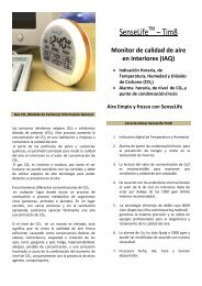
General mechanical overview6.1 ±0.15+0.732.2 -0.21.6 ±0.169.9 max2.97 ±0.1526.3 ±0.17.7 ±0.157.6 ±0.152.3 max13.2 ±0.22.549pins 110.7 ±0.219.6 ±0.13.18 ±0.1529.7 ±0.1Figure4a. Mechanical drawing <strong>SenseAir</strong> ® <strong>S8</strong> Article No 004-0-0050
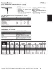
Figure 4b. Mechanical drawing <strong>SenseAir</strong> ® <strong>S8</strong> Article No 004-0-0051