bio-nano-machines for space applications - College of Engineering
bio-nano-machines for space applications - College of Engineering
bio-nano-machines for space applications - College of Engineering

You also want an ePaper? Increase the reach of your titles
YUMPU automatically turns print PDFs into web optimized ePapers that Google loves.
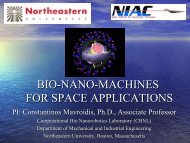
Phase II NIAC GrantFINAL REPORTBIO-NANO-MACHINES FOR SPACE APPLICATIONSSubmitted to:Dr. Robert A. Cassanova, DirectorNASA Institute <strong>for</strong> Advanced Concepts (NIAC)555A Fourteenth Street, N.W.Atlanta, Georgia 30318Tel: (404) 347-9633, FAX: (404) 347-9638Email: bcass@niac.usra.eduPrincipal Investigator:Constantinos Mavroidis, Ph.D., Pr<strong>of</strong>essorDepartment <strong>of</strong> Mechanical and Industrial <strong>Engineering</strong>Northeastern University, 375 Snell <strong>Engineering</strong> Center360 Huntington Avenue, Boston, MA 02115, USATEL: 617-373-4121, FAX: 617-373-2921EMAIL: mavro@coe.neu.edu, WEBPAGE: http://www.coe.neu.edu/~mavroJuly 23, 2006
List <strong>of</strong> ContributorsThe people who contributed towards the completion <strong>of</strong> the NIAC Phase II project arelisted below:a) Ajay Ummat – Is a PhD student in the Mechanical <strong>Engineering</strong> department atNortheastern University, Boston, MA. He is the main author <strong>of</strong> the NIAC reportsand contributed towards the design and conceptualization <strong>of</strong> <strong>space</strong> <strong>applications</strong>and the computational framework <strong>for</strong> designing <strong>bio</strong> <strong>nano</strong> <strong>machines</strong>.b) Pr<strong>of</strong>. Constantinos Mavroidis – Is a Pr<strong>of</strong>essor in the Department <strong>of</strong> Mechanicaland Industrial <strong>Engineering</strong>, Northeastern University, Boston. He is the PrincipalInvestigator <strong>for</strong> this project and the main contributor towards theconceptualization and design <strong>of</strong> the <strong>bio</strong> <strong>nano</strong> <strong>machines</strong> and the <strong>space</strong> <strong>applications</strong>.c) Pr<strong>of</strong>. Martin L.Yarmush – Is a Pr<strong>of</strong>essor <strong>of</strong> Surgery and Bioengineering,Harvard Medical School, Boston. He is the co-Principal Investigator <strong>for</strong> thisproject and his main contribution is towards the experimental activities <strong>for</strong> theproject, which includes protein characterization, mutations and its dynamics.d) Marianna Bei, D.M.D., D.M.Sc. – Is an Assistant Pr<strong>of</strong>essor <strong>of</strong> Dermatology,Harvard Medical School, Boston. She is a no cost consultant <strong>for</strong> this project andher expertise in <strong>bio</strong>logy helped us conceptualize the design <strong>of</strong> <strong>bio</strong> <strong>nano</strong> roboticsand its components.e) Gaurav Sharma – Is a PhD student in the Mechanical <strong>Engineering</strong> department atNortheastern University, Boston. His contribution was towards the design <strong>of</strong> a<strong>nano</strong>- hinge, a <strong>bio</strong> <strong>nano</strong> component which could be used <strong>for</strong> <strong>space</strong> <strong>applications</strong>.2
OverviewThis Phase II NIAC grant started on September 1, 2004. The project goals included:a) The identification and study (computationally and experimentally) <strong>of</strong> protein andDNA configurations that can be used as <strong>bio</strong>-<strong>nano</strong>-machine components.b) The design <strong>of</strong> two macro-scale devices <strong>for</strong> <strong>space</strong> application that will be using<strong>bio</strong>-<strong>nano</strong>-component assemblies. These devices are:b.1) The Networked TerraXplorer (NTXp) that is a long and light-weightnetwork <strong>of</strong> channels containing millions <strong>of</strong> <strong>bio</strong>-<strong>nano</strong>-robotic elements withultra-enhanced sensing and signaling capabilities <strong>for</strong> the detailed mappingand exploration <strong>of</strong> very large planetary surfaces.b.2) The All Terrain Astronaut Bio-Nano Gears (ATB) that will serve as anextra layer <strong>of</strong> shield on the astronaut providing early detection andprotection against dangerous and harmful environments or aiding in healingdamages caused to the astronaut.During the two year period <strong>for</strong> the project, the following research activities took placeand are described in detail in this report:4
List <strong>of</strong> Research Activities1. Establishment <strong>of</strong> the design requirements <strong>for</strong> the NTXp and the ATB due to the planetaryenvironmental conditions2. Identification and characterization <strong>of</strong> the <strong>bio</strong><strong>nano</strong> machine components <strong>for</strong> use in <strong>space</strong>3. Initiation <strong>of</strong> the system level design <strong>of</strong> NTXp4. Detailed description <strong>of</strong> the design and control principles <strong>of</strong> <strong>bio</strong><strong>nano</strong>robotic systems. Thischapter on <strong>bio</strong><strong>nano</strong>robotic systems was written to serve as our guideline <strong>for</strong> the designand control <strong>of</strong> all <strong>bio</strong><strong>nano</strong> components <strong>for</strong> the NTXp and the ATB and will be includedin the final report <strong>of</strong> this project.5. Identification and characterization <strong>of</strong> four <strong>bio</strong><strong>nano</strong> machine components <strong>for</strong> use in<strong>space</strong>.6. Sensor-signaling dynamics.7. Description <strong>of</strong> the computational framework <strong>for</strong> the optimization <strong>of</strong> the <strong>bio</strong> <strong>nano</strong>components.8. Setup <strong>of</strong> the computational studies on the effect <strong>of</strong> UV radiations <strong>of</strong> the <strong>bio</strong> <strong>nano</strong>components. Ab initio studies on small atomic systems and amino acids9. Effect <strong>of</strong> temperature on <strong>bio</strong>-<strong>nano</strong>-components.10. Effect <strong>of</strong> temperature on the atomic level.11. Nan<strong>of</strong>luidics actuator <strong>for</strong> NTXp transport mechanism.12. Design <strong>of</strong> ATB and radiation responsive molecular assembly <strong>for</strong> astronauts.13. Listing <strong>of</strong> future work and goals <strong>of</strong> this non invasive design <strong>for</strong> detecting <strong>space</strong>radiations.14. A brief overview <strong>of</strong> the world’s toughest bug which can sustain very high degree <strong>of</strong>radiations.5
5.2 System Level Design <strong>of</strong> NTXp .................................................................................. 1015.3 Deployment Scenario <strong>for</strong> NTXp............................................................................... 1025.4 Sensor – signal dynamics .......................................................................................... 1055.5 Micro-Nano fluidics actuator <strong>for</strong> NTXp transport mechanism ............................ 1075.5.1 Conceptual design <strong>for</strong> Micro-Nano fluidics Actuator........................................ 109Chapter 6: All Terrain Bio-<strong>nano</strong> (ATB) gears <strong>for</strong> Astronauts .............................................. 1136.1 Introduction ............................................................................................................... 1136.2 Space radiation & significance <strong>of</strong> its detection ....................................................... 1176.3 Health hazards from the <strong>space</strong> radiations............................................................... 1206.4 Design <strong>of</strong> All Terrain Bio-Nano suits: Architecture and Goals............................. 1216.4 The design <strong>of</strong> the “Layer – A”.................................................................................. 1226.5 Probabilistic molecular arrangement <strong>for</strong> optimized reaction initiation............... 1276.6 Inside reaction centers............................................................................................... 1296.7 Radiation resistant bacteria – Selecting the <strong>bio</strong><strong>nano</strong> components <strong>for</strong> ATB......... 141Chapter 7: Experimental Activities.......................................................................................... 1457.1 Introduction ............................................................................................................... 1457.2 Description <strong>of</strong> Research Area & Project Objectives .............................................. 1457.3 NMR analysis ............................................................................................................. 150Chapter 8: Future Activities ..................................................................................................... 152References.............................................................................................................................. 154Appendix – 1- RMSD <strong>of</strong> the individual residues inside the peptide ................................. 162Appendix – 2 - Quantum Monte Carlo implementation <strong>for</strong> hydrogen molecule ............ 167Appendix – 3 - Solving Schrodinger wave equation <strong>for</strong> H2 .............................................. 1728
Chapter 1: Bio<strong>nano</strong>robotics - A Field Inspired by Nature1.1 IntroductionThe underlying principle <strong>of</strong> <strong>bio</strong>mimetics deals with the understanding,conceptualization and mimicking nature’s way <strong>of</strong> handling various problems andsituations. Nature has inspired mankind <strong>for</strong> ages and has been a key source from whichwe can learn and adapt. Natural processes are extremely efficient in terms <strong>of</strong> energy andmaterial usage and provide us with many inspiring and thought provoking designs andprinciples. This chapter discusses <strong>bio</strong>mimetics at the <strong>nano</strong> scale, where we talk about<strong>nano</strong>robotics and its design principles which are inspired by nature’s way <strong>of</strong> doing thingsat that scale.Figure 1-1 describes the <strong>bio</strong>mimetics principle and details the various aspects <strong>of</strong>mimetics. It explains the mimetics at two levels when <strong>nano</strong> scale is considered. One is the“machine <strong>nano</strong> mimetics” principle meaning the creation <strong>of</strong> <strong>nano</strong>-machine componentsinspired by the equivalent machine components at the macro-scale and the other is the“<strong>bio</strong> <strong>nano</strong> mimetics” principle where <strong>bio</strong>logical entities such as proteins and DNA areused to create the <strong>nano</strong>-machine components. The field <strong>of</strong> <strong>nano</strong>robotics henceencapsulates these two mimetic principles, and inherits their various characteristics,design logic and advantages.Nanotechnology can best be defined as a description <strong>of</strong> activities at the level <strong>of</strong>atoms and molecules that have <strong>applications</strong> in the real world. A <strong>nano</strong>meter is a billionth<strong>of</strong> a meter, that is, about 1/80,000 <strong>of</strong> the diameter <strong>of</strong> a human hair, or 10 times thediameter <strong>of</strong> a hydrogen atom. The size-related challenge is the ability to measure,manipulate, and assemble matter with features on the scale <strong>of</strong> 1-100nm. In order to9
achieve cost-effectiveness in <strong>nano</strong>technology it will be necessary to automate molecularmanufacturing.Figure 1-1: Biomimetics – <strong>bio</strong> <strong>nano</strong>robotics, inspired by nature and machine.The engineering <strong>of</strong> molecular products needs to be carried out by robotic devices,which have been termed <strong>nano</strong>robots [Freitas, 1999, 2003]. A <strong>nano</strong>robot is essentially acontrollable machine at the <strong>nano</strong> meter or molecular scale that is composed <strong>of</strong> <strong>nano</strong>-scalecomponents and algorithmically responds to input <strong>for</strong>ces and in<strong>for</strong>mation. The field <strong>of</strong><strong>nano</strong>robotics studies the design, manufacturing, programming and control <strong>of</strong> the <strong>nano</strong>scalerobots.This review focuses on the state <strong>of</strong> the art in the emerging field <strong>of</strong> <strong>nano</strong>robotics andits <strong>applications</strong> and discusses in brief some <strong>of</strong> the essential properties and dynamical lawswhich make this field more challenging and unique than its macro scale counterpart. Thischapter is only reviewing <strong>nano</strong>-scale robotic devices and does not include studies related10
to <strong>nano</strong> precision tasks with macro robotic devices that usually are also included in thefield <strong>of</strong> <strong>nano</strong>-robotics (e.g. ATMs and other <strong>for</strong>ms <strong>of</strong> proximal probe microscopy).Nanorobots would constitute any active structure (<strong>nano</strong> scale) capable <strong>of</strong> actuation,sensing, signaling, in<strong>for</strong>mation processing, intelligence, and swarm behavior at <strong>nano</strong>scale. These functionalities could be illustrated individually or in combinations by a <strong>nano</strong>robot (swarm intelligence and co-operative behavior). So, there could be a whole genre <strong>of</strong>actuation and sensing or in<strong>for</strong>mation processing <strong>nano</strong> robots having ability to interact andinfluence matter at the <strong>nano</strong> scale. Some <strong>of</strong> the characteristic abilities that are desirable<strong>for</strong> a <strong>nano</strong>robot to function may include:i. Swarm Intelligence – decentralization and distributive intelligenceii. Self assembly and replication – assemblage at <strong>nano</strong> scale and ‘<strong>nano</strong> maintenance’iii. Nano In<strong>for</strong>mation processing and programmability – <strong>for</strong> programming andcontrolling <strong>nano</strong>robots (autonomous <strong>nano</strong>robots)iv. Nano to macro world interface architecture – an architecture enabling instantaccess to the <strong>nano</strong>robots and its control and maintenanceThere are many differences between macro and <strong>nano</strong>-scale robots. However, theyoccur mainly in the basic laws that govern their dynamics. Macro scaled robots areessentially in the Newtonian mechanics domain whereas the laws governing <strong>nano</strong>robotsare in the molecular quantum mechanics domain. Furthermore, uncertainty plays a crucialrole in <strong>nano</strong>robotic systems. The fundamental barrier <strong>for</strong> dealing with uncertainty at the<strong>nano</strong> scale is imposed by the quantum and the statistical mechanics and thermalexcitations. For a certain <strong>nano</strong> system at some particular temperature, there are positionaluncertainties that can not be modified or further reduced [Drexler, 1992].11
The <strong>nano</strong>robots are invisible to the naked eye, which makes them hard to manipulateand work with. Techniques like Scanning Electron Microscopy (SEM) and Atomic ForceMicroscopy (AFM) are being employed to establish a visual and haptic interface toenable us to sense the molecular structure <strong>of</strong> these <strong>nano</strong> scaled devices. Virtual Reality(VR) techniques are currently being explored in <strong>nano</strong>-science and <strong>bio</strong>-technologyresearch as a way to enhance the operator’s perception (vision and haptics) byapproaching more or less a state <strong>of</strong> ‘full immersion’ or ‘telepresence’. The development<strong>of</strong> <strong>nano</strong>robots or <strong>nano</strong> machine components presents difficult fabrication and controlchallenges. Such devices will operate in microenvironments whose physical propertiesdiffer from those encountered by conventional parts. Since these <strong>nano</strong> scale devices havenot yet been fabricated, evaluating possible designs and control algorithms requires usingtheoretical estimates and virtual interfaces/environments. Such interfaces/simulations canoperate at various levels <strong>of</strong> detail to trade-<strong>of</strong>f physical accuracy, computational cost,number <strong>of</strong> components and the time over which the simulation follows the <strong>nano</strong>-objectbehaviors. They can enable <strong>nano</strong>-scientists to extend their eyes and hands into the <strong>nano</strong>world,and they also enable new types <strong>of</strong> exploration and whole new classes <strong>of</strong>experiments in the <strong>bio</strong>logical and physical sciences. VR simulations can also be used todevelop virtual assemblies <strong>of</strong> <strong>nano</strong> and <strong>bio</strong>-<strong>nano</strong> components into mobile linkages and topredict their per<strong>for</strong>mance.Nanorobots with completely artificial components have not been realized yet. Theactive area <strong>of</strong> research in this field is focused more on molecular <strong>machines</strong>, which arethoroughly inspired by nature’s way <strong>of</strong> doing things at <strong>nano</strong> scale. Mother Nature has herown set <strong>of</strong> molecular <strong>machines</strong> that have been working <strong>for</strong> millions <strong>of</strong> years, and have12
een optimized <strong>for</strong> per<strong>for</strong>mance and design over the ages As our knowledge andunderstanding <strong>of</strong> these numerous <strong>machines</strong> continues to increase, we now see apossibility <strong>of</strong> using the natural <strong>machines</strong>, or creating synthetic ones from scratch, usingnature’s components. This chapter focuses more on molecular <strong>machines</strong> and exploresvarious designs and research prevalent in this field. The main goal in the field <strong>of</strong>molecular <strong>machines</strong> is to use various <strong>bio</strong>logical elements — whose function at thecellular level creates motion, <strong>for</strong>ce or a signal — as machine components. Thesecomponents per<strong>for</strong>m their preprogrammed <strong>bio</strong>logical function in response to the specificphysiochemical stimuli but in an artificial setting. In this way proteins and DNA couldact as motors, mechanical joints, transmission elements, or sensors. If all these differentcomponents were assembled together in the proper proportion and orientation they would<strong>for</strong>m <strong>nano</strong> devices with multiple degrees <strong>of</strong> freedom, able to apply <strong>for</strong>ces and manipulateobjects in the <strong>nano</strong>scale world. The advantage <strong>of</strong> using nature's machine components isthat they are highly efficient and reliable.Nanorobotics is a field which calls <strong>for</strong> collaborative ef<strong>for</strong>ts between physicists,chemists, <strong>bio</strong>logists, computer scientists, engineers and other specialists to work towardsthis common objective. Figure 1-2 details the various fields which come under the field<strong>of</strong> <strong>bio</strong> <strong>nano</strong>robotics (this is just a representative figure and not exhaustive in nature).Currently this field is still developing, but several substantial steps have been taken bygreat researchers all over the world who are contributing to this ever challenging andexciting field. The ability to manipulate matter at the <strong>nano</strong> scale is one core application<strong>for</strong> which <strong>nano</strong>robots could be the technological solution. A lot has been written in theliterature about the significance and motivation behind constructing a <strong>nano</strong>robot.13
Figure 1-2: Bio <strong>nano</strong>robotics – a truly multidisciplinary field.The <strong>applications</strong> range from medical to environmental sensing to <strong>space</strong> and military<strong>applications</strong>. Molecular construction <strong>of</strong> complex devices could be possible by <strong>nano</strong>robots<strong>of</strong> the future. From precise drug delivery to repairing cells and fighting tumor cells;<strong>nano</strong>robots are expected to revolutionize the medical industry in the future. These<strong>applications</strong> come under the field <strong>of</strong> <strong>nano</strong>medicine [Freitas, 1999, 2003] which is a veryactive area <strong>of</strong> research in <strong>nano</strong>technology. These molecular <strong>machines</strong> hence <strong>for</strong>m thebasic enablers <strong>of</strong> future <strong>applications</strong>.In the next section, we shall try to understand the principles, theory and utility <strong>of</strong> theknown molecular <strong>machines</strong> and look into the design and control issues <strong>for</strong> their creationand modification. A majority <strong>of</strong> natural molecular <strong>machines</strong> are protein-based whichinvolve using the exact replica <strong>of</strong> nature’s mechanism, while the DNA-based molecular<strong>machines</strong> use the basic properties <strong>of</strong> DNA to design various synthetic mechanisms(which might not be present in the nature). Nature deploys proteins to per<strong>for</strong>m various14
cellular tasks – from moving cargo to catalyzing reactions, while it has kept DNA as anin<strong>for</strong>mation carrier. It is hence understandable that most <strong>of</strong> the natural machinery is builtfrom proteins. With the powerful crystallographic techniques available in the modernworld, the protein structures are clearer than ever. The ever increasing computing powermakes it possible to dynamically model protein folding processes and predict thecon<strong>for</strong>mations and structure <strong>of</strong> lesser known proteins [Rohl et al, 2004]. All this helpsunravel the mysteries associated with the molecular machinery and paves the way <strong>for</strong> theproduction and application <strong>of</strong> these miniature <strong>machines</strong> in various fields includingmedicine, <strong>space</strong> exploration, electronics and military.1.2 Biomolecular Machines: Background and Significance1.2.1 SignificanceThe recent explosion <strong>of</strong> research in <strong>nano</strong>technology, combined with importantdiscoveries in molecular <strong>bio</strong>logy have created a new interest in <strong>bio</strong>molecular <strong>machines</strong>and robots. The main goal in the field <strong>of</strong> <strong>bio</strong>molecular <strong>machines</strong> is to use various<strong>bio</strong>logical elements — whose function at the cellular level creates motion, <strong>for</strong>ce or asignal, stores in<strong>for</strong>mation — as machine components. These components per<strong>for</strong>m theirpreprogrammed <strong>bio</strong>logical function in response to the specific physiochemical stimuli butin an artificial setting. In this way proteins and DNA could act as motors, mechanicaljoints, transmission elements, or sensors. If all these different components wereassembled together in the proper proportion and orientation they would <strong>for</strong>m <strong>nano</strong>deviceswith multiple degrees <strong>of</strong> freedom, able to apply <strong>for</strong>ces and manipulate objects in the<strong>nano</strong>scale world. The advantage <strong>of</strong> using nature's machine components is that they arehighly efficient [Kinosita et al.], and reliable. Just as conventional macro <strong>machines</strong> are15
used to generate <strong>for</strong>ces and motions to accomplish specific tasks, <strong>bio</strong> <strong>nano</strong><strong>machines</strong> canbe used to manipulate <strong>nano</strong>-objects, to assemble and fabricate other <strong>machines</strong> orproducts, to per<strong>for</strong>m maintenance, repair and inspection operations.Such <strong>bio</strong><strong>nano</strong>robotic devices will hopefully be part <strong>of</strong> the arsenal <strong>of</strong> future medicaldevices and instruments that will: 1) per<strong>for</strong>m operations, inspections and treatments <strong>of</strong>diseases inside the body, and 2) achieve ultra-high accuracy and localization in drugdelivery, thus minimizing side effects. Figure 1-3 shows an idealized rendition <strong>of</strong> a<strong>bio</strong>molecular <strong>nano</strong>robot repairing an infected cell in a blood vessel.Figure 1-3: A "<strong>nano</strong>robot" flowing inside a blood vessel, finds an infected cell. The <strong>nano</strong>robotattaches to the cell and projects a drug to repair or destroy the infected cell.The <strong>bio</strong><strong>nano</strong>robot will be able to attach to the infected cell alone, and deliver atherapeutic drug that can treat or destroy just the infected cell, sparing the surroundinghealthy cells. Development <strong>of</strong> robotic components composed <strong>of</strong> simple <strong>bio</strong>logicalmolecules is the first step in the development <strong>of</strong> future <strong>bio</strong>medical <strong>nano</strong>devices. Since theplanned complex systems and devices will be driven by these components, we must firstdevelop a detailed understanding <strong>of</strong> their operation. From the simple elements such as16
structural links to more advanced concepts as motors, each part must be carefully studiedand manipulated to understand its functions and limits.Figure 1-4 lists the most important components <strong>of</strong> a typical robotic system ormachine assembly and the equivalence between macro and potential <strong>bio</strong><strong>nano</strong>components.Beyond the initial component characterization is the assembly <strong>of</strong> the components intorobotic systems.Figure 1-4: Macro and Bio<strong>nano</strong> Equivalence <strong>of</strong> Robot Components17
Figure 1-5 shows one such concept <strong>of</strong> a <strong>nano</strong>-organism, with its ‘feet’ made <strong>of</strong>helical peptides and its body using carbon <strong>nano</strong>tubes while the power unit is a<strong>bio</strong>molecular motor. For this phase to be successful, a library <strong>of</strong> <strong>bio</strong>logical elements <strong>of</strong>every category must be available. At that point, conventional robotics can be used as aguide <strong>for</strong> fabrication <strong>of</strong> <strong>bio</strong><strong>nano</strong>robots that function in the same manner. There will besystems that have mobile characteristics to transport themselves, as well as other objects,to desired locations. Some <strong>bio</strong><strong>nano</strong>robots can be conceived as able to manufactureadditional elements and various structures. There may also be robots that not onlyper<strong>for</strong>m physical labor, but also sense the environment and react accordingly. There isno doubt that <strong>bio</strong>medical <strong>applications</strong> will be both a driving <strong>for</strong>ce and a beneficiary <strong>of</strong>these developments.Figure 1-5: The <strong>bio</strong>logical elements will be used to fabricate robotic systems. A vision <strong>of</strong> a <strong>nano</strong>organism:carbon <strong>nano</strong>tubes <strong>for</strong>m the main body; peptide limbs can be used <strong>for</strong> locomotion andobject manipulation, a <strong>bio</strong>molecular motor located at the head can propel the device in variousenvironments.18
1.2.2 Brief Review <strong>of</strong> Biomolecular MachinesWhile the majority <strong>of</strong> the prior research in this field has largely focused on<strong>bio</strong>molecular motors, several other <strong>nano</strong>-components such as sensors and evenassemblies <strong>of</strong> components in the <strong>for</strong>m <strong>of</strong> mechanisms have been studied. In themacroscopic world, what we understand by a ‘motor’ is a machine capable <strong>of</strong> impartingmotion associated by the conversion <strong>of</strong> energy. Biomolecular Motors have attracted a lot<strong>of</strong> attention recently because: 1) they operate at high efficiency, 2) some could be selfreplicatingand hence cheaper in mass usage, and 3) they are readily available in nature[Boyer, 1998]. A number <strong>of</strong> enzymes function as <strong>nano</strong>scale <strong>bio</strong>logical motors, such askinesin [Block, 1998; Schnitzer and Block, 1997], RNA polymerase [Wang et al, 1998],myosin [Kitamura et al 1999], and adenosine triphosphate (ATP) synthase function as<strong>nano</strong>scale <strong>bio</strong>logical motors [Montemagno and Bachand, 1999; Bachand andMontemagno, 2000; Soong et al, 2000; Noji et al, 1997; Yasuda et al, 1998; Walker,1998].1.2.2.1 The ATPase MotorOne <strong>of</strong> the most abundant rotary motors found in life <strong>for</strong>ms is F0F1 ATP synthase,commonly known as the “ATPase Motor”. Oxidative Phosphorylation was demonstratedover 50 years ago as an important process by which our bodies capture energy from thefood that we eat. The mechanism <strong>of</strong> this process was not known until 1997, when Boyerand Walker described the key role that ATP plays in the process [Boyer, 1998; Walker,1998]. Noji et al published the structural and per<strong>for</strong>mance data <strong>of</strong> the ATPase motor in1997 [Noji et al, 1997; Yasuda et al, 1998]. According to this study, the γ subunit, whichis about 1 nm in diameter, rotates inside the F1 subunit, which is about 5 nm in diameter,19
have implicated this myosin in the transport <strong>of</strong> a specific membrane compartment [Mehtaet al, 1999]. The role <strong>of</strong> ATP hydrolysis in kinesin motility has also been recentlydescribed [Farrell et al, 2002].1.2.2.3 The Flagella MotorsEscherichia coli and similar organisms are equipped with a set <strong>of</strong> rotary motors only45 nm in diameter. Each motor drives a long, thin, helical filament that extends severalcell body lengths out into the external medium. In addition to rotary engines andpropellers, E. coli’s standard accessories include particle counters, rate meters, andgearboxes, and thus have been described as a <strong>nano</strong>technologist’s dream [Berg, 2000].Berg developed one <strong>of</strong> the earliest models <strong>for</strong> the rotary motor [Berg, 1974]. Improvedmodels came in 1992 [Ueno et al, 1992; Ueno et al, 1994]. Flagella motor analysiscoupled to real-time computer assisted analysis <strong>of</strong> motion has also been per<strong>for</strong>med [Khanet al, 1998]. Researchers in Japan have applied crystallographic studies in order tounderstand the molecular structure <strong>of</strong> flagella motors as well as that <strong>of</strong> kinesin [Nambaand Vonderveczt, 1997]. Finally, Hess' group is attempting to build a <strong>nano</strong>scale trainsystem, complete with tracks, loading docks and a control system. Since motor proteinsare a thousand times smaller than any man-made motor, they aim to utilize them in asynthetic environment as engines powering the <strong>nano</strong>trains [Hess and Vogel, 2001].1.2.2.4 Other Motors and MechanismsIn addition to work on naturally existing motors, considerable ef<strong>for</strong>t is also beingapplied to develop synthetic molecular motors. The structure <strong>of</strong> the ATP synthase, a rodrotating inside a static wheel, suggests the use <strong>of</strong> rotaxanes as potential artificial models21
<strong>for</strong> natural motors [Harada, 2001]. Rotaxanes are organic compounds consisting <strong>of</strong> adumbbell-shaped component that incorporates one or more recognition sites in its rodsection and is terminated by bulky ‘stoppers’, encircled by one or more ring components.The possibility <strong>of</strong> manufacturing specific <strong>for</strong>ms <strong>of</strong> rotaxane and creating molecularmotors capable <strong>of</strong> guided rotary motion and the possibility <strong>of</strong> fueling such a motor bylight, electrons and chemical energy has been proposed [Schalley et al, 2001].Schemes <strong>for</strong> using pseudorotaxanes, rotaxanes and catenanes as molecular switchesto per<strong>for</strong>m chemical, electrochemical and photochemical switching, and controllablemolecular shuttles have also been proposed recently in the literature [Balzani et al, 1998].Molecular shuttles have been reported using α-cyclodextrin – a parent <strong>of</strong> rotaxanes andcatenanes [Harada, 2001]. A light-driven monodirectional rotor made <strong>of</strong> helical alkene,with rotation around a central carbon-carbon covalent bond due to chirality has beenreported [Koumura et al, 1999]. Another simple way to convert chemical energy intomechanical motion in a controlled fashion is by using a metal ion which can betranslocated reversibly between two organic compartments with the change <strong>of</strong> itsionization state, controllable by redox reaction or pH change [Amendola et al, 2001].Motility <strong>of</strong> unicellular organisms like vortecellids reminds us <strong>of</strong> energy storage andrelease by mechanical springs on a macromolecular scale. Spring-like action has beenobserved in sperm cells <strong>of</strong> certain marine invertebrates during fertilization. Springs andsupramolecular ratchets by actin polymerization have yet to be built in vitro, but theytheoretically can be generalized, as recently demonstrated [Mahadevan and Matsudaira,2000].22
1.2.2.5 DNA-Based Molecular Nano<strong>machines</strong>, Joints and ActuatorsSeveral researchers are exploring the use <strong>of</strong> DNA in <strong>nano</strong>scale mechanisms. DNA issmall, relatively simple and homogeneous, and its structure and function is wellunderstood. The predictable self-assembling nature <strong>of</strong> the double helix makes it anattractive candidate <strong>for</strong> engineered <strong>nano</strong>structures. This property has been exploited tobuild several complex geometric structures, including knots, cubes and various polyhedra[Seeman, 1998]. Mathematical analyses <strong>of</strong> the elastic structure <strong>of</strong> DNA using energyminimization methods have been per<strong>for</strong>med to examine its molecular stability, whereinshort DNA strands were treated as an elastic rod [Tobias et al, 2000]. Initial experimentson DNA visualization and manipulation using mechanical, electrical, and chemical meanshave been underway <strong>for</strong> a decade [Yuqiu et al, 1992; Hu et al, 2002]. A dynamic deviceproviding atomic displacements <strong>of</strong> 2-6 nm was proposed in [Mao et al, 1999], whereinthe chemically induced transition between the B and Z DNA morphologies acts as amoving <strong>nano</strong>scale device. A method <strong>for</strong> localized element-specific motion control wasseen in the reversible transition between four stranded topoisomeric DNA motifs (PX andJX2) thereby producing rotary motion [Yan et al, 2002]. A very important, though simpleDNA machine that resembles a pair <strong>of</strong> tweezers has been successfully created, whoseactuation (opening and closing) is also fueled by adding additional DNA fuel strands[Yurke et al, 2000].1.2.3 NanosensorsThe technology <strong>of</strong> <strong>nano</strong>sensing is also under development. For example, siliconprobes with single walled carbon <strong>nano</strong>tube tips are being developed[http://www.media.mit.edu/<strong>nano</strong>scale/].For sensing certain analytes, genetically23
engineered versions <strong>of</strong> pore-<strong>for</strong>ming proteins like Staphylococcus aureus alphahemolysinare also being studied [Kasianowicz and Bayley, 2003]. Ef<strong>for</strong>ts to detect<strong>bio</strong>logical warfare agents, like cholera toxins, by utilizing their ability to bind to a bilayermembrane in the presence <strong>of</strong> gangliosides are another example [Plant and Silin, 2003].Light sensors could be made using certain photoreceptive polypeptides containingazobenzene or spyropyran units as they respond to light or dark environmental conditionsby undergoing con<strong>for</strong>mational change, e.g. transition from random coil to a α-helix[Pieroni et al, 2001]. An optical DNA <strong>bio</strong>sensor plat<strong>for</strong>m has been reported using etchedoptical fiber bundles filled with oligonucleotide-functionalized microsphere probes[Ferguson et al, 1996]. Finally, work is in progress to develop sensors <strong>for</strong> brainimplantation, which would <strong>for</strong>etell the development <strong>of</strong> a stroke and be useful <strong>for</strong>perioperative on-line monitoring during coronary by-pass surgery [Manning and McNeil,2001].In addition to many <strong>of</strong> the examples mentioned above which generally correspond toone degree <strong>of</strong> freedom rotary actuators, there are many other machine elements, thefunctional capabilities <strong>of</strong> which have not yet been represented by <strong>bio</strong>molecular elements.In addition, the assembly <strong>of</strong> different molecules in a multi-degree <strong>of</strong> freedom machine orthe <strong>for</strong>mation <strong>of</strong> hybrid systems composed <strong>of</strong> <strong>bio</strong>molecules and synthetic non-organicelements has not yet been explored. In this context, our long term goal is to identify novel<strong>bio</strong>molecules that can be used as different types <strong>of</strong> machine components and to assemblethem into controlled multi-degree <strong>of</strong> freedom systems using organic and synthetic nonorganicparts.24
1.3 Design and Control Philosophies <strong>for</strong> Nanorobotic SystemsThe design <strong>of</strong> <strong>nano</strong>robotic systems requires the use <strong>of</strong> in<strong>for</strong>mation from a vast variety<strong>of</strong> sciences ranging from quantum molecular dynamics to kinematic analysis. In thischapter we assume that the components <strong>of</strong> a <strong>nano</strong>robot are made <strong>of</strong> <strong>bio</strong>logicalcomponents, such as proteins and DNA strings. So far, there is no particular guideline ora prescribed manner that details the methodology <strong>of</strong> designing a <strong>bio</strong>-<strong>nano</strong>robot. There aremany complexities that are associated with using <strong>bio</strong> components (such as protein foldingand presence <strong>of</strong> aqueous medium), but the advantages <strong>of</strong> using these are also quiteconsiderable. These <strong>bio</strong> components <strong>of</strong>fer immense variety and functionality at a scalewhere creating a man made material with such capabilities would be extremely difficult.These <strong>bio</strong> components have been perfected by nature through millions <strong>of</strong> years <strong>of</strong>evolution and hence these are very accurate and efficient. As noted in the review sectionon Molecular Machines, F 1 -ATPase is known to work at efficiencies which are close to100%. Such efficiencies, variety and <strong>for</strong>m are not existent in any other <strong>for</strong>m <strong>of</strong> materialfound today. Another significant advantage in protein-based <strong>bio</strong> <strong>nano</strong> components is thedevelopment and refinement over the last 30 years <strong>of</strong> tools and techniques enablingresearchers to mutate proteins in almost any way imaginable. These mutations canconsist <strong>of</strong> anything from simple amino acid side-chain swapping, amino acid insertions ordeletions, incorporation <strong>of</strong> non-natural amino acids, and even the combination <strong>of</strong>unrelated peptide domains into whole new structures. An excellent example <strong>of</strong> thisapproach is the use <strong>of</strong> zinc to control F 1 -ATPase, which is able to rotate a <strong>nano</strong>propellerin the presence <strong>of</strong> ATP. A computational algorithm [Hellinga and Richards, 1991] wasused to determine the mutations necessary to engineer an allosteric zinc-binding site into25
the F 1 -ATPase using site-directed mutagenesis. The mutant F 1 -ATPase would rotate anactin filament in the presence <strong>of</strong> ATP with average torque <strong>of</strong> 34 pN nm. This rotationcould be stopped with the addition <strong>of</strong> zinc, and restored with the addition <strong>of</strong> a chelator toremove the zinc from the allosteric binding site [Liu et al, 2002]. This type <strong>of</strong> approachcan be used <strong>for</strong> the improvement <strong>of</strong> other protein-based <strong>nano</strong>components. These <strong>bio</strong>components seem to be a very logical choice <strong>for</strong> designing <strong>nano</strong>robots. In addition sincesome <strong>of</strong> the core <strong>applications</strong> <strong>of</strong> <strong>nano</strong>robots are in the medical field, using <strong>bio</strong>components<strong>for</strong> these <strong>applications</strong> seems to be a good choice as they both <strong>of</strong>fer efficiencyand variety <strong>of</strong> functionality. This idea is clearly inspired by nature’s construction <strong>of</strong>complex organisms such as, bacteria and viruses which are capable <strong>of</strong> movement, sensingand organized control. Hence our scope would be limited to the usage <strong>of</strong> these <strong>bio</strong>components in the construction <strong>of</strong> <strong>bio</strong>-<strong>nano</strong>robotics. A roadmap is proposed which detailsthe main steps towards the design and development <strong>of</strong> <strong>bio</strong>-<strong>nano</strong>robots.1.3.1 The RoadmapThe roadmap <strong>for</strong> the development <strong>of</strong> <strong>bio</strong>-<strong>nano</strong>robotic systems <strong>for</strong> future <strong>applications</strong>(medical, <strong>space</strong> and military) is shown in Figure 1-6. The roadmap progresses throughthe following main steps:Step 1: Bio Nano ComponentsDevelopment <strong>of</strong> <strong>bio</strong>-<strong>nano</strong> components from <strong>bio</strong>logical systems is the first step towardsthe design and development <strong>of</strong> an advanced <strong>bio</strong>-<strong>nano</strong>robot, which could be used <strong>for</strong>future <strong>applications</strong> (see Figure 1-7). Since the planned systems and devices will becomposed <strong>of</strong> these components, we must have a sound understanding <strong>of</strong> how thesebehave and how they could be controlled. From the simple elements such as structural26
links to more advanced concepts such as motors, each component must be carefullystudied and possibly manipulated to understand the functional limits <strong>of</strong> each one <strong>of</strong> them.DNA and carbon <strong>nano</strong>tubes are being fabricated into various shapes, enablingpossibilities <strong>of</strong> constructing newer and complex devices.Figure 1-6: The Roadmap, illustrating the system capability targeted as the project progresses.These <strong>nano</strong>-structures are potential candidates <strong>for</strong> integrating and housing the <strong>bio</strong><strong>nano</strong>components within them. Proteins such as rhodopsin and bacteriorhodopsin are afew examples <strong>of</strong> such <strong>bio</strong>-<strong>nano</strong> components. Both these proteins are naturally found in<strong>bio</strong>logical systems as light sensors. They can essentially be used as solar collectors togather abundant energy from the sun. This energy could either be harvested (in terms <strong>of</strong>proton motive <strong>for</strong>ce) <strong>for</strong> later use or could be consumed immediately by othercomponents, such as the ATP Synthase <strong>nano</strong> rotary motor. The initial work is intended to27
transport themselves as well as other objects to desired locations at <strong>nano</strong> scale.Furthermore, some <strong>bio</strong>-<strong>nano</strong>robots need to assemble various <strong>bio</strong>-components and <strong>nano</strong>structures,including in situ fabrication sites and storage areas others will manipulateexisting structures and maintain them. There will also be robots that not only per<strong>for</strong>mphysical labor, but also sense the environment and react accordingly. There will besystems that will sense an oxygen deprivation and stimulate other components to generateoxygen, creating an environment with stable homoeostasis.Figure 1-8 (Step 2): Modular Organization concept <strong>for</strong> the <strong>bio</strong>-<strong>nano</strong> robots. Spatialarrangements <strong>of</strong> the various modules <strong>of</strong> the robots are shown. A single <strong>bio</strong> <strong>nano</strong> robot will haveactuation, sensory and in<strong>for</strong>mation processing capabilities.Step 3: Distributive Intelligence, Programming and ControlWith the individual <strong>bio</strong>-<strong>nano</strong>robots capable <strong>of</strong> basic functions, we would now need todevelop concepts that would enable them to collaborate with one another to develop“colonies” <strong>of</strong> similar <strong>nano</strong>robots. This design step could lay the foundation towards the29
concept <strong>of</strong> <strong>bio</strong>-<strong>nano</strong> swarms (distributive <strong>bio</strong>-<strong>nano</strong>robots) (see Figure 1-9A). Here workhas to be done towards the control and programming <strong>of</strong> such swarms. This will evolveconcepts like distributive intelligence in the context <strong>of</strong> <strong>bio</strong> <strong>nano</strong>robots. Designing swarms<strong>of</strong> <strong>bio</strong>-<strong>nano</strong> robots capable <strong>of</strong> carrying out complex tasks and capable <strong>of</strong> computing andcollaborating amongst them will be the focus <strong>of</strong> this step. There<strong>for</strong>e, the basiccomputational architectures needs to be developed and rules need to be evolved <strong>for</strong> the<strong>bio</strong><strong>nano</strong>robots to make intended decisions at the <strong>nano</strong> scale.ABFigure 1-9 (Step 3): (A) Basic <strong>bio</strong> <strong>nano</strong> robot <strong>for</strong>ming a small swarm <strong>of</strong> five robots. The spatialarrangement <strong>of</strong> the individual <strong>bio</strong> <strong>nano</strong> robot will define the arrangement <strong>of</strong> the swarm. Theseswarms could be re-programmed to <strong>for</strong>m bindings with various other types <strong>of</strong> robots. The number<strong>of</strong> robots making a swarm will be determined by the mission. Such swarms will attach additional<strong>bio</strong><strong>nano</strong>robots at run time and replace any non functional ones. (B) A basic <strong>bio</strong>-<strong>nano</strong>computational cell. This will be based on one <strong>of</strong> the properties <strong>of</strong> the <strong>bio</strong> molecules, which is“reversibility”.To establish an interface with the macro world, the computers and electronic hardwarehave to be designed as well. Figure 1-10 shows the overall electronic communicationarchitecture. Humans should be able to control and monitor the behavior and action <strong>of</strong>these swarms. This means that basic computational capabilities <strong>of</strong> the swarms will need30
to be developed. A representative computational <strong>bio</strong>-<strong>nano</strong> cell, which will be deployedwithin a <strong>bio</strong>-<strong>nano</strong>-robot, is shown in Figure 1-9B. This basic computational cell willinitially be designed <strong>for</strong> data retrieval and storage at the <strong>nano</strong> scale. This capability willenable us to program (within certain degrees <strong>of</strong> freedom) the swarm behavior in the <strong>bio</strong><strong>nano</strong>robots. We will further be able to get their sensory data (from <strong>nano</strong> world) back tothe macro world through these storage devices. This programming capability wouldcontrol the <strong>bio</strong>-<strong>nano</strong> robotics system and hence is very important.Step 4: Automatic Fabrication and In<strong>for</strong>mation Processing MachinesSpecialized <strong>bio</strong>-<strong>nano</strong>robotic swarms would need to be designed to carry out complexmissions, such as sensing, signaling and data storage. The next step in <strong>nano</strong>roboticdesigning would see the emergence <strong>of</strong> automatic fabrication methodologies (see Figure1-11, which only shows the floor concept <strong>of</strong> assembling <strong>bio</strong><strong>nano</strong>robots) <strong>of</strong> such <strong>bio</strong>-<strong>nano</strong>robots in vivo and in vitro. Capability <strong>of</strong> in<strong>for</strong>mation processing will be a keyconsideration <strong>of</strong> this step. This would enable <strong>bio</strong>-swarms to have capability <strong>of</strong> adjustingbased on their interacting environment they will be subjected to. These swarms could beprogrammed <strong>for</strong> more than one energy source and hence would have an ability to per<strong>for</strong>min an alternate environment. Energy management, self-repairing, and evolving will besome <strong>of</strong> the characteristics <strong>of</strong> these swarms.1.3.2 Design Architecture <strong>for</strong> the Bio-Nanorobotic Systemsa) Modular Organization: Modular organization defines the fundamental rule andhierarchy <strong>for</strong> constructing a <strong>bio</strong>-<strong>nano</strong>robotic system. Such construction is per<strong>for</strong>medthrough stable integration (energetically in the most stable state) <strong>of</strong> the individual ‘<strong>bio</strong>modulesor components’, which constitute the <strong>bio</strong>-<strong>nano</strong>robot. For example, if the entity31
ABCD, defines a <strong>bio</strong>-<strong>nano</strong>robot having some functional specificity (as per the CapabilityMatrix defined in Table 1) then, A, B, C, and D are said to be the basic <strong>bio</strong>-modulesdefining it.Bio-<strong>nano</strong>ComputationalCell 1Nano manmade devicesMicroDevicesPowerSourceBio-<strong>nano</strong>ComputationalCell 2Nano manmade devicesMacro WorldBio-<strong>nano</strong>ComputationalCell iNano manmade devicesMicroDevicesSelf assembly, Sensing,and trigger mechanismAmplificationmechanismsMacro actuators orcommunication devicesFigure 1-10: Feedback path from <strong>nano</strong> to macro world route.Figure 1-11 (Step 4): An automatic fabrication floor layout. Different color represents differentfunctions in automatic fabrication mechanisms. The arrows indicate the flow <strong>of</strong> components onthe floor layout. Section 1 Basic stimuli storage – Control expression; Section 2 Biomolecular component manufacturing (actuator / sensor); Section 3 Linking <strong>of</strong> <strong>bio</strong>-<strong>nano</strong>components; Section 4 Fabrication <strong>of</strong> <strong>bio</strong>-<strong>nano</strong> robots (assemblage <strong>of</strong> linked <strong>bio</strong>-<strong>nano</strong>components).32
Table 1: Defining the Capability Matrix <strong>for</strong> the Bio-ModulesThe basic construction will be based on the techniques <strong>of</strong> molecular modeling withemphasis on principles such as Energy Minimization on the hyper surfaces <strong>of</strong> the <strong>bio</strong>modules;Hybrid Quantum-Mechanical and Molecular Mechanical methods; EmpiricalForce field methods; and Maximum Entropy Production in least time. Modularorganization also enables the <strong>bio</strong>-<strong>nano</strong>robots with capabilities such as, organizing into33
swarms, a feature, which is extremely desirable <strong>for</strong> various <strong>applications</strong>. Figures 1-12A& B show the conceptual representation <strong>of</strong> Modular Organization. Figure 1-12C shows amore realistic scenario in which all the modules are defined in some particular spatialarrangements based on their functionality and structure. A particular module couldconsist <strong>of</strong> other group <strong>of</strong> modules, or sub modules.Figure 1-12: (A) A Bio-Nano-Robotic Entity ‘ABCD’, where A, B, C and D are the various BioModules constituting the <strong>bio</strong>-<strong>nano</strong>-robot. In our case these <strong>bio</strong> modules will be set <strong>of</strong> stableconfigurations <strong>of</strong> various proteins and DNAs. (B) A Bio-Nano-Robot (representative), as a result<strong>of</strong> the concept <strong>of</strong> Modular Organization. All the modules will be integrated in such a way so as topreserve the basic behavior (<strong>of</strong> self-assembly and self organization) <strong>of</strong> the <strong>bio</strong>-components at allthe hierarchies. The number <strong>of</strong> modules employed is not limited to four or any number. It’s afunction <strong>of</strong> the various capabilities required <strong>for</strong> a particular mission. (C) A molecularrepresentation <strong>of</strong> the figure in part B. It shows the red core and green and blue sensory andactuation <strong>bio</strong>-modules.34
c) In<strong>for</strong>mation Processing – Memory Storage and Programming: Capability <strong>of</strong>in<strong>for</strong>mation processing is one <strong>of</strong> the most novel features <strong>of</strong> the proposed <strong>bio</strong>-<strong>nano</strong>system. Here we underline some design aspects on memory storage mechanisms and <strong>bio</strong><strong>nano</strong>intelligence. The main hypotheses considered <strong>for</strong> designing such a mechanism are:i) reversibility <strong>of</strong> the <strong>bio</strong>-chemical reactions and molecules, and ii) Functions arises fromcon<strong>for</strong>mations. The basic storage and retrieval mechanism is represented in figure 1-15below.Figure 1-15: Showing the Bio Nano Code and the Fractal Modularity Principle. The dotted linerepresents the “reversibility” <strong>of</strong> the <strong>bio</strong>-chemical reaction.A “Parent Cell” contains two stable structure <strong>of</strong> DNAs (DNA 1 and DNA 2) whichbind within themselves four trigger ions or similar <strong>bio</strong>-molecule (Trigger A, Trigger B,Trigger C and Trigger D). These specific numbers <strong>of</strong> <strong>bio</strong>-components are used only <strong>for</strong>illustration purposes, exact number would vary upon the required <strong>bio</strong>-chemical reactions.Additional four different ions (Ion A, Ion B, Ion C & Ion D) are defined, which wouldreact with the stable con<strong>for</strong>mations <strong>of</strong> the two DNAs in the parent cell. The workingprinciple is illustrated in the following equations (these equations are representative <strong>of</strong>the plausible <strong>bio</strong>-chemical reactions):37
Presence<strong>of</strong> a Field Gradient1 1 ←⎯⎯⎯⎯⎯⎯⎯⎯⎯⎯⎯⎯⎯⎯⎯⎯→fully reversible reaction1+IonA + ( DNA + DNA ) ( DNA ) + Trga b *APresence<strong>of</strong> a Field Gradient1 1 ←⎯⎯⎯⎯⎯⎯⎯⎯⎯⎯⎯⎯⎯⎯⎯⎯→fully reversible reaction1+IonB + ( DNA + DNA ) ( DNA ) + Trga b **BIonC+Presence<strong>of</strong> a Field Gradient+ ( DNA + DNA ) ←⎯⎯⎯⎯⎯⎯⎯⎯⎯⎯⎯⎯⎯⎯⎯⎯→ ( DNA * ) + Trg2a 2b fully reversible reaction2CPresence<strong>of</strong> a Field Gradient2 2 ←⎯⎯⎯⎯⎯⎯⎯⎯⎯⎯⎯⎯⎯⎯⎯⎯→fully reversible reaction2+IonD + ( DNA + DNA ) ( DNA ) + Trga b **D___________________________________________________________4 Ions ( Input ReactsWithGenerates) ←⎯⎯⎯⎯ ⎯⎯⎯⎯→ Bio _ Chemical _ Center ←⎯⎯⎯⎯ ⎯⎯⎯⎯→ 4 TriggersGeneratesReactsWith+ + +Where, the four basic ions are represented by: IonA ; IonB ; IonC ; IonD+ and theDNAs are represented by the following two symbols (<strong>for</strong> j = 1, 2); DNAja;DNA jb .The ‘a’& ‘b’ sub script represents one <strong>of</strong> the chains <strong>of</strong> the double helix <strong>of</strong> the DNA.The trigger ions are designed to bind with the child DNAs so as to change theircon<strong>for</strong>mations. When these trigger ions are released, altered con<strong>for</strong>mations <strong>of</strong> the DNAsare left in the parent cell. These new con<strong>for</strong>mations should also be stable at those ionicconcentrations and field gradients. These released trigger ions flows into the adjacent“memory child” cells thereby changing the con<strong>for</strong>mation their DNAs.Hence, this change in con<strong>for</strong>mation <strong>of</strong> the DNAs <strong>of</strong> the child cell along with theparent cell DNAs constitutes the data storage (and retrieval) mechanism (as shown infigure 1-16). Four Memory child cells are defined in accordance with the possiblenumber <strong>of</strong> trigger ions generated as a result <strong>of</strong> the <strong>bio</strong>chemical reactions in the ParentCell DNAs. This change in con<strong>for</strong>mation will act as the memory storage mechanism <strong>for</strong>38
us. This change in the con<strong>for</strong>mation <strong>of</strong> the DNAs has to be long-term and stable and atthe same time reversible under the application <strong>of</strong> specific conditions (ions, temperature,pressure and pH value <strong>of</strong> the environment).While storing the data, the ions (A, B, C & D) are passed through the ion channelsconnected with the parent cell. Retrieval <strong>of</strong> the data is the reversible process where thetrigger ions are flowed through the ion channels <strong>of</strong> the memory child cells towards theparent cell (Mechanism shown in figure 1-17). Hence a reversible mechanism isestablished between the Parent Cell and the Memory child cells. Hence, this efficientin<strong>for</strong>mation storage device could be used to program the behavior <strong>of</strong> the <strong>bio</strong>-<strong>nano</strong> systemwhich will embed this in its “inner core” module.Figure 1-16: Basic In<strong>for</strong>mation Processing Bio Nano Cell39
ehavior and Ion Concentration could be related to the intensity <strong>of</strong> the behavior <strong>of</strong> a<strong>bio</strong>-<strong>nano</strong> robotic system.1.4 Self Replication – mimetics a novel property <strong>of</strong> living systems1.4.1 SignificanceMimetics <strong>of</strong> self replication, as exhibited by nature, would influence any <strong>nano</strong> levelapplication. We would need an army <strong>of</strong> <strong>nano</strong>robots (or living systems), mass-producedvia techniques <strong>of</strong> self-replication (or life), to carry out many meaningful tasks at the <strong>nano</strong>scale. These <strong>applications</strong> involving <strong>nano</strong>robots demand that these <strong>machines</strong> aremanufactured in millions or billions and in a time frame reasonable <strong>for</strong> a particularapplication. One <strong>of</strong> nature’s noblest properties is that <strong>of</strong> life. It is how nature progressesthrough its environment ever adapting and evolving. Though philosophically, what lifemeans and what constitutes it is not very clear, but what’s clear is how nature propagatesitself with time and survives, every day and every moment! This is one attribute <strong>of</strong> naturewhich is <strong>of</strong> prime importance to us, as researchers <strong>of</strong> science and engineering, and which,if understood, would bring a unique revolution, which in a way would change the course<strong>of</strong> our lives.The concept <strong>of</strong> self-replicating mechanisms (SRM) or mimetics <strong>of</strong> life is not new[Freitas and Merkle, 2004]. We are perfect examples <strong>of</strong> these kinds <strong>of</strong> systems. We arewounded and our internal mechanisms heal it, with some differences in some cases.Taking the example <strong>of</strong> the wound and its healing process, we move ahead and try andanalyze how we can achieve such behaviors in the mechanisms, which we design. Core tothe concept <strong>of</strong> self-replication lays the basic material (DNA/RNA) which undergoes suchactivity. For the current scenario, we hardly know why these materials behave in thisfashion, but what we know is how they behave and this creates the stepping stone <strong>for</strong> us42
to move ahead in our quest. Be<strong>for</strong>e getting into some <strong>of</strong> the possible designs, a briefdiscussion on the application <strong>of</strong> such mechanisms is necessary. Why after all we needliving systems or self-replications? Where they would be best suited?1.4.2 Applicationsa) Consider that your application depends upon a particular part, a mechanical, anelectrical or any other physical, <strong>bio</strong>logical or chemical element. And in the process, someelement fails, or starts developing problems. We will need some self-rectifyingmechanisms within our application to detect such changes and rectify them. It’s similar toour wound example. We can think <strong>of</strong> many <strong>applications</strong> where we would desire suchbehavior. Given some initial material feedstock it would be desired that the selfreplicatingmechanisms would rectify the problems. Having said that we can classify theself-replicating mechanisms in the order we classify our main mechanisms or <strong>machines</strong>.• Mechanical self-replicating mechanisms.• Electrical self-replicating mechanisms.• Chemical or <strong>bio</strong>logical self-replicating mechanisms.There could be several other classifications, which would depend upon the way<strong>applications</strong> are classified. Numerous other examples <strong>of</strong> the <strong>applications</strong>, which couldfollow the lines <strong>of</strong> our wound example, could be thought <strong>of</strong>. It just depends upon theextent <strong>of</strong> our imaginations. For example, suppose that we build some SRM which mimicsthe living system and its function is to detect a crucial defect in a mechanical element andwhen detected mend that defect. So if we are able to device such mechanisms, it couldsignificantly enhance the lives and per<strong>for</strong>mance <strong>of</strong> the system. The system in thisexample would be designed and constructed to work at <strong>nano</strong> scale, and there<strong>for</strong>e they43
would have an ability to detect very slight defects and would start working towardsrectifying it.b) Remote Applications would also benefit from SRM systems. Maintaining these<strong>applications</strong> requires a constant human interaction. If these systems mimic livingsystem’s coded logic and goals then it would be able to per<strong>for</strong>m optimally with minimalhuman interventions. For example, deep <strong>space</strong> explorations would require circuits,<strong>machines</strong>, equipments to adjust and adapt with time and as per the conditions they wouldbe subjected to.c) Applications at the <strong>nano</strong> scale. This category <strong>of</strong> <strong>applications</strong> would be mostinfluenced by our <strong>bio</strong> mimetic systems because they could lay the foundations <strong>of</strong> <strong>nano</strong>devices that have the capability <strong>of</strong> manipulating molecular matter.In the following section we would attempt to define some <strong>of</strong> the guidelines andworking philosophies <strong>for</strong> designing and fabricating such replicating systems. The detailsare the thoughts and ideas <strong>of</strong> the authors and are not verified or supported byexperimental facts.1.4.3 The Design <strong>of</strong> Life Mimetic SystemsThe design <strong>of</strong> life mimetic systems requires new innovative materials to be designedthat behave in the same fashion as the one designed by nature. These new materials aretermed as “intrinsic materials” from here on.1.4.3.1 Intrinsic MaterialUnique arrangements <strong>of</strong> the constituent atoms <strong>of</strong> intrinsic materials would give rise to:• unique potential field surface around them• unique charge distribution44
• unique internal energy gradientsIt is through these internal energy gradients that two particular intrinsic materialswould interact with each other. Hence the behavior <strong>of</strong> the intrinsic material would be adirect function <strong>of</strong> its internal energy gradients.1.4.3.2 Interaction LawsThe final objective <strong>of</strong> any two interacting intrinsic materials would be to achieve theinherent balance <strong>of</strong> the resulting system (termed as self-balancing). This would translateto achieving minimum energy gradients in all the directions <strong>for</strong> all the interactingmaterials subjected to external potentials and stochastic environment. The final systemwould then be defined by its new achieved internal energy gradients and other inherentdistributions. These intrinsic energy gradients would also be constantly influenced orvaried by the external fields and potentials. The true statistical nature <strong>of</strong> these variationsis one <strong>of</strong> the important factors to study and understand intrinsic materials.1.4.3.3 Self-BalancingIt implies that the materials considered would tend to align with their intrinsic energygradients and would try to minimize the instantaneous imbalance. The classical instance<strong>of</strong> self-replication via energy-minimized self-assembly was first demonstrated in the late1950s. The canonical example <strong>of</strong> this approach is called the Penrose Blocks (Penrose,1957, 1958). The unbalance and the property <strong>of</strong> self-balancing are similar in essence towhat is postulated by the law <strong>of</strong> entropy. This concept <strong>of</strong> self-balancing is motivatedfrom the law <strong>of</strong> maximum entropy production, which says that a system follows a pathwhich minimizes the potential or maximizes entropy at the maximum rate [Archives <strong>of</strong>Science, 2001].45
1.4.3.4 Growth and its Growth LimitAn intrinsic material needs to possess property <strong>of</strong> growth (an important variable <strong>for</strong>replication). This property <strong>of</strong> growth only occurs when the system is provided with someenergy maybe in the <strong>for</strong>m <strong>of</strong> additional intrinsic material or external potential gradients.Growth cannot happen in isolation. This implies that in the process <strong>of</strong> self-balancing, it ispossible that the particular configuration <strong>of</strong> the intrinsic material is stable up to aparticular level. This level would be governed by the strength <strong>of</strong> the intrinsic potentialgradients <strong>for</strong> that intrinsic material and the extrinsic fields. There<strong>for</strong>e, growth implies thatthe intrinsic material can alter its internal distribution <strong>of</strong> atoms without disturbing its selfbalanceor creating energetically unfavorable intrinsic potentials or dynamics. But thisgrowth can only be achieved to a particular extent, beyond which the system tends todivide by following the paths which might be defined by the laws <strong>of</strong> maximum entropyproduction and free energy minimizations. And this particular limit <strong>of</strong> growth is termedas Reproductive Limit. Tracking such paths by carrying out quantum evolution at asystem level could be one <strong>of</strong> the challenges <strong>of</strong> this field and might hold potential toexplain such behavior.1.4.3.5 Self-Filtering and Self HealingThe concept <strong>of</strong> replication further demands that the materials thus designed shouldexhibit the property <strong>of</strong> self-filtering and self-healing. Self-filtering implies that thematerial involved in the systems exhibiting self replication will not allow any kind <strong>of</strong>growth pattern but only a particular one. This particular growth pattern (which inherentlydepends on the interactions <strong>of</strong> the components) will determine which material it binds to46
and to which it doesn’t. Hence such systems will only interact with certain intrinsicmaterials.In the process <strong>of</strong> this growth, a readjustment <strong>of</strong> the intrinsic material occurs. As theaddition <strong>of</strong> further intrinsic material takes place, the whole system tries to align itselftowards the most dynamical stable state subject to certain laws, which are not totallyunderstood (energy minimization, maximized entropy). This adjustment goes on with theself-filtering process. If at any incremental stage system doesn’t find the kind and type <strong>of</strong>material it is adaptable <strong>for</strong>, it wouldn’t bind and probably in due time reject that particularmaterial and in the end wouldn’t have any growth. By rejection, it might imply that eitherthe system doesn’t align or bind with the material or marks it as an unstable configurationand seeks <strong>for</strong> the opportunity to replace it immediately. Hence it acts as a self-healer.1.4.4 Self Replication – A GedankenexperimentLet us try to replicate a system, based on the properties described above. Consider asystem A, consisting <strong>of</strong> some intrinsic materials (Figure 1-19). The system A iscompletely defined by the way these intrinsic materials are associated and aligned withinit. According to the above properties <strong>of</strong> self-replicating mechanisms, it is observed that,the intrinsic materials <strong>of</strong> the system could be broken down into further fundamentalintrinsic materials.Any stable configuration <strong>of</strong> the individual intrinsic material is in sync with theproperty <strong>of</strong> self-balancing. Now when a particular intrinsic material (say 1) gets in aninteractive distance <strong>of</strong> another intrinsic material (say 2), then these two intrinsic materialstry to <strong>for</strong>m another subsystem A1 within the super system A, following the property <strong>of</strong>self balancing. These two intrinsic materials combined will have some other function <strong>of</strong>47
intrinsic energy gradient and could be the sum <strong>of</strong> the individual intrinsic energy gradients<strong>of</strong> the intrinsic materials and the applied external fields.Now this argument could be extended to the situation when the third intrinsic material(say 3) comes into the picture. This intrinsic material 3 would not only interact withintrinsic material 1 but also with intrinsic material 2. Finally, a system A comes intogeneration, because <strong>of</strong> self-balancing acts <strong>of</strong> these three intrinsic materials. Theconfiguration they achieve becomes highly stable <strong>for</strong> that particular situation. Now let’sintroduce more energy to the system A. It would be in the <strong>for</strong>m <strong>of</strong> introducing intrinsicmaterials or applying external gradients to the system A or both. Figure 1-20 explains theconcept.Figure 1-19: System <strong>of</strong> intrinsic materials – a Self replicative system A.Here because <strong>of</strong> the process <strong>of</strong> self-filtering, copies <strong>of</strong> intrinsic material 1, 2 and 3 areintroduced. The property <strong>of</strong> self-balancing comes into dominance and the systems tries toadjust itself into the most stable state. As defined earlier, the initial state is the most stable48
state; following is what happens to the system A. Two sub systems within the mainsystems are made as shown in Figure 1-21.External GradientsFigure 1-20: Energy being added to the self replicative system A in the <strong>for</strong>m <strong>of</strong> newer intrinsicmaterial (1, 2 and 3) and external gradient (this external gradient is applied either to aid theinteraction between the intrinsic materials or to impart a particular dynamics to the system <strong>for</strong>favorable environment <strong>for</strong> the interaction).The alignment <strong>of</strong> subsystems A1 and A2 is similar to the one <strong>of</strong> the initial system, thatis, A. Please note that such system is possible, because we can control the externalparameters, namely, extrinsic gradients and the intrinsic material introduced. Thetriangles drawn in the figure above shows the configuration <strong>of</strong> the intrinsic materials <strong>of</strong>subsystems A1 and A2. The dotted lines, depict the interaction between the old intrinsicmaterials and the new ones and the possible configuration that could be achieved.Now because the external gradients are still applicable a unique instability in thesystem occurs. The system tries to self-balance and in the process leads to its most stableconfigurations, which was its initial one (the initial configuration, system A). Figure 1-22explains the concept. In the end, the original system A replicates into system B and system49
C. Both these new systems, have the same functionalities as defined by the originalsystem (A), because the have received the same configuration and the same intrinsicmaterials.Figure 1-21: Creation <strong>of</strong> stable subsystems within the original system A (which as a whole ismarginally unstable under the external gradients and two independently stable subsystems). Thisstep is the most crucial in the process <strong>of</strong> attaining a self replication super system. This demands aunique selection <strong>of</strong> such replication intrinsic materials in the initial place, namely, 1, 2 and 3.ExternalGradientsFigure 1-22: Replicating stage <strong>of</strong> the system A into system B and system C. System B and Cwhich could be called the child systems are similar to system A in function and its configurations.50
1.4.5 Design Parameters <strong>for</strong> Self-Replicating SystemsFollowing are the various design parameters that need to be considered whiledesigning a self-replicating system.1.4.5.1 Selection <strong>of</strong> Intrinsic MaterialsThis is, <strong>of</strong> course, the most important parameter in designing the desired system. Theobvious choices would be <strong>bio</strong>materials and chemicals found in the human body, whichhave exhibited self-replication. Their choice is mainly because <strong>of</strong> their availability andthe fact that they themselves are the materials resulting from a replication process. Thisdoesn’t limit the selection <strong>of</strong> other replication materials. Also a lot <strong>of</strong> data on nature’s<strong>bio</strong>materials is available from the experiments per<strong>for</strong>med in the field <strong>of</strong> <strong>bio</strong>logy andgenetic engineering. The field <strong>of</strong> <strong>nano</strong>technology is the biggest area where the concept <strong>of</strong>self-replication system would be a success and the <strong>bio</strong>materials could be managed at thatscale.1.4.5.2 Defining the External Gradient ParametersIt is extremely important to define the external gradient parameters within which oursystem needs to per<strong>for</strong>m. Our choice <strong>of</strong> the intrinsic materials would be greatly impactedby their behavior. Also their sensitivities to these external gradients need to be calculatedso as to fine-tune our system.1.4.5.3 Generating Stable Alignment and Internal GradientsSelection <strong>of</strong> the appropriate intrinsic materials <strong>for</strong> our system implies that we need toalso select: the appropriate internal gradient functions and the alignment generated bythese intrinsic materials. We need to calculate the most stable configuration <strong>for</strong> oursystem at no external gradient levels and then fine tune our alignment as it is applied.Application <strong>of</strong> these external gradients could generate a situation where no stable51
configuration is possible within our operating conditions. This calls <strong>for</strong> adding somefurther intrinsic materials to the system, which would help us to get to the stableconfiguration (closure engineering) [Robert et al, 2004]. This variation <strong>of</strong> the intrinsicgradient in this manner is termed as intrinsic variational gradients to distinguish it fromthe inherent intrinsic gradients generated due to the intrinsic materials.The parameters mentioned above create the foundation <strong>for</strong> the development <strong>of</strong>mathematics <strong>for</strong> this field. To create any system with self replicating mechanism we needto first find out its most stable state, then we need to calculate its behavior in the extrinsicgradients and then we need to excite it with energy and supply <strong>of</strong> intrinsic materials sothat it replicates. Though these methodologies are not verified, further research in thisarea is carried on by the authors and their collaborators.1.5 ConclusionsBio-mimetic and its principles would greatly influence the field <strong>of</strong> <strong>nano</strong>robotics and<strong>nano</strong>technology. The way nature is designed and the way natures solves its problems is <strong>of</strong>great interest to us because they allow us to understand basic principles that would paveto practical <strong>nano</strong>technology.The recent explosion <strong>of</strong> research in <strong>nano</strong>technology, combined with importantdiscoveries in molecular <strong>bio</strong>logy have created a new interest in <strong>bio</strong> <strong>nano</strong>robotic systems.The preliminary goal in this field is to use various <strong>bio</strong>logical elements — whose functionat the cellular level results in a motion, <strong>for</strong>ce or signal — as <strong>nano</strong>robotic components thatper<strong>for</strong>m the same function in response to the same stimuli — but in an artificial setting.This way proteins and DNA could act as motors, mechanical joints, transmissionelements, or sensors. Assembled together, these components would <strong>for</strong>m <strong>nano</strong>robots with52
multiple degrees <strong>of</strong> freedom, with the ability to apply <strong>for</strong>ces and manipulate objects at the<strong>nano</strong> scale, and transfer in<strong>for</strong>mation from the <strong>nano</strong>- to the macro scale world.The first research area is in determining the structure, behavior and properties <strong>of</strong> basic<strong>bio</strong>-<strong>nano</strong> components such as proteins. Specific problems include the precise mechanismsinvolved in molecular motors like ATP Synthase, and <strong>of</strong> protein folding. The next step iscombining these components into complex assemblies. Next concepts in control andcommunication in swarms need to be worked out. Again, we plan to follow nature’s path,mimicking the various colonies <strong>of</strong> insects and animals, and\trans<strong>for</strong>ming principleslearned to our domain. Since it would require specialized colonies <strong>of</strong> <strong>nano</strong>robots toaccomplish particular tasks, the concepts <strong>of</strong> co-operative behavior and distributedintelligence need to be developed, possibly by using knew hierarchical and othertechniques.Principles like self replication are the ones <strong>of</strong> greatest importance <strong>for</strong> the field <strong>of</strong> <strong>nano</strong>robotics. It is this life mimetic which will enable us to design and fabricate the future<strong>nano</strong>robots having immense capabilities and potential. These would require innovativematerials (intrinsic materials) and fabrication methodologies, with due regard to wellknownmanufacturing- and <strong>applications</strong>-related safety concerns. The safety issue is <strong>of</strong>paramount importance in this field <strong>for</strong> researchers and scientists. The proposed<strong>bio</strong><strong>nano</strong>robots would be completely controlled molecular devices and are far from beingdangerous to society. Though these devices would have many unique capabilities, whichare not seen currently, they are harmful as projected in science fiction movies and books.There is an increasing need <strong>for</strong> educating the community about the exact nature <strong>of</strong> this53
esearch and its essential differences with the projections <strong>of</strong> the science fictioncommunity.54
Chapter 2: Bio <strong>nano</strong> Machines <strong>for</strong> Space2.1 IntroductionIn this chapter we will list some <strong>of</strong> the requirements <strong>for</strong> designing <strong>bio</strong> <strong>nano</strong> <strong>machines</strong><strong>for</strong> <strong>space</strong>. These <strong>bio</strong> <strong>nano</strong> <strong>machines</strong> are utilized to further design some macro level <strong>space</strong><strong>applications</strong>, namely, NTXp (Networked TerraXplorers) and ATB (All Terrain Bio <strong>nano</strong>)Gears <strong>for</strong> astronauts. Further chapters will talk about these <strong>space</strong> <strong>applications</strong> at a greaterlength. We have identified Mars as a representative working environment <strong>for</strong> our <strong>bio</strong><strong>nano</strong>based <strong>space</strong> devices. Hence, all our design and analysis will be based on Martianenvironmental conditions that are listed below. We also explain how these conditionsneed to be taken into account in our designs.2.2 Design Requirements Due to Planetary Environmental ConditionsAtmosphere: The atmosphere <strong>of</strong> Mars is quite different from that <strong>of</strong> Earth. It iscomposed primarily <strong>of</strong> carbon dioxide with small amounts <strong>of</strong> other gases [Hamilton 2001,JPL]. The six most common components <strong>of</strong> the atmosphere are: Carbon Dioxide (CO 2 ):95.32% ; Nitrogen (N 2 ): 2.7%; Argon (Ar): 1.6%; Oxygen (O 2 ): 0.13%; Water (H 2 O):0.03%; Neon (Ne): 0.00025 %. The Martian air contains only about 1/1,000 as muchwater as our air. There<strong>for</strong>e, we need to develop <strong>bio</strong> <strong>nano</strong> robots which can utilize thecarbon-di-oxide <strong>for</strong> energy production. For instance, certain microorganisms calledmethanogens could grow at low pressures and other conditions similar to that on Mars.Methanogens need hydrogen and carbon dioxide as the raw materials to produce energy.Temperature: The average recorded temperature on Mars is -63° C (-81° F) with amaximum temperature <strong>of</strong> 20° C (68° F) and a minimum <strong>of</strong> -140° C (-220° F) [Hamilton2001]. There<strong>for</strong>e, the operating temperature range <strong>for</strong> the <strong>bio</strong> <strong>nano</strong> systems has to be55
etween -140 to 20 degree centigrade. With the use <strong>of</strong> unique thermally insulating skinswe could narrow down this range further but need to find the exact figures.Pressure: Barometric pressure varies at each landing site on Mars on a semiannualbasis. Carbon dioxide, the major constituent <strong>of</strong> the atmosphere, freezes out to <strong>for</strong>m animmense polar cap, alternately at each pole [Hamilton 2001, JPL]. The carbon dioxide<strong>for</strong>ms a great cover <strong>of</strong> snow and then evaporates again with the coming <strong>of</strong> spring in eachhemisphere. When the southern cap was largest, the mean daily pressure observed byViking Lander 1 was: as low as 6.8 millibars; at other times <strong>of</strong> the year it was as high as9.0 millibars. The pressures at the Viking Lander 2 site were 7.3 and 10.8 millibars. Incomparison, the average pressure on Earth is 1000 millibars. There<strong>for</strong>e, the material <strong>of</strong>the NTXp has to be strong enough to sustain the internal <strong>for</strong>ce generated due to thehigher inside pressure. The designed <strong>bio</strong> <strong>nano</strong> system has to be able to survive in as lowpressures as possible. In addition a transport mechanism has to be designed whichtransfers the outside particles, or sensed parameters, in the NTXp’s “skin” layer.Topography <strong>of</strong> Mars: The full range <strong>of</strong> elevations on Mars is about 19 miles (30kilometers) which is one and a half times that found on Earth [Hamilton 2001, JPL]. Aninteresting aspect <strong>of</strong> Mars’ topography, is the striking difference between the planet's lowand smooth Northern Hemisphere and the heavily cratered Southern Hemisphere, whichsits, on average, about three miles (five kilometers) higher than the north. In addition,many geographic features show a resemblance to drainage systems on Earth, where wateracts at slow rates over long periods <strong>of</strong> time. As on Earth, the channels here mergetogether to <strong>for</strong>m larger channels (see Figure 2-1A) [Hamilton 2001]. There<strong>for</strong>e, the56
topography <strong>of</strong> Mars will help us to select the length scales <strong>of</strong> NTXp and identify possibleareas where NTXp could be deployed.Local Dust Storm: Local dust storms are relatively common on Mars [Hamilton2001]. They tend to occur in areas <strong>of</strong> high topographic and/or high thermal gradients(usually near the polar caps), where surface winds would be strongest. Figure 2-1B[Hamilton 2001] shows a storm which is several hundreds <strong>of</strong> kilometers in extent and islocated near the edge <strong>of</strong> the south polar cap. There<strong>for</strong>e, weather conditions such as windsand dust storms have to be taken into account in our design as the NTXp could be easilycarried away by the storms and could be submerged into it and hence disrupt contactwith the mission center.ABFigure 2-1A: Topography <strong>of</strong> Mars - This figure shows the drainage like system on the Marssurface. This kind <strong>of</strong> site is important <strong>for</strong> us as it might support evidence <strong>for</strong> finding water on thesurface <strong>of</strong> Mars. This condition is important <strong>for</strong> deciding the scale <strong>of</strong> NTXp as its scale isdependent on the topography <strong>of</strong> the surface we want to sense. Figure 19 B: Local Dust Storms -The local dust storms can inhibit the sensing capabilities <strong>of</strong> the NTXp. Hence the weight and theoverall structure <strong>of</strong> the NTXp has to be such that it minimizes these effects57
Radiation: The main source <strong>of</strong> radiation at the Martian surface is ultraviolet (UV)radiation between the wavelengths <strong>of</strong> 190 and 300 nm [Muller et al]. UV-radiation can belethal. It is absorbed by nucleic acids (i.e. DNA) and activates the chemical <strong>for</strong>mation <strong>of</strong>various adjuncts that inhibit replication and transcription <strong>of</strong> DNA. In the absence <strong>of</strong> anozone layer, organisms can only escape the lethal affects <strong>of</strong> UV-radiation by living inprotected habitats. Even those surface organisms which have efficient DNA and cellularrepair enzymes would probably perish. Also, due to the continuous bombardment <strong>of</strong> theMartian surface with UV-radiation the topmost layer <strong>of</strong> the regolith is thought to containstrong oxidants which are damaging <strong>for</strong> cellular components. There<strong>for</strong>e, this parametersuggests that the skin <strong>of</strong> NTXp has to be radiation resistant and resistant to oxidantspresent on the surface <strong>of</strong> the mars. This aspect is very important <strong>for</strong> the design <strong>for</strong> our<strong>bio</strong> <strong>nano</strong> devices.2.3 Identification <strong>of</strong> Bio<strong>nano</strong> Machine Components <strong>for</strong> Use in SpaceIn this section we present possible <strong>bio</strong>logical elements that can be used as <strong>bio</strong><strong>nano</strong>machine components in <strong>space</strong> devices that can withstand the harsh planetaryenvironmental conditions. In general there is a positive correlation between the degree <strong>of</strong>stability (such as thermophilicity, ability to survive in harsh environment) <strong>of</strong> a particularsource organism and the degree <strong>of</strong> stability (such as thermostability) <strong>of</strong> both theirintracellular and extracellular proteins [Herbert et al, 1992]. Thermostability <strong>of</strong> theprotein is defined as the Hence, we have identified various micro organisms (extremeorganisms), which exist in extreme environmental conditions. In the next few months wewill isolate some <strong>of</strong> their <strong>bio</strong>logical components that could be used as sensor elements,actuators, end-effectors, signaling modules and in<strong>for</strong>mation processing modules. some <strong>of</strong>58
the <strong>bio</strong>logical elements that could be considered <strong>for</strong> further studies are thermally stableenzymes listed in Table 2-1.EnzymesPullulanaseOrganismsPyrococcus furiosusThermoplasma acidophilumRNA PolymeraseSulfolobus acidocaldariusThermoproteus tenaxDesulfurococcus mucosusSuccinate thiokinaseSulphur oxygenaseTopoisomerase ITransglucosylaseThermoplasma acidophilumAcidianus brierleyiSulfolobus acidocaldariusDesulfurococcus mucosusTable 2-1: Thermostable enzymes listed with their source organismsThese are archaeobacterial enzymes on which there are publications surveying some<strong>of</strong> their structural as well as functional data. These enzymes are targeted because they arepretty accessible and their models could be used <strong>for</strong> investigating protein thermostabilityin general, which is our primary design requirement. Proteins from thermophiles arecharacterized with more charged residues, particularly in the exposed surfaces, with moresalt bridges, and hence are more accessible on average as compared to those in proteinsfrom mesophiles. The tabulated thermostable enzymes provide many clues <strong>for</strong> workingtowards designing thermostable proteins. The molecular dynamics result from theseenzymes would help us create better mutants (and obtain better analytical models) <strong>for</strong>stable <strong>bio</strong> <strong>nano</strong> components. Table 2-2 presents various micro organisms (extremeorganisms), which exist in extreme environmental conditions [Herbert et al 1992,Reysenbach et al 2001, Horikoshi et al 1998, 1999].59
Eukaryotes inextremeenvironmentsThermophilesPsychrophilesAcidophilesAlkalophilesXerophilesRadiationresistantorganismsDefinition Operating Regime Name <strong>of</strong> the organismsMico organismswhich can exist athigher temperaturesMicro organismswhich can exist atcolder temperaturesMicro organismswhich can exist inacidic environment(pH 3 or less). Theinternal pH <strong>of</strong>acidophiles has beenmeasured between 5to 7 C.A micro organismwhose optimum rate<strong>of</strong> growth isobserved at leasttwo pH units aboveneutrality or above 9pH.A micro organismwhich can survive indriest environments.Which can sustainionizing radiationsThe range is prettybroad. The limit <strong>of</strong>life is expected to bearound 140 degreecentigrades.Water is the solvent<strong>for</strong> life and must bepresent in a liquidstate <strong>for</strong> growth tooccur. This sets apractical lower limit<strong>for</strong> growth slightlybelow 0ºC.less than pH <strong>of</strong> 3.1. Cyanidium caldarium - its optimalgrowth temperature was 45ºC and themaximum temperature at whichgrowth occurred was 57ºC.2. Cells like the archaean Pyrococcusgrow above 100ºC.Cold Shock protein - CspA a majorcold shock protein <strong>of</strong> E Coli.Cold-acclimation protein (CAPs)- asecond group <strong>of</strong> protein that areinvolved in the low-temperaturegrowth <strong>of</strong> psychrophilic bacteria andyeasts. (Pseudomonas syringae)Ice-nucleating proteins <strong>for</strong>ms icecrystals on leaves and flowers (-2 to -5 C). (Pseudomonas, Erwinia,Xanthomonas)T. ferrooxidans, Acontium cylatium,Cephalosporium spp., andTrichosporon cerebriae9 - 11 pH Spirulina, B. alcalophilusWhen exposed to 1.5million rads <strong>of</strong>ionizing radiation (adose 3000 timeshigher than would killorganisms frommicrobes to humans),Deinococcus repairedthe damage to itsshattered DNA in amatter <strong>of</strong> hours.Metallogenium, Pedomicrobium, andlichens such as Rhizocarpongeographicum, Aspicilia cinerea ,Caloplaca saxicola1. Deinococcus radiodurans 2.Halobacterium - a master <strong>of</strong> thecomplex art <strong>of</strong> DNA repair. Thisbacteria has survived normally-lethaldoses <strong>of</strong> ultraviolet radiation (UV),extreme dryness, and even thevacuum <strong>of</strong> <strong>space</strong>. Evolving to copewith a salty lifestyle could explainwhy Halobacterium is so good atsurviving radiation and other ravages.Table 2-2: List <strong>of</strong> various extremophiles and their operating regimes.60
Chapter 3: Various Bio-<strong>nano</strong> components3.1 IntroductionIn this section some <strong>bio</strong><strong>nano</strong> components are described which have potential <strong>of</strong> beingutilized <strong>for</strong> the proposed <strong>bio</strong><strong>nano</strong> <strong>space</strong> systems. These mechanisms have a controlmechanism, an external dependency, which triggers them. For instance, in the case <strong>of</strong>Viral Protein Linear (VPL) motors, its mechanism is controlled by the change in the pH<strong>of</strong> its medium. The mechanisms considered here <strong>for</strong> all the identified <strong>bio</strong><strong>nano</strong>components exhibit mechanical behavior. The change in the external environmenttriggers changes in the <strong>bio</strong><strong>nano</strong> component in the <strong>for</strong>m <strong>of</strong> their con<strong>for</strong>mation or variationsin the pattern <strong>of</strong> their self-assembly with other interacting components and theirenvironment. These changes demonstrate motion and a desired trajectory <strong>of</strong> a specificpart <strong>of</strong> the <strong>bio</strong><strong>nano</strong> component within the context <strong>of</strong> the <strong>nano</strong>-world work<strong>space</strong>.Another feature <strong>of</strong> these mechanisms pronounced by these <strong>bio</strong><strong>nano</strong> components is the“reversibility”. This feature is an integral part <strong>of</strong> any desired <strong>bio</strong><strong>nano</strong> component.Reversibility gives these <strong>bio</strong><strong>nano</strong> components ability to be utilized as machinecomponents in the <strong>nano</strong>-world work<strong>space</strong>. This repeatability is much desired <strong>for</strong> our<strong>bio</strong><strong>nano</strong> systems. The future step is the synchronization <strong>of</strong> these individual componentsto demonstrate a useful output in the <strong>nano</strong> work<strong>space</strong>. Stochastic and other lessunderstood <strong>bio</strong><strong>nano</strong> phenomena’s are some <strong>of</strong> the major hurdles <strong>for</strong> us in designing thesecomponents.3.2 Proposed <strong>bio</strong><strong>nano</strong> components <strong>of</strong> interest from literature3.2.1 Peptide Nanotubesa) Structure: The peptide <strong>nano</strong>tubes are made from two types <strong>of</strong> amino acid residues:61
a) L-amino acid residuesb) D-amino acid residuesL-type amino acid residues occur naturally in the nature, but D-type does not. D-typeis synthetically produced. L-type and D- type are symmetric in mirror image.Trigger mechanism – Variations in the acidity <strong>of</strong> the peptide solutionChanging the acidity <strong>of</strong> the peptide solution results in the self-assembly <strong>of</strong> L-aminoresidues and the D-amino acid residues in an alternating sequence to <strong>for</strong>m a cyclic ringcalled cyclic peptide. These cyclic peptides are <strong>for</strong>med in a pair <strong>of</strong> two rings. These tworings <strong>for</strong>m one unit in this system. Each <strong>of</strong> these units combines together by means <strong>of</strong>hydrogen bonding and <strong>for</strong>m hollow tubular structures. The structure thus <strong>for</strong>med is calledpeptide <strong>nano</strong>tube. Figure 3-1A shows the top view <strong>of</strong> a cyclic peptide ring structure. Theself-assembly <strong>of</strong> the individual units (pair <strong>of</strong> two rings) could be seen in the figure 3-1B.Figure 3-1 (A) [Lewis Group 2004]: the top view <strong>of</strong> the cyclic peptide ring: L-Gln & D-Phe. (B) [Lewis Group 2004] the self-assembled structure <strong>of</strong> the individual units to <strong>for</strong>ma hollow tubular structure through hydrogen bonding.62
The peptide <strong>nano</strong>tubes are thought to have many properties which would be useful <strong>for</strong>our <strong>bio</strong> <strong>nano</strong> <strong>space</strong> systems. These peptide <strong>nano</strong>tubes can be used to channel ions[Ghadiri et al 2001, Braha et al 1997] through it, <strong>for</strong>ming a device which passes onlycertain size specific ions. These could be used as channels to trigger ions and transportingthem in our proposed <strong>bio</strong>-<strong>nano</strong> device “basic in<strong>for</strong>mation processing <strong>bio</strong> <strong>nano</strong> cell”which is explained later in the thesis. The passage <strong>of</strong> these ions can also be based on theirchemical affinity and their behavior with respect to the amino acids and the hollowtubular passage thus created. Thus, we can achieve ion type and ion size variations whichare much desired <strong>for</strong> the design <strong>of</strong> <strong>bio</strong> <strong>nano</strong> computational cell.Other <strong>applications</strong> are also suggested in the literature <strong>for</strong> the proposed peptide<strong>nano</strong>tubes. These are electrically conductive [Fukasaku et al 1997] and photoresponsivematerials. These can also be used as <strong>nano</strong>scale fluidic transport system and also provideclosed chambers <strong>for</strong> molecular reactions [Eisenberg et al 1998, Sigler et al 1998].b) Future research on peptide <strong>nano</strong>tubes:Most <strong>of</strong> the current research on peptide <strong>nano</strong>tubes has been done either find out theirelectrical properties or their transmembrane transport behavior. We propose to furtheranalyze the peptide <strong>nano</strong>tubes as effective “channels” in the design <strong>of</strong> proposed <strong>bio</strong><strong>nano</strong>computational cell, and from the mechanical perspective i.e. treating them as structuralelements <strong>for</strong> <strong>bio</strong>-<strong>nano</strong> robotic systems. The self-assembly mechanism <strong>of</strong> the <strong>nano</strong>tubescan be used to generate motion and <strong>for</strong>ces in the direction perpendicular to the plane <strong>of</strong>the rings. For example, a membrane in an aqueous solution can be moved up and downby the assembly and the subsequent salvation <strong>of</strong> the <strong>nano</strong>tubes in the solution. Figure 3-2below shows an analogy between a tentacle manipulator [Walker, Clemson University]63
and a peptide <strong>nano</strong>tube [Tarek et al 2003]. The assembly and salvation <strong>of</strong> peptide<strong>nano</strong>tubes can be triggered by changing the pH <strong>of</strong> their solution.a b cFigure 3-2 (a): [Walker, Clemson University] A conventional tentacle manipulator; (b)[Tarek et al 2003]: Arrangement <strong>of</strong> an eight cyclo peptide <strong>nano</strong>tube where the rings areflat and perfectly stacked at t=1ns; in (c) [Tarek et al 2003]: the <strong>nano</strong>tube exhibits a kinkbetween the second and the third ring at t=8ns.3.2.2 GCN4 Nano-HingeA <strong>nano</strong>-hinge is equivalent to a macro-scale hinge in its desired motion andmechanical behavior. A <strong>nano</strong>-hinge is proposed [Sharma et al] which will have acapability to act as a <strong>nano</strong>-mechanical hinge and would have an ability to power a <strong>nano</strong>scalegripper <strong>for</strong> transporting matter at <strong>nano</strong> scale. This peptide has two main chainswhich are highly stable motifs. The <strong>nano</strong>-hinge operates when it is triggered by thechanging pH <strong>of</strong> its solution and which creates an effective electrostatic repulsion betweenthe specific elements <strong>of</strong> the two chains.64
Trigger mechanism – induced Electrostatic repulsion through variations in pHThe GCN4 Nano-Hinge was chosen <strong>for</strong> per<strong>for</strong>ming molecular dynamics studies and<strong>for</strong> further deriving preliminary results though its mutations. This peptide has beenfurther engineered to obtain the characteristic motion <strong>of</strong> a <strong>nano</strong>-hinge through optimizedmutations [Sharma et al]. Following paragraph describes the steps and the methodologyemployed <strong>for</strong> some <strong>of</strong> the preliminary results through simulations per<strong>for</strong>med in themolecular dynamics s<strong>of</strong>tware NAMD [Sharma et al]:a) SimulationsStep 1: Preparation <strong>of</strong> simulation (Figure 3-3)• The two coils <strong>of</strong> the GCN4 Leucine Zipper were isoloated from each other t<strong>of</strong>acilitate the attachment <strong>of</strong> six Histidines residue (HIS Tags) at their terminals.• After the HIS Tags were attached to each end, they were put together to <strong>for</strong>m thedimer coiled-coil orientation (Figure 3-3b).• Since the HIS Tags were oriented anti-parallel they were manually pulled up t<strong>of</strong>ace each other in order to maximize the electrostatic <strong>for</strong>ces (Figure 3-3c).• All the Histidines were protonated to simulate the lower pH <strong>of</strong> the environmentand thus positive charge was added on their suraface. This was done during theMD preparation by changing the protonation state <strong>of</strong> the Histidines in the GCN4pdb file.• Since the dimer structure was externally modified due to pulling it might containsome residual <strong>for</strong>ces or improper bonds etc. There<strong>for</strong>e the molecule was subjectedto a small energy minimization routine (~10 picoseconds (ps)) in vacuum to bring65
it back to a more stable state wherein the molecule is relaxed. It is done in MD bysystematically varying the positions <strong>of</strong> atoms and calculating the energy.• The molecule was next solvated in a water sphere <strong>of</strong> 40 A (angstroms) diameterand was then ready <strong>for</strong> simulations.Figure 3-3(a): Native GCN4 dimer; (b): GCN4 dimer with the HIS Tag attached to the twoterminuses. Note the anti-parallel alignment <strong>of</strong> the tags; (c): HIS Tag pulled up using a smallSteered Molecular Dyamics simulation.Step 2: Molecular Dynamics (MD) SimulationsThe parameters used <strong>for</strong> the MD simulation <strong>of</strong> the Nano-Hinge in water are:a) Temperature: 300 Kb) Runtime: 200 ps (picoseconds)b) Results: No noticeable deflection was observed in the hinge after 200 ps(picoseconds) in water [Sharma et al]. In order to verify the electrostatic repulsionphenomenon <strong>of</strong> HIS tag, the same simulation was per<strong>for</strong>med in vacuum instead <strong>of</strong> water.The reason <strong>for</strong> this is that the dielectric constant <strong>of</strong> vacuum is 80 times less than that <strong>of</strong>66
water and thus the electrostatic <strong>for</strong>ces are 80 times larger in vacuum. Also the moleculewas freer to move in vacuum. Figure 3-4 below shows the result <strong>of</strong> a 40 ps (picoseconds)simulation in vacuum. A deflection <strong>of</strong> around 4 A (angstroms) was observed.(a) (b) (c)Figure 3-4(a): Initial GCN4 coil with HIS tag; (b) After a 200 ps simulation in water (Note: Sidechains are not shown in Fig b). The deflection was less than 2 A; (c) After a 40 ps simulation invacuum. The total deflection was around 4 A leading us to believe that the electrostatic <strong>for</strong>ces areindeed pushing the molecule apart but (as shown in (b)) are perhaps not strong enough toovercome both the steric hindrances <strong>of</strong> the water molecules and the interchain hydrophobicinteractions.c) Future research: This component is well suited <strong>for</strong> the proposed <strong>bio</strong> <strong>nano</strong> <strong>space</strong><strong>applications</strong>. Higher deflections <strong>for</strong> the <strong>nano</strong>-hinge have to be obtained <strong>for</strong> its use as <strong>nano</strong>gripper or hinge. This could be made possible through the mutations <strong>of</strong> the side chainsand per<strong>for</strong>ming quantum - molecular dynamic simulations. For the <strong>space</strong> related <strong>bio</strong><strong>nano</strong>systems this could also be used <strong>for</strong> transporting other <strong>bio</strong>-components from one place to67
other within a defined <strong>nano</strong>-work<strong>space</strong>. Also the mechanical power obtained throughthese <strong>nano</strong>-hinges could be used to drive <strong>nano</strong> - channels or devices.3.2.3 Viral Protein Linear actuatorIn order to infect new cells, several viruses employ proteins on their surface thatundergo changes in their structural con<strong>for</strong>mation in order to promote the fusion <strong>of</strong> theviral membrane with the cellular membrane. This change is due to the pH changeassociated with the vicinity <strong>of</strong> the cell. Given similar conditions, it is proposed in thisproject to use this con<strong>for</strong>mational change to produce VPL actuator. This actuator is one<strong>of</strong> the sections <strong>of</strong> the HA trimer protein. Computational and experimental studies havebeen per<strong>for</strong>med on VPL.Trigger mechanism –Variations in pH <strong>of</strong> the solutiona) Computational Studies: The computational work consisted <strong>of</strong> the development <strong>of</strong>algorithms and programs to per<strong>for</strong>m the molecular dynamic and kinematic simulations <strong>of</strong>the proposed Viral Protein Lineal (VPL) Nano-motors. To predict and characterize thedynamic per<strong>for</strong>mance <strong>of</strong> the proposed VPL motors (i.e. energy and <strong>for</strong>ce calculation) weper<strong>for</strong>med Molecular Dynamic (MD) Simulations that are based on the calculation <strong>of</strong> thefree energy that is released during the transition from native to fusogenic state. We usedthe MD s<strong>of</strong>tware called CHARMm (Chemistry at Harvard Molecular Mechanics).Loop36 peptides were modeled individually as well as trimers. The effect <strong>of</strong> pH wassimulated by protonating 10 titrable amino acids (Glutamic Acid - GLU, Aspartic Acid -ASP, and Histidine - HIS). MD simulations ranging from 10 ps to 1 ns were per<strong>for</strong>medbe<strong>for</strong>e and after protonation <strong>of</strong> HIS, ASP and GLU. The peptides were also mu-tated byreplacing GLY22 by ALA (G22A) in line with the experimental observations. TargetedMolecular Dynamics (TMD) and Steered Molecular Dynamic (SMD) simulations were68
also per-<strong>for</strong>med to design hybrid simulations that will lead to the desired con<strong>for</strong>mationsand will follow a feasible trajectory. We can then calculate the <strong>for</strong>ces, velocities anddisplacements in order to characterize the motor. Molecular kinematic simulations havealso been developed to study the geometric properties and con<strong>for</strong>mational <strong>space</strong> <strong>of</strong> theVPL motors. The kinematic analysis was based on the development <strong>of</strong> direct and inversekinematic models and their use towards the work<strong>space</strong> analysis <strong>of</strong> the VPL motors. Anexample simulation is shown in Figure 3-5 where a loop36 monomer was pulled apart inSMD and subjected to MD with and without protonation in order to see the effect <strong>of</strong>protonation. Additional in<strong>for</strong>mation on our computational studies on the VPL<strong>nano</strong>motors can be found in [Dubey, 2004 ] and in http://www.<strong>bio</strong><strong>nano</strong>.neu.edu.a b c dFigure 3-5: (a) Unprotonated Loop36 monomer pulled by SMD; (b)when subjected to MDsimulations regains its helical character and comes back to a state similar to the crystalstructure; (c) defined state at high pH; (d) Loop36 monomer does not revert back to its stablecon<strong>for</strong>mation with partial alpha-helical character when protonated.The following table describes the mutation locations <strong>for</strong> the peptide:69
Position in Peptide Native Amino Acid Mutated Amino Acid4 Glutamate (E) Glutamine (Q)8 Glutamate (E) Glutamine (Q)11 Histidine (H) Glutamine (Q)14 Glutamate (E) Glutamine (Q)16 Glutamate (E) Glutamine (Q)19 Glutamate (E) Glutamine (Q)21 Glutamate (E) Glutamine (Q)22 Glycine (G) Alanine (A)28 Glutamate (E) Glutamine (Q)32 Glutamate (E) Glutamine (Q)Table 3-1: Site-directed mutations <strong>of</strong> loop 363.3 Effect <strong>of</strong> temperature on <strong>bio</strong>-<strong>nano</strong>-componentsStudying the effect <strong>of</strong> temperature on <strong>nano</strong> components is a very challengingproblem. We can possibly study this at two levels based on the level <strong>of</strong> theories used.Various ab initio techniques can be employed to calculate various thermodynamicproperties <strong>of</strong> a decent sized molecular system. Some <strong>of</strong> the properties that can becalculated are:i) thermal energy correctionii) heat capacity at constant volumeiii) entropyFor a fermionic system, which is the point in the case, there exists zero-point motionand is a quantum effect. This basically arises because <strong>of</strong> Pauli’s principle. There<strong>for</strong>e,even at zero degree Kelvin, any two particles cannot occupy the single energy states andhence there is a distribution achieved which occupies many lowest possible energy states.And hence thermal energy corrections have to be considered <strong>for</strong> accurate calculations.a) Bio <strong>nano</strong> component level: to the study the effect <strong>of</strong> temperature on thewhole protein or peptide.70
) Atomic level: to study the fundamental concepts <strong>of</strong> thermodynamics and itsunification with Quantum mechanics and hence study the effect <strong>of</strong>temperature on an individual atom and further scale to a molecular level.3.3.1 Bio <strong>nano</strong> component levelStudies were carried out to understand the temperature effects on GCN4 Nano-Hinge<strong>bio</strong>-component. Temperature plays an important role in all molecular processes. It affectsthe behavior <strong>of</strong> the protein-based systems as it indicates energy import into the systemfrom the surrounding media. Normally, the simulations are carried out at 273.15K. Herewe want to see the effect <strong>of</strong> temperature variations on the dynamics <strong>of</strong> the protein. Wewill per<strong>for</strong>m strand-alone temperature variation simulations as well as allow temperaturevariations in conjunction with protonation, mutation, and explicit solvent. Thesesimulations would help us find the optimal operation temperature <strong>for</strong> the proteins.Simulations were carried out at the following temperatures: i) 263K below thefreezing point <strong>of</strong> water. This lower temperature range is a design requirement <strong>for</strong> our<strong>space</strong> related <strong>applications</strong>.ii) 323Kiii) 343Kiv) 363v) 423 this is the highest temperature at which we simulated our system. Thistemperature naturally falls beyond the physiological per<strong>for</strong>mance range <strong>of</strong> the wild typeprotein.In this analysis we calculated the following parameters:a) RMSD values <strong>of</strong> the co-ordinates <strong>of</strong> the residues in the peptideb) Free energy <strong>of</strong> the protein along the simulation temperatures71
GCN4 Nano-hinge peptide has two main chains which are highly stable motifs. The<strong>nano</strong>-hinge operates when it is triggered by the changing pH <strong>of</strong> its solution and whichcreates an effective electrostatic repulsion between the specific elements <strong>of</strong> the twochains.a) RMSD <strong>of</strong> the individual residues inside the peptidei) 263K: At this temperature we see the least amount <strong>of</strong> vibrations <strong>of</strong> the residuesfrom their initial position and orientation (figure 3-6*).ii) 323K: Physiologically this is the temperature where the protein could be towardsthe range <strong>of</strong> instability. The vibrations in the protein increases and this could be evidentthroughout the structure. The helical structure starts to loosen up then its initial <strong>for</strong>m(figure 3-7).iii) 343K: This temperature range sees increasing vibration in the whole proteinmolecule. The stability <strong>of</strong> the protein is tremendously affected here (figure 3-8).iv) 363K: This temperature sees the various vibrational modes <strong>of</strong> the protein. Theportions <strong>of</strong> the protein which were static even at 343K starts vibrating and hence marksthe instability <strong>of</strong> the protein (figure 3-9).v) 423K: This temperature sees very pronounced vibrations all the protein structure.The most remarkable point here is the rmsd value <strong>of</strong> 4.64 angstroms <strong>for</strong> residue number0. These values indicate the instability <strong>of</strong> the protein because <strong>of</strong> the disassociation <strong>of</strong> theprotein’s structure due to pronounced vibrations (figure 3-10).b) Free energy <strong>of</strong> the protein along the simulation temperaturesThe following figure (figure 3-11) shows the kinetic energy change in the protein asthe temperature is changed.* Figures 3-6 to 3-10 are attached in Appendix 172
aKinetic Energy (kcal/mol)Kinetic Energy <strong>of</strong> Nanohinge at -10C5000400030002000100000 200 400 600 800 1000Time (picoseconds)bKinetic Energy (kcal/mol)6000500040003000200010000Kinetic Energy o f Nano hinge at 50C0 200 400 600 800 1000Time (picoseconds)c73
dKinetic Energy (kcal/mol)6000500040003000200010000Kinetic Energy o f Nano hinge at 90C0 200 400 600 800 1000Time (picoseconds)eFigure 3-11: As the temperature <strong>of</strong> the system is increased the energy increasesproportionally. The kinetic energy <strong>of</strong> the system is composed <strong>of</strong> momentum <strong>of</strong> theparticles, and hence the velocities. Higher the temperature, implies higher are thevelocities <strong>of</strong> the particles and hence higher vibrations and higher energy. Here a constantpressure is assumed and the simulation system maintains the temperature throughout thesimulation time frame. The energy <strong>of</strong> the system at 150 degrees is around 6500 kcal/molwhereas the energy <strong>of</strong> the system at negative 10 degrees is only 4000 kcal/mol. Thisshows 62.5 % increase from the initial value. Here we observe a constant step increase <strong>of</strong>500 kcal/mol energy as the temperature is increased in the given interval.74
3.3.2 Atomic levelUnderstanding the effect <strong>of</strong> temperature on an individual atom is one <strong>of</strong> the importantsteps towards learning the effects <strong>of</strong> temperature on the whole molecule. This sectiondescribes some <strong>of</strong> the new theories in the field <strong>of</strong> unified quantum mechanics andthermodynamics. The focus <strong>for</strong> us here is to leverage these theories and apply it to thewhole protein system, which might give us much valuable insights in designing <strong>bio</strong><strong>nano</strong><strong>machines</strong>. This section presents some <strong>of</strong> the work done by pr<strong>of</strong>essor Elias P. Gyftopoulosand his colleagues and group.The foundations <strong>of</strong> quantum mechanics and thermodynamics postulate many uniqueconcepts. Some <strong>of</strong> the concepts are as follows:a) We know that the normalized wave function Ψ ( x)[Gyftopoulos et al 2003,Messiah 1999], where x is the spatial coordinates <strong>of</strong> the system, represents the dynamicalstate <strong>of</strong> the system. The probabilities associated with the measurements are derivedfrom Ψ ( x). Associated with the wave function, we can also utilize another notation, thatis <strong>of</strong> Dirac ket |ψ 〉 . The probability function is given by:| ψ ( x)| = ψ( x, t) ψ( x, t) or 〈 ψ | x〉〈 x| ψ〉 = | 〈 x| ψ〉|2 * 2Zero entropy non equilibrium state in quantum mechanics can be characterized by atime dependent wave function such as:∑∞ψ ( xt , ) = a ϕ ( x)exp( −i2 πε t/ h)n=1nnnThe wave function can also be written in the <strong>for</strong>m <strong>of</strong> the density operator ρ orstatistical operator. The density operator is a positive definite, Hermitean operator <strong>of</strong>trace equal to unity.75
2ρ > 0; Trρ = 1; ρ ≥ ρIn the matrix <strong>for</strong>m and in energy eigenfunction representation, the ij-element <strong>of</strong> thematrix is given as follows <strong>for</strong> all i and j:ρ = a exp( + i2 πε t/ h) a exp( − i2 πε t/ h)ij i i j jThe unified quantum theory and thermodynamics says that: “the laws <strong>of</strong> physics applyonly to density operators ‘ ρ ’ that can be represented by a homogeneous ensemble <strong>of</strong>identical systems, identically prepared. Homogeneous is an ensemble in which theprobabilities <strong>of</strong> results <strong>of</strong> measurements on any member are represented by the samedensity operator ρ as those on any other member” (ref: Gyftopoulos et al.2003).Gyftopoulos et al. proved that <strong>of</strong> all the expressions available <strong>for</strong> entropy S, only onesatisfies the necessary criteria given by the relation S = − kTr[ ρ ln ρ]provided thatρ is represented by a homogeneous ensemble. These authors give a special meaning tothe interpretation <strong>of</strong> ρ as its relation to the entropy <strong>of</strong> the system. If ρ is interpreted asthe shape <strong>of</strong> the constituents <strong>of</strong> the system, then entropy <strong>of</strong> the system could be a measure<strong>of</strong> shape with variable values, from 0 to maximum <strong>for</strong> each set <strong>of</strong> energy, amount <strong>of</strong>constituents and parameter values. There<strong>for</strong>e, based on the value <strong>of</strong> the ρ we caninterpret entropy S as follows:• if ρ is a projector (wave function), then S =0• if ρ is not a projector but corresponds to a state which is not stableequilibrium then S has a positive value smaller than the largest possiblevalue <strong>for</strong> the given parameters and values76
• and, if ρ corresponds to the unique stable equilibrium state, then S has thelargest possible value <strong>of</strong> all entropies <strong>of</strong> the system with a given value <strong>of</strong>energy, amounts <strong>of</strong> constituents and parameters.The conclusion <strong>of</strong> the unified theory is that the entropy S [Gyftopoulos et al. 2003],<strong>of</strong> the system is a measure <strong>of</strong> the shape <strong>of</strong> the state <strong>of</strong> the system and is a fundamentalproperty <strong>of</strong> a matter. This entropy as per the theory is given by the density operator <strong>of</strong> thesystem.The interpretation <strong>of</strong> this theory might be extremely useful <strong>for</strong> studying the shapes <strong>of</strong>the proteins and their dynamics. As per this theory one can visualize the spontaneousincrease <strong>of</strong> entropy in a process (irreversible) as an inherent behavior <strong>of</strong> the system (or aprotein) to optimize its shape with respect to the internal and external <strong>for</strong>ces until thesystem achieves the largest value <strong>of</strong> the entropy S possible, <strong>for</strong> a given value <strong>of</strong> theenergy, amount <strong>of</strong> constituents and parameters.77
Chapter 4: Computational Framework4.1 IntroductionHerein we describe a computational framework which we will employ <strong>for</strong> the designand optimization <strong>of</strong> the <strong>bio</strong>-<strong>nano</strong> components. Through optimizations and various designalgorithms, we will identify best mutations that will facilitate survival and per<strong>for</strong>mance<strong>of</strong> the <strong>bio</strong>-<strong>nano</strong> component in the planetary conditions. For carrying out this task we aredesigning a s<strong>of</strong>tware architecture whose function will be to generate the best possiblemutants given a particular objective function and the operating conditions. For this wewill be utilizing the open source code <strong>of</strong> the s<strong>of</strong>tware NAMD (molecular dynamicss<strong>of</strong>tware) and other protein con<strong>for</strong>mation predicting s<strong>of</strong>tware packages, such as Rosetta.This framework is shown in figure 4-1.Based on Table 2 (“List <strong>of</strong> various extremophiles and their operating regimes”,Report 1) we need to study effect <strong>of</strong> some <strong>of</strong> the external conditions on the protein based<strong>bio</strong>-<strong>nano</strong> components. This study is carried out with the following strategy:a. Identification <strong>of</strong> the protein from the mentioned organisms is characterized withrespect to the following three main parameters (representing the <strong>space</strong> environment):i) The high temperature variations – this includes not only the conditions <strong>of</strong>very high and very low temperature but also the situation <strong>of</strong> high temperaturevariations.ii) The dry conditions – this implies the conditions where minimum amount <strong>of</strong>solvent is required. The solvents could be replaced by gels in the <strong>space</strong> environments.iii) The <strong>space</strong> radiations – this implies the condition where the <strong>bio</strong> <strong>nano</strong><strong>machines</strong> would be subjected to the UV and other kinds <strong>of</strong> radiations.78
. Stability analysis <strong>for</strong> the proteins <strong>for</strong> all the <strong>space</strong> conditions have to be firstper<strong>for</strong>med individually. The stability <strong>of</strong> the protein components in the complexenvironment where all the constraints will act at the same time depends in a verycomplex way to its sequence. The individual stability analysis is important to carry out toget a complete insight into the dynamics and the response <strong>of</strong> the protein component withrespect to the external conditions. The following describes the stability functions <strong>for</strong> threemain parameters, temperature (temp), dry, and radiations.S = f( x ; y ;....; t)a bdry 1 1S = g( x ; y ;....; t)j itemp 2 2S = h( x ; y ;....; t)v uradiations 3 3The overall system stability <strong>of</strong> the <strong>bio</strong>-<strong>nano</strong> component would then be a function <strong>of</strong> all <strong>of</strong>the above individual stability functions. There<strong>for</strong>e, S net is a complex function such as:β ν λSnet ∝ F( Sdry; Stemp; Sradiations; t)c. The Variational dynamics – the dynamics <strong>of</strong> the basic <strong>bio</strong> <strong>nano</strong> component dependsupon certain external parameters, such as, temperature, pH, other <strong>bio</strong> chemical molecules,light etc. This module focuses on defining and modeling the dynamics <strong>of</strong> the <strong>bio</strong> <strong>nano</strong>components subject to these Variational parameters.Variational dynamics would include time-dependent quantum mechanical models andtheories which would play a vital role in studies related to dynamics <strong>of</strong> a protein, itsinteraction with the medium while in transition, its interaction with the other <strong>bio</strong>componentsand modules. While a protein transits from initial con<strong>for</strong>mational state to thesubsequent states while reaching the final state, each instant has to be clearly understood79
and defined. We propose to utilize <strong>bio</strong>-<strong>nano</strong> components as robotic elements, and hencewe require the detailed dynamics <strong>of</strong> that system and its behavior.Figure 4-1: Computational framework <strong>for</strong> the design and optimization <strong>of</strong> the <strong>bio</strong> <strong>nano</strong>components80
These Quantum-Classical and Quantum-Stochastic Molecular Dynamic Models(QCMD) would help us computationally <strong>for</strong>m <strong>for</strong>mal models <strong>for</strong> predicting thedynamical and interactive behavior <strong>of</strong> the large and complex molecular systems <strong>for</strong> largetime scales [Bala et al 1996]. In QCMD models there exists a coupling <strong>of</strong> equation whichconsiders two subsystems, quantum subsystem and classical subsystem. Schrödingerwave equation governs the quantum part and the classical molecular dynamics governsthe classical subsystem [Bala et al 1996]. The variations in the position and momentum<strong>of</strong> the classical particles in the system are evaluated using the ψ, wave function <strong>of</strong> thequantum particles and using the potential energies <strong>of</strong> the classical and quantum regions.This results in including another <strong>for</strong>ce term in the classical equation due to quantumeffects through extended Hellmann-Feynman theorem.The dynamics <strong>of</strong> the proteins or their complex assemblies should be such that theyfollow a reversible path given particular stimuli and energy <strong>for</strong> such trans<strong>for</strong>mations.This reversibility constraint further imposes stricter restrictions on us in terms <strong>of</strong>predicting the more accurate dynamics <strong>of</strong> the system. To restore the reversibility all theinteractions and the potentials have to be reversed, or there could be another path whichwould lead to the exact initial state. These studies are <strong>of</strong> paramount importance to us andwould give us more insights into how the system could be designed and furtheroptimized.Figure 4-2 below describes the “reversibility dynamics” <strong>of</strong> the molecular system incontext <strong>of</strong> variational dynamics. These dynamical predictions would describe two distinctpaths, the <strong>for</strong>ward path (trajectory) and the backward path. The dynamics <strong>of</strong> onecomplete cycle <strong>of</strong> <strong>for</strong>ward and backward path demonstrated by the <strong>bio</strong><strong>nano</strong> system would81
determine the actual behavior <strong>of</strong> the system as a robotic element <strong>for</strong> one cycle. QCMDmethods would help us develop predictions which would involve and interactions andpotentials while these paths are pursued by the system. These interactions could be in the<strong>for</strong>m <strong>of</strong> variations in the pH <strong>of</strong> the environment or in terms <strong>of</strong> potential fields such as<strong>space</strong> radiations on the system. Both the <strong>for</strong>ward and the backward path <strong>of</strong> the systemwould be different in the terms <strong>of</strong> co-ordinates <strong>of</strong> the atoms and the energy required <strong>for</strong>traversing the path. Also these <strong>nano</strong>-robotic elements could be used as actuation orstructural elements, and hence the effect <strong>of</strong> variations <strong>of</strong> these loads and the number <strong>of</strong>interacting elements has to be taken into account while per<strong>for</strong>ming the predictions <strong>for</strong> thesystem. The conditions along the <strong>for</strong>ward and the backward path could be very different.Interactions &potentialsVariational dynamicsInitial systemInteractions &potentialsForward TrajectoryQuantum-ClassicalMolecular Dynamics(QCMD)Backward TrajectoryReversibilitydynamicsFigure 4-2: Reversibility dynamics in context <strong>of</strong> Variational dynamicsd. Design and Optimization Kernel (DOK) – This module will design the mostfavored and stable con<strong>for</strong>mation <strong>of</strong> the protein <strong>for</strong> the particular simulation parameters.This module will work with the overall design process <strong>of</strong> Variational dynamics togenerate the protein dynamics.82
e. Derivation <strong>of</strong> Analytical models <strong>for</strong> the protein dynamics – this will entailderivation <strong>of</strong> the protein dynamics, its working limits and its error rates. This will alsogenerate many useful design points which would be utilized in the designing <strong>of</strong> theprotein assemblies.f. The experimental models – this would be guided by the Derivation <strong>of</strong> theanalytical model module. Also this will provide with many valuable models and resultswhich will verify the analytical models generated by the derivation module. Both theanalytical model and experiment models will act as an input to the next step in our designprocess – the assembly modules.4.2 Design and Optimization Kernel (DOK)A) The objective <strong>of</strong> this kernel is to generate stable confirmation <strong>of</strong> the protein <strong>bio</strong>component and optimize it based on some defined objective functions. The objectivefunction could be different depending upon the design goals we have at our hands. Forexample, if our design goal is to achieve linear actuation <strong>of</strong> the protein module, then theobjective function would be:“Achieve maximum con<strong>for</strong>mational change <strong>of</strong> the protein module in a particulardirection. The maximum con<strong>for</strong>mational change would be calculated as the distancebetween the base or anchor point and the end effector point. These points would bedefined in the objective function with respect to the co-ordinates <strong>of</strong> the amino acids.”Figure 4-3 details the structure <strong>of</strong> the DOK, design and optimization kernel.B) This architecture <strong>for</strong> DOK has many modules, such as, an expert system, anengine or user interface, an algorithm module etc. These are explained in more details inthe following paragraphs:83
Figure 4-3: Architecture <strong>of</strong> design and optimization kernel, the DOKi) An expert system – this will guide the optimization and design process through thecaptured expert knowledge in the field <strong>of</strong> <strong>bio</strong>logy and <strong>bio</strong> chemistry. This will guide toselect the best possible mutants <strong>for</strong> the present protein in consideration.84
ii) An engine – this is the shell or user interface which will command the wholeoperation. Some <strong>of</strong> its functions are:a. Communicate with the user and provide the overall interface.b. The main program will run through this module interacting with the Expertsystem and the algorithm module.c. The input to the Con<strong>for</strong>mation Generator and the output from it would beguided by this engine. The output would be evaluated with the defined objectivefunction <strong>of</strong> the particular operation.d. The mutant selection and the local Molecular dynamics module will beoperated by it.e. The simulation parameters would also be governed by this module.iii) Algorithm module – this will present all the logic and rules which will try togenerate the most optimized protein <strong>bio</strong> component <strong>for</strong> the given parameters. This willalso embed the local molecular dynamics algorithms which would use NAMD (moleculardynamics s<strong>of</strong>tware) libraries and files.iv) Con<strong>for</strong>mation Generator – this is a s<strong>of</strong>tware to predict the most probablecon<strong>for</strong>mation <strong>of</strong> the protein given its primary structure and simulation parameters.Presently the libraries to employ under this are from the Rosetta s<strong>of</strong>tware. This s<strong>of</strong>twareis assumed to generate the best possible con<strong>for</strong>mation <strong>of</strong> the tertiary structure <strong>of</strong> theproteins currently. Further this s<strong>of</strong>tware would enable us in the assembly <strong>of</strong> the proteincomponents.C) The methodology <strong>of</strong> DOK explains how this framework would work and providesdetails through an example:85
i) An objective function is defined <strong>for</strong> a particular process, <strong>for</strong> example actuation.Then an initial protein sequence is assumed (the best possible solution from literatureresearch).ii) The initial con<strong>for</strong>mation matrix C[init] is fed into the Con<strong>for</strong>mation generatormodule.iii) An output con<strong>for</strong>mation matrix C[n] is obtained. n represents the number <strong>of</strong> stepsin the design and optimization process.iv) This con<strong>for</strong>mation matrix is subjected to the objective function by the engine. Forthe above defined objective function, the evaluator function will calculate the distancebetween the base point and the end effector point <strong>of</strong> the protein con<strong>for</strong>mation.v) The selection criterion will then execute, which will decide that either the proteinselected should be changed drastically (like consider new protein) or to trigger “design <strong>of</strong>mutants” or “variations <strong>of</strong> simulation parameters” module.vi) If the “variations <strong>of</strong> simulation parameters” module is selected by the system thenthe following parameters would be changed in the con<strong>for</strong>mation generator:• pH• Temperature• Pressure• Solvent• Other interacting <strong>bio</strong>moleculesvii) If the “design <strong>of</strong> mutants” module is selected then the engine will trigger thefollowing process:• Identification <strong>of</strong> the mutant sites86
• The expert system will guide on the probable set <strong>of</strong> mutants and the sites• The algorithm module will process the in<strong>for</strong>mation and generate a few set <strong>of</strong>mutants which are selected by the local MD process.• These selected set will then be fed by the engine to the con<strong>for</strong>mationgenerator <strong>for</strong> the optimized results.viii) This process will run till the objective function is achieved. The derived proteinsequence and the structure then at hand will be the most optimized solution <strong>for</strong> theparticular simulation parameters.4.3 Computational studies on the effect <strong>of</strong> <strong>space</strong> radiations on <strong>bio</strong><strong>nano</strong> systemIn this section we will setup the computational plat<strong>for</strong>m <strong>for</strong> evaluating the effect <strong>of</strong><strong>space</strong> radiations on the <strong>bio</strong><strong>nano</strong> robotic systems. Figure 4-4 describes the setup <strong>of</strong> thesystem. Radiations can produce many effects in a molecular system. It can break bonds,change the structure, destroy the amino acid residues, <strong>for</strong>m other bonds and render<strong>bio</strong><strong>nano</strong> system with inability to per<strong>for</strong>m its functions. In our case the <strong>bio</strong><strong>nano</strong> system hasto per<strong>for</strong>m dynamical tasks. So the effect <strong>of</strong> <strong>space</strong> radiations on the structure andcondition <strong>of</strong> the <strong>bio</strong><strong>nano</strong> system is only one part, we have to further evaluate these effectson the dynamics <strong>of</strong> the whole system.Space radiations are <strong>for</strong>m <strong>of</strong> electromagnetic radiations. Maxwell’s fundamentalequations describe the evolution <strong>of</strong> the electric and magnetic fields E and H in thepresence <strong>of</strong> a distribution <strong>of</strong> electric charge density and electric current density. Theseequations are coupled with Lorentz equations which can then determine the motion <strong>of</strong> anelectric charge in the presence <strong>of</strong> an electromagnetic field [Messiah 1999].87
Coupling <strong>of</strong> radiations to the atomic system [Messiah 1999]: To begin the studywe will first focus on a very simple atomic system <strong>of</strong> A electrons and a nucleus <strong>of</strong> charge–Ae, where e is the charge <strong>of</strong> an electron. Now we have to define the Hamiltonian <strong>for</strong>Radiation coupled to this set <strong>of</strong> atomic system. The total Hamiltonian can be writtendown as:H≡ H + H + HRADATOM''Here the H RAD is the Hamiltonian <strong>of</strong> the free-radiation; H ATOM is the Hamiltonian <strong>of</strong> theatom itself (in the coulomb field <strong>of</strong> its nucleus and interaction with one another) and''H is the term coupling the electrons <strong>of</strong> the atom with the radiation.Figure 4-4: The flow <strong>of</strong> computational studies on the effect <strong>of</strong> <strong>space</strong> radiations on the<strong>bio</strong><strong>nano</strong> system88
Further''H is the sum <strong>of</strong> A coupling terms H n :=∑A''H H nHere H n is the Dirac Hamiltonian <strong>of</strong> the nth electron in the presence <strong>of</strong> theelectromagnetic field. Now we can treat this problem either considering theelectromagnetic radiations classically or treating the''H as a small perturbation. Nowwe will further treat this problem as a case <strong>of</strong> inelastic scattering treating this as aquantum-electrodynamical system.The steps in this study are shown in figure 4-4 above. First a static <strong>bio</strong><strong>nano</strong> systemwould be considered which exhibits no dynamical behavior. The results obtained fromthis would then be taken into account to treat the system as dynamic with consideration toboth <strong>for</strong>ward and backward paths. Once the results are obtained <strong>for</strong> a single <strong>bio</strong><strong>nano</strong>component these would then be extended to a full <strong>bio</strong><strong>nano</strong> assembly and a <strong>bio</strong><strong>nano</strong>system.4.4 Atomistic level computational techniquesSome <strong>of</strong> the basic theories which are potentially applied <strong>for</strong> studying the <strong>bio</strong>logicalcomponents and their interaction with their environment are described in this section. Ourresearch methodology is to develop computational framework <strong>for</strong> studying the dynamicbehavior and per<strong>for</strong>m stability analysis <strong>of</strong> <strong>bio</strong>-<strong>nano</strong> components which comprises mainly<strong>of</strong> peptides and proteins. One <strong>of</strong> the steps <strong>of</strong> the computational framework is to per<strong>for</strong>mab initio calculation to a specific part <strong>of</strong> the <strong>bio</strong>-<strong>nano</strong> component. These ab initiocalculations are computationally very intensive and are usually coupled with other semiempiricaland classical techniques. These approaches though very intensive in their89
implementations are more accurate than the conventional classical approaches. Henceinitial studies are conducted on these ab initio techniques and these would further beemployed to <strong>for</strong>m the computational framework and hence engineer <strong>bio</strong>-<strong>nano</strong>components which are stable in <strong>space</strong> environments. Density functional theory [Parr1989] is one such ab initio approach which we would study and employ <strong>for</strong> our system.Also studied in this section is the SCF (Self consistent field) Hartree FockApproximation [Szabo 1989, Levine 2000, Messiah 1999] which <strong>for</strong>ms the core <strong>of</strong> thecomputational techniques.1) Density Functional Theory (DFT) is a functional based method. It is used tocalculate the ground state energy <strong>of</strong> multi electron system. Core to this functionalmethodology is the Local Density approximation – In this approximation, electronicproperties are determined as functionals <strong>of</strong> the electron density by applying locallyrelations appropriate <strong>for</strong> a homogeneous electronic system. Hohenberg and Kohn (HK)developed these on the following two fundamental theorems:a) 1 st Hohenberg – Kohn theorem: It asserts that the density <strong>of</strong> any systemdetermines all “ground-state” properties <strong>of</strong> the system, i.e., E = E(ρ), where ρ is theground state density <strong>of</strong> the system. It there<strong>for</strong>e, legitimizes the use <strong>of</strong> electron densityρ(r) as the basic variable. Since ρ determines the number <strong>of</strong> electrons, it follows that ρ(r)also determines the ground-state wave function ψ and all other electronic properties <strong>of</strong>the system.ρ(r)Nv(r)All ground statepropertiesFigure 4-5: Flow chart <strong>of</strong> the HK theorems90
In this flow chart (figure 4-5), N is the total number <strong>of</strong> electrons and v(r) is the externalpotential applied on the system.b) 2 nd Hohenberg – Kohn theorem: This theorem provides the energy variationalprinciple <strong>for</strong> the above calculated energy functional E(ρ). It basically states that if ρ’ isnot the ground state density functional <strong>of</strong> the system, thenE(ρ’) ≥ E (ρ 0 )Here, ρ 0 is the ground state density <strong>of</strong> the system. The energy functional is defined asfollows:E( ρ) = T( ρ) + V ( ρ) + V ( ρ)neeeHere, T is the kinetic energy component, V ne is the electron-nucleus component, and V eeis the electron-electron repulsion component.One <strong>of</strong> the basic advantages <strong>of</strong> the DFT is that no matter how large the system is, it hasonly three variables, x, y, and z. In QM wave function ψ <strong>of</strong> N electron system has 3Nvariables. Hence it reduces the computational ef<strong>for</strong>ts by a large amount. But this theory isaccurate <strong>for</strong> ground state only. The extension to higher states is not obvious and not fullydefined. We would use these basic methods <strong>for</strong> calculating some <strong>of</strong> the basic properties<strong>of</strong> the <strong>bio</strong>-<strong>nano</strong> robotic elements, such as, <strong>nano</strong>Gripper. Density functional theory andother molecular orbital algorithms could be used to simulate <strong>bio</strong>-<strong>nano</strong> components <strong>for</strong>various conditions. These algorithms would give us atomic level details on the variouseffects on the molecules. Using these computational techniques one can potentiallycalculate many ground state properties, such as vibrational energies <strong>of</strong> the molecules.Some <strong>of</strong> the s<strong>of</strong>tware where these methods are implemented is Gaussian, DFT++ (C++91
ased DFT s<strong>of</strong>tware framework) and other basic quantum mechanics routines. We wouldbe using Gaussian and DFT++ to model our <strong>bio</strong>-<strong>nano</strong> systems as per our framework.The interaction <strong>of</strong> the atoms with the electromagnetic waves is studied by thequantum electrodynamic (QED) theories. This theory determines very precisely the effect<strong>of</strong> these fields on the electrons. Application <strong>of</strong> these theories is a very complex task whenconsidered to be applied <strong>for</strong> <strong>bio</strong>logical components, such as, proteins.2) SCF (Self consistent field) Hartree Fock Approximations: This is the mostreliable approximation method used in the literature (together with ConfigurationInteraction approach). This method gives energy predictions <strong>of</strong> the ground state energiesmost close to the actual measurable ground state energies.E ground state
the number <strong>of</strong> spinorbitals. The approximation has the effect <strong>of</strong> antisymmetrising theelectrons with respect to exchange in accord with the Pauli Principle <strong>for</strong> fermions,particles with half integer spins, and uses spinorbitals chosen such as to meet theorthonormality condition. The Slater Determinant is then used as a trial wavefunction tobe solved variationally:further defined in terms <strong>of</strong> one-potential operators, as per equation:These operators may beoperators shown in the following equations:h i , the core hamiltonian, describes the motion <strong>of</strong> the electron i in the static field <strong>of</strong> nuclei,thus the attractive <strong>for</strong>ce it experiences in their presence, but omits the interaction with allother electrons. g ij describes the electron-electron repulsion <strong>of</strong> i in the averaged field <strong>of</strong>all electrons j ≠ i (the Mean Field Approximation). It is implicit that as the electronicwavefunction is found in a static nuclear configuration, the Born-OppenheimerApproximation must hold. H can be found from the following equation:Where,J ij and K ij are defined as the Coulomb and Exchange operators, whose matrix elementsmay be defined as follows:93
The above theory is mostly exact and hence hartree fock gives a very goodapproximation. The only considerable draw back <strong>of</strong> this approach is the mean fieldapproximation. No electronic correlations are considered and hence this method doesn’tgive the appropriate solutions <strong>for</strong> larger systems. Two approaches deals with the concept<strong>of</strong> electron correlations:a) Configuration Interaction (CI)b) Moeller-Plesset perturbation theory (MP)Electron interactions are much more specific than just mean field approximations, andinclude Pauli repulsions as well as electrostatic ones. This is taken care by utilizingexcited electronic configurations in the calculations. Computationally, MP correlation isless laborious than CI, and thus has displaced the CI type in many ab initio calculations,where the computational labor is already high.3) Quantum Monte Carlo methods: Monte Carlo method is used <strong>for</strong> n-dimensionalintegrations which is otherwise extremely expensive to carry out with other methods.There<strong>for</strong>e an accurate algorithm integrated with the molecular dynamics approach seemsto be the choice <strong>for</strong> carrying out simulations <strong>of</strong> larger <strong>bio</strong>molecular systems. Thisapproach is rather statistical in nature as it is based on the probability distributionfunctions, but far much faster <strong>for</strong> larger systems. Appendix-2 shows an application <strong>of</strong>basic quantum Monte Carlo method. VMC (Variational Monte Carlo) method isimplemented in FORTRAN 77 <strong>for</strong> hydrogen atom its energies are obtained. Hydrogenmolecule is further studied through the solution <strong>of</strong> Schrödinger Wave Equation. This is94
implemented in FORTRAN 77 and the detailed codes are shown in Appendix-3. Thebasic computational flow <strong>for</strong> the problem is detailed in figure 4-6 below. The calculatedground state energy <strong>of</strong> H2 molecule by this algorithm is -4.477 eV which is in very goodagreement with the experimental value.Convert the Schrödingerequation to set <strong>of</strong> two 1 storder differential equationsSet the parameters <strong>for</strong> theODEsIterate energySelect an initial energyLower bounds – minimum<strong>of</strong> potential wellShooting Method – use therunge kutta ODE algorithmLeft ShootingRight ShootingMatching criterionSlope <strong>of</strong> theeigenfunction fromleft and right iszeroCriterion notfull-filledFigure 4-6: Flow chart <strong>of</strong> the algorithm to calculate the eigenvalues <strong>of</strong> the vibrationalmodes <strong>of</strong> the H2 molecule.Eigenvalue andeigenfunction generated95
Chapter 5: Networked TerraXplorers (NTXp)5.1 IntroductionIn this section we present the Networked TerraXplorer (NTXp) and the initial designsteps that have been undertaken during the first two months <strong>of</strong> the project. Some <strong>of</strong> thedesign methodologies and principles are presented here. In these two months we haveworked on a possible design and developed an animation to show the concept.5.2 Concept OverviewMapping and surveying a vast planetary terrain is a very difficult task. Some <strong>of</strong> thedifficulties faced are limited area <strong>of</strong> landing <strong>for</strong> sophisticated planetary probes androvers. It has been estimated that only a very small percentage <strong>of</strong> a planet’s area is suited<strong>for</strong> landing. The planetary terrains and the atmospheric conditions pose a lot <strong>of</strong>difficulties <strong>for</strong> surface as well as air probes. Hence, only limited mobility could beachieved. Also, the investment required will be enormous <strong>for</strong> designing such rovers withcapabilities <strong>of</strong> exploring the vast and difficult terrains.Networked TerraXplorers is a concept shown in Figure 5-1 in which we exploitvarious advantages <strong>of</strong> the proposed <strong>bio</strong>-<strong>nano</strong> robotic systems such as their extremely lightweight; low cost <strong>of</strong> manufacturing; mass scale production and bulk usage (billions) andtheir ability to self-assemble and self – organize.NTXp is a network <strong>of</strong> channels containing the <strong>bio</strong> <strong>nano</strong> robots having the enhancedsensing and signaling capabilities. This essentially is a static device, which could beeasily projected onto a planetary surface, which we intend to explore. The length <strong>of</strong> thisdevice could be in miles, and yet it will be very light in weight. These could be easilypackaged into small volumes appropriate <strong>for</strong> <strong>space</strong> missions. Also the power96
consumption <strong>for</strong> this device will be considerably less. The main consumption <strong>of</strong> powerwill be to maintain gradients <strong>for</strong> transporting the <strong>bio</strong>-<strong>nano</strong> components inside thesechannels and <strong>for</strong> signaling and communicating with the main receiver.Figure 5-1: A realistic scenario where the Networked TerraXplorers (NTXp) areemployed. These meshes will be launched through the parachute and these will be spreadopen on the target surface. These NTXps could be launched in large quantities(hundreds) and hence the target terrain could be thoroughly mapped and sensed. A singleNTXp could run into miles and when integrated with other NTXps could cover a vastterrain.The <strong>bio</strong>-<strong>nano</strong> robots will move inside the channels <strong>of</strong> the network and will have‘limited’ window <strong>of</strong> interaction, through special valves with the outside environment.They will interact with the outside terrain and chemically sense the presence <strong>of</strong> water orother targeted resources / minerals as it is shown in Figure 5-2. They will also act like aposition sensor on the surface <strong>of</strong> the terrain enabling it with the capability to map theterrain geometrically. They will communicate with their main nodes and will pass the97
in<strong>for</strong>mation about the terrain through them to the main receiver (which could be analtitude orbiter). These networks could be spread throughout the terrain irrespective <strong>of</strong>the topological constraints. Their mass production will be cheap as compared to anytechnology available now, which could be used to map a terrain. Furthermore, thesenetworks could be used by future rovers or human explorers <strong>for</strong> tracing out the vastterrain and thereby guiding them to the direction they should follow. Discovery <strong>of</strong> cavesand low-lying surfaces could be possible with the help <strong>of</strong> these networks. Thisin<strong>for</strong>mation will be very crucial <strong>for</strong> future human explorations to any planetary terrains.Figure 5-2: (A): A Networked TerraXplorers (NTXp). These meshes will grow“internally” as directed by the dotted arrows towards the area <strong>of</strong> interest. It will thenevaluate the region and map it as per the sensory and signaling capabilities it inheritsthrough the <strong>bio</strong>-<strong>nano</strong> robots. The black central node represents the central processor,which will be responsible <strong>for</strong> integrating the entire mesh and will have the capability <strong>of</strong>communicating with the orbiting satellite or other receiving stations. (B) Shown is thecross-section <strong>of</strong> the channel <strong>of</strong> the NTXp. The channel will be designed in various layers98
(two layers are shown). The inner layer will be responsible <strong>for</strong> the transportation <strong>of</strong> the<strong>bio</strong>-modules required by the basic <strong>bio</strong>-<strong>nano</strong> robots. The outer layer will sense theenvironment and will signal the findings back to the central unit responsible <strong>for</strong>communicating and maintaining through inner layer which will also carry signaling <strong>bio</strong><strong>nano</strong>robots.The micro channels will be designed in various layers, making it ready <strong>for</strong> the harshconditions on the planetary surface, such as: Radiations, Temperature, pressure etc. Thevarious layers will have specific functions and will contain specifically designed <strong>bio</strong><strong>nano</strong>robots <strong>for</strong> those layers. These <strong>bio</strong>-<strong>nano</strong> robots will be enhanced in signaling andsensory capabilities (<strong>bio</strong>-<strong>nano</strong> code EGS, with E <strong>for</strong> energy storage and carrier, G <strong>for</strong>signaling and S <strong>for</strong> sensory capabilities). One material under considerations <strong>for</strong> beingused as the outer skin <strong>of</strong> the network could be polyethylene polymer. This will protect the<strong>bio</strong>-<strong>nano</strong> robots from the harmful radioactive radiations.Sustaining such map will not be energetically expensive and NTXps will haveextremely low energy to mass requirements. The network and the <strong>bio</strong>-<strong>nano</strong> robots insidethe channels could be sustained <strong>for</strong> long periods <strong>of</strong> time and hence will enable the NTXpwith a long mission life, which is much desired <strong>for</strong> such exploration missions. TheseNetworked Channels will be able to grow “internally” and will be able to move itsinternal contents in a specific direction (depending upon the direction <strong>of</strong> the target). Itcould also be triggered as that it concentrates internally towards a particular location <strong>of</strong>interest so as to generate higher capabilities. These networks will be designed to beintegratable with similar networks. Once these networks are integrated the whole terraincould be mapped by a single “super network”.99
NTXps could be designed in another two variants Macro level (as described above)and Micro level. The design <strong>of</strong> these variants would be based on their level <strong>of</strong> reach.Macro level variant could be miles long and integrated to a unitary central unit, whereasthe micro variant would be only few millimeters (or smaller) in dimensions. The Microvariant (as shown in the figure 5-3 below) called as Micro Networked TerraXplorers, isthe extension <strong>of</strong> the NTXp concept. In this concept, the <strong>bio</strong>-<strong>nano</strong> robots would per<strong>for</strong>msensory function, but the signaling function would be per<strong>for</strong>med by the “communicationmicrochip” integrated with the <strong>bio</strong>-<strong>nano</strong> system. This microchip would signal the datagathered to the central receiver. This Micro NTXp would be very small in size (few mmsor smaller) and could be sprayed from the air borne rover or orbiter to the desiredlocation. These devices would <strong>for</strong>m a sensory network amongst them and would act incollaborative and distributive way. The following figure describes the concept <strong>of</strong> thisdevice:Figure 5-3: Micro Networked TerraXplorersThe <strong>bio</strong>-<strong>nano</strong> robots would sense and then trigger the micro processor with thefindings. These micro networks could be dynamic in nature as these could be easily100
flown by the high surface winds and currents and in effect would let us know more aboutthe inside details <strong>of</strong> the structure <strong>of</strong> the storms and winds on the planet.5.2 System Level Design <strong>of</strong> NTXpThe design <strong>of</strong> the NTXp is based on the design <strong>of</strong> root architecture in plants[Berntson, 1997]. Particularly, an important mechanism <strong>of</strong> the roots <strong>of</strong> the plants is theMineral Uptake mechanism. Minerals enter separately in the roots <strong>of</strong> the plants. Evenwhen no water is being absorbed, minerals enter freely. Minerals can enter against theirconcentration gradient; that is, by active transport. Plants absorb their nutrients ininorganic <strong>for</strong>m. For examples: nitrogen enters as nitrate (NO - 3 ) or ammonium ions(NH + 4 ); phosphorus as PO 3- 4 ; potassium as K + ; calcium as Ca 2+ . Based on theseobservations the following design characteristics, shown schematically in Figure 5-4,have been proposed <strong>for</strong> the NTXp:Figure 5-4: The 3tier architecture <strong>of</strong> NTXp:outer layer, middle layer and the inner layer.1. Creation <strong>of</strong> inorganic external micro channels that will be responsible <strong>for</strong> interactingwith the outside environment and transport the sensed in<strong>for</strong>mation to the innersensory layer.101
2. Presence <strong>of</strong> charges (H+) on the NTXp surface that can initiate reactions with theplanetary environment.3. Existence <strong>of</strong> an external insulating and radiation resistive layer that would shield theinner <strong>bio</strong> modules from radiations and temperatures.4. Establishment <strong>of</strong> an intermediary exchange layer that will have small tubularstructure <strong>for</strong> enabling active transport <strong>of</strong> ions or charges across. This layer willenable the connection between the inorganic micro channels and the <strong>bio</strong>-<strong>nano</strong> sensorymodule.5. Creation <strong>of</strong> an inner sensing layer that will sense the absorbed constituents andtransfer the in<strong>for</strong>mation <strong>of</strong> the measured parameters to the signaling module.5.3 Deployment Scenario <strong>for</strong> NTXpAn animation was created that presents the deployment scenario <strong>of</strong> NTXp. Theanimation can be downloaded from http://www.<strong>bio</strong><strong>nano</strong>.neu.edu/mru.html .Representative pictures from this animation are presented in Figure 5-5.(A)(B)102
(C)(D)(E)(F)(G)(H)103
(I)Figure 5-5: (A): A scenario <strong>of</strong> deployment <strong>of</strong> NTXps from a parachute. Multiple deviceswhich will have an ability to communicate with each other will be deployed on the sametime so that they cover a vast area <strong>of</strong> the planetary surface; (B): Shows the NTXp on theplanetary surface. The deployment <strong>of</strong> these devices doesn’t assume any topography orsurface geometry <strong>of</strong> the landing site. This is one <strong>of</strong> the main advantages <strong>of</strong> using suchdevices. A web kind <strong>of</strong> architecture is defined <strong>for</strong> NTXp to maximize the probability <strong>of</strong>sensing in a defined area. (C): A section <strong>of</strong> one <strong>of</strong> the channels <strong>of</strong> the NTXp is zoomed into show the inner details <strong>of</strong> the device; (D): This shows the three layer architecture <strong>of</strong> theNTXp with the above detailed properties. Shown here are micro channels (shown in blue)which protrude from the NTXp surface. These micro channels are the elements throughwhich the surface sensing is carried out; (E): A scenario is described in which one <strong>of</strong> themicro channels senses a particular element on the planetary surface. A glow is shown inthe figure which is analogous to the sensing process and flow <strong>of</strong> the in<strong>for</strong>mation; (F):The sensed in<strong>for</strong>mation (in terms <strong>of</strong> some parameters) is passed to the outer sensorylayer whose function is to connect to the middle sensory layer which is responsible <strong>for</strong>sensing a defined parameter, say water; (G): The sensed parameters are converted to thesignaling parameters and now this in<strong>for</strong>mation is passed to the inner most layer which is104
esponsible <strong>for</strong> storing this in<strong>for</strong>mation and passing it to the main transmitter; (H):Shown is the in<strong>for</strong>mation storage module which is taking the in<strong>for</strong>mation to thetransmitter <strong>for</strong> communicating with the main station; (I): Shown here is the transmitterwhich converts the sensed parameters to electrical signals and finally transmits toin<strong>for</strong>mation to the main station or communicates with the other NTXp devices.5.4 Sensor – signal dynamicsSensor signaling dynamics would be used in the both <strong>of</strong> the proposed <strong>space</strong><strong>applications</strong>, Networked TerraXplorer (NTXp) and All Terrain Astronaut Bio-NanoGears (ATB). Sensor signaling architecture should be capable <strong>of</strong> converting the sensedparameter to a parameter which could be used <strong>for</strong> signaling. This could either be in the<strong>for</strong>m <strong>of</strong> flow <strong>of</strong> electrons, or variations in the concentration <strong>of</strong> ions and their gradients.The signaling module is partially responsible <strong>for</strong> amplification too. The interface betweenthe sensors and the signaling module, namely the sensor-signaling dynamics has to bedefined. Need a real life example to define the architecture mathematically. The concept<strong>of</strong> modularity has to be kept in mind while designing the system architecture. Figure 5-6describes the overall sensor-signaling architecture and the various components <strong>of</strong> it.Figure 5-6: Sensor-signaling architecture105
The following paragraphs explain the architecture in greater details:1. Let a given physical quantity (say temperature) is sensed by two (or more)parameters, say, f and g. Let the Outer sensor, i, senses these two or more parameters.There<strong>for</strong>e:Siin→ { f, g...}is the signal generated per sensor.Let there be n number <strong>of</strong> sensory components. There<strong>for</strong>e, the total signal generated <strong>for</strong>the outer sensory system =n∑1iS inLet p be the variable which represents the probability <strong>of</strong> getting sensory data within thelevel <strong>of</strong> confidence desired <strong>for</strong> the subsequent trigger mechanism (noise, inadequate persensory signal strength). There<strong>for</strong>e, the net output signal from the Outer sensory systemniis Sout= p{ ∑ Sin}. Hence1nS = p{ ∑ ( a f, bg)}is the output signal generated by theout i i1outer sensory module. The intensity <strong>of</strong> the output signal isn∑p{ ( a f, bg)}1ii2. The output sensory signal act as an input to the inner correspondence matrix. Thismatrix does the following function:a. Amplifies the sensory input. A= I p{ ( a f, bg)}n∑1ii. Here the sensory input signalis multiplied by an amplification constant, I.b. Correspondence Table. This table decodes the input variables, f and g (or more)into pure signaling variables, say, (x, y, z). This decoding is based on the reactionbetween the sensory signal input and the signaling module and the strength <strong>of</strong> the signals106
equired <strong>for</strong> transmission. This reaction could either be be<strong>for</strong>e the amplification or afterthe amplification.The initially sensed physical parameter (say temperature) which was sensed by twoparameters (f, g) is now corresponded to three signaling parameter (x, y, z). This isshown in figure 5-7.Figure 5-7: The correspondence relation between the initially sensed parameters and thesignaling parameters.The search <strong>for</strong> signaling protein would include there<strong>for</strong>e the above design parameters.It has to be compatible with the sensory input data and should result in an output signalwith sufficient strength. The signaling data could either be transmitted to the memorydevices or used to trigger another module, such as actuation, or in<strong>for</strong>mation processing.5.5 Micro-Nano fluidics actuator <strong>for</strong> NTXp transport mechanismTransporting <strong>bio</strong>-<strong>nano</strong> robots inside the NTXp (figure 5-8) is one <strong>of</strong> the biggestchallenges in its design. One novel way to achieve the transport behavior is the design <strong>of</strong>micro-<strong>nano</strong> fluidic actuators. As seen in figure 5-8, the internal and outer layers <strong>of</strong> theNTXp acts as the electrode surface, producing currents enough <strong>for</strong> driving the <strong>bio</strong>-<strong>nano</strong>robots around the network. One another important consideration while designing theelectrode surface would be its reversal <strong>of</strong> polarity. This would give us <strong>for</strong>ward as well asbackward motion <strong>of</strong> the <strong>bio</strong><strong>nano</strong> robots which is pretty important in our scenario.107
There are two main designs <strong>for</strong> this actuator. One is based on micro channels and theother is based on carbon <strong>nano</strong> tubes. The design would deal with a micro fluidic actuatorbased on Electro active fluids (EAF). Electro active fluids (EAF) are a promisingalternative to smart actuation materials commonly used to derive mechanisms such aselectroceramics (EAC), shape memory alloys (SMAs), and electro active polymers(EAP). Electro active fluids are certain dielectric fluids that can create a jet flow inresponse to electrical stimulation. The principle behind an EAF-based fluidic actuator isthe electrohydrodynamic (EHD) phenomena. Jet flow is created in the dielectric fluidmedium through the interaction <strong>of</strong> electric fields and flow fields under an applied highvoltage. Figure 5-9 shows the relationship between the generated pressure and the appliedvoltage to EAF based actuator. This generated pressure is utilized to provide actuation.This actuation would be utilized to pump or transport the <strong>bio</strong><strong>nano</strong> robots throughout theNTXp.Figure 5-8: A proposed scenario where the Networked TerraXplorers (NTXp) are employed.These meshes will be launched through the parachute and these will be spread open on the targetsurface. These NTXps could be launched in large quantities (hundreds) and hence the targetterrain could be thoroughly mapped and sensed. A single NTXp could run into miles and whenintegrated with other NTXps could cover a vast terrain.108
Figure 5-9: Pressure due to EAF jet versus applied voltageThe proposed micro-<strong>nano</strong> fluidics actuator would have a certain <strong>for</strong>ce capabilities andability to move <strong>bio</strong><strong>nano</strong> robots. This actuator has to be designed to be <strong>bio</strong> compatible andwould have enough dimensions to transport cell and other big <strong>bio</strong>-molecules. Be<strong>for</strong>eadapting the design to the NTXp, we have to design in detail micro channels based andcarbon <strong>nano</strong>tube based actuators respectively. Once a pro<strong>of</strong> <strong>of</strong> concept is achieved, thisdesign would be optimized <strong>for</strong> <strong>space</strong> environments.5.5.1 Conceptual design <strong>for</strong> Micro-Nano fluidics ActuatorUsing EAF as the working fluid, the proposed <strong>nano</strong> actuator has a simpleconstruction that consists <strong>of</strong> at least one <strong>nano</strong> electrode pair, which generates the pressurehead when connected to a high dc voltage. A much higher pressure can be obtained bysimply increasing the number <strong>of</strong> <strong>nano</strong> electrode pairs. The result is a <strong>for</strong>ce that can rotatea <strong>nano</strong> shaft, or move <strong>nano</strong> particles and <strong>bio</strong> molecules in <strong>nano</strong> tubes or <strong>nano</strong> channels.To study the characteristics <strong>of</strong> EAF-jet in <strong>nano</strong> length scale, two conceptual designsare proposed. One <strong>of</strong> the designs is based on the NEMS (<strong>nano</strong> channels on a siliconsubstrate) system. With the current capabilities we propose the dimensions <strong>of</strong> the <strong>nano</strong>109
channels to be around 50-100 nm. Figure 5-10 shows the proposed design based onNEMS system.Figure 5-10: NEMS based Micro-Nano fluidic actuatorThis is a kind <strong>of</strong> Ion-drag pump <strong>for</strong> which the driving <strong>for</strong>ce is the coulomb’s <strong>for</strong>ce.The motion <strong>of</strong> the fluid in this device is induced by the movement <strong>of</strong> the ions across theapplied electric field. This field is imposed using series <strong>of</strong> pairs <strong>of</strong> two electrodes:• Emitter• CollectorThe friction between the moving ions and the working fluids drags the working fluidtowards the collector, thus setting the fluid in motion. An EHD pump produces novibrations; requires low power consumption; are electrically controllable and requiresless maintenance. Electrodes are arranged in such a manner that a non-uni<strong>for</strong>m electric110
field is <strong>for</strong>med in the electro active fluid inside the <strong>nano</strong> channel. Further study would beconducted with micro-<strong>for</strong>ce sensors to measure the <strong>for</strong>ce (pressure) generated by the fluidjet flow.Another variant <strong>of</strong> this linear micro-<strong>nano</strong> actuator is the rotary actuator. Figure 5-11shows the details <strong>of</strong> this actuator. The emitter electrode and collector electrode are alongthe circumference <strong>of</strong> the micro-<strong>nano</strong> disk and create non uni<strong>for</strong>m electric field whichdrives the fluid. The rotational field created in the fluidic medium exerts <strong>for</strong>ces on thecylindrical surface where the electrodes are mounted, and hence creates a rotary motion<strong>of</strong> the actuator.The other design proposes to use carbon <strong>nano</strong> tubes (CNT) as the structural elementsto which the electrodes are attached and through which the fluid flows. The electrodes inthis case are made up <strong>of</strong> metallic ions attached to the carbon <strong>nano</strong> tubes throughassociative elements. Figure 5-12 shows an electrode pair, +ve and –ve <strong>for</strong> the proposedconcept. Each individual carbon <strong>nano</strong> tube would be either positive (or negative) throughthe deposition <strong>of</strong> the corresponding metallic ions. The electrodes shown would beencapsulated within a bigger diameter carbon <strong>nano</strong> tube filled with EAF particles.Through the application <strong>of</strong> some voltage (which is still to be characterized) the electrodeswill induce non-uni<strong>for</strong>m electric field and thereby generates <strong>for</strong>ces on the EAF particlesto produce motion. This motion could be heterogeneous as the electric field is notuni<strong>for</strong>m and the exact <strong>for</strong>ces and dynamics at the <strong>nano</strong> scale are still undetermined.111
Figure 5-11: NEMS based rotary <strong>nano</strong>fluidic actuatorPatterned growth <strong>of</strong> carbon <strong>nano</strong>tubes such as they are like cylindrical units on asubstrate has been achieved by researchers [Ajayan et al 2002]. This would help usdesign the first generation electrodes made out <strong>of</strong> carbon <strong>nano</strong>tubes.Figure 5-12: Carbon <strong>nano</strong> tube based Nano fluidic actuator112
Chapter 6: All Terrain Bio-<strong>nano</strong> (ATB) gears <strong>for</strong> Astronauts6.1 IntroductionTo ensure enhanced health management capability <strong>for</strong> astronauts on future <strong>space</strong>missions, a multifunction system is needed to per<strong>for</strong>m environment monitoring and serveas early warning and protection system against chemicals, radiations, temperature andpressure <strong>for</strong> the astronauts. This system will be like an adaptive shield protectingastronauts from possible health hazards. This device will <strong>for</strong>m a complementary layerbeneath the current or any other future <strong>space</strong> suits. The proposed ATB gear is one suchconcept that has the above-mentioned capabilities and functionalities. It will not only belightweight but also flexible enough <strong>for</strong> allowing the astronauts to wear it all the time.The ATB gear shown in Figure 6-1 is like an extra layer <strong>of</strong> shield on the human body,which will have the capability <strong>of</strong> sensing dangerous and harmful environments (such asradiations or chemicals) long be<strong>for</strong>e they could significantly harm the human.Figure 6-1: (A) Shows a representative structure <strong>of</strong> the ATB Gear. Shown is the arrangement<strong>of</strong> the <strong>bio</strong>-<strong>nano</strong> robots inside one <strong>of</strong> the many channels which <strong>for</strong>ms the ATB gear. (B) The <strong>bio</strong><strong>nano</strong> robots are shown to penetrate the inner layer <strong>of</strong> the channel <strong>for</strong> sensory and signalingpurposes. The <strong>bio</strong> <strong>nano</strong> swarms will have multiple layers having various layers <strong>of</strong> functionalities.113
These will not only act like early warning and detection systems but will aid inhealing through current process and medicines and curing the damages that may becaused to the astronaut. These “skins” are meant to be all terrain in the sense that thesecould be worn at any time and anywhere by the astronaut, either inside the <strong>space</strong> shuttleor on a planetary terrain. They could further be designed to cover specific areas <strong>of</strong>interest on the <strong>space</strong> suit, such as locations where the same may show fragility, andmonitor these locations all the times.The <strong>bio</strong> <strong>nano</strong> gear will be made <strong>of</strong> various micro membranes and surface sheets as itis shown in Figure 6-2. Each one <strong>of</strong> these membranes and sheets will contain swarms <strong>of</strong><strong>bio</strong>-<strong>nano</strong> robots capable <strong>of</strong> per<strong>for</strong>ming the required sensing and signaling tasks. TheModular Architecture <strong>of</strong> the <strong>bio</strong>-<strong>nano</strong> robots and its design architecture as describedbe<strong>for</strong>e would give us an ability to manufacture and program them <strong>for</strong> complex tasks. Atrun-time we could decide the concentration required <strong>for</strong> the <strong>bio</strong><strong>nano</strong> robots required at aparticular location along the ATB gear surface. ATB gears could be programmed to <strong>for</strong>ma self-healing layer <strong>for</strong> the astronaut’s <strong>space</strong> suit. Figure 6-3 shows various layers <strong>of</strong> theATB gear interweaved with the inner layer <strong>of</strong> the “<strong>space</strong> suit” <strong>for</strong> astronauts.This interweaved concept is designed such that as soon as some breach is detected,the <strong>bio</strong> <strong>nano</strong> robots inside these ATB gears will rush to the site and try and seal it, as it isshown in Figure 6-4, and block the effects to seep in through. This will give the astronautvaluable time to find a shelter or other alternative solution. This feature could beespecially useful <strong>for</strong> the terrain mobile astronauts who don’t have immediate accessibilityto the facilities <strong>of</strong> the main station. The ATB gears hence are made an integral part <strong>of</strong> the114
<strong>space</strong> suits, to protect and warn the astronaut against any possible health hazard from theouter environment and within.Figure 6-2: The layered concept <strong>of</strong> the ATB gears. Shown are three layers <strong>for</strong> the ATB gears. Theinner layer would be in contact with the human body and the outer layer would be responsible <strong>of</strong>sensing the outer environment. The middle layer would be responsible <strong>for</strong> communicating,signaling and drug delivery.Figure 6-3: Interweaved Concept <strong>for</strong> the ATB gears115
Furthermore, in case <strong>of</strong> a wound, these <strong>bio</strong>-<strong>nano</strong> robots will cover the skin <strong>of</strong> theastronaut so that the intensity <strong>of</strong> the wound is decreased. They could also be designed todeliver the wound healing drugs (stored inside the <strong>bio</strong>-<strong>nano</strong> robots) at the particularlocation <strong>of</strong> injury. The <strong>bio</strong> <strong>nano</strong> robots will have signaling capabilities that will triggerthe flow <strong>of</strong> excess robots at such sites (stored in a stock on board the astronaut suit) andhelp accelerate the protection sequence. They can also help in sensing the temperaturevariations in the astronaut’s body and will keep track <strong>of</strong> it and signal any un-natural eventif it crosses any particular range.Figure 6-4: Mechanism <strong>of</strong> curing a wound by the ATB gear. Shown are the <strong>bio</strong>-<strong>nano</strong> robotsflowing through various layers and binding amongst themselves and <strong>for</strong>ming a cover over thewound. Also shown are the drug molecules which will be injected into the infected area andthereby will be enhancing the overall rate <strong>of</strong> recovery <strong>for</strong> the astronaut.Also, the harmful radiation protection layer on the outside <strong>of</strong> the layer will help theastronauts from getting affected by harmful radiations. If the radiations somehowpenetrate through the outer layer then the <strong>bio</strong> robots will trigger an event and will alert116
the astronaut to seek a more protective place and simultaneously try to cover that breachthrough the movement <strong>of</strong> protective agents at that point. Further, in this chapter wediscuss about the relevance <strong>of</strong> detecting <strong>space</strong> radiations and focus on designing ATB <strong>for</strong>such an event. There are many ways to detect radiations, but we <strong>of</strong>fer a non-invasive way<strong>of</strong> detecting <strong>space</strong> radiations which can cause cancer or other long term problems inastronauts.6.2 Space radiation & significance <strong>of</strong> its detectionFor any human <strong>space</strong> mission, <strong>space</strong> radiation is one <strong>of</strong> the most important concerns.There are numerous health risks that can be caused from the radiations, when astronautsare exposed to various degrees <strong>of</strong> these radiations. The exact effects and how theypropagate are not exactly known, though the intensity <strong>of</strong> these effects could be related tothe type and amount <strong>of</strong> radiation exposure [http://srag-nt.jsc.nasa.gov/AboutSRAG/Why/Why.htm].A human body can react to radiation exposure differently, but usually the short termand recoverable effects are nausea, and the long term and significant effects are damageto the central nervous system or even death. The other long term effects are thedevelopment <strong>of</strong> cataracts and chances <strong>of</strong> development <strong>of</strong> cancer in any part <strong>of</strong> the body[http://srag-nt.jsc.nasa.gov/AboutSRAG/Why/Why.htm, http://www.windows.ucar.edu/<strong>space</strong>weather/effects2.html].This is one <strong>of</strong> the biggest concerns <strong>for</strong> human missions. There is an increasing need todetermine:i. How much radiation exposure if safe <strong>for</strong> humans?ii. How to determine when the radiation exposure is getting into high risk zone?iii. How to signal or caution astronauts when the radiations become dangerous?iv. How we can autonomously detect as well as prevent certain level <strong>of</strong> radiationsencountered by astronauts?117
There are many experimental studies which links the exposure to <strong>space</strong> radiations tothe long term <strong>bio</strong>logical damage (which could lead to cancerous conditions)[http://science.nasa.gov/headlines/y2005/09may_mysteriouscancer.htm,http://science.education.nih.gov/supplements/nih1/cancer/guide/understanding2.htm]. Detecting this range <strong>of</strong> exposure which would have apotential to cause long term damage in humans is one <strong>of</strong> the key objectives <strong>of</strong> ATB.Long term <strong>bio</strong>logical damage is the principle concern <strong>for</strong> the human missions in<strong>space</strong> and this risk goes far in time, even when the mission is over. The high energyradiations to which astronauts are exposed can damage the cells by ionizing themolecules, such as water or other compounds. There is a certain degree to which cells canrepair the damage caused to them by the radiations. But beyond that degree cells can bepermanently affected and even die. The cells which are permanently affected are verydangerous as they may become cancerous.Figure 6-5 & 6-6 shows a cartoon representation <strong>of</strong> how radiations interact with aDNA molecule. There are two major ways in which radiation can damage cells:i. Water gets ionized to <strong>for</strong>m highly reactive radicals and these free radicals reactswith the cell’s DNA causing it to get oxidized or break its bonds.ii. The high energy radiation collides with the DNA molecule directly and results inknocking <strong>of</strong>f the electrons and breaking or completely annihilating molecules.In either case, the DNA molecule breaks. A DNA molecule is composed <strong>of</strong> twostrands <strong>of</strong> nitrogen-containing molecules which link together to <strong>for</strong>m bonds with eachother similar to the rungs in a ladder. These linked strands then twist around one anotherto <strong>for</strong>m a helical structure that carries genetic in<strong>for</strong>mation. Breaks can occur at either orboth <strong>of</strong> the strands, but interactions that result in breaks to both strands are believed to bemore <strong>bio</strong>logically significant. With single-strand breaks, the cell can usually repair itself118
and resume normal function. This repair process can happen because the double-strandednature <strong>of</strong> the DNA molecule allows the undamaged strand to serve as a template <strong>for</strong> therepair <strong>of</strong> the broken one. With double-strand breaks, however, the repair is more difficult,and the cells may either be changed permanently or die [http://sragnt.jsc.nasa.gov/AboutSRAG/Why/Why.htm,http://www.windows.ucar.edu/<strong>space</strong>weather/ effects2.html].Figure 6-5: Interaction <strong>of</strong> DNA with the radiation [http://srag-nt.jsc.nasa.gov/AboutSRAG/Why/Why.htm]Figure 6-6: Collision <strong>of</strong> the radiation with the DNA Molecule. [http://sragnt.jsc.nasa.gov/AboutSRAG/Why/Why.htm,http://www.windows.ucar.edu/<strong>space</strong>weather/effects2.htmlMonitoring <strong>of</strong> the radiation exposure <strong>for</strong> astronauts is a key requirement <strong>for</strong> the <strong>space</strong>missions. NASA has adopted the recommendations <strong>of</strong> the National Council on Radiationwhich sets the guidelines <strong>of</strong> the amount <strong>of</strong> radiation exposure <strong>for</strong> the astronauts [http://srag-119
nt.jsc.nasa.gov/AboutSRAG/Why/Why.htm,http://www.windows.ucar.edu/<strong>space</strong>weather/effects2.html].These are higher levels as compared to the terrestrial workers which are exposed toradiations.6.3 Health hazards from the <strong>space</strong> radiationsThe preliminary objective <strong>of</strong> the “All Terrain Bio-<strong>nano</strong> suit, ATB” is to detect thelong term <strong>bio</strong>logical damages caused by the <strong>space</strong> radiations. Our hypothesis is to createa device which could interact with the <strong>space</strong> radiations and can simulate certain similarconditions as would be induced in human cells. We are focusing on utilizing <strong>bio</strong>-<strong>nano</strong>robots to interact with these radiations and signal us whether the intensity <strong>of</strong> the radiationis enough to cause cancerous effect in humans or not. These <strong>bio</strong>-<strong>nano</strong> robots have to bedesigned <strong>for</strong> the whole range <strong>of</strong> radiation effects. Based on the energy and kind <strong>of</strong>radiations encountered, we have to create a matrix <strong>of</strong> signals which corresponds to the<strong>bio</strong>logical effects. The hypothesis (Figure 6-7) used to design this device is described asfollowing:- Let H[i] represents an affect ‘i’ caused by radiations in humans.- Let A[j] represents an affect ‘j’ caused by radiations in <strong>bio</strong>-<strong>nano</strong> robots- Let G[i] represents the energy <strong>of</strong> the radiations which causes this affect ‘i’.- Let the <strong>space</strong> radiation is represented by, its amplitude I, its magnetic field B and itselectric field E.The ability to encapsulate the <strong>bio</strong>logical like conditions and reaction with <strong>bio</strong>-<strong>nano</strong>robots renders them with a great potential and they evolve as the best suited concepts <strong>for</strong>this application. In our initial design thrust, we would be focusing on a particular <strong>space</strong>radiation effect, i.e., radiations which are capable <strong>of</strong> inducing cancer like conditions inhuman cells. While we can never ascertain the exact limit where this occurs, but with120
experiments in laboratory, we can statistically ascertain a particular limit in terms <strong>of</strong>energy and kind <strong>of</strong> radiation where such conditions might occur. Figure 6-8, representsour initial design goal.Figure 6-7: The energy <strong>of</strong> the <strong>space</strong> radiation responsible <strong>for</strong> causing a particular <strong>bio</strong>logicalaffect H[i] in human cell is the same energy required to cause a particular <strong>bio</strong>-<strong>nano</strong> robot affectA[j].Figure 6-8: The certain <strong>bio</strong>chemical reaction A[i] represents energetically the cancerouscondition H[1] in the human cell, both caused by the same <strong>space</strong> radiation, G[k]6.4 Design <strong>of</strong> All Terrain Bio-Nano suits: Architecture and GoalsThis section details the preliminary design <strong>of</strong> ATB <strong>for</strong> astronauts <strong>for</strong> detection <strong>of</strong><strong>space</strong> radiations. This design represents a “non-invasive & approximate cancerous level121
adiation detection system”. As described in the proposal, ATB gear would be made <strong>of</strong>various micro membranes and surface sheets. Each <strong>of</strong> these membranes and sheets wouldcontain swarms <strong>of</strong> <strong>bio</strong>-<strong>nano</strong> robots capable <strong>of</strong> the required sensing and signalingcapabilities. This proposed design consists <strong>of</strong> following layers:a. An intermediary <strong>space</strong> radiation detection layer – ‘Layer A’b. An intermediary <strong>space</strong> radiation prevention layer –‘Layer B’c. An innermost medicated layer <strong>for</strong> wound and external surface injuries – ‘Layer C’d. Mechanistic top layer <strong>for</strong> Astronaut suit mechanical fault detection – ‘Layer D’e. Mechanistic top layer <strong>for</strong> self repairing <strong>of</strong> Astronaut suit mechanical faults –‘Layer E’In this report we would only talk about Layer A and its design. This is anintermediary <strong>space</strong> detection layer. The following subsection will detail the design andarchitecture <strong>for</strong> this layer.Figure 6-9, shows the placement <strong>of</strong> these layers in ATB. The two sides are definedthe “<strong>space</strong> side” and the “astronaut side”. The <strong>space</strong> radiation detection layer A is anintermediary layer as seen here.6.4 The design <strong>of</strong> the “Layer – A”This layer will contain the <strong>bio</strong>-<strong>nano</strong> robots which will demonstrate equivalencebetween the invasive and non invasive radiation effects as described in the initial section.Here we need to define the precise reaction chemistry within the <strong>bio</strong>-<strong>nano</strong> robots suchthat we can attain this equivalence.The design has to be such that an ‘equivalent’ effect has to be induced and detected ina non-invasive manner. For this we employ <strong>bio</strong>-<strong>nano</strong> robots:122
i. First we need to simulate the physiological conditions in the channels.ii. Second, we need to select particular proteins and their combinations with <strong>nano</strong>polymersto make architectures where the <strong>space</strong> radiations can interaction in a modularfashion and where the process <strong>of</strong> detection can initiate. This design requires followingsteps:Space SideLayer DLayer ELayer BLayer ALayer CAstronaut SideFigure 6-9: Overall arrangement <strong>of</strong> the layers. The mesh represents the various placements <strong>of</strong>the layers with respect to the astronaut sidea) Design <strong>of</strong> a reaction pathway. There are various possibilities here: these reactionpathways have to follow the sequence or consequence <strong>of</strong> the reactions which happeninside the human cell. Like the generation <strong>of</strong> toxic oxides and its reaction with DNA andcollision <strong>of</strong> high energy field with the molecules. We need <strong>bio</strong> <strong>nano</strong> components, becausewe need to signal an instant when we detect these radiations damaging them. We require123
this to establish the equivalence <strong>of</strong> the <strong>space</strong> radiation affects. This design must havevarious stages. One stage has to detect the initial range <strong>of</strong> radiations and signal, the otherstage has to survive the radiations and has to detect more harsh levels <strong>of</strong> radiations, whichare in the range <strong>of</strong> cancerous inducing levels in humans. For these stages we might usesimilar design architectures, but we need to have radiation resistance <strong>of</strong> the molecules.b) The molecular components utilized to make these reaction pathways - the mainradiation interacting molecular architecture has to be designed be<strong>for</strong>e we design thereaction pathways. Here we are employing a modular approach in which we will createautonomous reaction centers (represented by spheres in the figure 6-10 & 6-11), whichwould be the centers <strong>of</strong> <strong>space</strong> radiation interaction initiations.c) Survival <strong>of</strong> the molecular component - we cannot use the same exposed moleculeswithout treating them. There<strong>for</strong>e, we require a system where we can refill or refresh thesystem with these components. This calls <strong>for</strong> a very simple and fluidic based systemwhere these components can be delivered. The fluid flow has to be such that thealignment <strong>of</strong> the components in the channels is exact <strong>for</strong> the detection to take place. Herethe components have to be designed such that their interaction with the radiation isindependent <strong>of</strong> their orientations. The best possible geometry <strong>for</strong> this is spherical (Figure6-10, 6-11, 6-12 & 6-13). Self organizing ability <strong>of</strong> <strong>bio</strong>-<strong>nano</strong> robots would be useful toorient these in the channels.d) Possible characteristics <strong>of</strong> the reaction pathways - destruction <strong>of</strong> a moleculetrigger a reaction or breaking <strong>of</strong> a bond and its remaking triggers a reaction. Thisreversibility is hard to achieve, but by employing certain radiation resistant molecules wetry to achieve this.124
Figure 6-10: A surface view <strong>of</strong> the radiation detection layer – the probabilistic reaction layer isrepresented by spheres. These spheres are embedded within the meshes created by radiationresistant <strong>nano</strong>-polymers.Figure 6-11: The top view <strong>of</strong> the ATB radiation detection layer – this shows the overallarrangement <strong>of</strong> the spheres which makes the ATB layer.125
IncidentRadiationFigure 6-12: Shows the sphere is detail – this represents the maximum probability regime <strong>for</strong> thereaction. This will contain all the machinery, <strong>bio</strong><strong>nano</strong> robots which will react with the radiation.Incident RadiationsFigure 6-13: Shows the close view <strong>of</strong> the sphere and its interaction with the Nano-polymer fibers.126
These modular reaction centers are the central to the design <strong>of</strong> ATB – Layer A. Thenext section describes these reaction centers in more details. These detection layerswould be spread all along the <strong>space</strong> suit and astronaut’s body. Figure 6-14 gives arepresentation <strong>of</strong> how this would look like. These layers would be distributed radially andlongitudinally and hence would probabilistically cover the <strong>space</strong> radiation exposureareas.An insulation layer has to be provided between each layer so as to minimize crosslayercontainments and affects. As all the layers per<strong>for</strong>m a particular function thisinsulation would become very useful. This is especially important <strong>for</strong> the wound healinglayer as that layer would involve would healing drugs and it would interact directly withthe astronaut’s skin. The following list provides the product plan and possible futurereleases <strong>of</strong> ATB:• ATB v1 – Space radiation Detection• ATB v1.5 – Radiation Detection and partial prevention• ATB v2 – Added feature <strong>of</strong> wound healing layer• ATB v3 – Mechanical Fault diagnosis and detection• ATB v4 – Self repairing architecture implemented <strong>for</strong> the above layers.6.5 Probabilistic molecular arrangement <strong>for</strong> optimized reaction initiationThis section describes more about the reaction centers. These reaction centers arerepresented by a sphere having an equal probability <strong>of</strong> reactivity in any orientation. Biochemical reactions concerning as diverse and as large as <strong>bio</strong> components requiresprobabilistic design environment. And hence, this sphere creates optimized reactioninitiation surroundings.127
VerticalDirectionHorizontalDirectionFigure 6-14: The overall system design <strong>of</strong> the ATB radiation detection layer – this shows thearrangement <strong>of</strong> the ATB radiation detection layer along the whole <strong>space</strong> suitMany bacteria and in fact photosynthetic plants place their light sensitive proteins in amanner that it’s most homologous to its subsequent reactants. Here we employ the similardesign strategy to maximize the effects. This sphere represents the modular designstrategy, where all the radiation related reactants and their signaling pathways areenclosed in the homologous manner. Figure 6-15, shows the concept <strong>of</strong> reaction centers.This design creates intensified reaction centers <strong>for</strong> carrying out the subsequent reactions.It is like creating a center which attracts the radiations towards itself, probabilistically.Because this setup is at a <strong>nano</strong> level, we have to create millions <strong>of</strong> centers and hence128
carry out detection pathways throughout the astronaut’s <strong>space</strong> suit. The centers aresupported between radiation resistant polymers and <strong>nano</strong> fibers.Figure 6-15: Probabilistic molecular arrangement – creation <strong>of</strong> intensified reaction centers6.6 Inside reaction centersIn this section we detail the structure responsible <strong>for</strong> detecting <strong>space</strong> radiations withinreaction centers as represented by the spheres. This radiation detection system would betermed as “radiation-responsive molecular assembly” (RMA).There are numerous challenges <strong>for</strong> materials exposed to <strong>space</strong> radiations. Followingsummaries some <strong>of</strong> the main molecular level effects which are true <strong>for</strong> any materialentity:a) Damage to the molecular geometry: This implies that the incoming radiationsdamage the molecular geometry <strong>of</strong> the material structure. There is a direct129
correspondence between the 3D structure <strong>of</strong> a <strong>bio</strong>-molecule and its functionality. Damageto the structure can totally or partially curb the functionality.b) Destruction <strong>of</strong> the bonds between various atoms: Damage to the molecularstructure implicitly implies that destruction <strong>of</strong> the molecular bonds takes place. Thispotentially means knocking <strong>of</strong>f electrons from their bonding orbitals and creation <strong>of</strong> ions.These ionized atoms could themselves further attack other neutral species to generatefurther ionized species and hence totally destroy the molecular geometry. The freeelectrons have a potential to further collide with other atoms and thereby starting acascaded reaction in the material.c) Formation <strong>of</strong> harmful radicals: These radicals have potent destructive power tobreak or realign bonds not suitable <strong>for</strong> the material's molecular identity, thereby renderingthe material <strong>of</strong> no use.This list <strong>of</strong> effects is not extensive and only the beginning <strong>of</strong> the understanding <strong>of</strong>various harmful affects <strong>of</strong> <strong>space</strong> radiations. The challenges compound when we talkabout these effects on a <strong>bio</strong>logical system (astronauts <strong>for</strong> instance). Based on the energy<strong>of</strong> the incoming <strong>space</strong> radiations, various affects could be caused. The exact details <strong>of</strong>these effects are not calculable and only specific instances can be studied at an instantand specified. Typically, atoms and molecules exist in a balanced state, i.e., number <strong>of</strong>electrons are same as number <strong>of</strong> protons. These orbiting electrons <strong>for</strong>m bonds with otheratoms and a molecule is <strong>for</strong>med (though the exact process is far more complex). Theincoming radiations are in the <strong>for</strong>m <strong>of</strong> high energy particles, which could be charged.Once these incoming particles interact with the atoms and molecules various effects comeinto picture. Figure 6-16 shows these cascaded effects in more details and demonstrates130
the fundamental difficulty in precise evaluations <strong>of</strong> these effects. Each atom in themolecular system is subjected to flux <strong>of</strong> incoming particles with very high energies. Asthese particles penetrate the molecular system, they interact with the atoms, exhibitscattering, nuclear decay all kinds <strong>of</strong> quantum – relativistic phenomena. Figure 6-16depicts a very simplistic view <strong>of</strong> the mentioned cascading effect. It is shown that howthree atomic systems (namely a, b and c in the figure) interact under an incident radiationα and how the ionization takes place and creates other effects, such as, emissions <strong>of</strong> otherparticles (beta or gamma) and production <strong>of</strong> various ionized species including chargedatoms, free electron and other harmful radicals.Here, the Stage-1 is made up <strong>of</strong> outer most layer <strong>of</strong> the material or molecular systemunder study. The incident flux on this layer is the highest and so is the total energy <strong>of</strong> theincoming particles. As the cascading <strong>of</strong> ionization and other radiation effects takes place,some energy is absorbed and the subsequent stages (or layers) experience lesser andlesser effects. But the important thing to note here is that, in case <strong>of</strong> <strong>bio</strong>logical materialseven the energies in the range <strong>of</strong> keV (kilo eV) are enough to create effects ordemonstrate damage.To summarize this qualitative argument, assume that the total effect on the molecularentity‘d’ as shown in figure 61 is given by:[ TEffect . ]stage−2dni≡ ∑m = 1pCnimp=∑n !( − )m ! n m !mpp i pi131
Where,n i = total number <strong>of</strong> ways <strong>of</strong> ionizing radiations that affects entity ‘d’In our case these ways are: (1 – φ)α’ a , (1 – χ)α’ b , (1 – ψ)α’ c , I’ a , I’ b , I’ c and β a,b,c , γ a,b,cm p = possible ways <strong>of</strong> selecting the ionization radiations / particles / species(1, 2, 3,…, n i )There<strong>for</strong>e, the total effect on ‘d’ could be evaluated in = [T.Effect] 2 d number <strong>of</strong> waysni! ni!= 1 + ... + +2! 2 ! 1! 1 !( n − ) ( n − )iinumber <strong>of</strong> ways6.6.1 Computational algorithm <strong>for</strong> evaluating these effectsAs a first assumption in quantifying these effects, we need to select the mostobservable situation when a molecular system is subjected to ionizing radiations.Typically, Monte Carlo simulations [Cucinotta et. Al, 2003] are per<strong>for</strong>med whichinvolves selecting a particular probability distribution <strong>of</strong> the particles and their energiesand tracking them through various layers and calculating their effects in terms <strong>of</strong> the predefined parameters. We are most interested in calculating:a) the net energy transfer or deposition [Cucinotta et. Al, 2003] through a certain layerb) keeping track <strong>of</strong> the excited electronsc) generating sequence <strong>of</strong> ionized particles with energy capable <strong>of</strong> carrying <strong>for</strong>ward thecascaded effectsd) generation <strong>of</strong> other particlesThis computational paradigm is indicative <strong>of</strong> the potential effects and the energydeposition in the molecular system. It is this molecular energy (and its gradients) whichwould give us pointers on how we signal this scenario and proceed towards <strong>space</strong>radiation detection sequence.132
High incidentenergyIonization pronearea in entity ‘a’Stage - 1Other ionized speciesbecause <strong>of</strong> a: electrons,radicals, or ionized<strong>for</strong>m <strong>of</strong> ‘a’.LowerenergyStage - 2Other particlesdue to nucleardecayEnergy depositionin each stageCascaded effects tosubsequent stagesFigure 6-16: Schematics showing the cascading mechanism induced in a molecular system subjected to ionizing radiations.133
6.6.2. Radiation fundamentalsBe<strong>for</strong>e getting into the framework <strong>for</strong> designing radiation responsive molecularassemblies, we would review some <strong>of</strong> the fundamentals <strong>of</strong> <strong>space</strong> radiations and how itseffect is measured and its effectiveness evaluated. Some definitions:Absorbed dose or dose is the term associated with the <strong>bio</strong>logical effects induced dueto ionizing radiations. One can measure these doses through various instruments, whichdetects the average deposition <strong>of</strong> energy due to the radiations in a small volume <strong>of</strong>interest. Dose is measured in the units <strong>of</strong> gray (Gy) and it represents:1 Gy =Absorption <strong>of</strong> average <strong>of</strong> 1 joule energyKg <strong>of</strong> target materialBiological materials are made up proteins, DNAs, other cellular structures and have avaried degree <strong>of</strong> response to various different kinds <strong>of</strong> radiations. For instance, even if theenergy deposition is similar, the effects induced can’t be predicted. To compare these<strong>bio</strong>logical effects given the complexity <strong>of</strong> these materials, a concept called RelativeBiological Effectiveness, RBE is introduced [http://www.nsbri.org/Radiation/].Itsmeasurement is done in comparison to the effects induced by an equivalent dose <strong>of</strong> x-raysas shown in figure 6-17 below.Space radiationsBiological effectDamage in chromosomesGamma rays or X-raysFigure 6-17: Relative Biological Effectiveness measurement. Space radiations aremeasured against the equivalent <strong>of</strong> x-rays in terms <strong>of</strong> dose.134
Biologically equivalent dose (measured in the units <strong>of</strong> rem or Sieverts) can becalculated by simple product <strong>of</strong> the Absorbed dose (Gy or rad units) by the RelativeBiological Effectiveness. For an instance, the RBE <strong>of</strong> alpha particles has been determined(by committee) to be 20. This means that 1 Gy <strong>of</strong> alphas is equivalent to 20 Gy <strong>of</strong>gammas/xrays [http://www.nsbri.org/Radiation/]. The absorbed dose is calculated asfollows:Biologically-equivalent dose (rem or Sievert ) = Absorbed dose (rad or Gy) X (RBE)The precise evaluation <strong>of</strong> the effects <strong>of</strong> ionizing radiations on astronauts is a verycomplicated process. But the overall classification <strong>of</strong> these effects can be done in terms<strong>of</strong> the time period within which potential macro-level damage could be detected. Usuallysuch macro scale damages result from a considerable amount <strong>of</strong> molecular leveldamages. It is these molecular level damages which our “radiation responsive molecularassembly” proposes to detect. Once detected it can act as an early detection / warningsystem <strong>for</strong> the astronauts and would potentially assist the crew on a particular mission intheir health management processes. The effects <strong>of</strong> a given dose <strong>of</strong> ionizing radiation onhumans can be separated into two broad categories [http://www.nsbri.org/Radiation/,http://www.foe.arc.net.au/kohnlein/kohnlein.html/]:a) Immediate or acute effects: Effects whose macro-level damages could beimmediately observed are termed as immediate effects. These immediate effects mightinclude skin-reddening, rashes, dehydration or nausea. Acute Radiation syndrome isanother term used <strong>for</strong> immediate or acute effects.b) Long term effects: Effects whose repercussions are very strong, but are notobserved at a macro-scale immediately or in near short term could be termed as long term135
effects. These effects are potentially very serious <strong>for</strong> the astronaut’s health and at the verybest should be avoided. But how the or when these effects arise is not certain. Thecomplex cascading mechanism described in figure 1 shows how multitude <strong>of</strong> effectstakes place simultaneously in the molecular structure. The long term effects could becaused by any <strong>of</strong> those ionizing elements. Typically the long term effects alter the DNAor destroy it. Bonds in the DNA breaks down which could lead to single strand breakingor the double strand and this causes many damaging problems in the organism. Usuallycancer is associated with the mutation <strong>of</strong> DNAs exposed to ionizing radiations and is one<strong>of</strong> the most dangerous long term effects. There<strong>for</strong>e, the other primary goals <strong>of</strong> theproposed “radiation responsive molecular assembly” is to evaluate these long term effectsstructurally and signal the various harmful effects. One way to associate these effectswith the amount or intensity <strong>of</strong> ionizing radiations is to construct molecular bridgeswhich are only susceptible to damage under long-term effect conditions. Hence, this isone <strong>of</strong> our design requirements.6.6.3 Framework <strong>for</strong> the design <strong>of</strong> Radiation responsive molecular assembly (RMA)Be<strong>for</strong>e introducing and exploring the concept <strong>of</strong> “radiation responsive molecularassembly”, we will try to establish its design philosophy. The key advantage <strong>of</strong> such adesign is its ability to interact with the radiation at the molecular scale; characterize itsintensity based on energy deposition and relate it to the relative <strong>bio</strong>logical effectivenessbased on the correspondence established through molecular structure and bond strength.Another feature <strong>of</strong> such a design is its integration with the current materials at themolecular scale and its widespread presence throughout the material structure. Other keyadvantages are mentioned in the ATB section. Some <strong>of</strong> the main design parameters are:136
i) Selection <strong>of</strong> molecular structures with simple and regularized geometries <strong>for</strong>comparative ordering <strong>of</strong> cascading effects. More heterogeneous the molecular structurethe more complex cascading effects.ii) Consistent usage <strong>of</strong> molecular entities. This implies that number <strong>of</strong> differentmolecular entities to be utilized in the design should be minimized. This is again relatedto the cascading simplifications. This will render us with known values <strong>of</strong> ionizationpotentials <strong>of</strong> the electrons in the various structures and electron’s interactions with themolecular entities could be pre-determined and used <strong>for</strong> more efficient design.iii) Electron de-accelerating molecular bridges. Another parameter is the design <strong>of</strong>molecular bridges or homogenous structures which can absorb a high energy electron orreact with it to produce a stable chemical species. This indicates presence <strong>of</strong> a solventlike material which is capable <strong>of</strong> de-accelerating or reducing the energy <strong>of</strong> free electronsor other ionized species.iv) Layered modules. These layered modules would interact with various energylevels (and specifically within the acute effects inducing ionizing radiations). Becausehere we are dealing with the issue <strong>of</strong> radiation detection and not absorption or prevention,we have to lower down amount <strong>of</strong> incident radiations. Hence we need an inter layermedium which can potentially absorb certain magnitude <strong>of</strong> incident particles, whilekeeping the energies <strong>of</strong> the ones hitting unaltered. This is an approximation step, but isrequired so as to increase the life and usability <strong>of</strong> the molecular assembly. There is only acertain life and functionality associated with this design. Once reacted with the radiations,these may require replacement by other molecular assemblies, as discussed in the patch /modular design <strong>of</strong> <strong>space</strong> radiation detection layer in ATB.137
v) Signaling pathways. Because we are interested in the characterization <strong>of</strong> variousenergy levels, we require a distinct pathway <strong>for</strong> various energy ranges so that when sucha range is achieved, <strong>bio</strong>logical effectiveness in<strong>for</strong>mation (in the <strong>for</strong>m <strong>of</strong> electron flow orphoto responsive reactions) could be transmitted.6.6.4 In<strong>for</strong>mation flow in the molecular assembly conceptThe key goal <strong>of</strong> this molecular design is to deduce in<strong>for</strong>mation on the energy levels<strong>of</strong> the incident radiations, chemically relate it to <strong>bio</strong>logical effectiveness, and signal itthrough various pathways. There<strong>for</strong>e, the net result <strong>of</strong> the integrated radiation responsivemolecular assembly is to generate range <strong>of</strong> pre defined signals which could be correlatedto the induced macro scale <strong>bio</strong>logical effects, such as, skin rashes, nausea etc.The in<strong>for</strong>mation flow and the correspondence between the targeted stages are shownin figure 6-18. The process initiates with the energy characterization which basicallyimplies evaluating how much energy deposition per unit time and per unit mass is beingdone by the radiation. This in<strong>for</strong>mation has to be evaluated structurally, through specificbond cleavages and structural modifications. Hence through this crucial step we have todetermine the <strong>bio</strong>logical effectiveness <strong>of</strong> that particular energy range. These structurallyevaluated effectiveness has to be corresponded with a signaling pathway which, is furtherrelated (or pre defined in this case) to the assumed induced acute effects. And hence a fullloop is established between the ionizing radiations and the <strong>bio</strong>logical effect. Here, thedescribed in<strong>for</strong>mation flow loop has be to achieved in every energy range <strong>of</strong> the ionizingradiations.138
6.6.5 Proposed designKeeping in mind the above mentioned design parameters and the in<strong>for</strong>mation flowtargets, a multiple layered design <strong>for</strong> the radiation responsive molecular assembly isproposed.Figure 6-18: In<strong>for</strong>mation flow in the each energy range characterized by the radiationresponsive molecular assemblyFor this design we require following sub-modules (these are termed as sub modules,because in the paradigm <strong>of</strong> the radiation detection layers <strong>of</strong> ATB, the probabilisticreaction centers are termed modules. This molecular assembly is part <strong>of</strong> thoseprobabilistic reaction centers):139
a) Structural sub-module: This module is responsible <strong>for</strong> integrating the molecularassemblies within the probabilistic reaction centers. These structural elements could bemade by <strong>nano</strong> – polymers which are ‘normally’ resistant to radiations. As these arepassive elements they don’t require an interaction capability with the ionizing radiations.The only other feature they require is to be able to transmit a coherent signal through theprobabilistic reaction centers so that a unified signal is generated.b) Detection sub-module: This is the energy range sensitive sub-module and isresponsible <strong>for</strong> interacting with the radiation within the layer. Through this sub-moduleprimary cascading effect originates and hence should be homogeneous as described indesign parameters.c) Relative effectiveness sub-module: This sub-module interacts with the first fewgeneration <strong>of</strong> cascading effects and evaluates its relative effectiveness through its uniquemolecular structures and ordered layers <strong>of</strong> molecular bonds. The geometry <strong>of</strong> thestructures and the strength <strong>of</strong> these bonds would potentially identify harmful effects <strong>of</strong>radiations and hence, would connect with the signaling sub-module to trigger a chemicalpathway.d) Signaling sub-module: As described above, these will be integrated with therelative effectiveness sub-module and would amplify the initial triggers and generatethem into signals, such as, emission <strong>of</strong> light, flow <strong>of</strong> electrons, change <strong>of</strong> color orvariations in the con<strong>for</strong>mations. These pre determined range <strong>of</strong> signals would potentiallycorrespond with a particular <strong>bio</strong>logical affect (acute or long term).Each <strong>of</strong> these sub-modules is part <strong>of</strong> the individual layers which <strong>for</strong>ms the core <strong>of</strong> theprobabilistic reaction centers within the radiation detecting layer <strong>of</strong> the ATB. Hence in140
each layer (which is based on the energy ranges) the whole in<strong>for</strong>mation flow loop iscovered and in the end we obtain a complex mixture <strong>of</strong> reactions and signaling pathways.There<strong>for</strong>e, it is possible that more than one kind <strong>of</strong> <strong>bio</strong>logical effect is detected by anindividual population <strong>of</strong> the probabilistic reaction centers. Figure 6-19 details some <strong>of</strong>the keep design aspect <strong>of</strong> the radiation responsive molecular assemblies.6.7 Radiation resistant bacteria – Selecting the <strong>bio</strong><strong>nano</strong> components <strong>for</strong> ATBThis section describes a radiation resistant bacteria Deinococcus radiodurans(Figure 6-20) which we would utilize to select <strong>bio</strong> <strong>nano</strong> components <strong>for</strong> ATB. Amongthe many characteristics <strong>of</strong> D. radiodurans, a few <strong>of</strong> the most noteworthy include:• an extreme resistance to genotoxic chemicals• resistance to oxidative damage• resistance to high levels <strong>of</strong> ionizing and ultraviolet radiation• resistance to dehydrationThe ability to survive such extreme environments [Seipp 2002,http://www.microbe.org/microbes/Deinococcus.asp] is attributed to D. radioduran’sability to repair damaged chromosomes. It is known that heat, dehydration and radiationcauses double-strand breaks in chromosomal DNA.D. radiodurans usually repairs these chromosome fragments, within 12-24 hours,using a two-system process with the latter being the most crucial method.i. D. radiodurans use a process called single-strand annealing to reconnect somechromosome fragments.ii. D. radiodurans use a process known as homologous recombination, where amodified yet efficient RecA protein patches double-strand breaks.141
Figure 6-19: The layered concept <strong>of</strong> radiation responsive molecular assembly. Within each assembly the in<strong>for</strong>mation flow occurs andgives us an integrated signal based on the internally defined structure to ‘affect’ relationships.142
Figure 6-20: Deinococcus radiodurans[http://www.microbe.org/microbes/Deinococcus.asp]D. radiodurans usually repairs these chromosome fragments, within 12-24 hours,using a two-system process with the latter being the most crucial method.i. D. radiodurans use a process called single-strand annealing to reconnect somechromosome fragments.ii. D. radiodurans use a process known as homologous recombination, where amodified yet efficient RecA protein patches double-strand breaks.RecA protein [Seipp 2002, http://www.microbe.org/microbes/Deinococcus.asp] works bycutting usable DNA from another molecule and then by inserting it into the damagedDNA strand. However, these repair methods alone are not unique to D. radiodurans,which there<strong>for</strong>e cannot account <strong>for</strong> its radiation resistance. There are still many proteins<strong>of</strong> this bacterium which have not been characterized and hence the exact radiationresistance mechanism is still unknown.D. radiodurans also possess some other distinctive features [Seipp 2002,http://www.microbe.org/microbes/Deinococcus.asp, http://deinococcus.all<strong>bio</strong>.org/]:• Carotenoids, which cause red pigmentation, are thought to be like free radicalscavengers, which might increase resistance to DNA damage by hydroxylradicals.143
• High levels <strong>of</strong> enzymes such as superoxide dismutase and catalase both play a rolein effective defense mechanisms against oxygen toxicity.• A cell wall <strong>for</strong>ming three or more layers with complex outer membrane lipids anda thick peptidoglycan layer containing the amino acid omithine also serves toprotect D. radiodurans from lethal doses <strong>of</strong> radiation.Currently the <strong>bio</strong>chemical details <strong>of</strong> D. radiodurans’s radiation resistance are notunderstood properly, but it certainly has proteins that are needed <strong>for</strong> cell survival whichare synthesized in cultures exposed to ionizing radiation. Hence this bacterium mightcontain <strong>space</strong> resistant proteins and other mechanisms. RecA is one such protein whichstitches the broken DNA and might have other radiation resistant proteins in this reactionpathway.Further this bacterium is also known to survive in freezing or desiccatingenvironments and hence could be extremely useful <strong>for</strong> constructing <strong>bio</strong>-<strong>nano</strong> robots <strong>for</strong><strong>space</strong> <strong>applications</strong>. Hence, in future we have to study these bacteria and characterize itsproteins and propose further designs.144
Chapter 7: Experimental Activities7.1 IntroductionThe experimental ef<strong>for</strong>ts thus far have focused substantially on the mutagenesis,expression, purification, and characterization <strong>of</strong> Loop 36, a region <strong>of</strong> the hemagglutininprotein from Haemophilus influenzae. Loop 36 is centered at a hinge-like structuralregion <strong>of</strong> the hemagglutinin protein, and thought to play a role in inducing the dramaticcon<strong>for</strong>mational change <strong>of</strong> the hemagglutinin protein that occurs in response to exposureto endosomal pH (pH ~5). Previous studies have shown that Loop 36 undergoes adramatic con<strong>for</strong>mational change, from random coil to α-helix, in response to a change inpH from 7.0 to 4.0 [Carr, 1993]. We have cloned, mutagenized, purified andcharacterized Loop 36, and 10 genetically engineered mutants (Table 7-1) by circulardichroism (CD) spectroscopy. Our results raise interesting questions about the purportedability <strong>of</strong> wild-type Loop 36 to undergo a complete structural transition, while suggestingalternative approaches that substantially improve the pH-responsiveness <strong>of</strong> the wild-typepeptide.7.2 Description <strong>of</strong> Research Area & Project ObjectivesOur objective is to characterize the suitability <strong>of</strong> Loop 36 as a <strong>bio</strong><strong>nano</strong>actuator. Inorder to achieve this objective, we are studying the structural transitions induced in theLoop 36 peptide in response to changes in environmental conditions, such as pH. Ourbroad hypothesis is that the energy released during these structural transitions can beharnessed to per<strong>for</strong>m useful work, on the <strong>nano</strong>scale, in an ATP-independent manner.Methods: Mutagenesis Expression and purification. Loop 36 mutants wereconstructed using the QuickChange mutagenesis kit (Stratagene). Wild-type Loop 36 and145
mutants were expressed in Escherichia coli induced with isopropyl-β-Dthiogalactopyranoside(IPTG), at room temperature, and purified by affinitychromatography using a chitin-binding domain and chitin resin. The chitin-bindingdomain was removed via the self-cleaving intein protein. Further purification wasaccomplished by dialysis against 0.5 mM phosphate buffer (pH 7.2), using a 2 kDamolecular weight cut-<strong>of</strong>f membrane, followed by a second dialysis step against a volatilecarbonate buffer. This process yielded over 95% pure peptide, as determined by sodiumdodecyl sulfate polyacrylamide gel electrophoresis (SDS-PAGE) and mass spectroscopy.The peptide was then concentrated by ultrafiltration.Circular dichroism experiments: The peptide was lyophilized and re-dissolved in 250μL <strong>of</strong> 10 mM phosphate buffer at pH 7.0 or 5.0, with or without sodium chloride (150mM). Blanks consisted <strong>of</strong> phosphate buffer alone, at the respective pH and sodiumchloride concentration. The final concentration <strong>for</strong> each sample was between 0.5 and 1.0mg/mL. To compare our results with previously published data [ Carr, 1993] CD spectrawere obtained at 0 o C in the region <strong>of</strong> 200-260 nm using a 0.1 cm quartz cuvette. Thesecondary-structure content <strong>of</strong> the peptides was calculated using the CD spectradeconvolution s<strong>of</strong>tware K2D.Results: Table 7-1 shows the mutants that were produced <strong>for</strong> this study. After aninitial screen, <strong>for</strong> improvement in the random coil to α-helix transition, we focused ouref<strong>for</strong>ts on the characterization <strong>of</strong> the wild-type (wt), glycine-alanine mutation at position22 (G22A), and histidine to glutamine mutation at position 11 (H11Q).In contrast to the results <strong>of</strong> Carr and Kim, we did not observe a significant increase inthe α-helical content <strong>of</strong> wt Loop 36 when changing the pH from 7 to 5. Carr and Kim146
(1993) reported a high random coil content at pH 7 and a high α-helical content at pH 5(more than 99% in each case). By contrast, our wild-type Loop 36 containedapproximately 31% α-helical content at both pHs.Position in Peptide Native Amino Acid Mutated Amino Acid4 Glutamate (E) Glutamine (Q)8 Glutamate (E) Glutamine (Q)11 Histidine (H) Glutamine (Q)14 Glutamate (E) Glutamine (Q)16 Glutamate (E) Glutamine (Q)19 Glutamate (E) Glutamine (Q)21 Glutamate (E) Glutamine (Q)22 Glycine (G) Alanine (A)28 Glutamate (E) Glutamine (Q)32 Glutamate (E) Glutamine (Q)Table 7-1: Mutations per<strong>for</strong>med in the peptideThere are several possible reasons that our results may not agree with those <strong>of</strong> Carrand Kim. The chemically synthesized peptide used by Carr and Kim was protected atboth the C- and N-termini. It is known that C- and N- terminal substitution can influencethe α-helix propensity <strong>of</strong> small peptides [Chakrabartty, 1990]. In addition, the purity <strong>of</strong>the chemically synthesized peptide in the paper by Carr and Kim was not specified.Recombinant Loop 36 is not protected, and we have shown that it is at least 95% pure bymass spectrometry analysis and SDS-PAGE. In addition, the sequence <strong>of</strong> the Loop 36gene was confirmed by DNA sequence analysis and amino acid sequencing. CDspectroscopy requires highly pure protein to be correctly interpreted.After characterizing the mutants listed in Table 7-1, we found two mutants withimproved random coil to α-helix transitions, in comparison to the wt. Mutants G22A and147
H11Q both exhibited an increase in α-helical content in response to a decrease in pH(Figure 7-1).We have also generated melting curves <strong>for</strong> the wt, G22A, and H11Q constructs, toexamine the changes in the secondary structures <strong>of</strong> the peptides in response to changes intemperature. As demonstrated by a decrease in the elipticity at 222 nm, our preliminaryresults indicate that all three constructs exhibit a tendency toward greater α-helicalcontent as the temperature is raised from 0 to 60 o C, in the presence or absence <strong>of</strong> NaCl(Figure 7-2). Interestingly, the G22A mutant exhibits more complex behavior at pH 5, inthe presence <strong>of</strong> salt (Figure 7-2D). We are currently focusing our ef<strong>for</strong>ts oncharacterizing the origins <strong>of</strong> this behavior, which we believe may arise from specificassociation between the peptides.G22A No NaClG22A 150 mM NaCl0.00.0molar elipticity-0.1-0.2-0.3-0.4ApH7pH5α46%61%βR22%32%7%G22A pH5G22A pH732%200 210 220 230 240 250 260molar elipticity-0.1-0.2-0.3-0.4-0.5BpH7pH5α47%90%βR20%G22A pH5 150mMNaClG22A pH7 150mMNaCl45%0%36%200 210 220 230 240 250 260nmnmmolar elipticity0.0-0.1-0.2-0.3-0.4CH11Q No NaCl200 210 220 230 240 250 260nmαβRpH736%19%45%pH542%22%H11QpH5H11Q pH736%molar elipticity200 210 220 230 240 250 260Figure 7-1: (A-B) The G22A mutant exhibits an increased α-helical content at lower pH. Thistransition, which is more pronounced in the presence <strong>of</strong> 150 mM NaCl, comes at the expense <strong>of</strong>0.00-0.05-0.10-0.15-0.20-0.25-0.30-0.35DH11Q 150 mM NaClnmαβpH743%22%pH5H11Q pH5 150mMNaClH11Q pH7 150 mM NaClR35%43%22%35%148
β-sheet structure and random coils.(B-C). The H11Q mutant exhibits a slight increase in α -helicity and β -sheet con<strong>for</strong>mation, at lower pH, in the absence <strong>of</strong> NaCl, but not in its presence.Tm pH=7Tm pH=7, 150 mM NaClelipticity at 222nm0-5-10-15-20AG22A pH 7H11Q pH 7wt pH7elipticity at 222 nm0-5-10-15-20BG22A pH 7 150 mM NaClH11Q pH7 150 mMNaClwt pH7 150 mM NaCl-250 10 20 30 40 50 60temperature (degree centigrades)-250 10 20 30 40 50 60temperature (degree centigrades)0-5Tm pH=5G22A pH 5H11Q pH 5wt pH 50-5Tm pH=5, 150 mM NaClDelipticity at 222nm-10-15-20Celipticity at 222 nm-10-15-20-25-30G22A pH 5 150 mM NaClH11Q pH5 150 mM NaClwt pH5 150 mM NaCl-250 10 20 30 40 50 60temperature (degree centigrades)-350 10 20 30 40 50 60temperature (degree centigrades)Figure 7-2: A-B. At pH 7, in the absence and presence <strong>of</strong> NaCl, all constructs exhibit a trendtoward greater α-helicity at higher temperature. C-D. At pH 5, in the presence <strong>of</strong> NaCl, theG22A mutant exhibits complex behavior that may be characterized by helix <strong>for</strong>mation, melting,and specific aggregation between helices.In addition to the work presented, we are collaborating with Matthew Lang, anAssistant Pr<strong>of</strong>essor <strong>of</strong> Mechanical and Biological <strong>Engineering</strong> at the MassachusettsInstitute <strong>of</strong> Technology to characterize the <strong>for</strong>ce produced during the single moleculephase transition <strong>of</strong> the elastin-like polypeptide (GVGVP) n . Our future activities will149
include a continuation <strong>of</strong> our characterization <strong>of</strong> Loop 36, including NMR experiments,and the characterization <strong>of</strong> the elastin-like polypeptide. In addition, we plan to combinethese peptides to engineer materials that exhibit responsiveness to both pH andtemperature.7.3 NMR analysis(in collaboration with Dr. Mary Roberts, Boston <strong>College</strong>)To gain a deeper and better defined understanding <strong>of</strong> the structural transitions thatLoop 36 and its mutants undergo in response to changes in environmental conditions, weare using nuclear magnetic resonance (NMR) to study the structural features <strong>of</strong> thepeptides. These results are still preliminary in nature, and we are continuing to refine themethods used to collect them. We anticipate having more detailed structural in<strong>for</strong>mationsometime soon.Preliminary spectra indicate a change in structure was observed 55-60°C. Thefollowing spectra (figure 7-3) show the aromatic region and a peak split when thetemperature is raised from 50°C to 55°C.50 o C55 o C150
60 o C65 o CFigure 7-3: The NMR spectra <strong>for</strong> Loop 36.Clearly, there is a larger chemical shift dispersion at higher temperature, indicatingthe adopting <strong>of</strong> structure. However, the intensity <strong>of</strong> the eight expected glutamic acids isless than expected, indicating possible impurities. We are currently focusing onproducing large quantities <strong>of</strong> highly purified peptide <strong>for</strong> a second round <strong>of</strong> NMR analysis.151
Chapter 8: Future ActivitiesIn this chapter we list the future activities planned <strong>for</strong> the completion <strong>of</strong> NIAC phaseII and beyond.i) Design & ArchitectureIn this category, we plan to complete the designs <strong>of</strong> NTXp and ATB gears. This includesdetailed component list and the integration with the electronic systems.ATB gears <strong>for</strong> astronauts• Design the reaction mechanism <strong>for</strong> radiation detection <strong>for</strong> ATB• Design a detector layer complimentary to the Layer A• Design the fluidic channels to transport the <strong>bio</strong>-<strong>nano</strong> robots to and from thereaction sites.• Integrate the in<strong>for</strong>mation obtained with the electronic systems <strong>for</strong> remote andlocal surveillance <strong>of</strong> the radiation damage.• Following table gives the product release <strong>for</strong> ATB:ATB v1ATB v1.5ATB v2ATB v3ATB v4Space radiation DetectionRadiation Detection and partial preventionAdded feature <strong>of</strong> wound healing layerMechanical Fault diagnosis and detectionSelf repairing architecture implemented <strong>for</strong> the above layersNTXp• Design the surface water / mineral detection network and reaction mechanism• Design the multi channel pumping / actuating mechanism <strong>for</strong> transport <strong>of</strong> <strong>bio</strong><strong>nano</strong>robots in NTXp.• Design the <strong>space</strong> condition tolerant outer skin <strong>for</strong> NTXp.152
ii) Developing computational framework• Work on the computational strategy detailed <strong>for</strong> designing <strong>bio</strong>-<strong>nano</strong>components and selecting their best mutants• Integrate homology modeling <strong>of</strong> protein to expedite the process <strong>of</strong> design• Develop algorithms <strong>for</strong> designing <strong>bio</strong>-<strong>nano</strong> assemblies using molecular dockingtechniques• Computationally analyze the effect <strong>of</strong> radiation on <strong>bio</strong>-<strong>nano</strong> components• Calculating the radiation effects in ATB and how the ion / electron transfereffects could be related to intensity <strong>of</strong> radiation damage.iii) Experimental• The work would be continued on the Loop 36 and other <strong>bio</strong>-<strong>nano</strong> components.Techniques from NMR would be used to exactly characterize the peptidestructurewhen it changes its con<strong>for</strong>mation.• Explore the radiation resistant bacterium Deinococcus radiodurans <strong>for</strong>possible radiation resistant <strong>bio</strong>-mechanisms and proteins• Develop other <strong>bio</strong>-nana components listed in the report• Conduct experiments with carbon <strong>nano</strong> tube structures and <strong>bio</strong>-<strong>nano</strong>components and their integration.iv) Integration• Integrating the <strong>space</strong> devices with the MEMS.• Amplifying the <strong>bio</strong> signals and integrating with the electronic controls.v) Testing - Testing designed <strong>bio</strong>-<strong>nano</strong> components <strong>for</strong> radiations and temperatureeffects.153
ReferencesAjayan et al. (2002), “Micr<strong>of</strong>abrication technology: Organized assembly <strong>of</strong> carbon <strong>nano</strong>tubes”,Nature 416, 495 - 496 .Archives <strong>of</strong> Science. (2001). All about entropy, the laws <strong>of</strong> thermodynamics, and order fromdisorder. http://www.entropylaw.com, (c) Copyright 2001.Amendola V, Fabbrizzi L, Mangano C, Pallavicini P. (2001). Molecular <strong>machines</strong> based on metalion translocation. Acc Chem Res. 34: 488-93.Bachand GD, Montemagno CD. (2000). Constructing Organic / Inorganic NEMS DevicesPowered by Biomolecular Motors. Biomedical Microdevices. 2: 179-84.Bala. P, Grochowski. P, Lesyng. B, McCammon. J.A (1996), Quantum-classical moleculardynamics: Models and <strong>applications</strong>, Quantum Mechanical Simulation Methods <strong>for</strong> StudyingBiological Systems, Springer – Les Editions De Physique.Balzani V, Lopez MG, Stoddart JF. (1998). Molecular Machines. Acc Chem Res. 31: 405-14.Berg HC. (2000). Motile Behavior <strong>of</strong> Bacteria. Physics Today. 53: 24-9.Berg HC. (1974). Dynamic properties <strong>of</strong> bacterial flagellar motors. Nature. 249: 77-9.Berntson. G.M., (1997). “Topological scaling and plant root system architecture: developmentaland functional hierarchies”, New Phytol, 135, 621-634.Block SM. (1998). Kinesin: what gives? Cell. 93: 5-8.Block SM, Goldstein LS, Schnapp BJ. (1990). Bead movement by single kinesin moleculesstudied with optical tweezers. Nature. 348: 348-52.Bohm KJ, Steinmetzer P, Daniel A, Baum M, Vater W, et al. (1997) Kinesin-driven microtubulemotility in the presence <strong>of</strong> alkaline-earth metal ions: indication <strong>for</strong> a calcium ion-dependentmotility. Cell Motil Cytoskeleton. 37: 226-31.154
Boyer PD. Energy, Life and ATP", (Nobel Lecture). (1998). Angewandte Chemie InternationalEdition. 37: 2296-307.Braha, O. et al (1997), Designed protein pores as components <strong>for</strong> <strong>bio</strong>sensors, Chem. Biol. 4, 497-505.Carr, C.M. and Kim, P.S. (1993), A spring-loaded mechanism <strong>for</strong> the con<strong>for</strong>mational change <strong>of</strong>influenza hemagglutinin. Cell. 73: 823-32.Chakrabartty, A., Doig, A.J., and Baldwin, R.L. (1993), Helix capping propensities in peptidesparallel those in proteins. Proc Natl Acad Sci U S A. 90: 11332-6.Cucinotta F. A., Wu H., Shavers M., and George K. (2003), ‘Radiation Dosimetry and<strong>bio</strong>physical models <strong>of</strong> <strong>space</strong> radiation effects’. Gravitational and Space Biology Bulletin 16(2), June 2003.Drexler Eric. K. (1992). Nanosystems: Molecular Machinery, Manufacturing and Computation:John Wiley & Sons.Dubey A., Sharma G., Mavroidis C., Tomassone S. M., Nikitczuk K.P., Yarmush M.L. (2004),Computational Studies <strong>of</strong> Viral Pro-tein Nano-Actuators, Journal <strong>of</strong> Computational andTheoretical Nanoscience, Vol. 1, No. 1, pp. 18-28.Eisenberg. B (1998), Ionic channels in <strong>bio</strong>logical membranes - Natural <strong>nano</strong>tubes, Accounts <strong>of</strong>Chemical Research, 31:117-125.Farrell CM, Mackey AT, Klumpp LM, Gilbert SP. (2002) The role <strong>of</strong> ATP hydrolysis <strong>for</strong> kinesinprocessivity. J Biol Chem. 277: 17079-87.Ferguson JA, Boles TC, Adams CP, Walt DR. (1996). A fiber-optic DNA <strong>bio</strong>sensor microarray<strong>for</strong> the analysis <strong>of</strong> gene expression. Nat Biotechnol. 14: 1681-4.Finer JT, Simmons RM, Spudich JA. (1994). Single myosin molecule mechanics: piconewton<strong>for</strong>ces and <strong>nano</strong>metre steps. Nature. 368: 113-9.155
Foresight Institute, (2000). “Molecular Nanotechnology Guidelines: Draft Version 3.7,” 4 June2000.Frasch WD. (2000). Vanadyl as a Probe <strong>of</strong> the Function <strong>of</strong> the F1-ATPase-Mg2+ C<strong>of</strong>actor.Journal <strong>of</strong> Bioenergetics and Biomembranes. 32: 2000.Fukasaku. K, Takeda. K and Shiraishi. K ( 1997), Electronic Structures <strong>of</strong> Protein Nanotubes, J.Phy. Soc. Jpn. 66, 3387-3390.Ghadiri. M et al (2001), Self-Assembling Organic Nanotubes, Angewandte Chemie InternationalEdition, Volume 40, Issue 6 , Pages 988 – 1011.Gyftopoulos. Elias P. et al. (2003), Quantum-theoretic Shapes <strong>of</strong> Constituents <strong>of</strong> Systems invarious states, Journal <strong>of</strong> Energy Resources Technology.Hackney DD. (1996). The kinetic cycles <strong>of</strong> myosin, kinesin, and dynein. Annu Rev Physiol. 58:731-50.Hamilton C.J. (2001), “Mars Introduction”, http://www.solarviews.com/eng/mars.htm.Harada A. (2001). Cyclodextrin-based molecular <strong>machines</strong>. Acc Chem Res. 34: 456-64, 2001.16.Hellinga HW, Richards FM. (1991). Construction <strong>of</strong> new ligand binding sites in proteins <strong>of</strong>known structure. I. Computer-aided modeling <strong>of</strong> sites with pre-defined geometry. J Mol Biol.222: 763-85.Herbert R.A and Sharp R.J. (1992), “Molecular Biology And Biotechnology Of Extremophiles”,Chapman and Hall.Hess H, Vogel V. (2001). Molecular shuttles based on motor proteins: active transport insynthetic environments. J Biotechnol. 82: 67-85.Horikoshi K and Grant W.D. (1998), “Extremophiles: Microbial Life In Extreme Environments”,John Wiley & Sons.156
Horikoshi K and Tsujii K. (1999), “Extremophiles In Deep-Sea Environment”, Springer.Howard J, Hudspeth AJ, Vale RD. (1989). Movement <strong>of</strong> microtubules by single kinesinmolecules. Nature. 342: 154-8.Hu J, Zhang Y, Gao H, Li M, Hartman U. (2002). Artificial DNA Patterns by MechanicalNanomanipulation. Nanoletters. 2: 55-7.Jet Propulsion Laboratory (JPL), Cali<strong>for</strong>nia Institute <strong>of</strong> Technology. http://www.jpl.nasa.gov/.Kasianowicz JJ, Bayley H, http://www.cstl.nist.gov/<strong>bio</strong>tech/<strong>bio</strong>mat/Projects/metal.htmlKhan S, Zhao R, Reese TS. (1998). Architectural features <strong>of</strong> the Salmonella typhimuriumflagellar motor switch revealed by disrupted C-rings. J Struct Biol. 122: 311-9.Kinosita K. Jr, Yasuda R, Noji H, and Adachi K (2000). A rotary molecular motor that can workat near100% efficiency. Phil.Trans. R. Soc. Lond. B 355, 473-489.Kitamura K, Tokunaga M, Iwane AH, Yanagida T. (1999). A single myosin head moves along anactin filament with regular steps <strong>of</strong> 5.3 <strong>nano</strong>metres. Nature. 397: 129-34.Koumura N, Zijlstra RW, van Delden RA, Harada N, Feringa BL. (1999). Light-drivenmonodirectional molecular rotor. Nature. 401: 152-5.Levine I.N., (2000). Quantum Chemistry, 5 th Edition, Prentice Hall.Lewis Group 2004, http://webs.byu.edu/lewis/lewisgroup/research/peptide<strong>nano</strong>tubes.htm,Brigham Young University department <strong>of</strong> Physics and Astronomy.Liu H, Schmidt JJ, Bachand GD, Rizk SS, Looger LL, et al. (2002). Control <strong>of</strong> a <strong>bio</strong>molecularmotor-powered <strong>nano</strong>device with an engineered chemical switch. Nat Mater. 1: 173-7.Mahadevan L, Matsudaira P. (2000). Motility powered by supramolecular springs and ratchets.Science. 288: 95-100.157
Manning P, McNeil C. Micr<strong>of</strong>abricated Multi-Analyte Amperometric Sensors.http://<strong>nano</strong>centre.ncl.ac.uk/.Mao C, Sun W, Shen Z, Seeman NC. (1999). A <strong>nano</strong>mechanical device based on the B-Ztransition <strong>of</strong> DNA. Nature. 397: 144-6.Mehta AD, Rock RS, Rief M, Spudich JA, Mooseker MS, et al. (1999). Myosin-V is a processiveactin-based motor. Nature. 400: 590-3.Messiah. A (1999), Quantum Mechanics, Dover Publications Inc.MIT media laboratory Nanoscale Sensing, http://www.media.mit.edu/<strong>nano</strong>scale/Montemagno CD, Bachand GD. (1999). Constructing Nanomechanical Devices Powered byBiomolecular Motors. Nanotechnology. 10: 225-331.Muller C., Gillotay D, Moreau D, Fonteyn D, “Exo<strong>bio</strong>logy: Martian environmental conditions”,Space scientific research in belgium / volume 2 <strong>space</strong> sciences part 2.Namba K, Vonderveczt F. (1997). Molecular Structure <strong>of</strong> Bacterial Flagellum. 1997. 30: 1-65,1997.National Space Biomedical Research Institute, Copyright © 2000-2006.http://www.nsbri.org/Radiation/Noji H, Yasuda R, Yoshida M, Kinosita K, Jr. (1997), Direct observation <strong>of</strong> the rotation <strong>of</strong> F1-ATPase. Nature. 386: 299-302.Parr, R. G.; Yang, W., (1989). Density-Functional Theory <strong>of</strong> Atoms and Molecules,Ox<strong>for</strong>d University Press.Penrose LS, Penrose R, (1957). A self-reproducing analogue. Nature 1957; 179:1183.Penrose LS, (1958). Mechanics <strong>of</strong> self-reproduction. Ann. Human Genetics 1958; 23:59-72.158
Pieroni O, Fissi A, Angelini N, Lenci F. (2001). Photoresponsive polypeptides. Acc Chem Res.34: 9-17.Plant AL, Silin V. http://www.cstl.nist.gov/<strong>bio</strong>tech/<strong>bio</strong>mat/Projects/warfare.html.Reysenbach A, Voytek M and Mancinelli R. (2001), “Thermophiles Bio diversity, Ecology, andEvolution”, Kluwer Academic/Plenum Publishers.Robert A. Freitas Jr. (1999). Nanomedicine, Volume I: Basic Capabilities, Landes Bioscience,Georgetown, TX, 1999.Robert A. Freitas Jr. (2003). Nanomedicine, Volume IIA: Biocompatibility, Landes Bioscience,Georgetown, TX, 2003.Robert A. Freitas Jr., Ralph C. Merkle, (2004). Kinematic Self-Replicating Machines, LandesBioscience, Georgetown, TX, 2004; http://www.MolecularAssembler.com/KSRM.htmRohl CA, Strauss CE, Misura KM, Baker D, (2004). Protein structure prediction using Rosetta.Methods Enzymol 2004; 383:66-93.Szabo. A, Ostlund. N.S., (1989). Modern Quantum Chemistry – Introduction to AdvancedElectronic Structure, Mc-Graw Hill Publishing Company.Schalley CA, Beizai K, Vogtle F. (2001). On the way to rotaxane-based molecular motors:studies in molecular mobility and topological chirality. Acc Chem Res. 34: 465-76.Schnitzer MJ, Block SM. (1997). Kinesin hydrolyses one ATP per 8-nm step. Nature. 388: 386-90.Seeman NC. (1998). DNA <strong>nano</strong>technology: novel DNA constructions. Annu Rev Biophys BiomolStruct. 27: 225-48.Seipp. R (2002), Deinococcus radiodurans: Does this Bug Wear a Lead Vest or what?,Micro<strong>bio</strong>logy and Immunology, University <strong>of</strong> British Columbia.159
Sharma G., Rege K., Mavroidis C. and Yarmush M., “Design and Modeling <strong>of</strong> a Peptide BasedNanoGripper,” Proceedings <strong>of</strong> the 2006 ASME Mechanisms and Robotics Conference, 2006ASME Design Technical Conferences, September 10-13, 2006, Philadelphia, PA, USA.Paper DETC2006-99701.Sigler. P et al (1998), Structure and function in GroEL-mediated protein folding, Annual Rev.Biochem, 67, 581-608.Soong RK, Bachand GD, Neves HP, Olkhovets AG, Craighead HG, et al. (2000). Powering aninorganic <strong>nano</strong>device with a <strong>bio</strong>molecular motor. Science. 290: 1555-8.Smith S.S (2001). United States Patent No. 6,200,782, 13 March 2001.Tarek. M, Maigret. B and Chipot. C (2003), Molecular Dynamics Investigation <strong>of</strong> an OrientedCyclic Peptide Nanotube in DMPC Bilayers, Biophysical Journal, Volume 85, October 20032287–2298.Tobias I, Swigon D, Coleman BD. (2000). Elastic stability <strong>of</strong> DNA configurations. I. Generaltheory. Phys Rev E Stat Phys Plasmas Fluids Relat Interdiscip Topics. 61: 747-58.Ueno T, Oosawa K, Aizawa S. (1992). M ring, S ring and proximal rod <strong>of</strong> the flagellar basal body<strong>of</strong> Salmonella typhimurium are composed <strong>of</strong> subunits <strong>of</strong> a single protein, FliF. J Mol Biol.227: 672-7.Ueno T, Oosawa K, Aizawa S. (1994). Domain structures <strong>of</strong> the MS ring component protein(FliF) <strong>of</strong> the flagellar basal body <strong>of</strong> Salmonella typhimurium. J Mol Biol. 236: 546-55.Vale RD, Milligan RA. (2000). The way things move: looking under the hood <strong>of</strong> molecular motorproteins. Science. 288: 88-95.Wang MD, Schnitzer MJ, Yin H, Landick R, Gelles J, et al. (1998). Force and velocity measured<strong>for</strong> single molecules <strong>of</strong> RNA polymerase. Science. 282: 902-7.160
Walker JE. (1998). ATP Synthesis by Rotary Catalysis (Nobel Lecture). Angewandte ChemieIntternational Edition. 37: 2308-19.Walker. I, Hannan. M, The Elephant's Trunk Robotic Arm,http://www.ece.clemson.edu/crb/labs/<strong>bio</strong>mimetic/elephant.htm, Manipulation & Biomimeticslaboratory, Mechatronics, Clemson University.Kohnlein. W, 1997. http://www.foe.arc.net.au/kohnlein/kohnlein.html/Yan H, Zhang X, Shen Z, Seeman NC. (2002). A robust DNA mechanical device controlled byhybridization topology. Nature. 415: 62-5.Yasuda R, Noji H, Kinosita K, Jr., Yoshida M. (1998). F1-ATPase is a highly efficient molecularmotor that rotates with discrete 120 degree steps. Cell. 93: 1117-24.Yuqiu J, Juang CB, Keller D, Bustamante C, Beach D, et al. (1992). Mechanical, Electrical, andChemical Manipulation <strong>of</strong> Single DNA Molecules. Nanotechnology. 3: 16-20.Yurke B, Turberfield AJ, Mills AP, Jr., Simmel FC, Neumann JL. (2000). A DNA-fuelledmolecular machine made <strong>of</strong> DNA. Nature. 406: 605-8.161
Appendix – 1- RMSD <strong>of</strong> the individual residues inside the peptide263K temperatureFigure 3-6: The maximum rmsd was <strong>for</strong> residue 30 <strong>of</strong> 1.45 angstroms.162
323 K temperatureFigure 3-7: The maximum rmsd was <strong>for</strong> residue 31 <strong>of</strong> 2.45 angstroms. We also observe negative rmsd values.163
Figure 3-8: The maximum rmsd was <strong>for</strong> residue 32 <strong>of</strong> 3.02 angstroms. We dont observe negative rmsd values in this case.164
363 K temperatureFigure 3-9: The maximum rmsd was <strong>for</strong> residue 31 <strong>of</strong> 2.94 angstroms. Also we here observe the rmsd value <strong>of</strong> aroud 1.5angstorms at residue 1 which is quire remarkable. We also observe negative rmsd values.165
423 K temperatureFigure 3-10: The maximum rmsd was <strong>for</strong> residue 0 <strong>of</strong> 4.64 angstroms. We don’t observe negative rmsd values here and this is quiteremarkable.166
Appendix – 2 - Quantum Monte Carlo implementation <strong>for</strong> hydrogen moleculeIn this code potential energy <strong>of</strong> the Hydrogen molecule is calculated through the MonteCarlo method. Following figure shows the ‘energy E(d) versus distance d’ graph betweentwo hydrogen atoms <strong>for</strong> this problem.Beta (beta) is the Variational parameter used here. For every d, an optimized beta isevaluated to calculate the true ground state energy. Through various iterations wethere<strong>for</strong>e, obtained the above graph between the ground state energy and the distancebetween two protons.implicit real*8(a-h,o-z)common/laplacian/hbeta = 0.08d0 !a value <strong>for</strong> the variational parameterh=0.0001d0iseed = 1 !input to the srand func & generates particular randsnstep = 1000000 !number <strong>of</strong> points generatedeps = 0.6d0 !dimension <strong>of</strong> the random cube <strong>for</strong> Metropolisnaccept = 0.d0 !number <strong>of</strong> transitions accepted, hence the trial walksnconfig = 0.d0dini = 0.1d0dfin = 6.0d0dh = (dfin - dini)/50.d0167
do k=1,50d = dini + dfloat(k-1)*dhtempi = 0.d0c a = 0.d0call whatsa(d,a)kc = 40betapo = 0.01d0betapf = 1.01d0betah = (betapf - betapo)/100.d0do j=1,100call srand(iseed)betap = betapo + dfloat(j-1)*betahx1o = 1.d0y1o = 1.d0z1o = 1.d0x2o = 0.5d0y2o = -0.5d0z2o = 0.5d0edensity = 0.d0enum = 0.d0eden = 0.d0esig = 0.d0do i=1,nstepx1n = x1o+eps*(2.d0*rand()-1.d0) !trial step electron 1: x diry1n = y1o+eps*(2.d0*rand()-1.d0) !trial step electron 1: y dirz1n = z1o+eps*(2.d0*rand()-1.d0) !trial step electron 1: z dirx2n = x2o+eps*(2.d0*rand()-1.d0) !trial step electron 2: x diry2n = y2o+eps*(2.d0*rand()-1.d0) !trial step electron 2: y dirz2n = z2o+eps*(2.d0*rand()-1.d0) !trial step electron 2: z dirpsi_old=psi(x1o,y1o,z1o,x2o,y2o,z2o,d,a,beta) !old wave functionpsi_new=psi(x1n,y1n,z1n,x2n,y2n,z2n,d,a,beta) !new wave functionr = (psi_new/psi_old)**2 ! the ratio <strong>of</strong> probabilitiesif (r.ge.rand()) then !accept the movenaccept = naccept + 1 !updating number <strong>of</strong> acceptancesif(mod(i,kc).eq.0) thenpsi_new=psi(x1n,y1n,z1n,x2n,y2n,z2n,d,a,beta)psi_newp = psi(x1n,y1n,z1n,x2n,y2n,z2n,d,a,betap)rp = (psi_newp/psi_new)**2ep = elocal(x1n,y1n,z1n,x2n,y2n,z2n,d,a,betap)168
enum = enum + rp*epesig = esig + (ep**2)*rpeden = eden + rpnconfig = nconfig + 1endifx1o = x1ny1o = y1nz1o = z1nx2o = x2ny2o = y2nz2o = z2nendifenddoedensity = enum/edencccif(j.eq.1) thentempi = edensityelseif(edensity.lt.tempi) thentempi = edensitywrite(6,*) tempiendifendifwrite(2,*) betap, edensitywrite(6,*) betap, edensityenddowrite(6,*) d, tempienddoend! PSI = Electronic wave function <strong>of</strong> the H2 moleculefunction psi(x1,y1,z1,x2,y2,z2,d,a,betap)implicit real*8(a-h,o-z)r1r = dsqrt(x1**2 + y1**2+(z1-0.5d0*d)**2) !electron 1 from proton Rr1l = dsqrt(x1**2 + y1**2 + (z1+0.5d0*d)**2) !electron 1 from proton Lr2r = dsqrt(x2**2 + y2**2 + (z2-0.5d0*d)**2) !electron 2 from proton Rr2l = dsqrt(x2**2 + y2**2 + (z2+0.5d0*d)**2) !electron 2 from proton Lr12 = dsqrt((x1-x2)**2 + (y1-y2)**2 + (z1-z2)**2) !rel. distance 1&2psi_r1 = dexp(-r1l/a) + dexp(-r1r/a)psi_r2 = dexp(-r2l/a) + dexp(-r2r/a)psi = psi_r1*psi_r2*dexp((0.5d0*r12)/(1.d0+betap*r12))169
eturnend! AVALUE = the coefficient in the wave functionsubroutine whatsa(d,a)implicit real*8(a-h,o-z)h3 = 0.01d0hstep = 1.0E-6to = 0.d0conv = 1.0E-10t1 = to + hstepcall poly(t1,fto,d)100 continuetn = t1 + h3call poly(tn,ftn,d)if(fto*ftn.le.0.d0) thenh3 = -h3/2.d0endiffto = ftnt1 = tnif(dabs(ftn).ge.conv) thengoto 100endifa=tnreturnend! POLY = calculate the polynomial in asubroutine poly(t,f,d)implicit real*8(a-h,o-z)b = dexp(-d/t)f = t - 1/(1.d0 + b)returnend! ELOACL = Electronic energy density <strong>of</strong> the H2 moleculefunction elocal(x1,y1,z1,x2,y2,z2,d,a,betap)implicit real*8(a-h,o-z)common/laplacian/helocal=-12.d0*psi(x1,y1,z1,x2,y2,z2,d,a,betap)elocal=elocal+psi(x1+h,y1,z1,x2,y2,z2,d,a,betap)elocal=elocal+psi(x1-h,y1,z1,x2,y2,z2,d,a,betap)elocal=elocal+psi(x1,y1+h,z1,x2,y2,z2,d,a,betap)170
elocal=elocal+psi(x1,y1-h,z1,x2,y2,z2,d,a,betap)elocal=elocal+psi(x1,y1,z1+h,x2,y2,z2,d,a,betap)elocal=elocal+psi(x1,y1,z1-h,x2,y2,z2,d,a,betap)elocal=elocal+psi(x1,y1,z1,x2+h,y2,z2,d,a,betap)elocal=elocal+psi(x1,y1,z1,x2-h,y2,z2,d,a,betap)elocal=elocal+psi(x1,y1,z1,x2,y2+h,z2,d,a,betap)elocal=elocal+psi(x1,y1,z1,x2,y2-h,z2,d,a,betap)elocal=elocal+psi(x1,y1,z1,x2,y2,z2+h,d,a,betap)elocal=elocal+psi(x1,y1,z1,x2,y2,z2-h,d,a,betap)elocal=elocal/psi(x1,y1,z1,x2,y2,z2,d,a,betap)! write(6,*)elocal! Calculating distancesr1r = dsqrt(x1**2 + y1**2+(z1-0.5d0*d)**2) !electron 1 from proton Rr1l = dsqrt(x1**2 + y1**2 + (z1+0.5d0*d)**2) !electron 1 from proton Lr2r = dsqrt(x2**2 + y2**2 + (z2-0.5d0*d)**2) !electron 2 from proton Rr2l = dsqrt(x2**2 + y2**2 + (z2+0.5d0*d)**2) !electron 2 from proton Lr12 = dsqrt((x1-x2)**2 + (y1-y2)**2 + (z1-z2)**2) !rel. distance 1&2! Calculating Potential termsepot1l = -1.d0/r1lepot1r = -1.d0/r1repot2l = -1.d0/r2lepot2r = -1.d0/r2repot12 = 1.d0/r12eproton = 1.d0/depot = epot1l + epot1r + epot2l + epot2r + epot12 + eprotoncelocal = -0.5d0*elocal/h**2 + epotwrite(1,*) epot, elocal,betapreturnend171
Appendix – 3 - Solving Schrodinger wave equation <strong>for</strong> H2In this code we have solved Schrödinger wave equation <strong>for</strong> the H2 molecule. Shootingmethod is employed to calculate the wave function <strong>for</strong> various states, ground and excited.Outputs are given to explain the working <strong>of</strong> the code and detail the basic results:1) Ground State and excited state energies:Energy Eigen value <strong>for</strong> (n= 0) is = -0.943278695Energy Eigen value <strong>for</strong> (n= 1) is = -0.834828304Energy Eigen value <strong>for</strong> (n= 2) is = -0.733137729Energy Eigen value <strong>for</strong> (n= 3) is = -0.638162504Energy Eigen value <strong>for</strong> (n= 4) is = -0.549572785Energy Eigen value <strong>for</strong> (n= 5) is = -0.467657937The above energies are normalized with the minimum morse potential value <strong>of</strong> 4.747 eV.Calculated exact ground state energy = -4.47774396 eVFollowing is the plot <strong>for</strong> the energy function. Roots <strong>of</strong> the energy function f(e) gives thevalue <strong>of</strong> the energy where the wavefunction <strong>for</strong> various states are optimized w.r.t theshooting method criterion.172
2) Plots <strong>for</strong> the wavefunction <strong>for</strong> various states (n = 0, 5)173
174
175
! POTENTIAL USED: Morse Potential! OBJECTIVE: Eigenvalues E(n) and Eigenvectors psi(n)implicit real*8(a-h,o-z)real abohr,xmin,gamma2,gamma,vo,bcommon /coeff/ abohr,xmin,gamma2,gamma,vo,bdimension estate(6)! Parameters <strong>for</strong> the H2 moleculepi = 4.d0*datan(1.d0)hbar = 6.62608E-34/(2.d0*pi)ev = 1.602177E-19abohr = 5.291772E-11proton = 1.672623E-27hmass = protonredumass = hmass/2.d0! Parameters <strong>for</strong> the morse potential (in eV)vmin = -4.747d0vo = -vminxmin = 0.74166E-10b = (1.03d0)/abohr !Still to be fine tunedgamma2 = ((2.d0*redumass*((abohr)**2)*vo*ev)/((hbar)**2)) !dimensionlessgamma = sqrt(gamma2)write(6,*) 'Gamma squared = ',gamma2! Parameters <strong>for</strong> the wave functiondt = 0.001d0t = 0.0d0write(6,*) 'Initial start point = ',ttf = 5.d0write(6,*) 'Final finish point = ',tfnstep = dint((tf-t)/dt)write(6,*)'No. <strong>of</strong> steps <strong>for</strong> Runge Kutta = ',nstepwrite(6,*) '===================================================='! Parameters <strong>for</strong> the initial conditionsextn = t*abohrpsi_nas = exp(-(gamma/(b*abohr))*exp(-b*(extn))) !asymptotic neg side psiphi_nas = psi_nas*(gamma*exp(-b*(extn))) !asymptotic neg side phiconv = 1.0E-5bound = 1.0E2h1 = 0.01d0estep = 0.01d0h2 = estep176
eo = -1.0d0do j=1,6400 continuee = eo + h1call funceval(e,t,tf,dt,psi_nas,phi_nas,nstep,fe)eigen1 = fe300 continuee = e + h2call funceval(e,t,tf,dt,psi_nas,phi_nas,nstep,fe)eigen2 = feif(eigen1*eigen2.lt.0.d0) thenh2 = -h2/2.d0endifeigen1 = eigen2if((dabs(e).gt.0.6d0).or.(dabs(e).lt.0.57d0)) thenif(dabs(eigen2).ge.conv) thengo to 300endifelseeo = eh2 = estepgo to 400endifestate(j)=ewrite(6,*)'Energy Eigen value <strong>for</strong> (n=',j-1,') is = ',estate(j)eo=eh2 = estependdo!energy loopwrite(6,*) '===================================================='write(6,*) 'Value <strong>of</strong> beta = ',b,' ( = 1.03d0/bohr_radius)'write(6,*) 'Calculated ground state energy = ',estate(1)*4.747d0! Constructing Wave function <strong>for</strong> n=5 state.! This generates <strong>for</strong>t.1. Plots are included in the project submissionk = 6econstruct = estate(k)write(6,*) '----------------------------------------------------'write(6,*) 'Constructing the eigenvector <strong>for</strong> n = ',(k-1)call construct(econstruct,t,tf,dt,psi_nas,phi_nas,nstep)endc --------------------------------------------------------------------------c --------------------------------------------------------------------------177
eal abohr,xmin,gamma2,gamma,vo,bcommon /coeff/ abohr,xmin,gamma2,gamma,vo,bpsi_pas = exp(-(gamma)*sqrt(-e)*tf) !asymptotic pos side psiphi_pas = psi_pas*(-gamma*sqrt(-e)) !asymptotic pos side phiy(1)=psi_nasy(2)=phi_nastneg = tdo i=1,2001call rgkuta(e,tneg,y,2,dt)tneg = tneg + dtwrite(1,*) tneg,y(1)enddo !Shooting leftymneg(1)=y(1)ymneg(2)=y(2)y(1)= psi_pasy(2)= phi_pastpos = tfdo i=nstep,2000,-1call rgkuta(e,tpos,y,2,-dt)tpos = tpos - dtxt(i) = tposyscale(i)=y(1)y2scale(i)=y(2)enddo !Shooting rightympos(1)=y(1)ympos(2)=y(2)scaling = ymneg(1)/ympos(1)do j=2000,nsteptemp = scaling*yscale(j)yscale(j) = tempwrite(1,*) xt(j),yscale(j)enddoreturnend179
! Here the external function is defined (<strong>for</strong> a given energy)!----------------------------------------------------------------subroutine funcvec(e,t,y,f,n)implicit real*8(a-h,o-z)dimension y(n),f(n)real abohr,xmin,gamma2,gamma,vo,bcommon /coeff/ abohr,xmin,gamma2,gamma,vo,bgx = t*abohr-xminvx = vo*((1-exp(-b*(gx)))**2-1.d0)v = vx/vodiff = e-vdkx2 = gamma2*difff(1)= y(2)f(2)= -dkx2*y(1)returnend! Here the ODE is calculated - Shooting <strong>for</strong> the given parameters!--------------------------------------------------------------------subroutine rgkuta(e,to,y,n,h)implicit real*8(a-h,o-z)dimension ynew(100),y(100),f(100),g(100)call funcvec(e,to,y,f,n)do i=1,ng(i)=y(i)+0.5d0*h*f(i)ynew(i)=y(i)+h*f(i)/6.0d0end doth=to+0.5d0*hcall funcvec(e,th,g,f,n)do i=1,ng(i)=y(i)+0.5d0*h*f(i)ynew(i)=ynew(i)+h*f(i)/3.0d0end docall funcvec(e,th,g,f,n)do i=1,ng(i)=y(i)+h*f(i)180
ynew(i)=ynew(i)+h*f(i)/3.0d0end dot1=to+hcall funcvec(e,t1,g,f,n)do i=1,ny(i)=ynew(i)+h*f(i)/6.0d0end doreturnend181