HWAT-ECO Install & Operation Manual - California Detection Systems
HWAT-ECO Install & Operation Manual - California Detection Systems
HWAT-ECO Install & Operation Manual - California Detection Systems
- No tags were found...

Create successful ePaper yourself
Turn your PDF publications into a flip-book with our unique Google optimized e-Paper software.
<strong>HWAT</strong> ® -<strong>ECO</strong><strong>Install</strong>ation and <strong>Operation</strong><strong>Manual</strong>Electronic controller for hot watertemperature maintenance systems
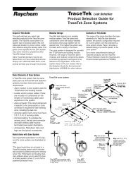
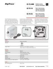
AFElectronic contro ler for hot watertemperature maintenance systems<strong>HWAT</strong> ® -<strong>ECO</strong><strong>Install</strong>ation and <strong>Operation</strong><strong>Manual</strong>Item Qty DescriptionA 1 <strong>HWAT</strong>-<strong>ECO</strong> controllerB 1 Water heater sensor with 13 ft (4 m) cableC 2 Mounting screwsD 2 Mounting washersE 1 Aluminum tapeF 1 <strong>Manual</strong>Figure 1: Kit contentsBCDETable of Contents1. General Information1.1 Use of the <strong>Manual</strong> ....................................................................11.2 Features ....................................................................................11.3 Technical Data ..........................................................................21.4 Care and Maintenance ..............................................................51.5 <strong>HWAT</strong> Heating Cables ..............................................................51.5.1 Maintain temperature ....................................................51.5.2 <strong>Install</strong>ing the heating cables ..........................................51.5.3 Ground-fault protection..................................................61.5.4 Pre-<strong>Install</strong>ation testing ..................................................62. <strong>Install</strong>ation2.1 <strong>Install</strong>ing the Controller ............................................................72.1.1 Opening the controller....................................................72.1.2 Wall mounting the controller..........................................82.2 Wiring the Controller ..............................................................102.2.1 Water heater sensor ....................................................132.2.2 Alarm wiring ................................................................152.2.3 Network........................................................................162.2.4 Building Management System (BMS) ..........................182.2.5 Closing the controller ..................................................203. Programming the Controller3.1 Programming Overview ..........................................................223.2 Initializing the Controller ........................................................233.2.1 Time and Date ..............................................................243.2.2 Cable type ....................................................................243.2.3 Voltage ........................................................................243.2.4 Units ............................................................................243.2.5 Ambient temperature....................................................243.2.6 Maintain temperature ..................................................253.2.7 Economy temperature ..................................................263.2.8 Default programs ........................................................263.2.9 Water heater sensor ....................................................263.3 Advanced Programming ..........................................................283.3.1 Time and Date ..............................................................30iiiii
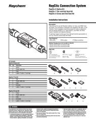
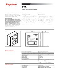
3.3.2 Setup............................................................................303.3.3 Timer............................................................................333.3.4 Holiday ........................................................................353.3.5 Info ..............................................................................354. Troubleshooting Guide ................................................365. Pre-Defined Programs ..................................................................38Heat-Up Cycle Graphs ..................................................................40Cool-Down Graph ..........................................................................423.4"(85 mm)6.5"(165 mm)ABCDEFGHGeneral Information11.1 Use of the <strong>Manual</strong>This manual covers the installation and operation of the<strong>HWAT</strong>-<strong>ECO</strong> controller and must be used with the followingadditional documents:• <strong>HWAT</strong> System Product and Selection Design Guide(H57538)• <strong>HWAT</strong> System <strong>Install</strong>ation and <strong>Operation</strong> <strong>Manual</strong>(H57548)Important: For the Tyco Thermal Controls warrantyand agency approvals to apply, the instructions includedin this manual and product packages must be followed.ABCDEFGH2 ea - 1/2" conduitentriesPower supply (green LED)Power to heating cable (green LED)Heat-up cycle (green LED) - increased risk of scaldingWater heater alarm (requires installed sensor) that lowers maintaintemperature if water heater temperature is too low (green LED)Alarm (red LED)Escape, backspace; NO; or display maintain temperature setpointArrow keys: to change menu selection or position the cursorConfirm selection, new value or YESFigure 2: <strong>HWAT</strong>-<strong>ECO</strong> controllerTo water heater sensorTo <strong>HWAT</strong>-<strong>ECO</strong> network/alarmentries1.2 FeaturesThe Raychem <strong>HWAT</strong>-<strong>ECO</strong> controller is designed for operationwith <strong>HWAT</strong>-Y2 and <strong>HWAT</strong>-R2 self-regulating heatingcables. The <strong>HWAT</strong>-<strong>ECO</strong> controller provides the followingfeatures:• Flexible temperature control of hot water temperaturemaintenance systems.• Integrated function that lowers the maintain temperatureduring low use hours to save energy.• Heat-Up cycle function that increases the water temperaturein a stagnant pipe.• Building Management System (BMS) interface thatreceives a DC voltage to set the maintain temperature.• Alarm relay to signal power, temperature, orcommunication problems.iv1
1General Information1General Information• Water heater sensor function that alarms and lowersthe maintain temperature if the water heater temperatureis too low.• Master/slave function that allows one <strong>HWAT</strong>-<strong>ECO</strong> tocontrol up to eight additional <strong>HWAT</strong>-<strong>ECO</strong> controllers.• 9 pre-defined programs that can be customized by theuser.1.3 Technical DataUseOnly for <strong>HWAT</strong>-Y2 and<strong>HWAT</strong>-R2 heating cablesMaintain temperature 105˚F (40˚C) to 140˚F (60˚C)setpointController ambient 40˚F (5˚C) to 105˚F (40˚C)temperatureambientSwitching capacity 24 A 208/240 Vac max.SPSTOperating voltage 208/240 (±10%), 60 HzInternal power consumption 2.5 WCircuit protection Max. 30 A with 30 mAground-fault protectionPower terminal block 16 – 10 AWG (1.5 – 4 mm 2 )Use copper conductors only.Internal temperature alarm 185˚F (85˚C)BMS control voltage 0 – 10 VdcAlarm contacts Max. 24 Vdc or 24 Vac, 1A,SPST, voltage freeAlarm eventsLoss of powerController reinitializedInternal controllertemperature too highWater heater temperaturetoo highWater heater temperaturetoo lowMaster/slave errorPower correction factor To increase or decreaseyour actual pipe maintaintemperatureWater heater sensor Thermistor with 13 ft 3 in(4 m) leadElectromagnetic Complies to EN 50081-1/2Compatibility (EMC) for emission and EN50082 -1/2 for immunityReal time clockAutomatic daylight savingstime and leap year correctionClock accuracy±10 minutes per yearEnclosure ratingNEMA 12 (IP52) – indooruse onlyEnclosure material ABSMountingWall mount with two screwsor optional DIN railConduit entries2 ea – 1/2 in conduit entries.23
1General Information1General InformationCable gland3-hole grommetMaximum cable size:• 2-wire: 20 AWG (.5 mm 2 )• 4-wire: 24 AWG (.2 mm 2 )Default programs 9 pre-defined programs thatcan be customized by userProgram settings 48 1/2-hour time blocks ofthe following program settings:Off, Economy,Maintain and Heat-Up cyclePassword4-digit password protectionMaster/slaveMaster is selectable in thecontroller, up to 8 slavescan be connectedMaster/slave cable 2-wire, min. 24 AWG (.2mm 2 ) twisted pair andinsulation of 300 VParameters in memory All parameters are stored innon-volatile memory, excepttime and dateClock backup time 8 hours ±10%ApprovalsWeight2 lbs (1 kg)Size 6.5 in x 3.4 in x 2.8 in (165mm x 85 mm x 71 mm)80BJType 12Energy Management Equipment1.4 Care and MaintenanceTo clean the <strong>HWAT</strong>-<strong>ECO</strong> use a damp cloth. Do not usesolvents. Do not pour water directly on the device. Do notuse a water hose or high pressure cleaner.In case of questions or product failure, pleasecontact your Tyco Thermal Controls representative,or call Tyco Thermal Controls at (800) 545-6258.1.5 <strong>HWAT</strong> Heating Cables1.5.1 Maintain temperatureDepending on the ambient temperature and voltage,<strong>HWAT</strong>-Y2 is designed to maintain temperatures up to125˚F (52˚C), and <strong>HWAT</strong>-R2 is designed to maintaintemperatures up to 140˚F (60˚C).1.5.2 <strong>Install</strong>ing the heating cables<strong>Install</strong> the <strong>HWAT</strong> heating cable system as instructed inthe <strong>HWAT</strong> System <strong>Install</strong>ation and <strong>Operation</strong> <strong>Manual</strong>(H57548). The controller must be installed by a professionalelectrical installer familiar with electrical safetycodes and practices.Verify that the heating cable circuit length does notexceed the values shown in Table 1:45
1General Information2<strong>Install</strong>ationTable 1: Maximum circuit length in feet (meters)Breaker <strong>HWAT</strong>-Y2 <strong>HWAT</strong>-R2Size @208/240-volt @208/240-volt30 Amp 800 (240) 500 (150)20 Amp 500 (150) 330 (100)15 Amp 350 (105) 250 (75)1.5.3 Ground-fault protectionWARNING: To minimize the danger of fire fromsustained electrical arcing if the heating cable is damagedor improperly installed, and to comply with therequirements of Tyco Thermal Controls and nationalelectrical codes, you must use 30-mA ground-faultequipment protection on each heating cable branch circuit.Arcing may not be stopped by conventional circuitprotection. The <strong>HWAT</strong>-<strong>ECO</strong> does not include groundfaultprotection.2.1 <strong>Install</strong>ing the Controller<strong>Install</strong> the controller in an indoor, dry, clean, accessiblelocation. If using a water heater sensor, make sure youinstall the controller within 328 ft (100 m) of the waterheater.2.1.1 Opening the controllerWARNING: To prevent shock, always switch off thepower supply (circuit breaker) before opening the controller.The <strong>HWAT</strong>-<strong>ECO</strong> has a removable front cover. Both thecover and the box have electronic parts and are connectedto each other by a 14-pin connector. First unscrew thefour screws in the cover. Carefully pull the cover straightout, not sideways! Inside the controller an ABS separationsheet will help to guide the connector when disconnecting.1.5.4 Pre-<strong>Install</strong>ation testingPrior to installing the <strong>HWAT</strong>-<strong>ECO</strong> controller, do an insulationresistance (Megger) test on the heating cable asdetailed in the <strong>HWAT</strong> System <strong>Install</strong>ation and <strong>Operation</strong><strong>Manual</strong> (H57548).Figure 3: Opening the controller67
2<strong>Install</strong>ation2<strong>Install</strong>ation2.1.2 Wall mounting the controllerMount the controller using either of the options below:1.You can mount the controller to the wall using the twosupplied screws and sealing rings in the two holeslocated inside the bottom part of the controller.2.Or you can mount the controller using DIN 35 Railmounting.Optional Din Rail(Rail not provided)1.7"(43 mm)5.9" (148 mm)MountingFigure 4: Hole locations for mounting with screwsRemovingPress tab to remove boxFigure 5: Mounting with DIN 35 Rail89
2<strong>Install</strong>ation2<strong>Install</strong>ation2.2 Wiring the ControllerThe diagram below shows the arrangement of theterminal blocks for power, alarm, water heater sensor,BMS and network.The diagram below shows the connection of a singlecontroller (without optional water heater sensor, BMS,network and alarm connections).Note: Put the terminal screws in place andtighten to 6 inch-lbs. (.68 N-m)To<strong>HWAT</strong>heatingcableWiring diagramfor <strong>HWAT</strong>-<strong>ECO</strong>Incoming power208/240 Vac MaxGroundFigure 6: General arrangement for terminal blocks1/2"ConduitsØØGMax. 30Aground faultcircuit breaker208-240 VacRayClic-PC<strong>HWAT</strong>heatingcableFigure 7: Connecting a single controller (w/o sensor,BMS, network and alarm connections)1011
2<strong>Install</strong>ation2<strong>Install</strong>ationFor controlling multiple <strong>HWAT</strong> circuits with the sameprogramming parameters (i.e. voltage, maintain temperature,ambient temperature, economy temperature),connect the heating cable output relay to an externalcontactor coil(s).Contact your Tyco Thermal Controlsrepresentative for more informationon how to integrate the <strong>HWAT</strong>-<strong>ECO</strong>with a Tyco Thermal Controls powerdistribution panel.Three-polemain circuitbreakerThree-polemaincontactorTwo-polewith 30-mAground-fault trip(208/240 Vac)Two-polewith 30-mAground-fault trip(208/240 Vac)ø 1ø 2ø 3 NC<strong>HWAT</strong>-<strong>ECO</strong> ControllerNCPanel energized lightContactor coil(208 or 240V)<strong>HWAT</strong>-<strong>ECO</strong> internal switchGroundLine voltage208V or 240VPowerconnectionHeating cableEnd seal<strong>HWAT</strong>heatingcableBraid/pipe<strong>HWAT</strong>heatingcable2.2.1 Water heater sensor (optional usage)<strong>Install</strong>ation of the water heater sensor is optional. Ifinstalled, the water heater sensor ensures that the <strong>HWAT</strong>-<strong>ECO</strong> maintain temperature does not exceed the waterheater temperature.The temperature sensorshould be connected toa single or master controlleronly. Connectboth wires of the temperaturesensor to theTEMP terminal in thecontroller (PL4). Thesensor wires do nothave a special polarity.To connect a wire, use ascrewdriver to pushdown the orange tab onthe side of the terminal.Put the wire into thehole and release theorange tab.Alarm,Sensor,and BMSterminalsPL3B APL4TEMPPL6PL5BMSAlarm contactFigure 9: TEMP terminal locationFigure 8: Multiple <strong>HWAT</strong> circuits connection1213
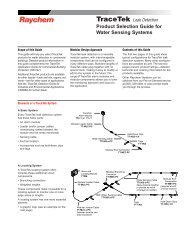
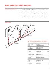
2<strong>Install</strong>ation2<strong>Install</strong>ation<strong>HWAT</strong>-Y2<strong>HWAT</strong>-R2AIf your system does not include a mixing valve, positionthe water heater sensor approximately 8 in (20 cm) fromthe water heater shown as A in Figure 10.If your system includes a mixing valve, position the waterheater sensor as close as possible to, but downstreamfrom, the mixing valve shown as B in Figure 10.Fold the metal tabs that are located on the sensor aroundthe hot water output pipe. Use the aluminum tape (included)to attach the water heater sensor to the pipe. Coverthe sensor and at least 8 in (20 cm) of the sensor cablewith insulation.Always keep the heating cable at least 8 in (20 cm) awayfrom the water heater sensor as shown in Figure 10.The water heater sensor cable is 13 ft 3 in (4 m) inlength, however the user can extend the cable up to 328 ft(100 m). The wire used to connect the temperature sensorto the <strong>HWAT</strong>-<strong>ECO</strong> should have a basic insulation of300 V and a solid core of at least 18 AWG (0.75 mm 2 ).Min. 8"(200 mm)Min. 8"(200 mm)insulationHot water inBHot water outTempered water out2.2.2 Alarm wiring (optional)The alarm contact (24 Vac, 24 Vdc, 1A) inside the controllercan be used to switch an external device. The contactis closed during operation and open during an alarmor during loss of power. In a network, all alarm contactsshould be connected in series.The alarm terminal (PL6)is located in the upperright corner of the controllerand has the text“alarm contact” next to it.To connect a wire, use ascrewdriver to pushdown the orange tab onthe side of the terminal.Put the wire into the holeand release the orangetab. The wires used forthe alarm contact shouldbe rated for 300 V. See“Chapter 4,Troubleshooting Guide”for more informationabout alarm conditions.Alarm,Sensor,and BMSterminalsPL3B APL4TEMPPL6PL5BMSAlarm contactFigure 11: Connectingthe alarm contactWaterheatermixingvalveCold water inFigure 10: Positioning water heater sensor1415
2<strong>Install</strong>ation2<strong>Install</strong>ation2.2.3 NetworkThe Master/slave function allows one <strong>HWAT</strong>-<strong>ECO</strong> tocontrol up to eight additional <strong>HWAT</strong>-<strong>ECO</strong> controllers.Connect all <strong>HWAT</strong>-<strong>ECO</strong> controllers to each other in parallelusing the A and B inputs on terminal (PL3). This meansthat several controllers will have two wires in one hole.The wire should be a twisted pair and be rated for 300 V.The total maximum length of this cable between all controllersis 328 ft (100 m). Be careful not to mix A and Bconnections. To connect a wire, use a screwdriver to pushdown the orange tab on the side of the terminal. Put thewire into the hole and release the orange tab.The diagram below shows the connection of multiplecontrollers (with optional RS-485 connections).B ANETWORK WIREMASTER SLAVE 1TEMPWATER HEATER SENSORBMS+ -OPTIONAL BMSTO SLAVE 2B AFigure 12: Networking controllers togetherTEMPBMS+ -Figure 13: Connecting multiple controllers (w/ RS-485)max. 20 AWGmax. 24 AWG(.5 mm 2 )(.2 mm 2 )When multiple controllersare networked and youare using BMS and Alarmfunctions, you must use a4-wire conductor.Figure 14: Combine alarm and BMS wire in 4-wirecableNote: For master/slave combination with alarmfunction, the alarms are connected in series by aRS485 wire. Since the cable gland grommet has only 3holes, you must combine the alarm wire and the BMSwire in a 4-wire cable.1617
2<strong>Install</strong>ation2<strong>Install</strong>ation2.2.4 Building Management System (BMS) (optional)See Table 6: BMS Voltage Input (pg 32).The BMS input of the<strong>HWAT</strong>-<strong>ECO</strong> is an analogue0 to 10 Vdcinput. If the controlleris programmed tohave a BMS connection,the BMS controlsthe temperaturesetpoint. Using 300 Vrated cable, connectthe BMS signal wireto terminal (PL5).Connect the groundwire to the “–” andthe 0-10 V output tothe “+” terminal.Alarm,Sensor,and BMSterminalsPL3B APL4TEMPPL6PL50-10vgroundBMSAlarm contactThe diagram below shows the connection of a singlecontroller (with optional sensor, BMS and alarmconnections).MasterL L208/240VRayClic-PCAlarmBMSSensor<strong>HWAT</strong>heatingcableFigure 15: Connecting the BMSFigure 16: Single controller connection (w/ sensor,BMS, and alarm connections)1819
2<strong>Install</strong>ation3Programming the Controller2.2.5 Closing the controllerPosition the cover in front of the wall-mounted box.The separation sheet inside the controller will help guidethe cover and the connector. Push the cover onto the box.Note that the connector pins will offer some resistance.Put the screws in place and tighten to 10 inch-lbs.(1.13 N-m).02-11-2004 09:30Maintain *ABCDEFGHFigure 17: Closing the controllerABCDEFPower supply (green LED)Power to heating cable (green LED)Heat-up cycle (green LED) - increased risk of scaldingWater heater alarm (requires installed sensor) that lowers maintaintemperature if water heater temperature is too low (green LED)Alarm (red LED)Escape, backspace; NO; or display maintain temperature setpointGArrow keys: to change menu selection or position the cursorHConfirm selection, new value or YESFigure 18: Controller display2021
3Programming the Controller3Programming the Controller3.1 Programming OverviewDisplay functionsThe display has two lines Quickstartwith 16 characters each. The Any key to startdisplay shows the followingtext on start up:The <strong>HWAT</strong>-<strong>ECO</strong> has six buttons:Up/Down/Left/Right arrowsEscape (ESC) buttonEnter buttonYou can program the <strong>HWAT</strong>-<strong>ECO</strong> by simply executing theQuickstart program which is suitable for normal operations.In addition, advanced programming can be used tomodify initial settings, set additional features such asBMS and Network Master, reinitialize the entire controller,or customize the pre-defined programs.3.2 Initializing the ControllerThe first time you power up the controller, you mustexecute the Quickstart program to set the initial settings:Table 2: Quickstart menuTime and Date Year Select YearMonth Select MonthDaySelect DayHourSelect HourMinutes Select MinutesCable Type <strong>HWAT</strong>-R2 "Press Enter for this cable type.'<strong>HWAT</strong>-Y2 "Press Enter for this cable type.'Voltage Select 208-Vac "Press Enter for this voltage type.'240-Vac "Press Enter for this voltage type.'Units English "Press Enter for this unit type.'Metric "Press Enter for this unit type.'Ambient Temp."Enter ambient temp."Maintain Temp."Enter maintain temp. setpoint"Economy Temp."Enter ecomomy temp. setpoint"Default program Constant 'Scroll to program and press Enter.'ApartmentsFamily homePrisonHospitalNursing homeHotelSports CenterConvalesc. homeWater heater sensor Off or On Select Off or On. If 'On', select Delta.2223
3Programming the Controller3Programming the ControllerDuring the Quickstart you can press the ESC button to goback to a previous menu. On startup the display will showthe following text:QuickstartAny key to startPress a key to start, and the following menus appear:3.2.1 Time and DateUse the up/down arrows to select the year and pressEnter. Then, select and enter the month, day, hour, andminutes.3.2.2 Cable typeUse the up/down arrows to select <strong>HWAT</strong>-Y2 or <strong>HWAT</strong>-R2cable used in your installation. Press Enter.3.2.3 VoltageUse the up/down arrows to select 208 V or 240 V (appliedvoltage to the cable). Press Enter.3.2.4 UnitsUse the up/down arrows to select English or Metric units.Press Enter.3.2.5 Ambient temperatureThe ambient temperature is the air temperature where theheating cable is installed. Use the up/down arrow keys toselect from 60˚F (15˚C) to 80˚F (25˚C). Press Enter.If your design requires that the ambient temperature issignificantly different from one location to another, youwill need an <strong>HWAT</strong>-<strong>ECO</strong> controller for each ambientcondition.3.2.6 Maintain temperatureThe maintain temperature setpoint is the water temperaturethat you set for normal use. Use the up/down arrowkeys to select the temperature.The minimum temperature is 105˚F (40˚C) or the economytemperature, whichever is higher. The maximum temperaturedepends on cable type, voltage and ambient temperature.The programmed maintain temperature will displayif you press the ESC button once the system is inoperation.Table 3: Maximum maintain temperature (208-volt)Ambient TemperatureHeating Cable 60˚F (15˚C) 70˚F (20˚C) 80˚F (25˚C)<strong>HWAT</strong>-Y2 115˚F (46˚C) 120˚F (49˚C) 125˚F (52˚C)<strong>HWAT</strong>-R2 140˚F (60˚C) 140˚F (60˚C) 140˚F (60˚C)Table 4: Maximum maintain temperature (240-volt)Ambient TemperatureHeating Cable 60˚F (15˚C) 70˚F (20˚C) 80˚F (25˚C)<strong>HWAT</strong>-Y2 120˚F (49˚C) 125˚F (52˚C) 125˚F (52˚C)<strong>HWAT</strong>-R2 140˚F (60˚C) 140˚F (60˚C) 140˚F (60˚C)2425
3Programming the Controller3Programming the Controller3.2.7 Economy temperatureThe economy temperature setpoint is the water temperaturefor periods during which hot water is not usuallyused (at night) or when a lot of hot water is used (peakperiod). Use the up/down arrows to select the temperature.The minimum temperature is 105˚F (40˚C) and themaximum temperature is the selected maintain temperature.If the supplied water temperature is lower than your maintaintemperature setpoint, the setpoint is automaticallylowered to the highest temperature measured over thelast 24 hours, minus the temperature delta that youentered. In any case, the maintain temperature will not belower than 105˚F (40˚C). When the <strong>HWAT</strong>-<strong>ECO</strong> has overwrittenthe user-defined maintain temperature, the waterheater sensor function is active and will alarm by lightingthe LED and activating the alarm relay.3.2.8 Default programsThe <strong>HWAT</strong>-<strong>ECO</strong> has 9 pre-defined programs. (See“Chapter 5, Pre-Defined Programs” for more information.)Use the up/down arrows to select a pre-defined program.Press Enter. <strong>HWAT</strong>-<strong>ECO</strong> takes a few seconds to copy thepre-defined program to the internal memory. During thistime a row of dots will show in the display.3.2.9 Water heater sensor (optional)When the water heater sensor option is activated and thesensor is installed per section 2.2.1, the <strong>HWAT</strong>-<strong>ECO</strong> controllermonitors the temperature of the water being suppliedto the system and ensures that the maintain temperatureof the heating cable does not exceed the suppliedwater temperature. The <strong>HWAT</strong>-<strong>ECO</strong> controller stores thehighest water heater temperature measured over the last24 hours. You can toggle the setting between OFF and ONusing the up/down arrow buttons. If ON, you will beprompted to select the desired temperature delta betweenthe supplied water temperature and the maintain temperaturesetpoint. Allowable delta is between (9˚F [5˚C] and27˚F [15˚C]). Press Enter.Completing initializationThe controller will start automatically when you finishselecting your Quickstart options. Additional settings areavailable in the Setup menu for advanced installations.See section “3.3 Advanced Programming” for more information.Press Enter to start the controller. If you press the ESCbutton, you can retrace all menu items to check the settings.After starting the controller the display shows date,time, temperature setting and a “*” to indicate that thecontroller is unlocked. If you wish to lock (password protect)the controller, see section 3.3.2.6 for instructions.2627
3Programming the Controller3Programming the ControllerDisplaying Maintain Temperature SetpointAfter finishing theQuickstart, the displaywill show the date,time, temperature mode and a star to indicate that thecontroller is unlocked.While in operating mode, press ESC to view a bar graphthat shows the maintain temperature setpoint. To enterthe programming menu, press any other key. The controllerwill exit the menu automatically after five secondsof key inactivity.Figure 19: Bar graph3.3 Advanced Programming02-11-2004 09:13Maintain *Advanced programming options are also available.Table 5 and remainder of this section outline the advancedprogramming options that include modifying initial settings,setting additional features such as BMS andNetwork Master, reinitializing the entire controller, orcustomizing the pre-defined programs.Table 5: Advanced programming menu1 Time and Date 1 Year Select Year2 Month Select Month3 Day Select Day4 Hour Select Hour5 Minutes Select Minutes2 Setup 1 Maintain Temp. "Enter maintain temp. setpoint"(enter password 2 Economy Temp. "Enter economy temp. setpoint"if Lock is On) 3 Ambient Temp. "Enter ambient temp."4 Power Correction Selectable5 Water heater Select Off or On6 Lock Lock/unlock Setup and Timer menus7 BMS Select Yes/No8 NetworkMaster Select Yes/No9 Reinitialize Select Yes/No3 Timer 1 Default program Constant(enter passwordApartmentsif Lock is On)Family homePrisonHospitalNursing homeHotelSports CenterConvalesc. home2 Edit program Monday Edit timer for MondayTuesday Edit timer for TuesdayWednesday Edit timer for WednesdayThursday Edit timer for ThursdayFriday Edit timer for FridaySaturday Edit timer for SaturdaySunday Edit timer for Sunday4 Holiday OnOffxx Days off5 Info Show firmware version number + Cable type + Sensor temp.2829
3Programming the Controller3Programming the Controller3.3.1 Time and DateUse the up/down arrows to select the year and pressEnter. Then select and set the month, day, hour andminutes.3.3.2 SetupWhen Lock is on (no star in the lower right corner) entera password to access the setup menu. The controllerlocks again after 60 seconds of inactivity.When Lock is off the following menus are directlyaccessible.1. Maintain temperatureThe maintain temperature setpoint is the water temperaturethat you set for normal use. Use the up/down arrowsto select the temperature. The minimum temperature is105˚F (40˚C) or the economy temperature, whichever ishigher. The maximum temperature depends on cabletype, pipe diameter, insulation thickness and ambienttemperature.2. Economy temperatureThe economy temperature setpoint is the watertemperature for periods during which hot water is notusually used (at night) or when a lot of hot water is used(peak period). Use the up/down arrows to select thetemperature. The minimum temperature is 105˚F (40˚C)and the maximum temperature is the selected maintaintemperature. Press Enter.3. Ambient temperatureThe ambient temperature is the air temperature where theheating cable is installed. Use the up/down arrows toselect from 60˚F (15˚C) to 80˚F (25˚C). Press Enter toconfirm.If your design requires that the ambient temperature issignificantly different from one location to another, youwill need an <strong>HWAT</strong>-<strong>ECO</strong> controller for each ambientcondition.4. Power correctionThe power correction factor can be selected to increase ordecrease your actual pipe maintain temperature.5. Water heater sensorThe water heater setting is included to ensure that theheating cable temperature does not exceed the waterheater temperature. The external temperature sensor isused to measure the water heater temperature.6. Lock (password)Use the up/down arrows to select Lock On/Off and pressEnter. If you select ‘On’, you must enter a password usingthe left/right and up/down arrow buttons to select a 4-digit password. Press Enter.You will need to remember your 4-digit password wheneveryou wish to unlock the controller for reprogramming.Once you unlock and reprogram, you will need to relockby entering your password.If Lock is On, the Setup and Timer menus are protectedby the password. After you enter the password, the3031
3Programming the Controller3Programming the Controller32controller remains unlocked until five minutes of key inactivityor until you select Lock ‘On’ again.7. Building Management System (BMS)Table 6: BMS Voltage Input<strong>HWAT</strong>-Y2<strong>HWAT</strong>-R2U-BMS/U-GLT(VOLT)Temp °F (°C)>147 (>64) X >6.4147 (64) X 6.4140 (60) X 6131 (55) X X 5.5122 (50) X X 5113 (45) X X 4.5106 (41) X X 4.1Off X X 0You can activate the BuildingManagement System optionusing this menu. When set to“Yes” the controller respondsonly to the voltage applied tothe BMS terminal. For voltages≤ 4 Vdc: heating cableis OFF. For voltages between4.1 Vdc and 6.4 Vdc: maintaintemperatures are set asindicated in Table 6: BMSVoltage Input. For voltages >6.4 Vdc: 100% power isapplied to the heating cable.See section 2.2.4 for installationinformation. If Water heater is ON, it overrules theBMS temperature setting if necessary.8. Network MasterIn large installations where more than one <strong>HWAT</strong>-<strong>ECO</strong>controllers are connected to each other, you must selectone controller as the Master. This controller should befully programmed and all slave controllers will use theMaster settings.The master controller sends commands to all slave controllersto switch them ON or OFF. The master program isused for all controllers as follows: Slave controllers on thesame phase (max. three controllers) will have a delayedON and OFF. This way the start-up current of the cable willnever occur at the same moment for these controllers (A,B and C). Slave controllers connected to a different phasewill switch at the same time (1, 2 and 3).After selecting “Master: Yes”, the slave controllers willinitialize and show::Slave: x y” x= phase number (1 to 3)y= slave identification (A, B and C)The master controller is always 1 A, the slave controllerswill get their number and identification automatically.Always check afterwards if all controllers have unique idnumbers,if not, check the RS485 cables and repeat thisprocedure.9. ReinitializeTo Reinitialize all settings back to the factory settings(except time and date), set the “Reinitialize” menu to “Yes.”3.3.3 TimerThe Timer feature lets you re-program any of the predefinedprograms to suit your personnel requirements.Reprogramming is done graphically in 1/2 hour timeblocks. A block can be set to Heat-Up cycle, Maintaintemperature, Economy temperature, or Off. See “Chapter 5,Heat-Up Graphs” for more information.Edit pre-defined programsTo edit a program, switch Lock to Off. You will need toenter a password to unlock the controller. After you enterthe password, the controller remains unlocked until fiveminutes of key inactivity or the Lock ‘On’ is selected again.33
3Programming the Controller3Programming the ControllerSelect temperatureUse the up/down arrows to select the temperature:= Heat-up cycle= Economy temperature = OffFigure 20: Timer block options= Maintain temperatureSelect time blockUse the left/right arrows to select the time block. Timerprogramming example from 00:00 to 08:00:hours. When hot water is not being used and the pipes arestagnant, the <strong>HWAT</strong>-<strong>ECO</strong> can raise the temperature of thewater in the stagnant pipes. To determine the amount oftime that is required to reach a desired temperature, referto “Chapter 5, Heat-Up Graphs.” You must know the programmedmaintain temperature, pipe sizes, system voltageand the type of heating cable to determine the amount oftime that is required to reach a desired temperature. If thedesired temperature can be reached in a timeframe that isless than when the pipes will be flowing again, the Heat-Upcycle can be programmed for the number of hours that arerequired and the desired temperature will be reached. Todetermine the amount of time that is required to returnback to the maintain temperature after the Heat-Up cycle iscomplete and the heating cable is off, refer to “Chapter 5,Cool-Down Graph.”3.3.4 HolidayThis menu is used to set the controller to Off, timed-off, orto resume your timer program.On: The controller starts using the timer program.Off: The controller will not power the system until youselect “Use timer”.xx Days off: You can select a number of days. The controllerautomatically returns to timer mode when theselected number of days have passed...........00:00 – 00:30: Heat-up cycle00:30 – 01:00: Heat-up cycle01:00 – 01:30: Heat-up cycle01:30 – 02:00: Heat-up cycle02:00 – 02:30: Off02:30 – 03:00: Off03:00 – 03:30: Off03:30 – 04:00: Off04:00 – 04:30: Off04:30 – 05:00: Economy05:00 – 05:30: Economy05:30 – 06:00: Economy06:00 – 06:30: Economy06:30 – 07:00: Maintain07:00 – 07:30: Maintain07:30 – 08:00: Maintain..........Figure 21: Timer programming exampleHeat-Up cycleThe <strong>HWAT</strong>-<strong>ECO</strong> can be programmed to power <strong>HWAT</strong>-Y2or <strong>HWAT</strong>-R2 at full power for any selected number of3.3.5 InfoThe display shows the firmware version number, selectedcable type and the current sensor temperature. Press Entertwice to update the sensor temperature on the display.3435
4Troubleshooting GuideSymptom Probable Causes Corrective ActionWater heater alarm light is onClock reset to default"01.01.2001 00:00" displays"ALARM 1" displays(buzzer beeping simultaneously;and error LED " " on)"ALARM 2" displays(buzzer beeping simultaneously;and error LED " " on)"ALARM 3" displaysCheck network(buzzer beepingsimultaneously; and errorLED " " on)"Mode Quickstart" displaysNo displayWater temperature too lowWater temperature too high1. Water heater temperature is lower than maintaintemperature setpoint of the <strong>HWAT</strong>-<strong>ECO</strong>.1. No power supply for more than 8 hours.1. Internal temperature of <strong>HWAT</strong>-<strong>ECO</strong> higher than185°F (85°C).1. Water heater temperature too high.2. Sensor has not been installed.3. Sensor or sensor cable defect (only when waterheater sensor "On" is selected).1. 2 or more controllers are active as ‘Master’.2. 'Master' has been initialized but 1 or morecontrollers are unpowered or are disconnectedfrom the network while initializing.3. No 'Master' initialized.1. Alarm sounds when user is initializing orreinitializing the system.1. Loss of power.1. Water heating cable temperature is too low.2. <strong>Install</strong>ed heating cable is different from theprogram selected.3. Insulation thickness deviates from the requiredinsulation thickness.4. The ambient temperature value entered is too high.1. Water heating cable temperature is too high.2. Insulation thickness deviates from the requiredinsulation thickness.3. The ambient temperature value entered is too low.Check water heater temperature (also indicated in INFO of <strong>HWAT</strong>-<strong>ECO</strong> menu; see 3.3.2.1).Check maintain temperature setting at <strong>HWAT</strong>-<strong>ECO</strong>. Check temperature sensor mounting.Update date and time (see 3.3.2.1).Switch off or disconnect power supply and contact Tyco Thermal Controls representative.(1) Lower water heater temperature.(2) Connect sensor to <strong>HWAT</strong>-<strong>ECO</strong> or set program and error LED water heater sensor OFF.(3) Check sensor connections. Replace sensor. Check water heater sensor mounting andlocation.(1, 2, 3) Reinitialize the 'Master' (see 3.3.2.9).Alarm will clear when user completes the initialization or reinitialization process.Restore power.(1) Check water heater temperature and timer program.(2) Change heating cable type in <strong>HWAT</strong>-<strong>ECO</strong> (can only be done in Quickstart (see 3.3.2.9).(3) Adjust power correction factor (see 3.3.2.4).(4) Change value of ambient temperature (see 3.3.2.3).(1) Change heater type in <strong>HWAT</strong>-<strong>ECO</strong> (can only be done in Quickstart (see 3.3.2.9).(2) Adjust power correction factor (see 3.3.2.4)(3) Change value of ambient temperature (see 3.3.2.3)Can't access programming mode361. Controller is password-protected.Enter your 4-digit password. If you forgot your password,enter the backup password: 6922 to unlock the controller.37
5Pre-Defined Programs= Heat-up cycle= Maintain temperature= Heat-up cycle= Maintain temperature= Economy temperature = Off= Economy temperature = OffI-0Heat-upMaintainMonday-Sunday EconomyConstantI-4Heat-upMaintainMonday-Sunday EconomyHospitalI-1OffHeat-upMaintainMonday-Friday EconomyOffHeat-upMaintainSaturday-SundayEconomy00 02 04 06 08 10 12 14 16 18 20 22 24Apartments00 02 04 06 08 10 12 14 16 18 20 22 24maxI-5I-6Heat-upHeat-upMaintainMonday-Sunday EconomyOff00 02 04 06 08 10 12 14 16 18 20 22 24Nursing homeMaintainMonday-SundayEconomyOff00 02 04 06 08 10 12 14 16 18 20 22 24HotelI-2MaintainMonday-Sunday EconomyOff00 02 04 06 08 10 12 14 16 18 20 22 24Heat-upFamily homeI-7Heat-upMaintainMonday-Sunday EconomyOff00 02 04 06 08 10 12 14 16 18 20 22 24Sports centerI-3MaintainMonday-Sunday EconomyOff00 02 04 06 08 10 12 14 16 18 20 22 24Heat-upPrisonI-8Heat-upMaintainMonday-Sunday EconomyOff00 02 04 06 08 10 12 14 16 18 20 22 24Convalesent homeOff00 02 04 06 08 10 12 14 16 18 20 22 24Off00 02 04 06 08 10 12 14 16 18 20 22 243839
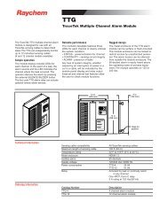
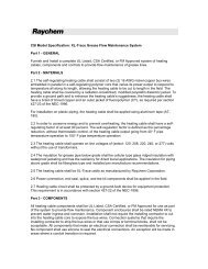
5Heat-Up Cycle Graphs125(52)Heat-Up <strong>HWAT</strong>-Y2150(66)Heat-Up <strong>HWAT</strong>-R2Pipe Temperature °F (°C)120(49)115(46)110(43)208V1/2-inch pipe1-inch pipe2-inch pipe70°F (21°C) ambient105(41) 0 2 4 6 8 10 12 14 16 18 20 22 24Time (hours)125(52)Pipe Temperature °F (°C)140(60)130(54)120(49)150(66)208V1/2-inch pipe1-inch pipe2-inch pipe110(43) 70°F (21°C) ambient105(41)0 2 4 6 8 10 12 14 16 18 20 22 24Time (hours)Pipe Temperature °F (°C)120(49)115(46)110(43)240V1/2-inch pipe1-inch pipe2-inch pipe70°F (21°C) ambient105(41)0 2 4 6 8 10 12 14 16 18 20 22 24Time (hours)Pipe Temperature °F (°C)140(60)130(54)120(49)110(43)105(41)70°F (21°C) ambient240V1/2-inch pipe1-inch pipe2-inch pipe0 2 4 6 8 10 12 14 16 18 20 22 24Time (hours)4041
5Cool-Down Graph150(66)145(63)140(60)Cool-Down70°F (21°C) ambient1/2-inch pipe1-inch pipe2-inch pipe135(57)Pipe Temperature °F (°C)130(54)125(52)120(49)115(46)110(43)105(40)0 1 2 3 4 5 6 7 8 9 10 11 12Time (hours)4243
Tyco, Raychem and <strong>HWAT</strong> are trademarks of Tyco Thermal Controls LLC or itsaffiliates.Megger is a trademark of Megger Limited.Important: All information, including illustrations, is believed to be reliable.Users, however, should independently evaluate the suitability of each productfor their particular application. Tyco Thermal Controls makes no warranties asto the accuracy or completeness of the information, and disclaims any liabilityregarding its use. Tyco Thermal Controls only obligations are those in theTyco Thermal Controls Standard Terms and Conditions of Sale for this product,and in no case will Tyco Thermal Controls or its distributors be liable forany incidental, indirect, or consequential damages arising from the sale, resale,use, or misuse of the product. Specifications are subject to change withoutnotice. In addition, Tyco Thermal Controls reserves the right to makechanges—without notification to Buyer—to processing or materials that donot affect compliance with any applicable specification.U.S.A.Tyco Thermal Controls300 Constitution DriveMenlo Park, CA 94025-1164 USATel (800) 545-6258Fax (800) 596-5004info@tycothermal.comwww.tycothermal.comCanadaTyco Thermal Controls250 West St.Trenton, OntarioCanada K88V 55S2Tel (800) 545-6258Fax (800) 596-5004© 2004 Tyco Thermal Controls LLC P000000241 H57340 05/0444