Kenco
Kenco
Kenco

You also want an ePaper? Increase the reach of your titles
YUMPU automatically turns print PDFs into web optimized ePapers that Google loves.
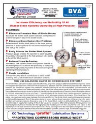
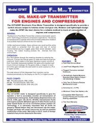
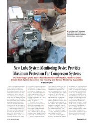
NO FLOW SAFETY SWTICHNO-FLOW SAFETY SWITCHCompressor and Engine CylinderProtection Against Lubrication Failure* Fail-Safe wear pattern.No dangerous “shoulder” to prevent shutdown sothat switch is always functional with clean oil aboveits pour point.* Shutdown time adjustable over a wide range* Explosion-proof models available* Overpressure rupture assembly optional* Switch contact rating - 2A at 30 VAC / DCThe <strong>Kenco</strong> No-Flow Switch mounts in the line between the lubricator and cylinder. Oil flow is through the switch --forcing the plunger off its contact. Its rate of travel is controlled by fluid slippage past the precision-fit plunger,preventing premature shutdown. If the lubricator stops pumping, the plunger will drift to the contact and stop theengine. On start up, the first stroke of the lubricator automatically opens the switch. In operation the plunger canpump out of its hole on very high feed rates and does not obstruct flow. The time interval between lubricationfailure and shutdown can be adjusted by increasing or decreasing the compression on the spring.The switch is available with an overpressure rupture assembly which will instantaneously bleed off and stop theengine in the event the lube-line check-valve plugs. The standard rupture disc fails at 1750 psi. Other rupturepressureavailable on request.The non-explosion proof switch has been tested to 5,000 psi. Its maximum recommended working pressure is2,000 psi. The explosion-proof switch has been tested to 15,000 psi and its recommended working pressure is8,600 psi.EQUIPTMENT SPECIFICATIONSNFS-3: No-Flow Switch without mounting bracketNFS-4: No Flow Switch with mounting bracket for AjaxNFS-5: Triple No-Flow Switch with mounting bracketNFS-7: No-Flow Switch with overpressure rupture assemblyNFS-9: No-Flow Switch with overpressure rupture assemblyand mounting bracket for AjaxNFS-25: Explosion-Proof No-Flow Switch with overpressurerupture assembly for large Ajax (3 switches on onebracket)NFS-6: Explosion-Proof No-Flow Switch
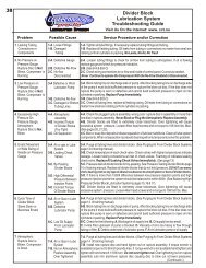
PARTS LIST AND INSTRUCTIONSPARTS LIST AND INSTRUCTIONSDescription Part # Item # -3 -4 -5 -6 -7 -9 -25Body B-19188 1 1 1 3 - - - -Body-Explosion Proof B-19190 1 - - - 1 - - -Body-w/Rupture Disc Mtg. Hole B-19189 - - - - - 1 1 -Body-Explosion Proof w/ B-19191 1 - - - - - - 1Rupture Disc Mtg. HolePusher A-19185 2 1 1 3 1 1 1 1Spring A-794 3 1 1 3 1 1 1 1Piston B-19184 4 1 1 3 1 1 1 1Back-Up Ring P-19237 5 1 1 3 1 1 1 1O-Ring P-13011-B 6 1 1 3 1 1 1 1Adjustment Screw Housing B-19187 7 1 1 3 1 1 1 1O-Ring P-13015-B 8 1 1 3 1 1 1 1Set Screw P-19028 9 1 1 3 1 1 1 1Hex Nut P-1960 10 1 1 3 1 1 1 1Plunger A-19186 11 1 1 3 1 1 1 1Contact Switch A-687 12 1 1 3 - 1 1 -Contact Switch A-802 12 1 1O-Ring P-13013-B 15 1 1INSTALLATION AND OPERATING INSTRUCTIONS1. Switch MUST be mounted either vertically (terminal end up) or at a minimum angle of 20 º off horizontal with terminal end at the highpoint. This prevents water from accumulating around switch contact (see figure 2).2. A 25 micron sintered bronze or similar in-line type filter should be installed ahead of the no flow switch. These are available from eitherKENCO or most manufacturers of lubricators.3. To assure constant oil viscosity, mount switch in a warm place near cylinder lube-line check valve or point of lubrication. The “NFS-4”,“NFS-5” and “NFS-9” no flow switches for Ajax are provided with brackets for mounting to one of the screws which hold the cast cover tothe cylinder near the cylinder check. Connect no flow switch contact wire to magneto or alarm/shutdown switch.4. Connect line from lubricator to inlet port on no flow switch.5. Hand pump lubricator until oil flows from outlet port; then connect line from outlet to point of lubrication.6. Switch is factory adjusted for a shutdown time of approximately 3 minutes using SAE 30 oil at 100 º F. The switch is viscosity sensitive,therefore, shutdown time will vary with oil viscosity. Many compressor manufacturers indicate that 10-15 minutes operations aftercessation of lubricant flow is acceptable so it should not be necessary to make seasonal adjustments.7. If adjustments are necessary, ensure that adjustments are made while engine / compressor / no flow switch are at their normal operating conditions. The adjustment setscrew is located on bottom of switch housing. Turn setscrew IN to decrease shutdown time and OUT toincrease. Shutdown time can be determined by removing / disabling lubricator pumping unit. On multiple pump installations pumpingat the same rate, the setting can usually be transferred from one switch to another by making the distance from the end of the adjustmentsetscrew to the end of the adjustment setscrew housing equal on all switches (see figure 1).Represented by:TulsaPO Box 470426 Tulsa, OK 74147phone 918.663.4406 fax 918.663.4480http://www.kenco-eng.com email: info@kenco-eng.comBaton Rouge11616 Industriplex, Suite 14 Baton Rouge, LA 70809phone 504.755.1912 fax 504.755.1913http://www.kenco-eng.com