SERVICE PROGRAM
SERVICE PROGRAM
SERVICE PROGRAM
- No tags were found...

You also want an ePaper? Increase the reach of your titles
YUMPU automatically turns print PDFs into web optimized ePapers that Google loves.
<strong>SERVICE</strong> <strong>PROGRAM</strong>SP 2-201-001NOVEMBER 2007VIN List “A-WXLL” - WXLL vehicles which require a replacement fan ring seal(and the radiator shroud to fan ring space to be adjusted, and installation of the new fan ring seal)5VCHC6JF48H205479 5VCHC6JF08H205480 5VCHC6JF28H205481 5VCHC6JF48H2054825VCHC6KE48H205522 5VCHC6KE68H205523 5VCHC6KE88H205524 5VCHC6KEX8H2055255VCHC6KE18H205526 5VCHC6JFX8H205602 5VCHC6JF18H205603 5VCHC6JFX8H2056165VCHC6HE98H205619 5VCHC6HE58H205620 5VCHC6HE78H205621 5VCHC6KE08H2056295VCHC6KE78H205630 5VCHC6KE98H205631 5VCHC6KE08H205632 5VCHC6KE28H2056335VCHC6KE48H205634 5VCHC6KE68H205635 5VCHC6KE88H205636 5VCHC6KEX8H2056375VCHC6KE18H205638 5VCHC6KE38H205639 5VCHC6KEX8H205640 5VCHC6KE18H2056415VCHC6KE38H205642 5VCHC6KE58H205643 5VCHC6KE78H205644 5VCHC6KE98H2056455VCHC6KE08H205646 5VCHC6KE28H205647 5VCHC6KE48H205648 5VCHC6JF88H2056775VCHC6JFX8H205678 5VCHC6JE28H205679 5VCHC6JE98H205680 5VCH36JFX8H2056815VCH36JF18H205682 5VCH36JF38H205683 5VCH36JF58H205684 5VCH36JF78H2056855VCH36JF98H205686 5VCHC6JF48H205692 5VCHC6JF68H205693 5VCHC6KE08H2056945VCHC6KE28H205695 5VCHC6KE48H205696 5VCHC6KE68H205697 5VCH36HE38H2058125VCH36JF08H205835 5VCH36JF28H205836 5VCHC6KE68H205893 5VCHC6KE88H2058945VCHC6HE48H205897 5VCHC6HE68H205898 5VCHC6JF58H205930 5VCHC6JF78H2059315VCHC6JF98H205932 5VCHC6JF08H205947 5VCHC6JF28H205948 5VCHC6JF48H2059495VCHC6JF08H205950 5VCHC6JF28H205951 5VCHC6HE08H206030 5VCH36JF58H2060605VCH36JF78H206061 5VCHC6HE78H206087 5VCHC6HE98H206088 5VCHC6HE08H2060895VCHC6JF28H2060956 of 22AC-SP-263-0711-P28Questions? Visit the Autocar website atwww.autocartruck.com and click the Web Link Directicon to request emergency service assistance.
<strong>SERVICE</strong> <strong>PROGRAM</strong>SP 2-201-001NOVEMBER 2007VIN List “B-WX” - WX vehicles which DO NOT require a replacement fan ring seal(which still require adjusting the radiator shroud to fan ring space and securing the existing fan ring seal)5VCDC6JF68H205661 5VCDC6JF88H205662 5VCDC6JFX8H205663 5VCDC6JF18H2056645VCDC6JF38H205665 5VCDC6JF28H206015 5VCDC6JF48H206016 5VCDC6JF68H2060205VCDC6JF88H206021 5VCDC6JFX8H206022 5VCDC6JF18H206023 5VCDC6JF38H2060245VCDC6JF58H206025 5VCDC6JF78H206026 5VCDC6JF98H206027 5VCDC6JF08H2060285VCDC6JF28H206029 5VCDC6JF08H206031 5VCDC6JF28H206032 5VCDC6JF48H2060335VCDC6JF68H206034 5VCDC6JF88H206035 5VCDC6JF38H206041 5VCDC6JF58H2060425VCDC6JF78H206043 5VCDC6JF98H206044 5VCDC6JF08H206045 5VCDC6KF38H2060545VCDC6KF58H206055 5VCDC6KF78H206056 5VCDC6LE68H206099 5VCDC6LE98H2061005VCD36LE08H206101 5VCDC6JF58H206106 5VCDC6JF98H206108 5VCDC6JF08H2061095VCDC6JF78H206110 5VCDC6JF98H206111 5VCDC6JF08H206112 5VCDC6JF28H2061135VCDC6JF48H206114 5VCDC6KF88H206115 5VCDC6KFX8H206116 5VCDC6KF18H2061175VCDC6KF38H206118 5VCDC6KF58H206119 5VCDC6KF18H206120 5VCDC6KF38H2061215VCDC6KF58H206122 5VCDC6KF78H206123 5VCDC6KF98H206124 5VCDC6KF08H2061255VCDC6KF28H206126 5VCDC6KF48H206127 5VCDC6KF68H206128 5VCDC6KF88H2061295VCDC6JF28H206130 5VCDC6JF48H206131 5VCDC6JFX8H206134 5VCDC6JF58H2061375VCDC6JF78H206138 5VCDC6JF98H206139 5VCDC6JF58H206140 5VCDC6JF78H2061415VCDC6JF98H206142 5VCDC6KF18H206148 5VCDC6KF38H206149 5VCDC6KFX8H2061505VCDC6KF18H206151 5VCDC6KF38H206152 5VCDC6KF58H206153 5VCDC6KF78H2061545VCDC6KF98H206155 5VCDC6KF08H206156 5VCDC6KF28H206157 5VCDC6KF68H2061595VCDC6KF28H206160 5VCDC6KF48H206161 5VCDC6KF68H206162 5VCDC6KF88H2061635VCDC6KE28H206165 5VCDC6JF18H206166 5VCDC6JF38H206167 5VCDC6HE98H2061685VCDC6HE08H206169 5VCDC6HE78H206170 5VCDC6JF58H206171 5VCDC6JF78H2061725VCDC6JF98H206173 5VCDC6JF08H206174 5VCDC6KF48H206175 5VCDC6JF48H2061765VCDC6JF98H206187 5VCDC6JF08H206188 5VCD36HE68H206189 5VCDC6KF08H2061905VCDC6KF28H206191 5VCDC6KF48H206192 5VCDC6JF48H206193 5VCDC6JF68H2061945VCDC6JF88H206195 5VCDC6JFX8H206196 5VCDC6JF18H206197 5VCDC6JF38H2061985VCDC6JF58H206199 5VCDC6JF88H206200 5VCDC6JFX8H206201 5VCDC6JF18H2062025VCDC6JF38H206203 5VCDC6JF58H206204 5VCDC6JF78H206205 5VCDC6JF98H2062065VCD36HF58H206242 5VCD36HF78H206243 5VCD36HF98H206244 5VCDC6LE28H2062455VCDC6LE48H206246 5VCDC6KE48H206250 5VCDC6KE68H206251 5VCDC6KE88H2062525VCDC6KE38H206255 5VCDC6KE58H206256 5VCDC6KE78H206257 5VCDC6KE98H2062585VCDC6KE08H206259 5VCDC6KE78H206260 5VCDC6JF58H206266 5VCDC6JF78H2062675VCDC6JF98H206268 5VCDC6JF08H206269 5VCDC6KF98H206270 5VCDC6KF08H206271Questions? Visit the Autocar website atwww.autocartruck.com and click the Web Link Directicon to request emergency service assistance.7 of 22AC-SP-263-0711-P28
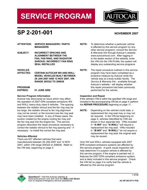
<strong>SERVICE</strong> <strong>PROGRAM</strong>SP 2-201-001NOVEMBER 2007REPAIR PROCEDURESTEP 1: Raise the cab●●●●WARNINGDue to the danger of sustaining personal injuryand/or damage to the vehicle, never attempt toraise the cab outdoors under extremely windyconditions. The strong wind conditions couldforce the cab beyond the normal limits of its travel.Remove or secure all loose articles andclose all doors before raising the cab. Thearea above and ahead of the cab must beclear from obstructions. Place front wheelsin a straight ahead position.Remove the pump handle from its storage onthe inside wall of the driver or passenger sidedoor.Place the selector lever on the hydraulicpump in the RAISE position. Insert thepump handle into the pump and operatethe handle in an up and down motion. Thehydraulic cab latches will open, then thehydraulic cylinders will lift the cab until themidpoint (top) is reached.Once the cab has reached its midpoint, thecab will free fall forward to the fully openposition. The safety pin in the cab tilt lockdevice must be installed when the holes lineup in the sliding bar.DANGERNever rely on the hydraulic pressure to hold thecab in an open position. Always use the safety pinin the cab tilt lock tube to prevent serious personalinjury or death.CAUTIONRemove the pump handle when not in use. It maystick out and could cause injury to passersby.Questions? Visit the Autocar website atwww.autocartruck.com and click the Web Link Directicon to request emergency service assistance.11 of 22AC-SP-263-0711-P28
<strong>SERVICE</strong> <strong>PROGRAM</strong>SP 2-201-001NOVEMBER 2007STEP 6: Remove the serpentine fan belt●●●To facilitate the correct re-installation ofthe serpentine belt, note the routing of theserpentine belt on the engine.Using a 1/2” drive ratchet, loosen thetension on the serpentine belt. Insert theratchet drive in the belt tensioner and pullthe tensioner toward the right side of thetruck.Remove the serpentine belt from the truck.STEP 7: OBJECTIVE:Adjust the fan ring so that it isconcentrically (center to center) alignedwith the fan (if necessary)TOLERANCE:Minimum of 1/8” space between the end ofall fan blades and the inside of the fan ringMETHODOLOGY:● Rotate the fan, checking for at least 1/8”of clearance between the ends of the fanblades and the inside of the fan ring (asmeasured at the 3, 6, 9, and 12 o’clockpositions).● If tolerance is less than 1/8” at the 3, 6, 9,and 12 o’clock positions (or not equal at allfour positions), loosen the (4) fan bracketto engine / fan clutch fasteners using anappropriately sized box wrench (Figure 4).NOTE:See Table 1 for a list of wrench sizes andtheir respective fan ring bracket to engine /fan clutch fasteners.Figure 4(2) additional fastenerslocated at bottom of engine●Move the fan ring / bracket assembly(vertically and/or horizontally, as required) toachieve a minimum of 1/8” space betweenthe end of all blades and the inside of thefan ring.Table 1EngineWrench size for UPPERhex head cap screwsWrench size for LOWERhex head cap screwsISM 13mm 16mmISL 16mm 15mmISC 16mm 15mmNOTE:A pry bar may be used to provide additionalleverage to move the fan ring / bracketassembly.● Rotate the fan, checking for at least 1/8”of clearance between the ends of the fanblades and the inside of the fan ring (asmeasured at the 3, 6, 9, and 12 o’clockpositions).● Apply thread locking compound to the fanbracket fasteners. Using an appropriatelysized box wrench, tighten the (4) fan ringbracket to engine / fan clutch fasteners.14 of 22AC-SP-263-0711-P28Questions? Visit the Autocar website atwww.autocartruck.com and click the Web Link Directicon to request emergency service assistance.
<strong>SERVICE</strong> <strong>PROGRAM</strong>SP 2-201-001NOVEMBER 2007STEP 11: OBJECTIVE:Adjust the radiator angle to set the fan toradiator shroud spacing (if necessary)TOLERANCE:Minimum of 3/4” space between theleading edge of the fan blades and theradiator shroudSTEP 12: OBJECTIVE:Adjust the fan ring to radiator shroudspacing (front to back, if necessary)TOLERANCE:1/4” to 1/2” space between the forwardedge of the fan ring and the radiatorshroud●●METHODOLOGY:If the radiator shroud to fan blade spacing isless than 3/4”, use (2) 15/16” box wrenchesto adjust the radiator stay rods to adjust theangle of the radiator forward or backward.Adjust the radiator angle until a minimumspace of 3/4” (Figure 9) is achieved betweenthe leading edge of the fan blades and theradiator shroud.●METHODOLOGY:Add or remove the 1/4” or 3/8” fan ringspacers as necessary to achieve a 1/4” to1/2” space between the fan ring and theradiator shroud (as measured at the 3, 6, 9,and 12 o’clock positions) (Figure 10).Minumumgap = 3/4”Gap = 3/8” - 1/2”Figure 10●Figure 9Using 15/16” box wrenches, tighten theradiator stay rod adjusting nuts.●NOTE:Apply thread locking compound to the fanring fasteners. Using a 12mm socket andtorque wrench, torque the fan ring fastenersto 16 ft-lbs (± 2 ft-lbs).If additional 1/2” spacers are required, alonger hex head flange screw may need tobe installed. (4) flange screws are providedwith the repair kit, S2010001B001.18 of 22AC-SP-263-0711-P28Questions? Visit the Autocar website atwww.autocartruck.com and click the Web Link Directicon to request emergency service assistance.
<strong>SERVICE</strong> <strong>PROGRAM</strong>SP 2-201-001NOVEMBER 2007STEP 13: Install the new fan ring seal on theradiator shroud(Perform Steps 13 and 14 if the vehicle isincluded in VIN lists “A-WX” or “A-WXLL”.Otherwise, use the existing fan ring seal, asidentified in VIN lists “B-WX” and “B-WXLL”.)●●●Carefully pull the lower side of the fan ringseal between the radiator shroud and thefan ring, to the bottom of the radiator shroud.Install the new fan ring seal on the radiatorshroud, pushing the fan ring seal as far ontothe radiator shroud as is possible.Check around the circumference of theradiator shroud to ensure no folds orpinches in the fan ring seal, and that it isproperly seated on the radiator shroud.STEP 14: Install the fan ring seal on the fan ring(if required)●●●●Fold the fan ring seal over the fan ring.Check the installation of the fan ring seal onthe radiator shroud and adjust as needed.The fan ring seal should not be folded orpinched, and should smoothly transitionbetween the radiator shroud and the fanring.Check around the circumference of the fanring to ensure no folds or pinches in the fanring seal, and that it is properly seated onthe fan ring.Questions? Visit the Autocar website atwww.autocartruck.com and click the Web Link Directicon to request emergency service assistance.19 of 22AC-SP-263-0711-P28
<strong>SERVICE</strong> <strong>PROGRAM</strong>SP 2-201-001NOVEMBER 2007STEP 15: Attach the fan ring seal and metal band●●●●Using a 13/64” drill, bore (4) holes for rivetsthrough the fan ring seal and the radiatorshroud (in the channel which the metal bandwill lie in).The left-side (upper) hole should be drilleddirectly forward of the upper fan ring bracket(Figure 11).The right-side (upper) hole should be drilledbetween the charge air cooler pipe and theupper radiator pipe (Figure 12).The left-side (lower) and right-side (lower)holes should be drilled as low on the radiatorshroud as is possible (Figures 13 and 14).TOP-RIGHT RIVETLOCATIONFigure 12NOTE:NOTE:Place the drilled rivet holes as close as isreasonably possible to the location of the fanring to fan ring bracket attachment points.When drilling the lower holes in theshroud, ensure that the holes are drilledperpendicular to the surface of the radiatorshroud and fan ring seal.LOWER-LEFT RIVETLOCATIONFigure 13TOP-LEFT RIVETLOCATIONLOWER-RIGHT RIVETLOCATIONFigure 11Figure 1420 of 22AC-SP-263-0711-P28Questions? Visit the Autocar website atwww.autocartruck.com and click the Web Link Directicon to request emergency service assistance.
<strong>SERVICE</strong> <strong>PROGRAM</strong>SP 2-201-001NOVEMBER 2007STEP 16: Install the rivet/washer assembly●NOTE:●●NOTE:NOTE:Position a rivet through a bent tab washerand insert the rivet through the hole drilled inthe fan ring seal and radiator shroud.The bent tab washer must be installed on theOUTSIDE of the radiator shroud and fan ring.Install a flat washer over the rivet on theINSIDE of the radiator shroud. A shortsection of 1/4” air line may temporarilyinstalled over the INSIDE end of the rivet toprevent the inside washer from falling off ofthe rivet.Using a rivet gun, close the rivet and washerassembly from inside the fan ring.If the 1/4” air line was used to prevent theinside washer from falling off the rivet,remove the air line prior to closing the rivet.Repeat Step 16 for the remaining threedrilled holes.STEP 17: Install the metal band●●●NOTE:Replace the metal band around the fan ringseal and radiator shroud. The metal bandshould lie in the channel in the fan ring seal.The bent tab washers on the outside of thefan ring seal must be oriented so the metalband lies between the tabs on each washer(Figure 15).Using a 5/16” socket, tighten the metalband around the fan ring seal and radiatorshroud so that the band is tight enough thatit cannot be moved in the channel on the fanring seal.Figures 11 through 15 show a u-channel inplace of the bent tab washer. The parts kitassociated with this service program mayuse bent tab washers.Figure 15Questions? Visit the Autocar website atwww.autocartruck.com and click the Web Link Directicon to request emergency service assistance.21 of 22AC-SP-263-0711-P28
<strong>SERVICE</strong> <strong>PROGRAM</strong>SP 2-201-001NOVEMBER 2007STEP 18: Install the fan belt●●●●Loosely route the serpentine belt as it wasinstalled before removal in Step 6.Using a 1/2” ratchet, loosen the tensionpulley on the front of the engine.Slip the serpentine belt over the tensionpulley and release the tension on theratchet.Check the serpentine belt to ensure that it iscorrectly routed, and properly seated on allaccessory pulleys.STEP 19: Check for fan clearance●●●●●●●●●With the cab still tilted forward:Start the engine.Visually check for fan to fan ring clearance.Using a hydraulic floor jack, raise the frontleftcorner of the chassis 6” and visuallycheck for fan to fan ring seal clearance.Lower the front-left corner of the chassis.Using a hydraulic floor jack, raise the frontrightcorner of the chassis 6” and visuallycheck for fan to fan ring seal clearance.Lower the front-right corner of the chassis.If contact between the fan and fan ring,or contact between the fan and fan ringseal is evident, return to Steps 7 through12 and repeat the radiator shroud and fanring alignment and spacing adjustmentprocedures.Turn the vehicle OFF.STEP 20: Lower the cab●●●Remove the safety pin in the sliding cab tiltlock bar. Place the selector lever on thehydraulic pump to the LOWER position.Insert the pump handle into the pump andoperate the handle in an up and downmotion. The hydraulic cylinders then lowerthe cab until the midpoint (top) is reached.Once the cab has reached its midpoint, stoppumping and the cab will free fall rearwardto the fully lowered position. When the cabis lowered, the hydraulic cab latches willautomatically close, securing the cab to theframe.CAUTIONRemove the pump handle when not in use. It maystick out and could cause injury to passersby.Please direct all questions regarding this serviceprogram to: info@autocartruck.com or call the servicehotline at 877-973-3486 (extension 6062).22 of 22AC-SP-263-0711-P28Questions? Visit the Autocar website atwww.autocartruck.com and click the Web Link Directicon to request emergency service assistance.