Series 28 HiPer-D Connectors and Accessories
Series 28 HiPer-D Connectors and Accessories
Series 28 HiPer-D Connectors and Accessories
- No tags were found...

You also want an ePaper? Increase the reach of your titles
YUMPU automatically turns print PDFs into web optimized ePapers that Google loves.
<strong>Series</strong> <strong>28</strong> <strong>HiPer</strong>-D<strong>Connectors</strong> <strong>and</strong> <strong>Accessories</strong>The High-Performance D-Subminiature forExtreme L<strong>and</strong>, Air <strong>and</strong> Space ApplicationsUnited States • United Kingdom • Germany • France • Nordic • Italy • Spain • JapanFirst Edition • August 2011
SERIES <strong>28</strong><strong>HiPer</strong>-D<strong>HiPer</strong>-DMIL-DTL-24308 INTERMATEABLE AND INTERMOUNTABLEBringing 21 st Century Technologyto the World’s Most PopularConnector InterfaceThe Extreme Duty D-Sub ConnectorMeet the <strong>Series</strong> <strong>28</strong> <strong>HiPer</strong>-D. Intermateable <strong>and</strong>intermountable with st<strong>and</strong>ard M24308 type D-Subs, the<strong>HiPer</strong>-D meets the need for improved performance in hostileenvironments. Unlike st<strong>and</strong>ard M24308 connectors withstamped steel shells, the <strong>HiPer</strong>-D is machined from aluminum or stainlesssteel. The dielectric inserts are made with thermoset epoxy for unbeatableblresistance to chemicals <strong>and</strong> are capable of 200°C continuous operatingtemperature. Aerospace grade fluorosilicone grommets <strong>and</strong> face seals provide watertight sealing. Integratedgrounding fingers provide advanced electromagnetic compatibility. Best of all, the <strong>HiPer</strong>-D is available in everyst<strong>and</strong>ard <strong>and</strong> high-density M24308 layout <strong>and</strong> is stocked for immediate same-day shipment.
<strong>Series</strong> <strong>28</strong> <strong>HiPer</strong>-D<strong>Connectors</strong> <strong>and</strong> <strong>Accessories</strong>Table of ContentsIntroIntroduction to the<strong>HiPer</strong>-D Connectorv<strong>HiPer</strong>-D Product Facts............................................... A-2Connector Selection Guide........................................ A-3AGeneralinformation <strong>and</strong>Reference1 2122 4243 63648584104Contact Arrangements .............................................. B-1Product Specifi cations Summary............................... B-1Shell Material <strong>and</strong> Finish Options .............................. B-2Product Specifi cations ............................................... B-3Space Flight information ............................................ B-6BContacts <strong>and</strong>ToolsCrimp Contacts .........................................................C-2Crimp Tools ................................................................C-4Insertion/Extraction Tools ..........................................C-4B<strong>and</strong>-Master Advanced Termination System ..........C-5CCable <strong>Connectors</strong>Pin Connector <strong>28</strong>0-018P ..........................................D-1Socket Connector <strong>28</strong>0-019S .....................................D-3DPanel Mount<strong>Connectors</strong>Crimp TerminationPanel Mount Pin Connector <strong>28</strong>0-020P .................... E-1Float Mount Pin Connector <strong>28</strong>0-030P ....................... E-4Panel Mount Socket Connector <strong>28</strong>0-021S ................ E-7Float Mount Socket Connector <strong>28</strong>0-031S ............... E-10EStraight PCB<strong>Connectors</strong>Panel Mount PCB Pin Connector <strong>28</strong>0-022P ............ F-1Free-St<strong>and</strong>ing PCB Pin Connector <strong>28</strong>0-026P ........... F-4Panel Mount PCB Socket Connector <strong>28</strong>0-023S .......F-11Free-St<strong>and</strong>ing PCB Socket Connector <strong>28</strong>0-027S ... F-14FRight Angle PCB<strong>Connectors</strong>Panel Mount PCB Pin Connector <strong>28</strong>0-024P ............G-1Free-St<strong>and</strong>ing PCB Pin Connector <strong>28</strong>0-0<strong>28</strong>P ...........G-4Panel Mount PCB Socket Connector <strong>28</strong>0-025S ......G-11Free-St<strong>and</strong>ing PCB Socket Connector <strong>28</strong>0-029S ...G-14GConnectorBackshells <strong>and</strong><strong>Accessories</strong>Protective Covers ....................................................H-1Low Profi le EMI backshell <strong>28</strong>9-005 ..........................H-3Environmental EMI Backshell <strong>28</strong>9-008......................H-6Adapter for Panel Mount Connector <strong>28</strong>9-007 ............H-9Jackpost Kits <strong>28</strong>9-015, <strong>28</strong>9-016 ..............................H-13Sav-Con ® <strong>HiPer</strong>-D Connector Saver <strong>28</strong>0-012 .........H-15HPart Number indexIndexDimensions in inches (millimeters) <strong>and</strong> are subject to change without notice.© 2011 Glenair, Inc. CAGE Code 06324 Printed in U.S.A.GLENAIR, INC. • 1211 AIR WAY • GLENDALE, CA 91201-2497 • 818-247-6000 • FAX 818-500-9912www.glenair.com A-1 E-Mail: sales@glenair.com
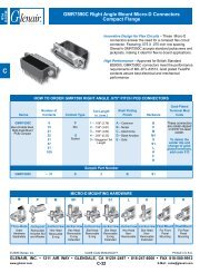
IntroIntroducing The Glenair<strong>Series</strong> <strong>28</strong> <strong>HiPer</strong>-D ConnectorAThe Advanced D-Sub Connector for ReliablePerformance in Hostile EnvironmentsProduct FeaturesD• Environmental, crimp removable rectangular connector• Advanced temperature, vibration <strong>and</strong> EMC/electrical performancermance• M24308/D-Sub intermateable• Fits panel <strong>and</strong> PCB footprint of M24308/D-Sub products• Available in all 11 “st<strong>and</strong>ard” insert arrangements• St<strong>and</strong>ard Density (#20) <strong>and</strong> High Density (#22D)• EMI spring• High temperature thermoset epoxy insulators• Watertight sealing• Rugged machined one-piece shell• Optional guide pins for blind matingAvailable configurations• Crimp termination for attaching wire or cable: St<strong>and</strong>ard cable, rear panel mount <strong>and</strong>float mount• Printed circuit board termination for rear panel mounting: Straight <strong>and</strong> right angle• Free-st<strong>and</strong>ing printed circuit board termination: Straight <strong>and</strong> right angleSealingCompoundBeCu ContactRetention ClipSize 20HD or 22DM39029 Pin ContactEMI SpringSize 20HD or 22DM39029 Socket ContactBeCu ContactRetention ClipBeCu InsertRetention ClipSealingCompoundFluorosiliconeGrommetBeCu InsertRetention ClipHigh TemperatureThermoset EpoxyFront <strong>and</strong> Rear insulatorFluorosiliconeinterfacial SealMachinedAluminum orStainless SteelShellHigh TemperatureThermoset EpoxyFront <strong>and</strong> Rear insulatorFluorosiliconeGrommetDimensions in inches (millimeters) <strong>and</strong> are subject to change without notice.© 2011 Glenair, Inc. CAGE Code 06324 Printed in U.S.A.GLENAIR, INC. • 1211 AIR WAY • GLENDALE, CA 91201-2497 • 818-247-6000 • FAX 818-500-9912www.glenair.com A-2 E-Mail: sales@glenair.com
<strong>Series</strong> <strong>28</strong> <strong>HiPer</strong>-DProduct Selection GuideIntro<strong>HiPer</strong>-D Connector Selection Guide<strong>Connectors</strong>with Pin ContactsACrimp TerminationFor Attaching Wire or CablePrinted Circuit BoardFor Rear Panel MountingPrinted Circuit BoardFree-St<strong>and</strong>ingSt<strong>and</strong>ardCableRear PanelMountFloatMountStraightPCBRightAngle PCBStraightPCBRightAngle PCB<strong>28</strong>0-018P <strong>28</strong>0-020P <strong>28</strong>0-030P <strong>28</strong>0-022P <strong>28</strong>0-024P <strong>28</strong>0-026P <strong>28</strong>0-0<strong>28</strong>PPage D-1 Page E-1 Page E-4 Page F-1 Page G-1 Page F-4 Page G-4D<strong>Connectors</strong> with SocketContactsCrimp TerminationFor Attaching Wire or CablePrinted Circuit BoardFor Rear Panel MountingPrinted Circuit BoardFree-St<strong>and</strong>ingSt<strong>and</strong>ardCableRear PanelMountFloatMountStraightPCBRightAngle PCBStraightPCBRightAngle PCB<strong>28</strong>0-019S <strong>28</strong>0-021S <strong>28</strong>0-031S <strong>28</strong>0-023S <strong>28</strong>0-025S <strong>28</strong>0-027S <strong>28</strong>0-029SPage D-3 Page E-7 Page E-10 Page F-11 Page G-11 Page F-14 Page G-14Dimensions in inches (millimeters) <strong>and</strong> are subject to change without notice.© 2011 Glenair, Inc. CAGE Code 06324 Printed in U.S.A.GLENAIR, INC. • 1211 AIR WAY • GLENDALE, CA 91201-2497 • 818-247-6000 • FAX 818-500-9912www.glenair.com A-3 E-Mail: sales@glenair.com
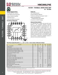
SERIES <strong>28</strong><strong>HiPer</strong>-DINSERT ARRANGEMENTS • SPECIFICATIONS • MOD CODESMIL-DTL-24308 D-Subminiature connectors are a popular choice for space flight. Their small size <strong>and</strong> reducedweight has led to their widespread use on space vehicles. The Glenair <strong>Series</strong> <strong>28</strong> <strong>HiPer</strong>-D connector bringsthe benefits of a crimp, rear-release contact system <strong>and</strong> superior performing machined shells, improved EMIshielding <strong>and</strong> robust resistance to vibration <strong>and</strong> shock to the st<strong>and</strong>ard D-Subminiature family. Specifying a <strong>Series</strong> <strong>28</strong><strong>HiPer</strong>-D connector for space flight may include NASA screening <strong>and</strong> outgassing processing (managed with simple modcodes) or material <strong>and</strong> plating selections such as the gold-plated <strong>HiPer</strong>-D connector shown above. See page B-2 for thecomplete range of material <strong>and</strong> plating options.GLENAIR, INC. • 1211 Air Way • Glendale, CA 91201-2497 www.glenair.com• Tel: 818-247-6000 • Email: sales@glenair.com • www.glenair.com
<strong>Series</strong> <strong>28</strong> <strong>HiPer</strong>-DGeneral information <strong>and</strong> ReferenceContact Arrangements, Product SpecificationsGeneralInformation <strong>HiPer</strong>-DHIPER-D CONTACT ARRANGEMENTS: STANDARD DENSITY, #20 CONTACTS1 56 91S99 #20 Contacts18 1 139 1514 252S1515 #20 Contacts3S2525 #20 Contacts1 1920 374S3737 #20 ContactsMating face of pinconnector.1 1718 3334 505S5050 #20 ContactsHIPER-D CONTACT ARRANGEMENTS: HIGH DENSITY, #22D CONTACTSB1 51 9611 1010 1815 19 261H1515 #22D Contacts1 2122 4243 624H6262 #22D Contacts2H2626 #22D Contacts121 39 2040 5960 785H7878 #22D Contacts1 15163031 443H4444 #22D Contacts1 2122 4243 6364 8485 1046H104104 #22D ContactsD1 2122 4243 624H6262 #22D Contacts121 39 2040 5960 785H7878 #22D Contacts1 2122 4243 6364 8485 1046H104104 #22D ContactsSPECIFICATIONSCurrent Rating#22D 5 AMPS, #20 7.5 AMPSTest Voltage1000 VAC RMSInsulation Resistance 5000 megohms minimumOperating Temperature -65° C. to +200° C.Ingress Protection IP 67Shock 300 g.Vibration, R<strong>and</strong>om 43.92 g.MATERIALS AND FINISHESShellAluminum alloyContactsCopper alloy, 50 microinches goldplated, stainless steel hoodInsulatorsThermoset epoxyRetention Clips Beryllium copper alloyGrommet, interfacialSealFluorosilicone rubberHardware300 series stainless steelDimensions in inches (millimeters) <strong>and</strong> are subject to change without notice.© 2011 Glenair, Inc. CAGE Code 06324 Printed in U.S.A.GLENAIR, INC. • 1211 AIR WAY • GLENDALE, CA 91201-2497 • 818-247-6000 • FAX 818-500-9912www.glenair.com B-1 E-Mail: sales@glenair.com
GeneralInformation<strong>Series</strong> <strong>28</strong> <strong>HiPer</strong>-DGeneral information <strong>and</strong> ReferenceShell Material <strong>and</strong> Finish OptionsAbout <strong>Series</strong> <strong>28</strong> <strong>HiPer</strong>-D Shell Material <strong>and</strong> Finish Options<strong>HiPer</strong>-D connector shells are made of aluminum alloy <strong>and</strong> are coated to improvecorrosion resistance. The United States Department of Defense (DOD) has m<strong>and</strong>ated theelimination of cadmium from DOD weapons systems because of toxicity concerns. TheEuropean Union has also restricted the use of cadmium on electronics equipment (RoHS).BGlenair’s 1000 Hour Grey nickel-PTFE plating (Code MT) meets the need for a highperformancecadmium replacement with excellent corrosion resistance, durability <strong>and</strong>excellent conductivity. In this catalog you will find four st<strong>and</strong>ard shell coatings: electrolessnickel, yellow chromate over cadmium, nickel-PTFE <strong>and</strong> black zinc-nickel. The tables belowshow additional options that are also available on any <strong>Series</strong> <strong>28</strong> <strong>HiPer</strong>-D connector.Shell PlatingPlatingCodeHIPER-D ALUMINUM SHELL PLATING CODESSaltFog Cadmium(Hours) FreeHexavalentChromiumFree Conductivity Typical ApplicationsDElectrolessNickelME 96 Yes Yes ExcellentNickel-PTFE MT 500 Yes Yes ExcellentSpace vehicles, missiles, avionics,unmanned vehicles, instrumentation.Harsh environment, soldier systems,communications equipment. Correspondsto MIL-DTL-24308 Code T.Zinc-Nickel withBlack ChromateZR 500 Yes Yes GoodHarsh environment, soldier systems.Corresponds to MIL-DTL-24308 Code K.Cadmium, Olive-DrabNF 500 No No Excellent Harsh environment, military equipment.Cadmium withYellow ChromateJF 500 No No ExcellentGeneral purpose military equipment.Comparable to MIL-DTL-24308 Code F.Black Anodize C 336 Yes YesNon-ConductiveApplications where EMI shielding is notrequired.Gold Z2 48 Yes Yes Excellent SpaceChem Film E 48 Yes No Excellent AvionicsShell PlatingPlatingCodeHIPER-D STAINLESS STEEL SHELL PLATING CODESSaltFog Cadmium(Hours) FreeHexavalentChromiumFree Conductivity Typical ApplicationsElectrolessNickelZM 500 Yes Yes ExcellentExtreme environments where stainless steelis preferred for strength, corrosion resistance.Passivated Z1 500 Yes Yes GoodExtreme environments where stainless steelis preferred for strength, corrosion resistance.Dimensions in inches (millimeters) <strong>and</strong> are subject to change without notice.© 2011 Glenair, Inc. CAGE Code 06324 Printed in U.S.A.GLENAIR, INC. • 1211 AIR WAY • GLENDALE, CA 91201-2497 • 818-247-6000 • FAX 818-500-9912www.glenair.com B-2 E-Mail: sales@glenair.com
<strong>Series</strong> <strong>28</strong> <strong>HiPer</strong>-DGeneral information <strong>and</strong> ReferenceProduct SpecificationsGeneralInformation <strong>HiPer</strong>-DDESCRIPTION REQUIREMENT PROCEDUREELECTRICALContact resistanceSAE AS39029 Table VMaxWire Test VoltageSize Current Drop20 7.5 5522 5 7324 3 4526 2 52<strong>28</strong> 1.5 54EIA-364-06IEC 60512-2-1Test current in amperes. Voltage dropin milli-volts. Silver-coated copper wire,+25°C.BLow Level Contact Resistance Wire Max.Size Milliohms20 922 1524 2026 31<strong>28</strong> 50EIA-364-23100 milliamperes maximum <strong>and</strong> 20 millivoltsmaximum open circuit voltageInsulation Resistance 5000 meg-ohms minimum EIA-364-21IEC-60512-3-1500 volts DC ± 50 volts. Test betweenadjacent contacts <strong>and</strong> contacts to shell.DDielectric withst<strong>and</strong>ing voltage No breakdown or fl ashover EIA-364-20IEC-60512-4-1Sea level AC RMS 50 or 60 Hz. Oneminute dwell.1000 voltsCurrent carrying capacity Contact MaxSize Current20 7.522 5EIA-364-70 Method 1IEC-60512-5 Test 9bShell-to-shell resistance (connectors withground springs)2.5 milli-volt drop maximum EIA-364-83IEC-60512-2-6Electroless nickel plated connectors.Shielding Effectiveness Frequency MinGHz Attenuation (dB)0.1 1000.4 900.8 851.0 803.0 556.0 4010.0 30EIA-364-66IEC-60512-23-3Pin Connector with Optional GroundingSpring, Electroless nickel plated shellsWater ImmersionMECHANICALNo evidence of water penetration intomated connectors. No evidence of waterpenetration into an unmated panelmounted PCB receptacle. ≥ 100 MΩinsulation resistance.MIL-STD-810F Method 512.41 meter immersion1 hourDimensions in inches (millimeters) <strong>and</strong> are subject to change without notice.© 2011 Glenair, Inc. CAGE Code 06324 Printed in U.S.A.GLENAIR, INC. • 1211 AIR WAY • GLENDALE, CA 91201-2497 • 818-247-6000 • FAX 818-500-9912www.glenair.com B-3 E-Mail: sales@glenair.com
GeneralInformation<strong>Series</strong> <strong>28</strong> <strong>HiPer</strong>-DGeneral information <strong>and</strong> ReferenceProduct SpecificationsDESCRIPTION REQUIREMENT PROCEDUREAir PressureNo detectable moisture. ≥ 100 MΩinsulation resistance.IEC-60512-7 Test 14b0.4 bar overpressure48 hours immersion at a depth of 150mmin 25° C tap water.BIngress Protection IP67 rating IEC-60529Vibration, Sine No discontinuity of greater than 1microseconds, no cracking, breaking orloosening of parts, plug shall not becomedisengaged from receptacle. <strong>Connectors</strong>shall meet electrical requirements aftervibration test.EIA-364-<strong>28</strong> Test Condition IVIEC-60512-6-4100 milliamp test current254 mm/sec from 10-50 Hz; 1.5 mmdouble amplitude from 50-140 Hz, <strong>and</strong> 60G from 140-2,000 HzDVibration, R<strong>and</strong>om No discontinuity of greater than 1microseconds, no cracking, breaking orloosening of parts, plug shall not becomedisengaged from receptacle. <strong>Connectors</strong>shall meet electrical requirements aftervibration test.Mechanical Shock No discontinuity of greater than 1microsecond, no cracking, breaking orloosening of parts, plug shall not becomedisengaged from receptacle. <strong>Connectors</strong>shall meet electrical requirements aftershock test.EIA-364-<strong>28</strong> Test Condition VI Letter JIEC-60512-6-4100 milliamp test current50- 2,000 Hz43.92 g. RMSEIA-364-27 Condition DIEC-60512-6-33 shocks X 3 axes X 2 directions = 18shocks 2941 m/s 2 (300 g’s), 3 ms, halfsineThermal ShockHumidity, Cyclic (Damp Heat, Cyclic)(Moisture Resistance)21 Day Humidity (Damp heat, LongTerm)Mechanical Durability, at AmbientTemperatureNo mechanical damage or looseningof parts. Following thermal shock,connector shall meet contact resistance,DWV, Insulation resistance <strong>and</strong> shell-toshellresistance requirements.No deterioration which will adverselyaffect the connector. 100 meg-ohmsminimum insulation resistance duringthe fi nal cycle. Following the recoveryperiod, connectors shall meet contactresistance, shell-to-shell resistance <strong>and</strong>DWV requirements.No deterioration which will adverselyaffect the connector. Following the dryingperiod, connectors shall meet 100 megohmsminimum, contact resistance,shell-to-shell resistance, DWV, mating<strong>and</strong> un-mating requirements.No deterioration which will adverselyaffect the connector after 2000 cyclesof mating <strong>and</strong> un-mating. <strong>Connectors</strong>shall meet contact resistance, insulationresistance, shell-to-shell resistance,DWV, <strong>and</strong> mating <strong>and</strong> un-mating force.EIA-364-32 Test Condition IVIEC-60512-11-45 cycles consisting of -65° C 30 minutes,+25° C 5 minutes max., + 200° C 30minutes, +25° C 5 minutes max.EIA-364-31 Condition B Method IIIIEC-60512-11-1<strong>28</strong>0-98% RH10 cycles (10 days)+25° C to +65° CStep 7b vibration deleted.24 hour recovery period.EIA-364-31 Condition C Method IIIEC-60512-11-3 Severity C90-95% RH40° CApply 100 volts DC during test. 4 hoursdrying time at ambient temperature priorto fi nal measurements.EIA-364-09IEC-60512-5 Test 9aDimensions in inches (millimeters) <strong>and</strong> are subject to change without notice.© 2011 Glenair, Inc. CAGE Code 06324 Printed in U.S.A.GLENAIR, INC. • 1211 AIR WAY • GLENDALE, CA 91201-2497 • 818-247-6000 • FAX 818-500-9912www.glenair.com B-4 E-Mail: sales@glenair.com
<strong>Series</strong> <strong>28</strong> <strong>HiPer</strong>-DGeneral information <strong>and</strong> ReferenceProduct SpecificationsGeneralInformation <strong>HiPer</strong>-DDESCRIPTION REQUIREMENT PROCEDURECorrosion (Salt Mist)Solderability, PC Tail ContactsNo exposure of base metal. <strong>Connectors</strong>shall meet DWV <strong>and</strong> contact resistancerequirements following the test.95% solder coverage. Smooth, bright<strong>and</strong> even fi nish.EIA-364-26IEC 60512-11-65% salt solution35° CUnmated connectorsCode M: Electroless nickel 48 hoursCode MT: Nickel-PTFE 500 hoursCode JF: Cadmium 500 HoursEIA-364-52 Category 3IEC-60512-12-1IEC-68-2-20 Test Ta, method 18 hours steam aging prior to test245° C 4-5 sec. dwell 10X magnifi cationBResistance To Soldering HeatNo damage to connector. <strong>Connectors</strong>shall meet insulation resistance <strong>and</strong>waterproof sealing requirements.EIA-364-56IEC-60512-12-5 Test 12e260° C, 10 seconds (PC tail)Impact, Cable <strong>Connectors</strong>No impairment of function. <strong>Connectors</strong>hall meet contact resistance, insulationresistance <strong>and</strong> waterproof sealing.EIA-364-42IEC-60512-5 test 7b1 meter, 8 dropsDFluid ImmersionNo damage from immersion in variousfuels <strong>and</strong> oils. Connector shall meetmating/un-mating force <strong>and</strong> dielectricwithst<strong>and</strong>ing voltage.EIA-364-10Altitude ImmersionNo evidence of moisture on connectorinterface or contacts. Connector shallmeet dielectric withst<strong>and</strong>ing voltage.EIA-364-03Contact Retention Contact Min. Min.Size Pounds Newtons22 9 4020 9 40Contact Separation Force Contact Min. Min.Size Ounces Newtons22 0.5 0.1420 0.7 0.19Mating <strong>and</strong> Un-mating Force Shell Min. Max.Size Unmating Mating1 0.75 10.02 1.00 17.03 1.75 <strong>28</strong>.04 2.50 39.05 3.25 49.06 4.50 65.0EIA-364-29.012 inch maximum displacement, bothaxial directionsSAE AS39029EIA-364-13Full complement of contacts1 to 10 inches per minute travel rateResidual Magnetism 2 μ maximum. EIA-364-54Insert RetentionNo dislocation of inserts from theiroriginal positions when subjected to anaxial load of 60 pounds per square inchEIA-364-35Apply force at a rate of 10 pounds persquare inch per second until specifi edpressure is reached.Dimensions in inches (millimeters) <strong>and</strong> are subject to change without notice.© 2011 Glenair, Inc. CAGE Code 06324 Printed in U.S.A.GLENAIR, INC. • 1211 AIR WAY • GLENDALE, CA 91201-2497 • 818-247-6000 • FAX 818-500-9912www.glenair.com B-5 E-Mail: sales@glenair.com
GeneralInformation<strong>Series</strong> <strong>28</strong> <strong>HiPer</strong>-DGeneral information <strong>and</strong> Reference<strong>HiPer</strong>-D <strong>Connectors</strong> for Space Flight<strong>Series</strong> <strong>28</strong> <strong>HiPer</strong>-D <strong>Connectors</strong> for Space FlightBDHOW TO ORDER SPACE GRADE HIPER-D CONNECTORSStep 1: Find a St<strong>and</strong>ard Part NumberSpace-grade <strong>HiPer</strong>-D connectors are available with electroless nickel (code ME)or with optional gold plated connector shells (code Z2). Other shell platings arenot recommended for space applications. NASA prohibits the use of cadmium inspace applications.Step 2: Select a NASA Screening LevelThe term “Screening Level” refers to the fi nal inspection procedure.Level 1 for mission-critical highest reliabilityLevel 2 for high reliabilityLevel 3 for st<strong>and</strong>ard reliabilityStep 3: Choose Outgassing ProcessingSt<strong>and</strong>ard <strong>HiPer</strong>-D connectors do not meet NASA outgassing requirements unlessthe connectors are specially processed. Testing has shown an oven bakeout for8 hours at +400°F is suffi cient to meet NASA requirements; however, a moreexpensive thermal vacuum outgassing process is also available. To specifyoutgassing processing, select the desired modifi cation code from the table below.Step 4: Select the Mod 429 Code that Matches the DesiredLevel of Screening <strong>and</strong> OutgassingUse the following table to choose the right modifi cation code. Add the mod code tothe connector part number. Example: <strong>28</strong>0-018P4S37MEGP-429CNASAScreeningLevelLevel 1 HighestReliabilityLevel 2 HighReliabilityLevel 3 St<strong>and</strong>ardReliabilityNASA SCREENING LEVELS AND MODIFICATION CODESSpecial Screening OnlyGrommet <strong>and</strong>Face SealinstalledGrommet <strong>and</strong>Face SealDeleted<strong>HiPer</strong>-D connectors feature space-grade materials, finishes <strong>and</strong> performance.The one-piece aluminum shell provides low residual magnetism. The reargrommet eliminates the need to backpot wires. High strength stainless steellocking hardware replaces gold-plated M24308-type brass hardware. The EMIspring provides shielding protection. The resilient interfacial seal protectsmated connectors from dust, moisture <strong>and</strong> corrosion.Special Screening PlusOutgassing Processing8 HourOven Bake400° F.Thermal VacuumOutgassing24 hrs. 125° C.Mod 429B (1) Mod 429F (1) Mod 429J Mod 429CMod 429 (1) Mod 429D (1) Mod 429K Mod 429A(Use st<strong>and</strong>ardpart number)EEE-INST-002 requires outgassing for M24308.(1)Indicates no outgassing performedMod 432 (1) Mod 186 Mod 186MNASA screeningNASA specification EEE-INST-002 providesinstructions on selecting, screening <strong>and</strong>qualifying parts for use on NASA GSFCspace flight projects. Table 2B in the NASAspecification contains inspection instructionsfor MIL-DTL-24308 D-type connectors.Table 2B applies by similarity to <strong>HiPer</strong>-Dconnectors, except for residual magnetismscreening. This table calls for 100% residualmagnetism screening, but the <strong>HiPer</strong>-Dconnector will not be 100% screened unlessspecial arrangements are made. EEE-INST-002 requires outgassing for M24308.(1)Indicates no outgassing performedNASA screening levelsNASA defines three levels of screening: level 1for highest reliability, level 2 for high reliability,<strong>and</strong> level 3 for st<strong>and</strong>ard reliability. Level 3equates to st<strong>and</strong>ard lot acceptance inspection.Levels 1 <strong>and</strong> 2 call for additional testing.Qualification requirementsProjects using connectors covered bymilitary specifi cations are typically able towaive qualifi cation testing. The <strong>Series</strong> <strong>28</strong><strong>HiPer</strong>-D connector is not covered by a militaryspecification. Projects considering usingthis connector for space flight should obtainguidance from the overseeing space agencyregarding the suitability of this connector <strong>and</strong>any testing that might be recommended.ASTM E595The space industry has adopted a st<strong>and</strong>ardizedtest procedure, ASTM E 595, to evaluateout-gassing properties of polymers. Smallsamples of material are heated to 125° C. ata vacuum of 5 X 10 -5 torr for 24 hours. Thenthe sample is weighed to calculate the TotalMass Loss (TML). The TML cannot exceed1.00% of the total initial mass. The quantity ofoutgassed matter is calculated to determinethe Collected Volatile Condensable MaterialDimensions in inches (millimeters) <strong>and</strong> are subject to change without notice.© 2011 Glenair, Inc. CAGE Code 06324 Printed in U.S.A.GLENAIR, INC. • 1211 AIR WAY • GLENDALE, CA 91201-2497 • 818-247-6000 • FAX 818-500-9912www.glenair.com B-6 E-Mail: sales@glenair.com
<strong>Series</strong> <strong>28</strong> <strong>HiPer</strong>-DGeneral information <strong>and</strong> Reference<strong>HiPer</strong>-D <strong>Connectors</strong> for Space FlightGeneralInformation <strong>HiPer</strong>-D<strong>Series</strong> <strong>28</strong> <strong>HiPer</strong>-D <strong>Connectors</strong> for Space Flight(CVCM). The CVCM cannot exceed 0.10% ofthe original specimen mass.Materials Approved for SpaceMetal materials such as aluminum alloyconnector shells, copper retention clips,gold-plated pin <strong>and</strong> socket contacts,stainless steel contact hoods <strong>and</strong> so on,are approved for space. Rigid non-metallicmaterials, such as LCP or epoxy insulators,<strong>and</strong> epoxy potting compounds are alsoapproved for space fl ight. Resilient nonmetallicmaterials, such as fl uorosiliconegrommets <strong>and</strong> interfacial seals, typicallyrequire outgassing processing, as do alladhesives.Residual MagnetismSt<strong>and</strong>ard aluminum shell <strong>HiPer</strong>-D connectorsare nonmagnetic. Spacecraft designersgenerally avoid the use of ferromagneticmaterials, which can become magnetized<strong>and</strong> can interfere with sensitive instruments.Although D type connectors typically are100% screened for residual magnetism,the aluminum shell <strong>HiPer</strong>-D connectorhas adopted the magnetic permeabilityrequirements for space-grade MIL-DTL-83513 <strong>and</strong> MIL-DTL-38999 connectors.These specifi cations require 2μ maximummagnetic permeability. This requirementis considered to be a qualification test <strong>and</strong>is not invoked as a screening test unlessspecifically requested.Cryogenic Exposure<strong>Series</strong> <strong>28</strong> <strong>HiPer</strong>-D connectors are ratedto -65° C. Glenair does not yet have datato validate these connectors for cryogenicapplications. EEE-INST-002 states“...experience has proven it is possible for(non-certifi ed) connector types to be usedsuccessfully at cryogenic temperatures. Itis recommended that connector samplesshould be subjected to fi ve cycles ofcryogenic temperature...(followed byexamination for cracks <strong>and</strong> DWV)”.TML <strong>and</strong> CVMLGlenair has conducted testing on allconnector materials to establish typicalpercentage material loss (TML) <strong>and</strong>collected volatile material loss (CVML).OutgassingPlastic <strong>and</strong> rubber materials give off gaseous molecules. For example, the smell inside a newcar is caused by polymer outgassing. Heat <strong>and</strong> vacuum increase the rate of diffusion. In aspacecraft the gases coming off polymers can contaminate optical surfaces <strong>and</strong> instruments.The result is degraded performance.Glenair recommends that <strong>HiPer</strong>-D connectors for space flight should be oven baked orthermal vacuum outgassed. The table below shows <strong>HiPer</strong>-D connector materials that must bepostcured or baked to meet outgassing limits. Components such as insulators <strong>and</strong> seals areroutinely postcured prior to connector assembly. However, some materials such as RTV canonly be outgassed once the connector is assembled. NASA states “A bakeout for outgassingcontrol is driven by the application <strong>and</strong> may be required where tight contamination controlmust be maintained.” This processing can be performed by Glenair; however, some customersprefer to fabricate higher level subassemblies before outgassing processing is performed.OUTGASSING PROPERTIES OF HIPER-D MATERIALSComponent Material Outgassing PropertyInsulator, PCB Trays Thermoset epoxy Meets ASTM E595Grommet <strong>and</strong> Face Seal Flourosilicone Postcure is requiredAdhesive Eccobond 104 A/B Meets ASTM E595Sealant DC3145 <strong>and</strong> DC3140 RTV Postcure is requiredEpoxy ink Markem 7224 Meets ASTM E595O-ring Fluorosilicone Postcure is requiredNASA EEE-INST-002 SCREENING REQUIREMENTSInspection/ Test NASA Level 1 NASA Level 2Visual inspection 100% 100%Mechanical 2 pcs. 2 pcs.Voltage (DWV) 2 pcs. 2 pcs.Insulation Resistance 2 pcs. 2 pcs.Mating <strong>and</strong> Unmating Force 2 pcs. N/AContact Engagement <strong>and</strong> Separation Force 2 pcs. N/ASolderability/Resistance to Soldering Heat 2 pcs. N/A1. NASA screening requirements from Table 2B of EEE-INST-002 Screening Requirements.OUTGASSING AT-A-GLANCE• Fluorosilicone rubber components used in <strong>HiPer</strong>-D connectors, such as o-rings,grommets <strong>and</strong> seals do not comply with NASA outgassing requirements.• NASA nevertheless recommends additional processing to reduce outgassing of allmaterials to minimal levels.• An inexpensive oven bakeout delivers excellent results compared to thermal vacuumoutgassing. The high temperature of the oven bakeout effectively removes volatilematerials.• Glenair 429 mod codes provide easy ordering, whichever outgassing option is required.Please consult factory for test reports.Dimensions in inches (millimeters) <strong>and</strong> are subject to change without notice.© 2011 Glenair, Inc. CAGE Code 06324 Printed in U.S.A.GLENAIR, INC. • 1211 AIR WAY • GLENDALE, CA 91201-2497 • 818-247-6000 • FAX 818-500-9912www.glenair.com B-7 E-Mail: sales@glenair.comBD
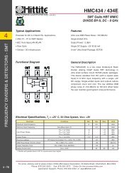
SERIES <strong>28</strong><strong>HiPer</strong>-DCONTACTS • ASSEMBLY TOOLS • BAND-MASTER ATS<strong>Series</strong> <strong>28</strong> <strong>HiPer</strong>-D connectors are supplied with loose crimp contacts, terminated to wires using mil spec crimp tools.The <strong>HiPer</strong>-D connector features crimp, rear-release st<strong>and</strong>ard size #20 <strong>and</strong> #22 gold-plated copper alloy contactsthat meet the requirements of SAE AS39029. Military Specification MIL-DTL-22520 provides the aerospace/defenseindustry with a common set of rugged, reliable h<strong>and</strong> crimp tools. This specification controls the voltage drop <strong>and</strong> tensilestrength of crimp terminations. The <strong>Series</strong> <strong>28</strong> <strong>HiPer</strong>-D family of products is well-supported with a complete range ofcontacts, tools <strong>and</strong> assembly instructions for turnkey assembly <strong>and</strong> use.GLENAIR, INC. • 1211 Air Way • Glendale, CA 91201-2497 • Tel: 818-247-6000 • Email: sales@glenair.com • www.glenair.com
<strong>Series</strong> <strong>28</strong> <strong>HiPer</strong>-DContacts <strong>and</strong> ToolsSelection Guide <strong>and</strong> General informationContacts<strong>and</strong> Tools#20 ContactsPage C-2#22D ContactsPage C-3Grommet Sealing PlugsPage C-4Insertion/Extraction ToolsPage C-4CContact Crimping ToolsPage C-4Positioners for Crimp ToolsPage C-4B<strong>and</strong>-Master ATS ShieldB<strong>and</strong> installation ToolPage C-5B<strong>and</strong>-Master ATS ShieldB<strong>and</strong>sPage C-5PinContactINSPECTION HOLECRIMP JOINTCRIMP BARRELSTAINLESS STEELHOODINSPECTION HOLECRIMP JOINTCRIMP BARRELSocketContactCONTACTRETENTION CLIPCOLOR BANDS (BIN CODE)COLOR BANDS (BIN CODE)CONTACTRETENTION CLIPAbout <strong>HiPer</strong>-D ContactsAbout Crimp ToolsThis section of the catalog containsordering information for contacts, crimptools <strong>and</strong> insertion/extraction tools.<strong>HiPer</strong>-D connectors are supplied withloose crimp contacts. Contacts areterminated to wire using crimp tools <strong>and</strong>are snapped into place by h<strong>and</strong> or witha h<strong>and</strong>-held insertion tool. Damaged ormiswired contacts may be removed fromthe connector using extraction tools.Although the connectors are suppliedwith a full complement of contacts, extracontacts are frequently purchased asspares or to use for quality assurancepurposes such as crimp tensile tests.<strong>HiPer</strong>-D contacts conform to therequirements of Aerospace St<strong>and</strong>ardAS39029. This SAE specification definesthe design, dimensions <strong>and</strong> performanceof contacts used in aerospace gradeelectrical connectors. The “generalspecification” covers a variety of contacts.The "slash sheets" contain dimensions<strong>and</strong> other information for specific types ofcontacts. Each contact is assigned a BasicIdentification Number (BIN), a three digitcode corresponding to the color codeon the contacts. A Qualified ProductsList (QPL) identifies those manufacturerswhose products have been verified tomeet all requirements.<strong>Series</strong> <strong>28</strong> contacts are crimped towire using mil spec crimpers. MilitarySpecification MIL-DTL-22520 providesthe aerospace/defense industry with acommon set of rugged, reliable h<strong>and</strong>crimp tools. This specification controls thevoltage drop <strong>and</strong> tensile strength of crimpterminations.Before ordering, check to see if you mightalready have these tools! We have listedthe military part number <strong>and</strong> the Danielspart number. Daniels ManufacturingCorporation is the leading manufacturerof mil spec crimp tools. Glenair stocks allthese tools for immediate delivery.Dimensions in inches (millimeters) <strong>and</strong> are subject to change without notice.© 2011 Glenair, Inc. CAGE Code 06324 Printed in U.S.A.GLENAIR, INC. • 1211 AIR WAY • GLENDALE, CA 91201-2497 • 818-247-6000 • FAX 818-500-9912www.glenair.com C-1 E-Mail: sales@glenair.com
Contacts<strong>and</strong> Tools<strong>Series</strong> <strong>28</strong> <strong>HiPer</strong>-DContacts <strong>and</strong> Tools#20 Crimp Contacts for St<strong>and</strong>ard Density Contact ArrangementsCSize #20 Crimp Contacts1Pin Contact2Socket ContactSt<strong>and</strong>ard size #20 contacts accept #20 to #24 AWG wire. These gold-plated copper alloy contactsmeet the requirements of SAE AS39029.1Pin contact. Fits <strong>HiPer</strong>-D pin connectors <strong>and</strong>M24308/4 connectors with st<strong>and</strong>ard densitycontact arrangements.ContactType Fig. Wire Size Part NumberM39029 PartNumberPin 1 #20-24 850-022-20-369 M39029/64-369Socket 2 #20-24 850-021-20-368 M39029/63-368.549 (13.94)2Socket contact. Fits <strong>HiPer</strong>-D socket connectors<strong>and</strong> M24308/2 connectors with st<strong>and</strong>ard densitycontact arrangements..194/.189(4.93/4.80).033/.029(0.84/0.74)WhiteBlueOrangeMaterial <strong>and</strong> FinishCopper alloy, 50 microinches gold plated perASTM B488 Type II Code C Class 1,27 overnickel plate per QQ-N-290 Class 2, 50-150microinches.Socket contact hood: 305 CRES, passivated.SpecificationsCurrent Rating: 7.5 Amps maximumVoltage Drop (at 7.5 Amps <strong>and</strong> 25° C, #20AWGsilver-plated wire):55 millivolts maximumTemperature Range: -65° to + 200° C.Socket Contact Minimum Separation Force0.7 ouncesSee SAE AS39029 for additional electrical,mechanical <strong>and</strong> environmental specifications.Crimp Tools <strong>and</strong> Insertion/Removal ToolsCrimper: 809-015 (M22520/2-01)Positioner: 859-016 (M22520/2-08)Insertion/Removal Tool: 859-017(M81969/39-01)WireGageCRIMP TENSILE STRENGTHAxial load in minimum pounds.Silver or TinCoated CopperWireNickelCoatedCopper Wire#20 20 19#22 12 8#24 8 6Ø .073/.069(1.85/1.75)Ø .073/.069(1.85/1.75)Ø .041/.039(1.04/0.99).325/.321(8.26/8.15).379 / .373(9.63/9.47).067(1.70).536 (13.61) REFØ.033/.025(0.84/0.64)Thru One Side Only.185/.150(4.70/3.81)Pin Contact.185/.150(4.70/3.81)GrayBlueSocket ContactOrange.033/.029(0.84/0.74).194/.189(4.93/4.80).049/.040(1.24/1.02)Ø .046/.043(1.16/1.09)ø .068/.065(1.73/1.65)Pin <strong>and</strong> Socket Crimp Barrel DimensionsØ .046/.043(1.16/1.09)Ø .085/.082(2.16/2.08)Ø(0.84/0.64).033/.025Thru One Side Onlyø .071/.068(1.80/1.73)Ø .085/.082(2.16/2.08)Dimensions in inches (millimeters) <strong>and</strong> are subject to change without notice.© 2011 Glenair, Inc. CAGE Code 06324 Printed in U.S.A.GLENAIR, INC. • 1211 AIR WAY • GLENDALE, CA 91201-2497 • 818-247-6000 • FAX 818-500-9912www.glenair.com C-2 E-Mail: sales@glenair.com
<strong>Series</strong> <strong>28</strong> <strong>HiPer</strong>-DContacts <strong>and</strong> Tools#22D Crimp Contacts for High Density Contact ArrangementsContacts<strong>and</strong> ToolsSize #22D Crimp ContactsWireGagePin ContactSocket ContactMaterial <strong>and</strong> FinishCopper alloy, 50 microinches gold plated perASTM B488 Type II Code C Class 1,27 overnickel plate per QQ-N-290 Class 2, 50-150microinches.Socket contact hood: 305 CRES, passivated.SpecificationsCurrent Rating: 5 Amps maximumContact Resistance (at 5 Amps <strong>and</strong> 25° C, #22AWG silver-plated wire):73 millivolt drop maximumTemperature Range: -65° to + 200° C.Socket Contact Minimum Separation Force0.7 ouncesSee SAE AS39029 for additional electrical,mechanical <strong>and</strong> environmental specifications.CRIMP TENSILE STRENGTHAxial load in minimum pounds.Silver or TinCoated CopperWire12NickelCoatedCopper Wire#22 12 8#24 8 6#26 5 3#<strong>28</strong> 3 2Size #22D contacts accept #22 to #<strong>28</strong> AWG wire. These gold-plated copper alloy contacts meet therequirements of SAE AS39029.1Pin contact. Fits <strong>HiPer</strong>-D pin connectors <strong>and</strong>M24308/4 connectors with high density contactarrangements.ContactTypeFig. Wire Size Part NumberM39029 PartNumberPin 1 #22-<strong>28</strong> 850-002-22-360 M39029/58-360Socket 2 #22-<strong>28</strong> 850-003-22-354 M39029/57-354Ø .0305/.0295(0.775/0.749).062 (1.57)ØMAXContactType2Pin ContactSocket ContactCRIMP TOOLS AND INSERTION/EXTRACTION TOOLCrimpPart Number Tool PositionerInsertion/Extraction ToolPin 850-002-22-360 809-015 859-018 859-020Socket 850-003-22-354 809-015 859-019 859-020Socket contact. Fits <strong>HiPer</strong>-D socket connectors<strong>and</strong> M24308/2 connectors with high densitycontact arrangements..531 (13.49) REF BLACK.300 / .295(7.62/7.49)BLUEØ .062/.060(1.57/1.52)ORANGEØ .022/.018(0.56/0.46)THRU ONE SIDE ONLY.518 (13.16) REF YELLOW.<strong>28</strong>9 / .279(7.34 / 7.09)GREENORANGEØ .022/.018(0.56/0.46)THRU ONE SIDE ONLY.141 (3.58)MIN.237 / .231(6.02 / 5.87).141 (3.58)MIN.237 / .231(6.02 / 5.87)Ø .0355/.0335(0.90/0.85)Ø .048/.046(1.22/1.17)Ø .0355/.0335(0.90/0.85)Ø .048/.046(1.22/1.17)CDimensions in inches (millimeters) <strong>and</strong> are subject to change without notice.© 2011 Glenair, Inc. CAGE Code 06324 Printed in U.S.A.GLENAIR, INC. • 1211 AIR WAY • GLENDALE, CA 91201-2497 • 818-247-6000 • FAX 818-500-9912www.glenair.com C-3 E-Mail: sales@glenair.com
Contacts<strong>and</strong> Tools<strong>Series</strong> <strong>28</strong> <strong>HiPer</strong>-DContacts <strong>and</strong> ToolsCrimp Tools, Insertion-Extraction Tools, Sealing PlugsMiniature Adjustable Crimp Tool <strong>and</strong> PositionersBACThese crimp tools perform precision eight indent crimps for gas-tight wire terminations <strong>and</strong> excellenttensile strength. Adjustment wheel has 8 settings. Ratchet mechanism prevents improper crimps. Usewith bayonet-type positioners, ordered separately. Check calibration with M22520/3 gages. Lengthis 6.75 inches, weight is approx. 10 oz.ASt<strong>and</strong>ard M22520/2-01 crimper. Use with size #22D<strong>and</strong> #20 <strong>HiPer</strong>-D contacts. Requires positioner,ordered separately.CPositioner for use with #22D pin contacts. Usewith contact 850-002-22-360 (M39029/58-360).BPositioner for use with st<strong>and</strong>ard #20 contacts.Use with contacts 850-022-20-369 (M39029/64-369) <strong>and</strong> 850-021-20-368 (M39029/63-368).DPositioner for use with #22D socket contacts. Usewith contact 850-003-22-354 (M39029/57-354).CDFigurePart NumberMilitary PartNumberA 809-015 M22520/2-01 AFM8B 859-016 M22520/2-08 K13-1C 859-018 M22520/2-09 K42D 859-019 M22520/2-06 K41Daniels PartNumber (1)(1) Daniels Manufacturing Corporation,Orl<strong>and</strong>o, Florida is the industryleadingsupplier of mil spec contacttermination tooling. In addition to thetools shown in this catalog, the Danielsproduct line includes a completerange of installation tools <strong>and</strong> semiautomaticequipment.Contact Insertion n <strong>and</strong> Removal Tools121Insertion/Extraction Tool for #20HD contacts.This plastic tool features green insertion tip<strong>and</strong> white extraction tip.2Figure Size Type Part NumberInsertion/Extraction Tool for #22D contacts.This plastic tool features green insertion tip<strong>and</strong> white extraction tip.Military PartNumberDaniels PartNumber1 #20HD Insertion/Extraction 859-017 M81969/39-01 M81969/39-012 #22D Insertion/Extraction 859-020 M81969/14-01 M81969/14-01Grommet Sealing Plugs12Grommet sealing plugs are used to seal unwired contact cavities. These plugs conform to MS27488requirements. After installing unwired contacts into unused cavities, insert knob end of sealing pluginto grommet until it bottoms against the unwired contact per illustration. Install sealing plugs withst<strong>and</strong>ard contact insertion/extraction tools .BØ CFig. Size ColorPartNumberMilitary PartNumberØ AInsertion/Removal ToolA Ref. B Ref. C Ref. D Ref.in. mm in. mm in. mm in. mm1 #22 Black 859-021 MS27488-22-2 M81969/14-01 .042 1.07 .51 13.0 .062 1.57 .125 3.182 #20 Red 859-012 MS27488-20-2 M81969/39-01 .053 1.35 .82 20.8 .085 2.16 .125 3.18Here's e' a Tip!installation of Sealing Plugs“When installing sealing plug in connector cavities without contacts,the end opposite the knob shall be inserted first <strong>and</strong> the knob shallbe seated against the grommet face. When installing into cavitieswith contacts, the sealing plugs shall be installed knob end first <strong>and</strong>shall bottom on the contact wire barrel.”(NAVAIR 01-1A-505–1 installation manual)SEALINGPLUGDimensions in inches (millimeters) <strong>and</strong> are subject to change without notice.© 2011 Glenair, Inc. CAGE Code 06324 Printed in U.S.A.GLENAIR, INC. • 1211 AIR WAY • GLENDALE, CA 91201-2497 • 818-247-6000 • FAX 818-500-9912www.glenair.com C-4 E-Mail: sales@glenair.comDUNWIREDCONTACT
<strong>Series</strong> <strong>28</strong> <strong>HiPer</strong>-DContacts <strong>and</strong> ToolsB<strong>and</strong>-Master Advanced Termination SystemB<strong>and</strong>s <strong>and</strong> instructionsContacts<strong>and</strong> ToolsGlenair B<strong>and</strong>-Master Advanced Termination System (ATS): How To Order1Fast, cost-effective shield termination. Attach cable shields to backshells with B<strong>and</strong>-Master ATS stainlesssteel straps. The B<strong>and</strong>-Master ATS system offers fast termination <strong>and</strong> the flexibility to h<strong>and</strong>le a wide rangeof parts with just one b<strong>and</strong> size. Approved for aerospace <strong>and</strong> defense, these straps have successfully passedrigorous shock, vibration <strong>and</strong> environmental testing.1B<strong>and</strong> installation Tool. Use with .240" (6.10 mm)wide b<strong>and</strong>s. 6.75 inches (172 mm) length, 1.2pounds (0.6 Kg.)2St<strong>and</strong>ard B<strong>and</strong>, .240" (6.10 mm) wide. Availablein two lengths, flat or pre-coiled. Stainless steel.Figure Description Part Number1 B<strong>and</strong> installation Tool 600-0582Length Part Number Accommodates DiameterFigure in. mm Flat Pre-Coiled in. mm2 14.250 362.1 600-052 600-052-1 1.8 45.72 18.000 457.2 600-090 600-090-1 2.5 63.5Contact Glenair or visit our website (glenair.com) to view our complete line of B<strong>and</strong>-Master ATS products,including pneumatic tools for high volume production <strong>and</strong> calibration kits.LENGTH ± .060 (1.5).240 (6.10)C1. Prepare Cable Braid for ter mi na tion pro cess(Figure 1).2. Push Braid forward over Adapter Re ten tion Lipto the Adapter incline Point (or .4" [10.2mm]minimum braid length). Milk Braid as re quiredto remove slack <strong>and</strong> insure a snug fit aroundthe shield ter mi na tion area (Fig ure 2).3. Prepare the B<strong>and</strong> in the fol low ing manner:IMPORTANT: Due to Con nec tor/Adapt er circumfer ence, it may be necessary to preparethe B<strong>and</strong> around the Cable or Retention Area.A. Roll B<strong>and</strong> through the Buckle Slot twice.(B<strong>and</strong>s must be double-coiled.)B. Pull on B<strong>and</strong> until Mark ( ) is within approxi mate ly .250 inch (6.4mm) of Buck leSlot (Figure 3). The B<strong>and</strong> may be tightenedfurther if desired.NOTE: Prepared B<strong>and</strong> should have ( ) Markvisible ap prox i mate ly where shown in Figure 3..350 (8.9)B<strong>and</strong>-Master ATS Shield Termination instructionsShield TerminationClamping Process (Figures 4 thru 8)NOTE: To free Tool Han dles, move Hold ing Clipsto center of Tool.4. Squeeze Gripper Release Lever <strong>and</strong> insertB<strong>and</strong> into the front end opening of the Tool.(NOTE: Cir cu lar portion of looped b<strong>and</strong> mustalways face down ward.)5. Aligning the B<strong>and</strong> <strong>and</strong> Tool with the ShieldTermination Area, squeeze Black Pull-UpH<strong>and</strong>le repeatedly using short strokes untilit locks against Tool Body. (This in di cates theB<strong>and</strong> is compressed to the Tool PrecalibratedTension.)NOTE: If alignment of b<strong>and</strong> <strong>and</strong> shield is unsatis fac to ry, tension on b<strong>and</strong> can be relaxedby push ing on slotted release lever on topof tool. Make ad just ments as nec es sary <strong>and</strong>again squeeze black pull-up h<strong>and</strong>le.6. Complete the Clamping Process by squeezingthe Gray Cut-Off Han dle.7. Remove excess b<strong>and</strong> from tool <strong>and</strong> dispose.8. inspect Shield Termination.1357AdapterRetention LipConductorsBraidAdapterincline 2BuckleTAIL LENGTHINDICATOR MARKTail Lengthindicator Mark468.400 (1.2mm) Min.Length Braid OverTermination AreaDimensions in inches (millimeters) <strong>and</strong> are subject to change without notice.© 2011 Glenair, Inc. CAGE Code 06324 Printed in U.S.A.GLENAIR, INC. • 1211 AIR WAY • GLENDALE, CA 91201-2497 • 818-247-6000 • FAX 818-500-9912www.glenair.com C-5 E-Mail: sales@glenair.com
SERIES <strong>28</strong><strong>HiPer</strong>-DSECTIONS D, E, F AND G CONNECTOR SELECTION GUIDE<strong>Connectors</strong>with Pin ContactsCrimp TerminationFor Attaching Wire or CablePrinted Circuit BoardFor Rear Panel MountingPrinted Circuit BoardFree-St<strong>and</strong>ingSt<strong>and</strong>ardCableRear PanelMountFloatMountStraightPCBRightAngle PCBStraightPCBRightAngle PCB<strong>28</strong>0-018P <strong>28</strong>0-020P <strong>28</strong>0-030P <strong>28</strong>0-022P <strong>28</strong>0-024P <strong>28</strong>0-026P <strong>28</strong>0-0<strong>28</strong>PPage D-1 Page E-1 Page E-4 Page F-1 Page G-1 Page F-4 Page G-4<strong>Connectors</strong> with SocketContactsCrimp TerminationFor Attaching Wire or CablePrinted Circuit BoardFor Rear Panel MountingPrinted Circuit BoardFree-St<strong>and</strong>ingSt<strong>and</strong>ardCableRear PanelMountFloatMountStraightPCBRightAngle PCBStraightPCBRightAngle PCB<strong>28</strong>0-019S <strong>28</strong>0-021S <strong>28</strong>0-031S <strong>28</strong>0-023S <strong>28</strong>0-025S <strong>28</strong>0-027S <strong>28</strong>0-029SPage D-3 Page E-7 Page E-10 Page F-11 Page G-11 Page F-14 Page G-14GLENAIR, INC. • 1211 Air Way • Glendale, CA 91201-2497 www.glenair.com• Tel: 818-247-6000 • Email: sales@glenair.com • www.glenair.com
<strong>28</strong>0-018P<strong>Series</strong> <strong>28</strong> <strong>HiPer</strong>-D Pin <strong>Connectors</strong>for Cable TerminationCable<strong>Connectors</strong><strong>HiPer</strong>-D Pin <strong>Connectors</strong> with Crimp Contacts<strong>HiPer</strong>-D pin connectors feature crimp, rear-releaseable size #20 or #22D contacts.Intermateable with st<strong>and</strong>ard M24308-type D-Subminiature connectors, the <strong>HiPer</strong>-Dfeatures a rugged machined aluminum shell, waterproof sealing <strong>and</strong> optional groundsprings for improved resistance to electromagnetic interference. Gold-plated size #20contacts conform to M39029/64-369 <strong>and</strong> accept #20 to #24 AWG wire. Gold-platedsize #22D contacts conform to M39029/58-360 <strong>and</strong> accept #22 to #<strong>28</strong> AWG wire.Contacts are packaged with connector. Terminate contacts with crimp tools purchasedseparately. Glass-reinforced thermoset epoxy insulators, copper alloy retention clips.Fluorosilicone face seal <strong>and</strong> rear grommet meet IP67 immersion requirement. 1000VAC, 5 Amps (#22D) or 7.5 Amps (#20).HOW TO ORDERSample Part Number<strong>28</strong>0-018P 1S9 ME G SPart NumberShell Size -Insert Arr. Shell Material/Finish EMI Spring Hardware OptionD<strong>28</strong>0-018P<strong>HiPer</strong>-D CableConnector With PinContactsSt<strong>and</strong>ard Density#20 ContactsContactLayout Quantity1S9 92S15 153S25 254S37 375S50 50High Density#22D ContactsContactLayout Quantity1H15 152H26 263H44 444H62 625H78 786H104 104MEAluminum withElectroless NickelFinishgeneral purposeapplications, excellentconductivityMTAluminum with Nickel-PTFE Finish1000 Hour Greymaximum corrosionprotection,durability, <strong>and</strong>excellent conductivity(non-refl ective grey)JFAluminum withCadmium, YellowChromatefor severe environments,excellent conductivitySPECIFICATIONSCurrent Rating#22D 5 AMPS, #20 7.5 AMPSTest Voltage1000 VAC RMSInsulation Resistance 5000 megohms minimumOperating Temperature -65° C. to +200° C.Ingress Protection IP 67Shock 300 g.Vibration, R<strong>and</strong>om 43.92 g.GEMI SpringNNo SpringNThru-HoleNo HardwareLLow-Profi le CaptivatedJackscrew, Hex HeadSLow-Profi le CaptivatedJackpost, Hex HeadPFemale JackpostKSlot-Head ExtendedJackscrewTSlot-Head ExtendedCaptivated JackpostMATERIALS AND FINISHESShellAluminum alloyContactsCopper alloy, 50 microinches goldplatedInsulatorsThermoset epoxyRetention Clips Beryllium copper alloyGrommet <strong>and</strong> Seal Fluorosilicone rubberHardware300 series stainless steelDimensions in inches (millimeters) <strong>and</strong> are subject to change without notice.© 2011 Glenair, Inc. CAGE Code 06324 Printed in U.S.A.GLENAIR, INC. • 1211 AIR WAY • GLENDALE, CA 91201-2497 • 818-247-6000 • FAX 818-500-9912www.glenair.com D-1 E-Mail: sales@glenair.com
Cable<strong>Connectors</strong><strong>28</strong>0-018P<strong>Series</strong> <strong>28</strong> <strong>HiPer</strong>-D Pin <strong>Connectors</strong>for Cable TerminationHIPER-D CONTACT ARRANGEMENTS: STANDARD DENSITY, #20 CONTACTS1 56 91S99 #20 Contacts18 1 139 1514 252S1515 #20 Contacts3S2525 #20 Contacts1 1920 374S3737 #20 ContactsMating face of pinconnector.1 1718 3334 505S5050 #20 ContactsHIPER-D CONTACT ARRANGEMENTS: HIGH DENSITY, #22D CONTACTSD1 51 9611 1010 1815 19 261H1515 #22D Contacts1 2122 4243 624H6262 #22D Contacts2H2626 #22D Contacts121 39 2040 5960 785H7878 #22D ContactsMating face of pin connector.1 15163031 443H4444 #22D Contacts1 2122 4243 6364 8485 1046H104104 #22D ContactsREF .134(3.40) RACDØ .120 (3.05)TYP.049(1.24).435(11.05)FB E GOPTIONAL GROUNDSPRING 2 PLCS10°TYP.262 ± .005(6.65 ± 0.13)BACKSHELLMOUNTINGGROOVE10°TYPShellSizein± .015<strong>28</strong>0-018P DIMENSIONSA B C Basic D E F Max. G Max.mm± 0.38in± .015mm± 0.38 in. mmin± .005Dimensions in inches (millimeters) <strong>and</strong> are subject to change without notice.© 2011 Glenair, Inc. CAGE Code 06324 Printed in U.S.A.GLENAIR, INC. • 1211 AIR WAY • GLENDALE, CA 91201-2497 • 818-247-6000 • FAX 818-500-9912www.glenair.com D-2 E-Mail: sales@glenair.commm± 0.13in± .005mm± 0.13 in. mm in. mm1 1.213 30.81 .494 12.55 .984 24.99 .726 18.44 .389 9.88 .769 19.53 .432 10.972 1.541 39.14 .494 12.55 1.312 33.32 1.054 26.77 .389 9.88 1.093 27.76 .432 10.973 2.088 53.04 .494 12.55 1.852 47.04 1.594 40.49 .389 9.88 1.635 41.53 .432 10.974 2.729 69.32 .494 12.55 2.500 63.50 2.242 56.95 .389 9.88 2.<strong>28</strong>2 57.96 .432 10.975 2.635 66.93 .605 15.37 2.406 61.11 2.139 54.33 .501 12.73 2.188 55.58 .544 13.826 2.729 69.32 .668 16.97 2.500 63.50 2.272 57.71 .563 14.30 2.312 58.72 .606 15.39
<strong>28</strong>0-019S<strong>Series</strong> <strong>28</strong> <strong>HiPer</strong>-D Socket <strong>Connectors</strong>for Cable TerminationCable<strong>Connectors</strong><strong>HiPer</strong>-D Socket <strong>Connectors</strong> with Crimp Contacts<strong>HiPer</strong>-D socket connectors feature crimp, rear-releaseable size #20 or #22D contacts.Intermateable with st<strong>and</strong>ard M24308-type D-Subminiature connectors, the <strong>HiPer</strong>-Dfeatures a rugged machined aluminum shell <strong>and</strong> waterproof sealing. Gold-plated size#20 contacts conform to M39029/63-368 <strong>and</strong> accept #20 to #24 AWG wire. Goldplatedsize #22D contacts conform to M39029/57-354 <strong>and</strong> accept #22 to #<strong>28</strong> AWGwire. Contacts are packaged with connector. Terminate contacts with crimp toolspurchased separately. Glass-reinforced thermoset epoxy insulators, copper alloyretention clips. Fluorosilicone rear grommet meets IP67 immersion requirement. Shellhas backshell attachment groove. 1000 VAC, 5 Amps (#22D) or 7.5 Amps (#20).HOW TO ORDERSample Part Number<strong>28</strong>0-019S 2H26 MT NPart NumberShell Size -Insert Arr. Shell Material/Finish Hardware OptionD<strong>28</strong>0-019S<strong>HiPer</strong>-D CableConnector With SocketContactsSt<strong>and</strong>ard Density#20 ContactsContactLayout Quantity1S9 92S15 153S25 254S37 375S50 50High Density#22D ContactsContactLayout Quantity1H15 152H26 263H44 444H62 625H78 786H104 104MEAluminum with ElectrolessNickel Finishgeneral purpose applications,excellent conductivityMTAluminum with Nickel-PTFEFinish1000 Hour Greymaximum corrosionprotection,durability, <strong>and</strong> excellentconductivity(non-refl ective grey)JFAluminum with Cadmium,Yellow Chromatefor severe environments, excellentconductivityNThru-HoleNo HardwareLLow-Profi le CaptivatedJackscrew, Hex HeadSLow-Profi le CaptivatedJackpost, Hex HeadPFemale JackpostKSlot-Head ExtendedJackscrewTSlot-Head ExtendedCaptivated JackpostSPECIFICATIONSCurrent Rating#22D 5 AMPS, #20 7.5 AMPSTest Voltage1000 VAC RMSInsulation Resistance 5000 megohms minimumOperating Temperature -65° C. to +200° C.Ingress Protection IP 67Shock 300 g.Vibration, R<strong>and</strong>om 43.92 g.MATERIALS AND FINISHESShellAluminum alloyContactsCopper alloy, 50 microinches goldplatedInsulatorsThermoset epoxyRetention Clips Beryllium copper alloyGrommet <strong>and</strong> Seal Fluorosilicone rubberHardware300 series stainless steelDimensions in inches (millimeters) <strong>and</strong> are subject to change without notice.© 2011 Glenair, Inc. CAGE Code 06324 Printed in U.S.A.GLENAIR, INC. • 1211 AIR WAY • GLENDALE, CA 91201-2497 • 818-247-6000 • FAX 818-500-9912www.glenair.com D-3 E-Mail: sales@glenair.com
Cable<strong>Connectors</strong><strong>28</strong>0-019S<strong>Series</strong> <strong>28</strong> <strong>HiPer</strong>-D Socket <strong>Connectors</strong>for Cable TerminationHIPER-D CONTACT ARRANGEMENTS: STANDARD DENSITY, #20 CONTACTS59161S99 #20 Contacts8 113115925142S1515 #20 Contacts3S2525 #20 Contacts19374S3737 #20 Contacts120Mating face ofsocket connector.HIPER-D CONTACT ARRANGEMENTS: HIGH DENSITY, #22D CONTACTS1733505S5050 #20 Contacts118345 110 615 11918261101915 130 164431D2142621H1515 #22D Contacts12243203959782H2626 #22D Contacts1214060214263841043H4444 #22D Contacts1224364854H6262 #22D Contacts5H7878 #22D Contacts6H104104 #22D ContactsMating face of socket connector.ACØ .120 (3.05)TYP.049(1.24).435(11.05)DBE10°TYP.243 ± .005(6.17 ± 0.13)BACKSHELLMOUNTINGGROOVE10°TYPShellSizein± .015<strong>28</strong>0-019S DIMENSIONSA B C Basic D Emm± 0.38in± .015mm± 0.38 in. mmDimensions in inches (millimeters) <strong>and</strong> are subject to change without notice.© 2011 Glenair, Inc. CAGE Code 06324 Printed in U.S.A.GLENAIR, INC. • 1211 AIR WAY • GLENDALE, CA 91201-2497 • 818-247-6000 • FAX 818-500-9912www.glenair.com D-4 E-Mail: sales@glenair.comin± .005mm± 0.13in± .005mm± 0.131 1.213 30.81 .494 12.55 .984 24.99 .769 19.53 .432 10.972 1.541 39.14 .494 12.55 1.312 33.32 1.093 27.76 .432 10.973 2.088 53.04 .494 12.55 1.852 47.04 1.635 41.53 .432 10.974 2.729 69.32 .494 12.55 2.500 63.50 2.<strong>28</strong>2 57.96 .432 10.975 2.635 66.93 .605 15.37 2.406 61.11 2.188 55.58 .544 13.826 2.729 69.32 .668 16.97 2.500 63.50 2.312 58.72 .606 15.39
<strong>28</strong>0-018P <strong>and</strong> <strong>28</strong>0-019S Panel Cutouts<strong>Series</strong> <strong>28</strong> <strong>HiPer</strong>-DCable<strong>Connectors</strong>PANEL CUTOUT FOR REAR-MOUNTED CONNECTORS <strong>28</strong>0-018P AND <strong>28</strong>0-019SCARear Mount Panel Cutout (1)A10°TYP.144 ± .005 (3.66 ± 0.13)RAD 4 PLØ.230 ± .005(5.84 ± 0.13)IF REQUIREDPANELTHICKNESSØ.120 (3.05)THRU HOLEShellSizeinA B Basic Cmmin. mm+.005-.000 +0.13-0.00inmm+.005-.000 +0.13-0.001 .742 30.81 .984 24.99 .405 10.292 1.070 39.14 1.312 33.32 .405 10.293 1.610 53.04 1.852 47.04 .405 10.294 2.258 69.32 2.500 63.50 .405 10.295 2.155 66.93 2.406 61.11 .517 13.136 2.<strong>28</strong>8 69.32 2.500 63.50 .579 14.71ABBSC.SECTION A-ATYP 2 PLCS..062 (1.57)Application Note for Rear Panel Mounting(1) For rear mounting with female Jackposts, use shortenedJackposts per the table at right. For panel thickness greater than.062 (1.57), the panel must be counterbored.DPanelThickness Din mm in mmFemaleJackpostPart NumberNo Panel N/A N/A <strong>28</strong>9-015-A.031 0.79 N/A N/A <strong>28</strong>9-015-B.047 1.19 N/A N/A <strong>28</strong>9-015-C.062 1.57 N/A N/A <strong>28</strong>9-015-D.093 2.36 .031 0.79 <strong>28</strong>9-015-D.125 3.18 .063 1.60 <strong>28</strong>9-015-D.156 3.96 .094 2.39 <strong>28</strong>9-015-DDA MINAB MINPANEL CUTOUT FOR FRONT-MOUNTED CONNECTORS <strong>28</strong>0-018P AND <strong>28</strong>0-019SBCMIN.085 ± .005(2.16 ± 0.13) RADPANELTHICKNESSØ.120 (3.05)THRU HOLEFront Mount Panel CutoutWHEN FRONT PANELMOUNTING ONPANELS THICKERTHAN .062 (1.57),CONNECTOR WILLSIT IN PANEL ASSHOWNShellSizeABDBSC.EMIN10°TYPFSECTION B-BF.062 (1.57)SECTION A-AA B C D Basic Ein mm in mm in. mmin. mm+.005-.000 +0.13-0.00+.005-.000 +0.13-0.00+.005-.000 +0.13-0.00inmm+.005-.000 +0.13-0.001 .514 13.06 .450 11.43 .787 19.99 .984 24.99 1.233 31.322 .514 13.06 .450 11.43 1.111 <strong>28</strong>.22 1.312 33.32 1.561 39.653 .514 13.06 .450 11.43 1.653 41.99 1.852 47.04 2.108 53.544 .514 13.06 .450 11.43 2.300 58.42 2.500 63.50 2.749 69.825 .625 15.88 .552 14.02 2.190 55.63 2.406 61.11 2.655 67.446 .688 17.48 .614 15.60 2.315 58.80 2.500 63.50 2.749 69.82Application Note for Front PanelMountingPanels thicker than .062 (1.57) should bemachined as shown in order to preventinterference with mounting hardware<strong>and</strong> backshells. Front-mountedconnectors are compatible with femaleJackpost <strong>28</strong>9-015-A or M24308/26-1.Dimensions in inches (millimeters) <strong>and</strong> are subject to change without notice.© 2011 Glenair, Inc. CAGE Code 06324 Printed in U.S.A.GLENAIR, INC. • 1211 AIR WAY • GLENDALE, CA 91201-2497 • 818-247-6000 • FAX 818-500-9912www.glenair.com D-5 E-Mail: sales@glenair.com
Panel Mount<strong>Connectors</strong><strong>28</strong>0-020P<strong>Series</strong> <strong>28</strong> <strong>HiPer</strong>-D Rear Panel Mount Pin <strong>Connectors</strong>with Crimp Contacts<strong>HiPer</strong>-D Panel Mount Pin <strong>Connectors</strong> with Crimp ContactsRear panel mount <strong>HiPer</strong>-D pin connectors feature crimp, rear-releaseable size #20or #22D contacts <strong>and</strong> flange O-ring for a watertight panel seal. Intermateable withst<strong>and</strong>ard M24308-type D-Subminiature connectors, the <strong>HiPer</strong>-D features a ruggedmachined aluminum shell, environmental sealing <strong>and</strong> optional ground springs forimproved resistance to electromagnetic interference. #4-40 threaded mountingholes simplify panel attachment. Threaded holes on the rear of the connector allowattachment of <strong>HiPer</strong>-D EMI backshells. Contacts are packaged with connector.Terminate contacts with crimp tools purchased separately. Glass-reinforced thermosetepoxy insulators, copper alloy retention clips. Fluorosilicone face seal <strong>and</strong> reargrommet meet IP67 immersion requirement (mated). 1000 VAC, 5 Amps (#22D) or 7.5Amps (#20).DHOW TO ORDERSample Part Number<strong>28</strong>0-020P 3H44 MT N PPart NumberShell Size -Insert Arr. Shell Material/Finish EMI Spring Hardware OptionE<strong>28</strong>0-020P<strong>HiPer</strong>-D PanelMount ConnectorWith Crimp PinContactsSt<strong>and</strong>ard Density#20 ContactsContactLayout Quantity1S9 92S15 153S25 254S37 375S50 50High Density#22D ContactsContactLayout Quantity1H15 152H26 263H44 444H62 625H78 786H104 104MEAluminum withElectroless Nickel Finishgeneral purposeapplications, excellentconductivityMTAluminum with Nickel-PTFE Finish1000 Hour Greymaximum corrosionprotection,durability, <strong>and</strong>excellent conductivity(non-refl ective grey)JFAluminum with Cadmium,Yellow Chromatefor severe environments,excellent conductivityGEMI SpringNNo SpringN#8-32 Threaded HoleGMale Guide Pin forBlind MatingP#4-40 FemaleJackpostBFemale Guide Bushingfor Blind MatingSPECIFICATIONSCurrent Rating#22D 5 AMPS, #20 7.5 AMPSTest Voltage1000 VAC RMSInsulation Resistance 5000 megohms minimumOperating Temperature -65° C. to +200° C.Ingress Protection IP 67Shock 300 g.Vibration, R<strong>and</strong>om 43.92 g.MATERIALS AND FINISHESShellAluminum alloyContactsCopper alloy, 50 microinches goldplatedInsulatorsThermoset epoxy, glass-fi lledRetention Clips Beryllium copper alloyGrommet <strong>and</strong> Seal Fluorosilicone rubberHardware300 series stainless steelDimensions in inches (millimeters) <strong>and</strong> are subject to change without notice.© 2011 Glenair, Inc. CAGE Code 06324 Printed in U.S.A.GLENAIR, INC. • 1211 AIR WAY • GLENDALE, CA 91201-2497 • 818-247-6000 • FAX 818-500-9912www.glenair.com E-1 E-Mail: sales@glenair.com
<strong>Series</strong> <strong>28</strong> <strong>HiPer</strong>-D Rear Panel Mount Pin <strong>Connectors</strong><strong>28</strong>0-020Pwith Crimp Contacts1 56 91S92S159 #20 Contacts15 #20 Contacts1 1920 37Mating Face of Pin4S37Connector37 #20 Contacts1 51 9611 1010 1815 19 261H152H2615 #22D Contacts26 #22D Contacts1 21122 4221 39 2043 6240 5960 784H625H7862 #22D Contacts78 #22D ContactsAHCD.262±.003(6.65±.0.08)REF .134(3.40) RHIPER-D CONTACT ARRANGEMENTS: STANDARD DENSITY, #20 CONTACTS18 1 139 1514 25HIPER-D CONTACT ARRANGEMENTS: HIGH DENSITY, #22D CONTACTSMating Face of Pin Connector<strong>28</strong>0-020P DIMENSIONS3S2525 #20 Contacts1 1718 3334 50.390±.005(9.91±0.13)5S5050 #20 Contacts1 15163031 443H4444 #22D Contacts1 2122 4243 6364 8485 1046H104104 #22D ContactsCPanel Mount<strong>Connectors</strong>DEE G BF10°TYP 2 PL.094±.002(2.39±0.05).784(19.92)4-40 UNC 2B TH'D.150 (3.81) MIN DEEP TYP 2 PLCS4-40 UNC 2B TH'D150 (3.81) MIN DEEP TYP 2 PLCSShellSizein± .015A B C Basic D E F Basic G Hmm in mmin mm in mmin mm in± 0.38 ± .015 ± 0.38 in. mm ± .005 ± 0.13 ± .005 ± 0.13 in mm ± .015 ± 0.38 ± .015Dimensions in inches (millimeters) <strong>and</strong> are subject to change without notice.© 2011 Glenair, Inc. CAGE Code 06324 Printed in U.S.A.GLENAIR, INC. • 1211 AIR WAY • GLENDALE, CA 91201-2497 • 818-247-6000 • FAX 818-500-9912www.glenair.com E-2 E-Mail: sales@glenair.commm± 0.381 1.865 47.37 .725 18.42 .984 24.99 .726 18.44 .389 9.88 1.424 36.17 .469 11.91 1.609 40.872 2.200 55.88 .725 18.42 1.312 33.32 1.054 26.77 .389 9.88 1.752 44.50 .469 11.91 1.944 49.383 2.736 69.49 .725 18.42 1.852 47.04 1.594 40.49 .389 9.88 2.292 58.22 .469 11.91 2.480 62.994 3.385 85.98 .725 18.42 2.500 63.50 2.242 56.95 .389 9.88 2.940 74.68 .469 11.91 3.129 79.485 3.<strong>28</strong>9 83.54 .837 21.26 2.406 61.11 2.139 54.33 .501 12.73 2.846 72.29 .581 14.76 3.033 77.046 3.383 85.93 .899 22.83 2.500 63.50 2.272 57.71 .563 14.30 2.940 74.68 .643 16.33 3.127 79.43
Panel Mount<strong>Connectors</strong><strong>28</strong>0-020P<strong>Series</strong> <strong>28</strong> <strong>HiPer</strong>-D Rear Panel Mount Pin <strong>Connectors</strong>with Crimp ContactsHARDWARE OPTIONNNo Mating HardwareConnector is supplied without mating hardware. Hardware attachmentholes are #8-32 UNC 2B, .150 min. deep.PJackpostsConnector is supplied with non-removable stainless steel jackposts. #4-40UNC 2B thread. Stainless steel.DEGGuide PinsConnector is supplied with stainless steel non-removable guide pins. Mateswith type "B" guide bushings on mating connector.BFemale Guide BushingConnector is supplied with stainless steel non-removable bushings. Mateswith type "G" guide pins on mating connector.<strong>28</strong>0-020P PANEL CUTOUTSREAR PANEL MOUNT CUTOUT RECOMMENDATIONSAS VIEWED FROM FRONT FACE OF PANELR.144 ±.005A(3.66 ±.013)Ø.210 (5.33)CShellSizeinA B Basic C D Basicmmin. mm+.005-.000 +0.13-0.00inmm+.005-.000 +0.13-0.00inmm1 .746 18.95 .984 24.99 .409 10.39 1.424 36.172 1.074 27.<strong>28</strong> 1.312 33.32 .409 10.39 1.752 44.503 1.614 41.00 1.852 47.04 .409 10.39 2.292 58.224 2.262 57.45 2.500 63.50 .409 10.39 2.940 74.685 2.159 54.84 2.406 61.11 .521 13.23 2.846 72.296 2.292 58.22 2.500 63.50 .583 14.81 2.940 74.68BD10° TYP2X ø.125±.003 (3.18±0.08)THRUC-SINK 82°@ ø.215Dimensions in inches (millimeters) <strong>and</strong> are subject to change without notice.© 2011 Glenair, Inc. CAGE Code 06324 Printed in U.S.A.GLENAIR, INC. • 1211 AIR WAY • GLENDALE, CA 91201-2497 • 818-247-6000 • FAX 818-500-9912www.glenair.com E-3 E-Mail: sales@glenair.com
<strong>28</strong>0-030P<strong>Series</strong> <strong>28</strong> <strong>HiPer</strong>-DFloat Mount Pin <strong>Connectors</strong> with Crimp ContactsPanel Mount<strong>Connectors</strong><strong>HiPer</strong>-D Float Mount Pin <strong>Connectors</strong> for Blind Mating<strong>28</strong>0-030P3S25MGB<strong>28</strong>0-030P <strong>HiPer</strong>-D pin connectors feature stainless steel floating bushings for rackto-panelmounting. Attach to rack with #4-40 screws (not supplied with connector).Crimp, rear-releaseable size #20 or #22D contacts. Intermateable with st<strong>and</strong>ardM24308-type D-Subminiature connectors, the <strong>HiPer</strong>-D features a rugged machinedaluminum shell, rubber seals <strong>and</strong> optional ground springs for improved resistanceto electromagnetic interference. Threaded holes on the rear of the connector allowattachment of <strong>HiPer</strong>-D EMI backshells. Contacts are packaged with connector.Terminate contacts with crimp tools purchased separately. Glass-reinforced thermosetepoxy insulators, copper alloy retention clips. Fluorosilicone face seal <strong>and</strong> reargrommet meet IP67 immersion requirement (mated). 1000 VAC, 5 Amps (#22D) or 7.5Amps (#20).HOW TO ORDERSample Part Number<strong>28</strong>0-030P 4H62 MT G BPart NumberShell Size -Insert Arr. Shell Material/Finish EMI Spring Hardware OptionD<strong>28</strong>0-030P<strong>HiPer</strong>-D FloatMount ConnectorWith Crimp PinContactsSt<strong>and</strong>ard Density#20 ContactsContactQuantityLayout1S9 92S15 153S25 254S37 375S50 50High Density#22D ContactsContactLayout Quantity1H15 152H26 263H44 444H62 625H78 786H104 104MEAluminum with ElectrolessNickel Finishgeneral purpose applications,excellent conductivityMTAluminum with Nickel-PTFEFinish1000 Hour Greymaximum corrosionprotection,durability, <strong>and</strong>excellent conductivity(non-refl ective grey)JFAluminum with Cadmium,Yellow Chromatefor severe environments,excellent conductivityGEMI SpringNNo SpringN#8-32 Threaded HolesBFemale Guide BushingsGMale Guide PinsESPECIFICATIONSCurrent Rating#22D 5 AMPS, #20 7.5 AMPSTest Voltage1000 VAC RMSInsulation Resistance 5000 megohms minimumOperating Temperature -65° C. to +200° C.Ingress Protection IP 67Shock 300 g.Vibration, R<strong>and</strong>om 43.92 g.MATERIALS AND FINISHESShellAluminum alloyContactsCopper alloy, 50 microinches goldplatedInsulatorsThermoset epoxy, glass-fi lledRetention Clips Beryllium copper alloyGrommet <strong>and</strong> Seal Fluorosilicone rubberHardware300 series stainless steelDimensions in inches (millimeters) <strong>and</strong> are subject to change without notice.© 2011 Glenair, Inc. CAGE Code 06324 Printed in U.S.A.GLENAIR, INC. • 1211 AIR WAY • GLENDALE, CA 91201-2497 • 818-247-6000 • FAX 818-500-9912www.glenair.com E-4 E-Mail: sales@glenair.com
Panel Mount<strong>Connectors</strong><strong>28</strong>0-030P<strong>Series</strong> <strong>28</strong> <strong>HiPer</strong>-DFloat Mount Pin <strong>Connectors</strong> with Crimp ContactsHIPER-D CONTACT ARRANGEMENTS: STANDARD DENSITY, #20 CONTACTS1 56 91S99 #20 Contacts18 1 139 1514 252S1515 #20 Contacts3S2525 #20 ContactsD1 1920 37HIPER-D CONTACT ARRANGEMENTS: HIGH DENSITY, #22D CONTACTS1 51 9611 1010 1815 19 261H1515 #22D Contacts4S3737 #20 Contacts1 2122 4243 624H6262 #22D ContactsMating Face of PinConnector2H2626 #22D Contacts121 39 2040 5960 785H7878 #22D ContactsMating Face of Pin Connector1 1718 3334 505S5050 #20 Contacts1 15163031 443H4444 #22D Contacts1 2122 4243 6364 8485 1046H104104 #22D ContactsEGGUIDE PIN, GUIDE BUSHING, OR 8-32UNC 2B .150 (3.81) MIN. DEEP 2PLCSGREFR .134 (3.41)D<strong>28</strong>0-030P DIMENSIONS.250 (6.35).170 (4.32).120 (3.05).390±.005(9.91±0.13)SECTION G-G.040±.040 (1.02±1.02)DIAMETRAL FLOATCONNECTORFLOAT BUSHING4-40 UNC-2B.150 MIN. DEEPTYP 2 PLCSBCFAE.094 (2.39).262±.003(6.65±0.08)C.784(19.92)ShellSizeA B C Basic D E F Basicin± .015mm± 0.38in± .015mm± 0.38 in. mmin± .005mm± 0.13in± .005mm± 0.13 in mm1 1.986 50.44 .494 12.55 .984 24.99 .726 18.44 .389 9.88 1.636 41.552 2.314 58.78 .494 12.55 1.312 33.32 1.054 26.77 .389 9.88 1.964 49.893 2.854 72.49 .494 12.55 1.852 47.04 1.594 40.49 .389 9.88 2.504 63.604 3.502 88.95 .494 12.55 2.500 63.50 2.242 56.95 .389 9.88 3.152 80.065 3.408 86.56 .600 15.24 2.406 61.11 2.139 54.33 .501 12.73 3.058 77.676 3.502 88.95 .662 16.81 2.500 63.50 2.272 57.71 .563 14.30 3.152 80.06Dimensions in inches (millimeters) <strong>and</strong> are subject to change without notice.© 2011 Glenair, Inc. CAGE Code 06324 Printed in U.S.A.GLENAIR, INC. • 1211 AIR WAY • GLENDALE, CA 91201-2497 • 818-247-6000 • FAX 818-500-9912www.glenair.com E-5 E-Mail: sales@glenair.com
<strong>28</strong>0-030P<strong>Series</strong> <strong>28</strong> <strong>HiPer</strong>-DFloat Mount Pin <strong>Connectors</strong> with Crimp ContactsPanel Mount<strong>Connectors</strong>HARDWARE OPTIONNNo Mating HardwareConnector is supplied with threaded holes. Holesare #8-32 UNC 2B, .150 (3.81) min. deep.BFemale Guide BushingConnector is supplied with non-removablefemale guide bushings. Stainless steel.GGuide PinsConnector is supplied with stainless steel nonremovableguide pins.<strong>28</strong>0-030P PANEL CUTOUTREAR PANEL CUTOUT VIEWED FROM FRONT OF PANELD4X R.184 ±.005(4.67 ±.013)2X R.145 ±.005(3.68 ±.013)E4X R.062 (1.57)FE2X ø.125±.003 (3.18±0.08) THRUC-SINK 82°@ ø.215 (5.46)BGShellSizeB Basic E F G Basicin mm in. mminmm+.005-.000 +0.13-0.00+.005-.000 +0.13-0.00inmm1 .984 24.99 .826 20.98 .489 12.42 1.636 41.552 1.312 33.32 1.154 29.31 .489 12.42 1.964 49.893 1.852 47.04 1.694 43.03 .489 12.42 2.504 63.604 2.500 63.50 2.342 59.49 .489 12.42 3.152 80.065 2.406 61.11 2.239 56.87 .601 15.27 3.058 77.676 2.500 63.50 2.372 60.25 .663 16.84 3.152 80.06Dimensions in inches (millimeters) <strong>and</strong> are subject to change without notice.© 2011 Glenair, Inc. CAGE Code 06324 Printed in U.S.A.GLENAIR, INC. • 1211 AIR WAY • GLENDALE, CA 91201-2497 • 818-247-6000 • FAX 818-500-9912www.glenair.com E-6 E-Mail: sales@glenair.com
Panel Mount<strong>Connectors</strong><strong>28</strong>0-021S<strong>Series</strong> <strong>28</strong> <strong>HiPer</strong>-D Panel Mount Socket <strong>Connectors</strong>with Crimp Contacts<strong>HiPer</strong>-D Panel Mount Socket <strong>Connectors</strong> with Crimp ContactsRear panel mount <strong>HiPer</strong>-D socket connectors feature crimp, rear-releaseable size #20or #22D contacts <strong>and</strong> a flange O-ring for a watertight panel seal. Intermateable withst<strong>and</strong>ard M24308-type D-Subminiature connectors, the <strong>HiPer</strong>-D features a ruggedmachined aluminum shell <strong>and</strong> environmental sealing. #4-40 threaded mountingholes simplify panel attachment. Threaded holes on the rear of the connector allowattachment of <strong>HiPer</strong>-D EMI backshells. Contacts are packaged with connector.Terminate contacts with crimp tools purchased separately. Glass-reinforced thermosetepoxy insulators, copper alloy retention clips. Connector meets IP67 immersionrequirement (mated) . 1000 VAC, 5 Amps (#22D) or 7.5 Amps (#20).DHOW TO ORDERSample Part Number<strong>28</strong>0-021S 3H44 ME PPart NumberShell Size -Insert Arr. Shell Material/Finish Hardware OptionE<strong>28</strong>0-021S<strong>HiPer</strong>-D Panel MountConnector With CrimpSocket ContactsSt<strong>and</strong>ard Density#20 ContactsContactLayout Quantity1S9 92S15 153S25 254S37 375S50 50High Density#22D ContactsContactLayout Quantity1H15 152H26 263H44 444H62 625H78 786H104 104MEAluminum withElectroless NickelFinishgeneral purposeapplications, excellentconductivityMTAluminum with Nickel-PTFE Finish1000 Hour Greymaximum corrosionprotection,durability, <strong>and</strong>excellent conductivity(non-refl ective grey)JFAluminum withCadmium, YellowChromatefor severe environments,excellent conductivityN#8-32 Threaded HoleGMale Guide Pin for BlindMatingP#4-40Female JackpostBFemale Guide Bushingfor Blind MatingSPECIFICATIONSCurrent Rating#22D 5 AMPS, #20 7.5 AMPSTest Voltage1000 VAC RMSInsulation Resistance 5000 megohms minimumOperating Temperature -65° C. to +200° C.Ingress Protection IP 67Shock 300 g.Vibration, R<strong>and</strong>om 43.92 g.MATERIALS AND FINISHESShellAluminum alloyContactsCopper alloy, 50 microinches goldplatedInsulatorsThermoset epoxy, glass-fi lledRetention Clips Beryllium copper alloyGrommet <strong>and</strong> Seal Fluorosilicone rubberHardware300 series stainless steelDimensions in inches (millimeters) <strong>and</strong> are subject to change without notice.© 2011 Glenair, Inc. CAGE Code 06324 Printed in U.S.A.GLENAIR, INC. • 1211 AIR WAY • GLENDALE, CA 91201-2497 • 818-247-6000 • FAX 818-500-9912www.glenair.com E-7 E-Mail: sales@glenair.com
<strong>28</strong>0-021S<strong>Series</strong> <strong>28</strong> <strong>HiPer</strong>-D Panel Mount Socket <strong>Connectors</strong>with Crimp ContactsPanel Mount<strong>Connectors</strong>HIPER-D CONTACT ARRANGEMENTS: STANDARD DENSITY, #20 CONTACTS59161S99 #20 Contacts8 113115925142S1515 #20 Contacts3S2525 #20 Contacts19374S3737 #20 Contacts120Mating Face ofSocket Connector1733505S5050 #20 Contacts11834HIPER-D CONTACT ARRANGEMENTS: HIGH DENSITY, #22D CONTACTS5110 615 111H1515 #22D Contacts91181026192H2626 #22D Contacts15 130 1644313H4444 #22D Contacts2142624H6262 #22D Contacts122432039597812140605H7878 #22D ContactsMating Face of Socket Connector214263841046H104104 #22D Contacts122436485DAHC<strong>28</strong>0-021S DIMENSIONSED.243±.003(6.17±.0.08).390±.005(9.91±0.13)CE G BF10°TYP 2 PL.094±.002(2.39±0.05).765(19.43)4-40 UNC 2B TH'D.150 (3.81) MIN. DEEP TYP 2 PLCS4-40 UNC 2B TH'D.150 (3.81) MIN. DEEP TYP 2 PLCSShellSizein± .015A B C Basic D E F Basic G Hmm in mmin mm in mmin mm in± 0.38 ± .015 ± 0.38 in. mm ± .005 ± 0.13 ± .005 ± 0.13 in mm ± .015 ± 0.38 ± .015Dimensions in inches (millimeters) <strong>and</strong> are subject to change without notice.© 2011 Glenair, Inc. CAGE Code 06324 Printed in U.S.A.GLENAIR, INC. • 1211 AIR WAY • GLENDALE, CA 91201-2497 • 818-247-6000 • FAX 818-500-9912www.glenair.com E-8 E-Mail: sales@glenair.commm± 0.381 1.865 47.37 .725 18.42 .984 24.99 .643 16.33 .311 7.90 1.424 36.17 .469 11.91 1.609 40.872 2.200 55.88 .725 18.42 1.312 33.32 .971 24.66 .311 7.90 1.752 44.50 .469 11.91 1.944 49.383 2.736 69.49 .725 18.42 1.852 47.04 1.511 38.38 .311 7.90 2.292 58.22 .469 11.91 2.480 62.994 3.385 85.98 .725 18.42 2.500 63.50 2.159 54.84 .311 7.90 2.940 74.68 .469 11.91 3.129 79.485 3.<strong>28</strong>9 83.54 .837 21.26 2.406 61.11 2.064 52.43 .423 10.74 2.846 72.29 .581 14.76 3.033 77.046 3.383 85.93 .899 22.83 2.500 63.50 2.189 55.60 .485 12.32 2.940 74.68 .643 16.33 3.127 79.43
Panel Mount<strong>Connectors</strong><strong>28</strong>0-021S<strong>Series</strong> <strong>28</strong> <strong>HiPer</strong>-D Panel Mount Socket <strong>Connectors</strong>with Crimp ContactsHARDWARE OPTIONNNo Mating HardwareConnector is supplied without mating hardware. Hardware attachmentholes are #8-32 UNC 2B, .150 min. deep.PJackpostsConnector is supplied with non-removable stainless steel jackposts. #4-40 UNC 2B thread. Stainless steel.DEGGuide PinsConnector is supplied with stainless steel non-removable guide pins.Mates with type "B" guide sockets on mating connector.BFemale Guide BushingConnector is supplied with stainless steel non-removable bushings.Mates with type "G" guide pins on mating connector.<strong>28</strong>0-021S PANEL CUTOUTSREAR PANEL MOUNT CUTOUT RECOMMENDATIONSAS VIEWED FROM FRONT FACE OF PANELR.144 ±.005A(3.66 ±.013)Ø.210 (5.33)CShellSizeinA B Basic C D Basicmmin. mm+.005-.000 +0.13-0.00inmm+.005-.000 +0.13-0.00inmm1 .746 18.95 .984 24.99 .409 10.39 1.424 36.172 1.074 27.<strong>28</strong> 1.312 33.32 .409 10.39 1.752 44.503 1.614 41.00 1.852 47.04 .409 10.39 2.292 58.224 2.262 57.45 2.500 63.50 .409 10.39 2.940 74.685 2.159 54.84 2.406 61.11 .521 13.23 2.846 72.296 2.292 58.22 2.500 63.50 .583 14.81 2.940 74.68BD10° TYP2X ø.125±.003 (3.18±0.08)THRUC-SINK 82°@ ø.215Dimensions in inches (millimeters) <strong>and</strong> are subject to change without notice.© 2011 Glenair, Inc. CAGE Code 06324 Printed in U.S.A.GLENAIR, INC. • 1211 AIR WAY • GLENDALE, CA 91201-2497 • 818-247-6000 • FAX 818-500-9912www.glenair.com E-9 E-Mail: sales@glenair.com
<strong>28</strong>0-031S<strong>Series</strong> <strong>28</strong> <strong>HiPer</strong>-D Float Mount Socket <strong>Connectors</strong>with Crimp ContactsPanel Mount<strong>Connectors</strong><strong>HiPer</strong>-D Float Mount Socket <strong>Connectors</strong> for Blind Mating<strong>28</strong>0-031S3S25MEG<strong>28</strong>0-031S <strong>HiPer</strong>-D socket connectors feature stainless steel floating bushings for rackto-panelor module-to-chassis mounting. Attach with #4-40 screws (not supplied withconnector). Crimp, rear-releaseable size #20 or #22D contacts. Intermateable withst<strong>and</strong>ard M24308-type D-Subminiature connectors, the <strong>HiPer</strong>-D features a ruggedmachined aluminum shell <strong>and</strong> rubber grommet. Threaded holes on the rear of theconnector allow attachment of <strong>HiPer</strong>-D EMI backshells. Contacts are packaged withconnector. Terminate contacts with crimp tools purchased separately. Glass-reinforcedthermoset epoxy insulators, copper alloy retention clips. Connector meets IP67immersion requirement. 1000 VAC, 5 Amps (#22D) or 7.5 Amps (#20).HOW TO ORDERSample Part Number<strong>28</strong>0-031S 4H62 MT BPart NumberShell Size -Insert Arr. Shell Material/Finish Hardware OptionD<strong>28</strong>0-031S<strong>HiPer</strong>-D Float Mount ConnectorWith Crimp Socket ContactsSt<strong>and</strong>ard Density#20 ContactsContactQuantityLayout1S9 92S15 153S25 254S37 375S50 50High Density#22D ContactsContactQuantityLayout1H15 152H26 263H44 444H62 625H78 786H104 104MEAluminum with ElectrolessNickel Finishgeneral purpose applications,excellent conductivityMTAluminum with Nickel-PTFEFinish1000 Hour Greymaximum corrosionprotection,durability, <strong>and</strong> excellentconductivity(non-refl ective grey)JFAluminum with Cadmium,Yellow Chromatefor severe environments,excellent conductivityN#8-32 Threaded HolesBFemale Guide BushingsGMale Guide PinsESPECIFICATIONSCurrent Rating#22D 5 AMPS, #20 7.5 AMPSTest Voltage1000 VAC RMSInsulation Resistance 5000 megohms minimumOperating Temperature -65° C. to +200° C.Ingress Protection IP 67Shock 300 g.Vibration, R<strong>and</strong>om 43.92 g.MATERIALS AND FINISHESShellAluminum alloyContactsCopper alloy, 50 microinches goldplatedInsulatorsThermoset epoxy, glass-fi lledRetention Clips Beryllium copper alloyGrommetFluorosilicone rubberHardware300 series stainless steelDimensions in inches (millimeters) <strong>and</strong> are subject to change without notice.© 2011 Glenair, Inc. CAGE Code 06324 Printed in U.S.A.GLENAIR, INC. • 1211 AIR WAY • GLENDALE, CA 91201-2497 • 818-247-6000 • FAX 818-500-9912www.glenair.com E-10 E-Mail: sales@glenair.com
Panel Mount<strong>Connectors</strong><strong>28</strong>0-031S<strong>Series</strong> <strong>28</strong> <strong>HiPer</strong>-D Float Mount Socket <strong>Connectors</strong>with Crimp Contacts59HIPER-D CONTACT ARRANGEMENTS: STANDARD DENSITY, #20 CONTACTS161S99 #20 Contacts19375 110 615 111H1515 #22D Contacts4S3737 #20 Contacts1208 113115925142S1515 #20 ContactsMating Face ofSocket ConnectorHIPER-D CONTACT ARRANGEMENTS: HIGH DENSITY, #22D CONTACTS91181026192H2626 #22D Contacts1733505S5050 #20 Contacts3S2525 #20 Contacts1183415 130 1644313H4444 #22D ContactsD2142624H6262 #22D Contacts12243203959785H7878 #22D Contacts1214060Mating Face of Socket Connector214263841046H104104 #22D Contacts122436485EGUIDE PIN, GUIDE BUSHING, OR 8-32UNC 2B .150 (3.81) MIN. DEEP 2PLCS<strong>28</strong>0-031S DIMENSIONS.250 (6.35).170 (4.32).120 (3.05)SECTION G-G.040±.040 (1.02±1.02)DIAMETRAL FLOATCONNECTORFLOAT BUSHINGGG.390±.005(9.91±0.13)BCDA.765(19.43).094 (2.39).243±.003(6.17±.0.08)C4-40 UNC 2B TH'D.150 (3.81) MIN. DEEP TYP 2PLShellSizeA B C Basic D Basicin± .015mm± 0.38in± .015mm± 0.38 in. mm in mm1 1.986 50.44 .494 12.55 .984 24.99 1.636 41.552 2.314 58.78 .494 12.55 1.312 33.32 1.964 49.893 2.854 72.49 .494 12.55 1.852 47.04 2.504 63.604 3.502 88.95 .494 12.55 2.500 63.50 3.152 80.065 3.408 86.56 .600 15.24 2.406 61.11 3.058 77.676 3.502 88.95 .662 16.81 2.500 63.50 3.152 80.06Dimensions in inches (millimeters) <strong>and</strong> are subject to change without notice.© 2011 Glenair, Inc. CAGE Code 06324 Printed in U.S.A.GLENAIR, INC. • 1211 AIR WAY • GLENDALE, CA 91201-2497 • 818-247-6000 • FAX 818-500-9912www.glenair.com E-11 E-Mail: sales@glenair.com
<strong>28</strong>0-031S<strong>Series</strong> <strong>28</strong> <strong>HiPer</strong>-D Float Mount Socket <strong>Connectors</strong>with Crimp ContactsPanel Mount<strong>Connectors</strong>HARDWARE OPTIONNNo Mating HardwareConnector is supplied with threaded holes. Holesare #8-32 UNC 2B, .150 (3.81) min. deep.BFemale Guide BushingConnector is supplied with non-removablefemale guide bushings. Mates with type "G" guidepins on mating connector. Stainless steel.GGuide PinsConnector is supplied with stainless steel nonremovableguide pins. Mates with type "B" guidesockets on mating connector.<strong>28</strong>0-031S PANEL CUTOUTSREAR PANEL CUTOUT VIEWED FROM FRONT OF PANELD4X R.184 ±.005(4.67 ±.013)2X R.145 ±.005(3.68 ±.013)E4X R.062 (1.57)FE2X ø.125±.003 (3.18±0.08) THRUC-SINK 82°@ ø.215 (5.46)BGShellSizeB Basic E F G Basicin mm in. mminmm+.005-.000 +0.13-0.00+.005-.000 +0.13-0.00inmm1 .984 24.99 .826 20.98 .489 12.42 1.636 41.552 1.312 33.32 1.154 29.31 .489 12.42 1.964 49.893 1.852 47.04 1.694 43.03 .489 12.42 2.504 63.604 2.500 63.50 2.342 59.49 .489 12.42 3.152 80.065 2.406 61.11 2.239 56.87 .601 15.27 3.058 77.676 2.500 63.50 2.372 60.25 .663 16.84 3.152 80.06Dimensions in inches (millimeters) <strong>and</strong> are subject to change without notice.© 2011 Glenair, Inc. CAGE Code 06324 Printed in U.S.A.GLENAIR, INC. • 1211 AIR WAY • GLENDALE, CA 91201-2497 • 818-247-6000 • FAX 818-500-9912www.glenair.com E-12 E-Mail: sales@glenair.com
PCB<strong>Connectors</strong><strong>28</strong>0-022P<strong>Series</strong> <strong>28</strong> <strong>HiPer</strong>-D Panel Mount Pin PCB <strong>Connectors</strong>with Straight PC Tails<strong>HiPer</strong>-D Panel Mount Pin <strong>Connectors</strong> with Straight PC TailsRear panel mount <strong>HiPer</strong>-D pin connectors feature non-removable size #20 or #22Dstraight PC tail contacts <strong>and</strong> a flange O-ring for a watertight panel seal. Intermateablewith st<strong>and</strong>ard M24308-type D-Subminiature connectors, the <strong>HiPer</strong>-D features arugged machined shell, waterproof sealing <strong>and</strong> optional ground springs for improvedresistance to electromagnetic interference. #4-40 threaded mounting holes simplifypanel attachment. Threaded holes on the rear of the connector allow attachment tocircuit board. Contacts are gold plated <strong>and</strong> potted with epoxy. Aluminum shell. Glassreinforcedthermoset epoxy insulators, fluorosilicone face seal. 1000 VAC, 5 Amps(#22D) or 7.5 Amps (#20).HOW TO ORDERSample Part Number<strong>28</strong>0-022P 4S37 ME G B ADFPart Number<strong>28</strong>0-022P<strong>HiPer</strong>-D PanelMount PinConnector WithStraight PC TailsShell Size -Insert Arr. Shell Material/Finish EMI Spring Hardware Option PC Tail LengthSt<strong>and</strong>ard Density#20 ContactsContactLayout Quantity1S9 92S15 153S25 254S37 375S50 50High Density#22D ContactsContactLayout Quantity1H15 152H26 263H44 444H62 625H78 786H104 104MEAluminum withElectroless Nickel Finishgeneral purposeapplications, excellentconductivityMTAluminum with Nickel-PTFE Finish1000 Hour Greymaximum corrosionprotection,durability, <strong>and</strong>excellent conductivity(non-refl ective grey)JFAluminum with Cadmium,Yellow Chromatefor severe environments,excellent conductivityGEMI SpringNNo SpringN#8-32 Threaded HoleP#4-40Female JackpostGMale Guide Pin forBlind MatingBFemale Guide Bushingfor Blind MatingA.125 inches(3.18 mm)B.250 inches(6.35 mm)SPECIFICATIONSCurrent Rating#22D 5 AMPS, #20 7.5 AMPSTest Voltage1000 VAC RMSInsulation Resistance 5000 megohms minimumOperating Temperature -65° C. to +200° C.Ingress Protection IP 67Shock 300 g.Vibration, R<strong>and</strong>om 43.92 g.MATERIALS AND FINISHESShell6061Aluminum or 300 <strong>Series</strong> SSTContactsCopper alloy, 50 microinches goldplatedInsulatorsThermoset epoxyPotting Compound EpoxyFace SealFluorosilicone rubberHardware300 series stainless steelDimensions in inches (millimeters) <strong>and</strong> are subject to change without notice.© 2011 Glenair, Inc. CAGE Code 06324 Printed in U.S.A.GLENAIR, INC. • 1211 AIR WAY • GLENDALE, CA 91201-2497 • 818-247-6000 • FAX 818-500-9912www.glenair.com F-1 E-Mail: sales@glenair.com
<strong>28</strong>0-022P<strong>Series</strong> <strong>28</strong> <strong>HiPer</strong>-D Panel Mount Pin PCB <strong>Connectors</strong>with Straight PC TailsPCB<strong>Connectors</strong>HIPER-D CONTACT ARRANGEMENTS: STANDARD DENSITY, #20 CONTACTS1 56 91S99 #20 Contacts1 1920 3718 1 139 1514 252S1515 #20 ContactsHIPER-D CONTACT ARRANGEMENTS: HIGH DENSITY, #22D CONTACTS1 51 9611 1010 1815 19 261H1515 #22D Contacts4S3737 #20 ContactsMating Face of PinConnector2H2626 #22D Contacts3S2525 #20 Contacts1 1718 3334 505S5050 #20 Contacts1 15163031 443H4444 #22D Contacts1 2122 4243 624H6262 #22D Contacts121 39 2040 5960 785H7878 #22D Contacts1 2122 4243 6364 8485 1046H104104 #22D ContactsDMating Face of Pin ConnectorHARDWARE OPTIONFNNo Mating HardwareConnector is supplied without mating hardware. Hardware attachmentholes are #8-32 UNC 2B, .150 min. deep.PJackpostsConnector is supplied with non-removable stainless steel jackposts. #4-40UNC 2B thread. Stainless steel.GGuide PinsConnector is supplied with stainless steel non-removable guide pins. Mateswith type "B" guide bushings on mating connector.BFemale Guide BushingConnector is supplied with stainless steel non-removable bushings. Mateswith type "G" guide pins on mating connector.Dimensions in inches (millimeters) <strong>and</strong> are subject to change without notice.© 2011 Glenair, Inc. CAGE Code 06324 Printed in U.S.A.GLENAIR, INC. • 1211 AIR WAY • GLENDALE, CA 91201-2497 • 818-247-6000 • FAX 818-500-9912www.glenair.com F-2 E-Mail: sales@glenair.com
PCB<strong>Connectors</strong><strong>28</strong>0-022P<strong>Series</strong> <strong>28</strong> <strong>HiPer</strong>-D Panel Mount Pin PCB <strong>Connectors</strong>with Straight PC Tails<strong>28</strong>0-022P DIMENSIONSSTD DENSITY SIZE #20HD CONTACTS.030±.002(0.76±0.05)HI DENSITY SIZE #22D CONTACTS.020±.002(0.51±0.05)TAIL LENGTH ±.015(±0.38).025 (0.64)AHREF .746 (18.95)CREF .134(3.40) R D.262±.003(6.65±.0.08).390±.005(9.91±0.13)CE G BDF10°TYP 2 PL.094±.002(2.39±0.05)4-40 UNC 2B TH'D.150 (3.81) MIN. DEEP TYP 2 PLCS4-40 UNC 2B TH'D.150 (3.81) MIN. DEEP TYP 2PLFShellSizein± .015A B C Basic D E F Basic G Hmm in mmin mm in mmin mm in± 0.38 ± .015 ± 0.38 in. mm ± .005 ± 0.13 ± .005 ± 0.13 in mm ± .005 ± 0.13 ± .015mm± 0.381 1.865 47.37 .725 18.42 .984 24.99 .726 18.44 .389 9.88 1.424 36.17 .469 11.91 1.609 40.872 2.200 55.88 .725 18.42 1.312 33.32 1.054 26.77 .389 9.88 1.752 44.50 .469 11.91 1.944 49.383 2.736 69.49 .725 18.42 1.852 47.04 1.594 40.49 .389 9.88 2.292 58.22 .469 11.91 2.480 62.994 3.385 85.98 .725 18.42 2.500 63.50 2.242 56.95 .389 9.88 2.940 74.68 .469 11.91 3.129 79.485 3.<strong>28</strong>9 83.54 .837 21.26 2.406 61.11 2.139 54.33 .501 12.73 2.846 72.29 .581 14.76 3.033 77.046 3.383 85.93 .899 22.83 2.500 63.50 2.272 57.71 .563 14.30 2.940 74.68 .643 16.33 3.127 79.43<strong>28</strong>0-022P PANEL CUTOUTREAR PANEL MOUNT CUTOUT RECOMMENDATIONSAS VIEWED FROM FRONT FACE OF PANELR.144 ±.005A(3.66 ±.013)Ø.210 (5.33)CShellSizeinA B Basic C D Basicmmin. mm+.005-.000 +0.13-0.00inmm+.005-.000 +0.13-0.00inmm1 .746 18.95 .984 24.99 .409 10.39 1.424 36.172 1.074 27.<strong>28</strong> 1.312 33.32 .409 10.39 1.752 44.503 1.614 41.00 1.852 47.04 .409 10.39 2.292 58.224 2.262 57.45 2.500 63.50 .409 10.39 2.940 74.685 2.159 54.84 2.406 61.11 .521 13.23 2.846 72.296 2.292 58.22 2.500 63.50 .583 14.81 2.940 74.68BD10° TYP2X ø.125±.003 (3.18±0.08)THRUC-SINK 82°@ ø.215Dimensions in inches (millimeters) <strong>and</strong> are subject to change without notice.© 2011 Glenair, Inc. CAGE Code 06324 Printed in U.S.A.GLENAIR, INC. • 1211 AIR WAY • GLENDALE, CA 91201-2497 • 818-247-6000 • FAX 818-500-9912www.glenair.com F-3 E-Mail: sales@glenair.com
<strong>28</strong>0-026P<strong>Series</strong> <strong>28</strong> <strong>HiPer</strong>-D Free-St<strong>and</strong>ing PCB Pin <strong>Connectors</strong>with Straight PC TailsPCB<strong>Connectors</strong>Free-St<strong>and</strong>ing PCB Pin <strong>Connectors</strong>Free-st<strong>and</strong>ing <strong>HiPer</strong>-D pin connectors feature non-removable size #20 or #22Dstraight PC tail contacts. Intermateable with st<strong>and</strong>ard M24308-type D-Subminiatureconnectors, the <strong>HiPer</strong>-D features a rugged machined shell, waterproof sealing <strong>and</strong>optional ground springs for improved resistance to electromagnetic interference.Threaded holes on the rear of the connector allow attachment to circuit board.Contacts are potted with epoxy. Aluminum shell. Glass-reinforced thermoset epoxyinsulators, fluorosilicone face seal. 1000 VAC, 5 Amps (#22D) or 7.5 Amps (#20).HOW TO ORDERSample Part Number<strong>28</strong>0-026P 2H26 ME N P APart Number<strong>28</strong>0-026P<strong>HiPer</strong>-D Free-St<strong>and</strong>ing PinConnector WithStraight PC TailsShell Size -Insert Arr. Shell Material/Finish EMI Spring Hardware OptionSt<strong>and</strong>ard Density#20 ContactsContactLayout Quantity1S9 92S15 153S25 254S37 375S50 50High Density#22D ContactsContactLayout Quantity1H15 152H26 263H44 444H62 625H78 786H104 104MEAluminum withElectroless Nickel Finishgeneral purposeapplications, excellentconductivityMTAluminum with Nickel-PTFE Finish1000 Hour Greymaximum corrosionprotection,durability, <strong>and</strong>excellent conductivity(non-refl ective grey)JFAluminum with Cadmium,Yellow Chromatefor severe environments,excellent conductivityGEMI SpringNNo SpringN#4-40 Female Threads inMounting HolesChoose this option for rear panelmounting <strong>and</strong> order jackpost kit<strong>28</strong>9-016 separately.P#4-40 Female JackpostsPC TailLengthA.125 inches(3.18 mm)B.250 inches(6.35 mm)DFSPECIFICATIONSCurrent Rating#22D 5 AMPS, #20 7.5 AMPSTest Voltage1000 VAC RMSInsulation Resistance 5000 megohms minimumOperating Temperature -65° C. to +200° C.Ingress Protection IP 67Shock 300 g.Vibration, R<strong>and</strong>om 43.92 g.MATERIALS AND FINISHESShell6061Aluminum or 300 <strong>Series</strong> SSTContactsCopper alloy, 50 microinches goldplatedInsulatorsThermoset epoxyPotting Compound EpoxyFace SealFluorosilicone rubberHardware300 series stainless steelDimensions in inches (millimeters) <strong>and</strong> are subject to change without notice.© 2011 Glenair, Inc. CAGE Code 06324 Printed in U.S.A.GLENAIR, INC. • 1211 AIR WAY • GLENDALE, CA 91201-2497 • 818-247-6000 • FAX 818-500-9912www.glenair.com F-4 E-Mail: sales@glenair.com
PCB<strong>Connectors</strong><strong>28</strong>0-026P<strong>Series</strong> <strong>28</strong> <strong>HiPer</strong>-D Free-St<strong>and</strong>ing PCB Pin <strong>Connectors</strong>with Straight PC TailsHIPER-D CONTACT ARRANGEMENTS: STANDARD DENSITY, #20 CONTACTS18 1 139 1514 251 56 91S99 #20 Contacts2S1515 #20 Contacts3S2525 #20 ContactsD1 1920 374S3737 #20 Contacts1 1718 3334 505S5050 #20 ContactsHIPER-D CONTACT ARRANGEMENTS: HIGH DENSITY, #22D CONTACTS1 51 9611 1010 1815 19 261H1515 #22D Contacts1 2122 4243 624H6262 #22D ContactsMating Face of PinConnectorMating Face of PinConnector2H2626 #22D Contacts121 39 2040 5960 785H7878 #22D Contacts<strong>28</strong>0-026P DIMENSIONS1 15163031 443H4444 #22D Contacts1 2122 4243 6364 8485 1046H104104 #22D ContactsSTD DENSITY SIZE #20HD CONTACTS.030±.002(0.76±0.05)HI DENSITY SIZE #22D CONTACTS.020±.002(0.51±0.05)TAIL LENGTH ±.015(±0.38)FREFR.134(3.40)D.025 (0.64)4-40 UNC 2B TH'D.150 (3.81) MIN. DEEP TYP 2PLOR #4-40 JACKPOST.262±.003(6.65±.0.08).049 (1.24)C4-40 UNC 2B TH'D.150 (3.81) MIN. DEEP TYP 2PLBECAShellSizein± .015.435 (11.05)10°TYPA B C Basic D Emm± 0.38in± .015mm± 0.38 in. mmDimensions in inches (millimeters) <strong>and</strong> are subject to change without notice.© 2011 Glenair, Inc. CAGE Code 06324 Printed in U.S.A.GLENAIR, INC. • 1211 AIR WAY • GLENDALE, CA 91201-2497 • 818-247-6000 • FAX 818-500-9912www.glenair.com F-5 E-Mail: sales@glenair.comin± .005mm± 0.13in± .005mm± 0.131 1.213 30.81 .494 12.55 .984 24.99 .726 18.44 .389 9.882 1.541 39.14 .494 12.55 1.312 33.32 1.054 26.77 .389 9.883 2.088 53.04 .494 12.55 1.852 47.04 1.594 40.49 .389 9.884 2.729 69.32 .494 12.55 2.500 63.50 2.242 56.95 .389 9.885 2.635 66.93 .605 15.37 2.406 61.11 2.139 54.33 .501 12.736 2.729 69.32 .668 16.97 2.500 63.50 2.272 57.71 .563 14.30
<strong>28</strong>0-022P <strong>and</strong> <strong>28</strong>0-026P<strong>Series</strong> <strong>28</strong> <strong>HiPer</strong>-D Free-St<strong>and</strong>ing PCB Pin <strong>Connectors</strong>with Straight PC TailsPCB<strong>Connectors</strong><strong>28</strong>0-022P AND <strong>28</strong>0-026P PRINTED CIRCUIT BOARD PATTERNSComponent Mounting Side of PCB1S99 #20.120 ± .003(3.05 ±0.08) 2x.003 M A M.216(5.49).162(4.11).108(2.74).054(1.37)12 34 56 7 8 9(HOLE TO ACCEPT.032 (0.81) MAX DIACONTACT 9x).003 M A M.492(12.50).056 (1.42)TYP.112 (2.84 )c L2S1515 #20.120 ± .003(3.05 ±0.08) 2x.003 M A M.378(9.60).324(8.23).270(6.86).216(5.49).162(4.11).108(2.74).054(1.37)1 2 3 4 5 6 7 89 10 11 12 13 14 15(HOLE TO ACCEPT.032 (0.81) MAX DIACONTACT 15x).003 M A MD.656(16.66).056 (1.42)TYP.112 (2.84 )Fc L.652(16.56).598(15.19).544(13.82).489(12.42).435(11.05)).381(9.68).326(8.<strong>28</strong>).272(6.91).218(5.54).163(4.14)(HOLE TO ACCEPT.032 (0.81) MAX DIA3S2525 #20 .109(2.77)CONTACT 25x).003 M A M.055(1.40).120 ± .003(3.05 ±0.08) 2x.003 M A M1 2 3 4 5 6 7 8 9 10 11 12 1314 15 16 17 18 19 20 21 22 23 24 25.926(23.52).056 (1.42)TYP.112 (2.84 )Dimensions in inches (millimeters) <strong>and</strong> are subject to change without notice.© 2011 Glenair, Inc. CAGE Code 06324 Printed in U.S.A.GLENAIR, INC. • 1211 AIR WAY • GLENDALE, CA 91201-2497 • 818-247-6000 • FAX 818-500-9912www.glenair.com F-6 E-Mail: sales@glenair.com
PCB<strong>Connectors</strong><strong>28</strong>0-022P <strong>and</strong> <strong>28</strong>0-026P<strong>Series</strong> <strong>28</strong> <strong>HiPer</strong>-D Free-St<strong>and</strong>ing PCB Pin <strong>Connectors</strong>with Straight PC Tails<strong>28</strong>0-022P AND <strong>28</strong>0-026P PRINTED CIRCUIT BOARD PATTERNSComponent Mounting Side of PCBc L.120 ± .003(3.05 ±0.08) 2x.003 M A M.978(24.84).924(23.47).870(22.10).815(20.70).761(19.33).707(17.96).652(16.56).598(15.19).544(13.82).489(12.42).435(11.05)).381(9.68).326(8.<strong>28</strong>).272(6.91).218(5.54).163(4.14).109(2.77).055(1.40)(HOLE TO ACCEPT.032 (0.81) MAX DIACONTACT 37x).003 M A MD1 2 3 4 5 6 7 8 9 10 11 12 13 14 15 16 17 18 1920 21 22 23 24 25 26 27 <strong>28</strong> 29 30 31 32 33 34 35 36 374S3737 #201.250(31.75).056 (1.42).112 (2.84 )F.120 ± .003(3.05 ±0.08) 2x.003 M A M.870(22.10).815(20.70).761(19.33).707(17.96).652(16.56).598(15.19).544(13.82).489(12.42).435(11.05)).381(9.68).326(8.<strong>28</strong>).272(6.91).218(5.54).163(4.14).109(2.77).055(1.40)1 2 3 4 5 6 7 8 9 10 11 12 13 14 15 16 1718 19 20 21 22 23 24 25 26 27 <strong>28</strong> 29 30 31 32 33c L(HOLE TO ACCEPT.032 (0.81) MAX DIACONTACT 37x).003 M A M34 35 36 37 38 39 40 41 42 43 44 45 46 47 48 49 50.112 (2.84)TYP1.203(30.56).224 (5.70)TYP`5S5050 #20Dimensions in inches (millimeters) <strong>and</strong> are subject to change without notice.© 2011 Glenair, Inc. CAGE Code 06324 Printed in U.S.A.GLENAIR, INC. • 1211 AIR WAY • GLENDALE, CA 91201-2497 • 818-247-6000 • FAX 818-500-9912www.glenair.com F-7 E-Mail: sales@glenair.com
<strong>28</strong>0-022P <strong>and</strong> <strong>28</strong>0-026P<strong>Series</strong> <strong>28</strong> <strong>HiPer</strong>-D Free-St<strong>and</strong>ing PCB Pin <strong>Connectors</strong>with Straight PC TailsPCB<strong>Connectors</strong><strong>28</strong>0-022P AND <strong>28</strong>0-026P PRINTED CIRCUIT BOARD PATTERNSComponent Mounting Side of PCBc L1H1515 #22D.120 ± .003(3.05 ±0.08) 2x.003 M A M.035(0.89).080(2.03).125(3.18).170(4.32).215(5.46)(HOLE TO ACCEPT.022 (0.56) MAX DIACONTACT 15x).003 M A M1 2 3 4 56 7 8 9 1011 12 13 14 15.010(0.25).055(1.40).100(2.54).145(3.68).190(4.83).492(12.50).078 (1.98)TYP.078 (1.98)2H2626 #22D.120 ± .003(3.05 ±0.08) 2x.003 M A Mc L.656(16.66).025(0.64) .020(0.51).070(1.78) .065(1.65).115(2.92) ..110(2.79).160(4.06) .155(3.94).205(5.21) .200(5.08).250(6.35) .245(6.22).295(7.49) .290(7.37).340(8.64) .335(8.51).385(9.78) .380(9.65)1 2 3 4 5 6 7 8 910 11 12 13 14 15 16 17 1819 20 21 22 23 24 25 26 27D(HOLE TO ACCEPT.022 (0.56) MAX DIACONTACT 26x).003 M A M.078 (1.98)TYP.078 (1.98)F3H4444 #22D.120 ± .003(3.05 ±0.08) 2x.003 M A M.385(9.78).430(10.92).475(12.07).520(13.21).565(14.35).610(15.49).655(16.64)c L.926(23.52).025(0.64) .020(0.51).070(1.78) .065(1.65).115(2.92) ..110(2.79).160(4.06) .155(3.94).205(5.21) .200(5.08).250(6.35) .245(6.22).295(7.49) .290(7.37).340(8.64) .335(8.51)1 2 3 4 5 6 7 8 9 10 11 12 13 14 1516 17 18 19 20 21 22 23 24 25 26 27 <strong>28</strong> 29 3031 32 33 34 35 36 37 38 39 40 41 42 43 44.380(9.65).425(10.80).470(11.94).515(13.08).560(14.22).605(15.37).650(16.51)(HOLE TO ACCEPT.022 (0.56) MAX DIACONTACT 44x).003 M A M.078 (1.98).078 (1.98)Dimensions in inches (millimeters) <strong>and</strong> are subject to change without notice.© 2011 Glenair, Inc. CAGE Code 06324 Printed in U.S.A.GLENAIR, INC. • 1211 AIR WAY • GLENDALE, CA 91201-2497 • 818-247-6000 • FAX 818-500-9912www.glenair.com F-8 E-Mail: sales@glenair.com
PCB<strong>Connectors</strong><strong>28</strong>0-022P <strong>and</strong> <strong>28</strong>0-026P<strong>Series</strong> <strong>28</strong> <strong>HiPer</strong>-D Free-St<strong>and</strong>ing PCB Pin <strong>Connectors</strong>with Straight PC Tails<strong>28</strong>0-022P AND <strong>28</strong>0-026P PRINTED CIRCUIT BOARD PATTERNSComponent Mounting Side of PCB4H6262 #22D.0245(0.62).072(1.83).1195(3.04).167(4.24).2145(5.45).262(6.65).3095(7.86).357(9.07).4045(10.27).452(11.48).4995(12.69).547(13.89).5945(15.10).642(16.31).6895(17.51).737(18.72).7845(19.93).832(21.13).8795(22.34).927(23.55).9745(24.75)c L.023(0.58).0705(1.79).118(3.00).1655(4.20).213(5.41).2605(6.62).308(7.82).3555(9.03).403(10.24).4505(11.44).498(12.65).5455(13.86).593(15.06).6405(16.27).688(17.48).7355(18.68).783(19.89).8305(21.09).878(22.30).9255(23.51).973(24.71)D.120 ± .003(3.05 ±0.08) 2x.003 M A M1 2 3 4 5 6 7 8 9 10 11 12 13 14 15 16 17 18 19 20 2122 23 24 25 26 27 <strong>28</strong> 29 30 31 32 33 34 35 36 37 38 39 40 41 4243 44 45 46 47 48 49 50 51 52 53 54 55 56 57 58 59 60 61 62(HOLE TO ACCEPT.022 (0.56) MAX DIACONTACT 62x).003 M A M.078 (1.98).078 (1.98)1.250 (31.75)c LF5H7878 #22D.9025(22.92).855(21.72).8075(20.51).760(19.30).7125(18.10).665(16.89).6175(15.68).570(14.48).5225(13.27).475(12.07).4275(10.86).380(9.65).3325(8.45).<strong>28</strong>5(7.24).2375(30.73).190(4.83).1425(36.20).095(2.41).0475(1.21)`.041 (1.04).123 (3.12).120 ± .003(3.05 ±0.08) 2x.003 M A M1 2 3 4 5 6 7 8 9 10 11 12 13 14 15 16 17 18 19 2021 22 23 24 25 26 27 <strong>28</strong> 29 30 31 32 33 34 35 36 37 38 3940 41 42 43 44 45 46 47 48 49 50 51 52 53 54 55 56 57 58 5960 61 62 63 64 65 66 67 68 69 70 71 72 73 74 75 76 77 78(HOLE TO ACCEPT.022 (0.56) MAX DIACONTACT 78x).003 M A M1.203 (30.56).041 (1.04).123 (3.12)Dimensions in inches (millimeters) <strong>and</strong> are subject to change without notice.© 2011 Glenair, Inc. CAGE Code 06324 Printed in U.S.A.GLENAIR, INC. • 1211 AIR WAY • GLENDALE, CA 91201-2497 • 818-247-6000 • FAX 818-500-9912www.glenair.com F-9 E-Mail: sales@glenair.com
<strong>28</strong>0-022P <strong>and</strong> <strong>28</strong>0-026P<strong>Series</strong> <strong>28</strong> <strong>HiPer</strong>-D Free-St<strong>and</strong>ing PCB Pin <strong>Connectors</strong>with Straight PC TailsPCB<strong>Connectors</strong><strong>28</strong>0-022P AND <strong>28</strong>0-026P PRINTED CIRCUIT BOARD PATTERNSComponent Mounting Side of PCBc L.031(0.79).120 ± .003(3.05 ±0.08) 2x.003 M A M.9665(24.55).919(23.34).8715(22.14).824(20.93).7765(19.72).729(18.52).6815(17.31).634(16.10).5865(14.90).539(13.69).4915(12.48).444(11.<strong>28</strong>).3965(10.07).349(8.86).3015(7.66).254(6.45).2065(5.25).159(4.04).1115(2.83).064(1.63).0165(0.42)1 2 3 4 5 6 7 8 9 10 11 12 13 14 15 16 17 18 19 20 2122 23 24 25 26 27 <strong>28</strong> 29 30 31 32 33 34 35 36 37 38 39 40 41 4243 44 45 46 47 48 49 50 51 52 53 54 55 56 57 58 59 60 61 62 6364 65 66 67 68 69 70 71 72 73 74 75 76 77 78 79 80 81 82 83 84.981(24.92).9335(23.71).886(22.50).8385(21.30).791(20.09).7435(18.88).696(17.68).6485(16.47).601(15.27).5535(14.06).506(12.85).4585(11.65).411(10.44).3635(9.23).316(8.03).2685(6.82).221(5.61).1735(4.41).126(3.20).0785(1.99).164 (4.17)TYPD85 86 87 88 89 90 91 92 93 94 95 96 97 98 99 100 101 102 103 104.082 (2.08)(HOLE TO ACCEPT.022 (0.51) MAX DIACONTACT 104x).003 M A M1.250 (31.75)6H104104 #22DFDimensions in inches (millimeters) <strong>and</strong> are subject to change without notice.© 2011 Glenair, Inc. CAGE Code 06324 Printed in U.S.A.GLENAIR, INC. • 1211 AIR WAY • GLENDALE, CA 91201-2497 • 818-247-6000 • FAX 818-500-9912www.glenair.com F-10 E-Mail: sales@glenair.com
PCB<strong>Connectors</strong><strong>28</strong>0-023S<strong>Series</strong> <strong>28</strong> <strong>HiPer</strong>-D Panel Mount Socket PCB <strong>Connectors</strong>with Straight PC Tails<strong>HiPer</strong>-D Panel Mount Socket <strong>Connectors</strong> with Straight PC TailsRear panel mount <strong>HiPer</strong>-D socket connectors feature non-removable size #20 or #22Dstraight PC tail contacts <strong>and</strong> a flange O-ring for a watertight panel seal. Intermateablewith st<strong>and</strong>ard M24308-type D-Subminiature connectors, the <strong>HiPer</strong>-D features arugged machined shell, waterproof sealing <strong>and</strong> optional ground springs for improvedresistance to electromagnetic interference. #4-40 threaded mounting holes simplifypanel attachment. Threaded holes on the rear of the connector allow attachmentto circuit board. Contacts are potted with epoxy. Aluminum shell. Glass-reinforcedthermoset epoxy insulators. 1000 VAC, 5 Amps (#22D) or 7.5 Amps (#20).HOW TO ORDERSample Part Number<strong>28</strong>0-023S 4S37 ME B ADFPart Number<strong>28</strong>0-023S<strong>HiPer</strong>-D Panel MountSocket Connector WithStraight PC TailsShell Size -Insert Arr. Shell Material/Finish Hardware Option PC Tail LengthSt<strong>and</strong>ard Density#20 ContactsContactLayout Quantity1S9 92S15 153S25 254S37 375S50 50High Density#22D ContactsContactLayout Quantity1H15 152H26 263H44 444H62 625H78 786H104 104MEAluminum with ElectrolessNickel Finishgeneral purpose applications,excellent conductivityMTAluminum with Nickel-PTFEFinish1000 Hour Greymaximum corrosionprotection,durability, <strong>and</strong>excellent conductivity(non-refl ective grey)JFAluminum with Cadmium,Yellow Chromatefor severe environments,excellent conductivityN#8-32 Threaded HoleP#4-40 Female JackpostGMale Guide Pin for BlindMatingBFemale Guide Bushing forBlind MatingA.125 inches(3.18 mm)B.250 inches(6.35 mm)SPECIFICATIONSCurrent Rating#22D 5 AMPS, #20 7.5 AMPSTest Voltage1000 VAC RMSInsulation Resistance 5000 megohms minimumOperating Temperature -65° C. to +200° C.Shock 300 g.Vibration, R<strong>and</strong>om 43.92 g.MATERIALS AND FINISHESShell6061AluminumContactsCopper alloy, 50 microinches goldplatedInsulatorsThermoset epoxyPotting Compound EpoxyHardware300 series stainless steelDimensions in inches (millimeters) <strong>and</strong> are subject to change without notice.© 2011 Glenair, Inc. CAGE Code 06324 Printed in U.S.A.GLENAIR, INC. • 1211 AIR WAY • GLENDALE, CA 91201-2497 • 818-247-6000 • FAX 818-500-9912www.glenair.com F-11 E-Mail: sales@glenair.com
<strong>28</strong>0-023S<strong>Series</strong> <strong>28</strong> <strong>HiPer</strong>-D Panel Mount Socket PCB <strong>Connectors</strong>with Straight PC TailsPCB<strong>Connectors</strong>HIPER-D CONTACT ARRANGEMENTS: STANDARD DENSITY, #20 CONTACTS59161S99 #20 Contacts8 113115925142S1515 #20 Contacts3S2525 #20 Contacts19374S3737 #20 Contacts120Mating Face ofSocket ConnectorHIPER-D CONTACT ARRANGEMENTS: HIGH DENSITY, #22D CONTACTS1733505S5050 #20 Contacts118342142625110 615 111H1515 #22D ContactsMating Face ofSocket Connector122432039597891826110192H2626 #22D Contacts12140602142638410415 130 1644313H4444 #22D Contacts122436485D4H6262 #22D Contacts5H7878 #22D Contacts6H104104 #22D ContactsHARDWARE OPTIONFNNo Mating HardwareConnector is supplied without mating hardware. Hardware attachmentholes are #8-32 UNC 2B, .150 min. deep.PJackpostsConnector is supplied with non-removable stainless steel jackposts. #4-40UNC 2B thread. Stainless steel.GGuide PinsConnector is supplied with stainless steel non-removable guide pins. Mateswith type "B" guide sockets on mating connector.BFemale Guide BushingConnector is supplied with stainless steel non-removable bushings. Mateswith type "G" guide pins on mating connector.Dimensions in inches (millimeters) <strong>and</strong> are subject to change without notice.© 2011 Glenair, Inc. CAGE Code 06324 Printed in U.S.A.GLENAIR, INC. • 1211 AIR WAY • GLENDALE, CA 91201-2497 • 818-247-6000 • FAX 818-500-9912www.glenair.com F-12 E-Mail: sales@glenair.com
PCB<strong>Connectors</strong><strong>28</strong>0-023S<strong>Series</strong> <strong>28</strong> <strong>HiPer</strong>-D Panel Mount Socket PCB <strong>Connectors</strong>with Straight PC Tails<strong>28</strong>0-023S DIMENSIONSSTD DENSITY SIZE #20HD CONTACTS.030±.002(0.76±0.05)TAIL LENGTH ±.015HI DENSITY SIZE #22D CONTACTS (±0.38).020±.002(0.51±0.05) REF .727 (18.47).025 (0.64)AFC.243±.003(6.17±.0.08).390±.005(9.91±0.13)CDE BD10°TYP 2 PL.094±.002(2.39±0.05)4-40 UNC 2B TH'D.150 (3.81) MIN. DEEP TYP 2 PLCS4-40 UNC 2B TH'D.150 (3.81) MIN. DEEP TYP 2 PLCSFShellSizein± .015A B C Basic D Basic E Fmm in mmin mm in± 0.38 ± .015 ± 0.38 in. mm in mm ± .005 ± 0.13 ± .015mm± 0.381 1.865 47.37 .725 18.42 .984 24.99 1.424 36.17 .469 11.91 1.609 40.872 2.200 55.88 .725 18.42 1.312 33.32 1.752 44.50 .469 11.91 1.944 49.383 2.736 69.49 .725 18.42 1.852 47.04 2.292 58.22 .469 11.91 2.480 62.994 3.385 85.98 .725 18.42 2.500 63.50 2.940 74.68 .469 11.91 3.129 79.485 3.<strong>28</strong>9 83.54 .837 21.26 2.406 61.11 2.846 72.29 .581 14.76 3.033 77.046 3.383 85.93 .899 22.83 2.500 63.50 2.940 74.68 .643 16.33 3.127 79.43REAR PANEL MOUNT CUTOUT RECOMMENDATIONSAS VIEWED FROM FRONT FACE OF PANELR.144 ±.005A(3.66 ±.013)Ø.210 (5.33)BD10° TYPC<strong>28</strong>0-023S PANEL CUTOUTS2X ø.125±.003 (3.18±0.08)THRUC-SINK 82°@ ø.215ShellSizeinA B Basic C D Basicmmin. mm+.005-.000 +0.13-0.00inmm+.005-.000 +0.13-0.00inmm1 .746 18.95 .984 24.99 .409 10.39 1.424 36.172 1.074 27.<strong>28</strong> 1.312 33.32 .409 10.39 1.752 44.503 1.614 41.00 1.852 47.04 .409 10.39 2.292 58.224 2.262 57.45 2.500 63.50 .409 10.39 2.940 74.685 2.159 54.84 2.406 61.11 .521 13.23 2.846 72.296 2.292 58.22 2.500 63.50 .583 14.81 2.940 74.68Dimensions in inches (millimeters) <strong>and</strong> are subject to change without notice.© 2011 Glenair, Inc. CAGE Code 06324 Printed in U.S.A.GLENAIR, INC. • 1211 AIR WAY • GLENDALE, CA 91201-2497 • 818-247-6000 • FAX 818-500-9912www.glenair.com F-13 E-Mail: sales@glenair.com
<strong>28</strong>0-027S<strong>Series</strong> <strong>28</strong> <strong>HiPer</strong>-D Free-St<strong>and</strong>ing Socket Connectorwith Straight PC Tail ContactsPCB<strong>Connectors</strong>Free-st<strong>and</strong>ing PCB Socket <strong>Connectors</strong>Free-st<strong>and</strong>ing <strong>HiPer</strong>-D socket connectors feature non-removable size #20 or #22Dstraight PC tail contacts. Intermateable with st<strong>and</strong>ard M24308-type D-Subminiatureconnectors, the <strong>HiPer</strong>-D features a rugged machined shell, waterproof sealing <strong>and</strong>optional ground springs for improved resistance to electromagnetic interference.Threaded holes on the rear of the connector allow attachment to circuit board.Contacts are potted with epoxy. Aluminum shell. Glass-reinforced thermoset epoxyinsulators. 1000 VAC, 5 Amps (#22D) or 7.5 Amps (#20).HOW TO ORDERSample Part Number<strong>28</strong>0-027S 2H26 ME P APart Number<strong>28</strong>0-027S<strong>HiPer</strong>-D Free-st<strong>and</strong>ingSocket Connector WithStraight PC TailsShell Size -Insert Arr. Shell Material/Finish Hardware Option PC Tail LengthSt<strong>and</strong>ard Density#20 ContactsContactLayout Quantity1S9 92S15 153S25 254S37 375S50 50High Density#22D ContactsContactLayout Quantity1H15 152H26 263H44 444H62 625H78 786H104 104MEAluminum withElectroless Nickel Finishgeneral purposeapplications, excellentconductivityMTAluminum with Nickel-PTFE Finish1000 Hour Greymaximum corrosionprotection,durability, <strong>and</strong>excellent conductivity(non-refl ective grey)JFAluminum withCadmium, YellowChromatefor severe environments,excellent conductivityN#4-40 Female Threads inMounting HolesChoose this option forrear panel mounting <strong>and</strong>order jackpost kit <strong>28</strong>9-016separately.P#4-40 Female JackpostsA.125 inches(3.18 mm)B.250 inches(6.35 mm)DFSPECIFICATIONSCurrent Rating#22D 5 AMPS, #20 7.5 AMPSTest Voltage1000 VAC RMSInsulation Resistance 5000 megohms minimumOperating Temperature -65° C. to +200° C.Shock 300 g.Vibration, R<strong>and</strong>om 43.92 g.MATERIALS AND FINISHESShell6061AluminumContactsCopper alloy, 50 microinches goldplatedInsulatorsThermoset epoxyPotting Compound EpoxyHardware300 series stainless steelDimensions in inches (millimeters) <strong>and</strong> are subject to change without notice.© 2011 Glenair, Inc. CAGE Code 06324 Printed in U.S.A.GLENAIR, INC. • 1211 AIR WAY • GLENDALE, CA 91201-2497 • 818-247-6000 • FAX 818-500-9912www.glenair.com F-14 E-Mail: sales@glenair.com
PCB<strong>Connectors</strong><strong>28</strong>0-027S<strong>Series</strong> <strong>28</strong> <strong>HiPer</strong>-D Free-St<strong>and</strong>ing Socket Connectorwith Straight PC Tail ContactsHIPER-D CONTACT ARRANGEMENTS: STANDARD DENSITY, #20 CONTACTS59161S99 #20 Contacts8 113115925142S1515 #20 Contacts3S2525 #20 Contacts1937120Mating Face ofSocket Connector4S375S5037 #20 Contacts50 #20 ContactsHIPER-D CONTACT ARRANGEMENTS: HIGH DENSITY, #22D CONTACTS17335011834D2142625 110 615 111H1515 #22D Contacts4H6262 #22D ContactsMating Face ofSocket Connector122432039597891181026192H2626 #22D Contacts5H7878 #22D Contacts<strong>28</strong>0-027S DIMENSIONS12140602142638410415 130 1644313H4444 #22D Contacts6H104104 #22D Contacts122436485STD DENSITY SIZE #20HD CONTACTS.030±.002(0.76±0.05)HI DENSITY SIZE #22D CONTACTS.020±.002(0.51±0.05)TAIL LENGTH ±.015(±0.38).025F4-40 UNC 2B TH'D.150 (3.81) MIN. DEEP TYP 2PLOR #4-40 JACKPOST 2 PLC4-40 UNC 2B TH'D.150 (3.81) MIN. DEEP TYP 2PLBCA.243±.003(6.17±.0.08).435 (11.05)10° .049 (1.24)TYPShellSizeA B C Basicin± .015mm± 0.38in± .015mm± 0.38 in. mm1 1.213 30.81 .494 12.55 .984 24.992 1.541 39.14 .494 12.55 1.312 33.323 2.088 53.04 .494 12.55 1.852 47.044 2.729 69.32 .494 12.55 2.500 63.505 2.635 66.93 .605 15.37 2.406 61.116 2.729 69.32 .668 16.97 2.500 63.50Dimensions in inches (millimeters) <strong>and</strong> are subject to change without notice.© 2011 Glenair, Inc. CAGE Code 06324 Printed in U.S.A.GLENAIR, INC. • 1211 AIR WAY • GLENDALE, CA 91201-2497 • 818-247-6000 • FAX 818-500-9912www.glenair.com F-15 E-Mail: sales@glenair.com
<strong>28</strong>0-023S <strong>and</strong> <strong>28</strong>0-027S<strong>Series</strong> <strong>28</strong> <strong>HiPer</strong>-D Free-St<strong>and</strong>ing Socket Connectorwith Straight PC Tail ContactsPCB<strong>Connectors</strong><strong>28</strong>0-023S AND <strong>28</strong>0-027S PRINTED CIRCUIT BOARD PATTERNSComponent Mounting Side of PCB1S99 #20.120 ± .003(3.05 ±0.08) 2x.003 M A M.216(5.49).162(4.11).108(2.74).054(1.37)12 34 56 7 8 9(HOLE TO ACCEPT.032 (0.81) MAX DIACONTACT 9x).003 M A M.492(12.50).056 (1.42)TYP.112 (2.84 )c L2S1515 #20.120 ± .003(3.05 ±0.08) 2x.003 M A M.378(9.60).324(8.23).270(6.86).216(5.49).162(4.11).108(2.74).054(1.37)1 2 3 4 5 6 7 89 10 11 12 13 14 15(HOLE TO ACCEPT.032 (0.81) MAX DIACONTACT 15x).003 M A MD.656(16.66).056 (1.42)TYP.112 (2.84 )Fc L.652(16.56).598(15.19).544(13.82).489(12.42).435(11.05)).381(9.68).326(8.<strong>28</strong>).272(6.91).218(5.54).163(4.14)(HOLE TO ACCEPT.032 (0.81) MAX DIA3S2525 #20 .109(2.77)CONTACT 25x).003 M A M.055(1.40).120 ± .003(3.05 ±0.08) 2x.003 M A M1 2 3 4 5 6 7 8 9 10 11 12 1314 15 16 17 18 19 20 21 22 23 24 25.926(23.52).056 (1.42)TYP.112 (2.84 )Dimensions in inches (millimeters) <strong>and</strong> are subject to change without notice.© 2011 Glenair, Inc. CAGE Code 06324 Printed in U.S.A.GLENAIR, INC. • 1211 AIR WAY • GLENDALE, CA 91201-2497 • 818-247-6000 • FAX 818-500-9912www.glenair.com F-16 E-Mail: sales@glenair.com
PCB<strong>Connectors</strong><strong>28</strong>0-023S <strong>and</strong> <strong>28</strong>0-027S<strong>Series</strong> <strong>28</strong> <strong>HiPer</strong>-D Free-St<strong>and</strong>ing Socket Connectorwith Straight PC Tail Contacts<strong>28</strong>0-023S AND <strong>28</strong>0-027S PRINTED CIRCUIT BOARD PATTERNSComponent Mounting Side of PCBc L.120 ± .003(3.05 ±0.08) 2x.003 M A M.978(24.84).924(23.47).870(22.10).815(20.70).761(19.33).707(17.96).652(16.56).598(15.19).544(13.82).489(12.42).435(11.05)).381(9.68).326(8.<strong>28</strong>).272(6.91).218(5.54).163(4.14).109(2.77).055(1.40)(HOLE TO ACCEPT.032 (0.81) MAX DIACONTACT 37x).003 M A M1 2 3 4 5 6 7 8 9 10 11 12 13 14 15 16 17 18 19D20 21 22 23 24 25 26 27 <strong>28</strong> 29 30 31 32 33 34 35 36 374S3737 #201.250(31.75).056 (1.42).112 (2.84 )F.120 ± .003(3.05 ±0.08) 2x.003 M A M.870(22.10).815(20.70).761(19.33).707(17.96).652(16.56).598(15.19).544(13.82).489(12.42).435(11.05)).381(9.68).326(8.<strong>28</strong>).272(6.91).218(5.54).163(4.14).109(2.77).055(1.40)1 2 3 4 5 6 7 8 9 10 11 12 13 14 15 16 1718 19 20 21 22 23 24 25 26 27 <strong>28</strong> 29 30 31 32 33c L(HOLE TO ACCEPT.032 (0.81) MAX DIACONTACT 37x).003 M A M34 35 36 37 38 39 40 41 42 43 44 45 46 47 48 49 50.112 (2.84)TYP1.203(30.56).224 (5.70)TYP5S5050 #20Dimensions in inches (millimeters) <strong>and</strong> are subject to change without notice.© 2011 Glenair, Inc. CAGE Code 06324 Printed in U.S.A.GLENAIR, INC. • 1211 AIR WAY • GLENDALE, CA 91201-2497 • 818-247-6000 • FAX 818-500-9912www.glenair.com F-17 E-Mail: sales@glenair.com
<strong>28</strong>0-023S <strong>and</strong> <strong>28</strong>0-027S<strong>Series</strong> <strong>28</strong> <strong>HiPer</strong>-D Free-St<strong>and</strong>ing Socket Connectorwith Straight PC Tail ContactsPCB<strong>Connectors</strong><strong>28</strong>0-023S AND <strong>28</strong>0-027S PRINTED CIRCUIT BOARD PATTERNSComponent Mounting Side of PCBc L1H1515 #22D.120 ± .003(3.05 ±0.08) 2x.003 M A M.035(0.89).080(2.03).125(3.18).170(4.32).215(5.46)(HOLE TO ACCEPT.022 (0.56) MAX DIACONTACT 15x).003 M A M1 2 3 4 56 7 8 9 1011 12 13 14 15.010(0.25).055(1.40).100(2.54).145(3.68).190(4.83).492(12.50).078 (1.98)TYP.078 (1.98)2H2626 #22D.120 ± .003(3.05 ±0.08) 2x.003 M A Mc L.656(16.66).025(0.64) .020(0.51).070(1.78) .065(1.65).115(2.92) ..110(2.79).160(4.06) .155(3.94).205(5.21) .200(5.08).250(6.35) .245(6.22).295(7.49) .290(7.37).340(8.64) .335(8.51).385(9.78) .380(9.65)1 2 3 4 5 6 7 8 910 11 12 13 14 15 16 17 1819 20 21 22 23 24 25 26 27D(HOLE TO ACCEPT.022 (0.56) MAX DIACONTACT 26x).003 M A M.078 (1.98)TYP.078 (1.98)F3H4444 #22D.120 ± .003(3.05 ±0.08) 2x.003 M A M.385(9.78).430(10.92).475(12.07).520(13.21).565(14.35).610(15.49).655(16.64)c L.926(23.52).025(0.64) .020(0.51).070(1.78) .065(1.65).115(2.92) ..110(2.79).160(4.06) .155(3.94).205(5.21) .200(5.08).250(6.35) .245(6.22).295(7.49) .290(7.37).340(8.64) .335(8.51)1 2 3 4 5 6 7 8 9 10 11 12 13 14 1516 17 18 19 20 21 22 23 24 25 26 27 <strong>28</strong> 29 3031 32 33 34 35 36 37 38 39 40 41 42 43 44.380(9.65).425(10.80).470(11.94).515(13.08).560(14.22).605(15.37).650(16.51)(HOLE TO ACCEPT.022 (0.56) MAX DIACONTACT 44x).003 M A M.078 (1.98).078 (1.98)Dimensions in inches (millimeters) <strong>and</strong> are subject to change without notice.© 2011 Glenair, Inc. CAGE Code 06324 Printed in U.S.A.GLENAIR, INC. • 1211 AIR WAY • GLENDALE, CA 91201-2497 • 818-247-6000 • FAX 818-500-9912www.glenair.com F-18 E-Mail: sales@glenair.com
PCB<strong>Connectors</strong><strong>28</strong>0-023S <strong>and</strong> <strong>28</strong>0-027S<strong>Series</strong> <strong>28</strong> <strong>HiPer</strong>-D Free-St<strong>and</strong>ing Socket Connectorwith Straight PC Tail ContactsD.120 ± .003(3.05 ±0.08) 2x.003 M A M4H6262 #22D<strong>28</strong>0-023S AND <strong>28</strong>0-027S PRINTED CIRCUIT BOARD PATTERNS.167(4.24).2145(5.45).262(6.65).3095(7.86).357(9.07).4045(10.27).452(11.48).4995(12.69).547(13.89).5945(15.10).642(16.31).6895(17.51).737(18.72).7845(19.93).832(21.13).8795(22.34).927(23.55).9745(24.75)Component Mounting Side of PCB.0245(0.62).072(1.83).1195(3.04)(HOLE TO ACCEPT.022 (0.56) MAX DIACONTACT 62x).003 M A Mc L.023(0.58).0705(1.79).118(3.00).1655(4.20).213(5.41).2605(6.62).308(7.82).3555(9.03).403(10.24).4505(11.44).498(12.65).5455(13.86).593(15.06).6405(16.27).688(17.48).7355(18.68).783(19.89).8305(21.09).878(22.30).9255(23.51).973(24.71)1 2 3 4 5 6 7 8 9 10 11 12 13 14 15 16 17 18 19 20 2122 23 24 25 26 27 <strong>28</strong> 29 30 31 32 33 34 35 36 37 38 39 40 41 4243 44 45 46 47 48 49 50 51 52 53 54 55 56 57 58 59 60 61 621.250 (31.75).078 (1.98).078 (1.98)c LF5H7878 #22D.9025(22.92).855(21.72).8075(20.51).760(19.30).7125(18.10).665(16.89).6175(15.68).570(14.48).5225(13.27).475(12.07).4275(10.86).380(9.65).3325(8.45).<strong>28</strong>5(7.24).2375(30.73).190(4.83).1425(36.20).095(2.41).0475(1.21).041 (1.04).123 (3.12).120 ± .003(3.05 ±0.08) 2x.003 M A M1 2 3 4 5 6 7 8 9 10 11 12 13 14 15 16 17 18 19 2021 22 23 24 25 26 27 <strong>28</strong> 29 30 31 32 33 34 35 36 37 38 3940 41 42 43 44 45 46 47 48 49 50 51 52 53 54 55 56 57 58 5960 61 62 63 64 65 66 67 68 69 70 71 72 73 74 75 76 77 78(HOLE TO ACCEPT.022 (0.56) MAX DIACONTACT 78x).003 M A M1.203 (30.56).041 (1.04).123 (3.12)Dimensions in inches (millimeters) <strong>and</strong> are subject to change without notice.© 2011 Glenair, Inc. CAGE Code 06324 Printed in U.S.A.GLENAIR, INC. • 1211 AIR WAY • GLENDALE, CA 91201-2497 • 818-247-6000 • FAX 818-500-9912www.glenair.com F-19 E-Mail: sales@glenair.com
<strong>28</strong>0-023S <strong>and</strong> <strong>28</strong>0-027S<strong>Series</strong> <strong>28</strong> <strong>HiPer</strong>-D Free-St<strong>and</strong>ing Socket Connectorwith Straight PC Tail ContactsPCB<strong>Connectors</strong><strong>28</strong>0-023S AND <strong>28</strong>0-027S PRINTED CIRCUIT BOARD PATTERNSComponent Mounting Side of PCBc L.031(0.79).9665(24.55).919(23.34).8715(22.14).824(20.93).7765(19.72).729(18.52).6815(17.31).634(16.10).5865(14.90).539(13.69).4915(12.48).444(11.<strong>28</strong>).3965(10.07).349(8.86).3015(7.66).254(6.45).2065(5.25).159(4.04).1115(2.83).064(1.63).0165(0.42)1 2 3 4 5 6 7 8 9 10 11 12 13 14 15 16 17 18 19 20 21.981(24.92).9335(23.71).886(22.50).8385(21.30).791(20.09).7435(18.88).696(17.68).6485(16.47).601(15.27).5535(14.06).506(12.85).4585(11.65).411(10.44).3635(9.23).316(8.03).2685(6.82).221(5.61).1735(4.41).126(3.20).0785(1.99).164 (4.17)TYP.120 ± .003(3.05 ±0.08) 2x.003 M A M22 23 24 25 26 27 <strong>28</strong> 29 30 31 32 33 34 35 36 37 38 39 40 41 4243 44 45 46 47 48 49 50 51 52 53 54 55 56 57 58 59 60 61 62 6364 65 66 67 68 69 70 71 72 73 74 75 76 77 78 79 80 81 82 83 84D85 86 87 88 89 90 91 92 93 94 95 96 97 98 99 100 101 102 103 104.082 (2.08)(HOLE TO ACCEPT.022 (0.51) MAX DIACONTACT 104x).003 M A M1.250 (31.75)6H104104 #22DFDimensions in inches (millimeters) <strong>and</strong> are subject to change without notice.© 2011 Glenair, Inc. CAGE Code 06324 Printed in U.S.A.GLENAIR, INC. • 1211 AIR WAY • GLENDALE, CA 91201-2497 • 818-247-6000 • FAX 818-500-9912www.glenair.com F-20 E-Mail: sales@glenair.com
Right AnglePCB<strong>28</strong>0-024P<strong>Series</strong> <strong>28</strong> <strong>HiPer</strong>-DPanel Mount Right Angle PCB Headers<strong>HiPer</strong>-D Panel Mount Pin <strong>Connectors</strong> with Right Angle PC TailsRear panel mount <strong>HiPer</strong>-D pin connectors feature rugged one-piece machinedaluminum shell <strong>and</strong> stainless steel shroud for improved EMI protection. Contacts arenon-removable size #20 or #22D straight PC tail contacts. Intermateable with st<strong>and</strong>ardM24308-type D-Subminiature connectors, the <strong>HiPer</strong>-D features environmental sealing<strong>and</strong> optional ground springs for improved resistance to electromagnetic interference.#4-40 threaded mounting holes simplify panel attachment. Threaded holes on thebottom of connector allow attachment to circuit board. Contacts are potted withepoxy. Glass-reinforced thermoset epoxy insulators, fluorosilicone face seal. 1000 VAC,5 Amps (#22D) or 7.5 Amps (#20).HOW TO ORDERSample Part Number<strong>28</strong>0-024P 4S37 ME G B APart NumberShell Size -Insert Arr.Shell Material/Finish EMI Spring Hardware Option PC Tail LengthG<strong>28</strong>0-024P<strong>HiPer</strong>-D PanelMount PinConnector WithRight Angle PC TailsSt<strong>and</strong>ard Density#20 ContactsContactLayout Quantity1S9 92S15 153S25 254S37 375S50 50High Density#22D ContactsContactLayout Quantity1H15 152H26 263H44 444H62 625H78 786H104 104MEAluminum withElectroless NickelFinishgeneral purposeapplications, excellentconductivityMTAluminum withNickel-PTFE Finish1000 Hour Greymaximum corrosionprotection,durability,<strong>and</strong> excellentconductivity(non-refl ective grey)JFAluminum withCadmium, YellowChromatefor severeenvironments,excellent conductivityGEMI SpringNNo SpringN#8-32 Threaded HoleP#4-40 FemaleJackpostGMale Guide PinBFemale GuideBushingA.125 inches(3.18 mm)B.250 inches(6.35 mm)SPECIFICATIONSCurrent Rating#22D 5 AMPS, #20 7.5 AMPSTest Voltage1000 VAC RMSInsulation Resistance 5000 megohms minimumOperating Temperature -65° C. to +200° C.Ingress Protection IP 67Shock 300 g.Vibration, R<strong>and</strong>om 43.92 g.MATERIALS AND FINISHESShellAluminum alloyContactsCopper alloy, 50 microinches goldplatedInsulatorsThermoset epoxy, glass-fi lledPotting Compound EpoxyFace SealFluorosilicone rubberHardware300 series stainless steelDimensions in inches (millimeters) <strong>and</strong> are subject to change without notice.© 2011 Glenair, Inc. CAGE Code 06324 Printed in U.S.A.GLENAIR, INC. • 1211 AIR WAY • GLENDALE, CA 91201-2497 • 818-247-6000 • FAX 818-500-9912www.glenair.com G-1 E-Mail: sales@glenair.com
<strong>28</strong>0-024P<strong>Series</strong> <strong>28</strong> <strong>HiPer</strong>-DPanel Mount Right Angle PCB HeadersRight AnglePCBHIPER-D CONTACT ARRANGEMENTS: STANDARD DENSITY, #20 CONTACTS1 56 91S99 #20 Contacts1 1920 3718 1 139 1514 252S1515 #20 ContactsHIPER-D CONTACT ARRANGEMENTS: HIGH DENSITY, #22D CONTACTS1 51 9611 1010 1815 19 261H1515 #22D Contacts4S3737 #20 ContactsMating Face of PinConnector2H2626 #22D Contacts3S2525 #20 Contacts1 1718 3334 505S5050 #20 Contacts1 15163031 443H4444 #22D Contacts1 2122 4243 624H6262 #22D Contacts121 39 2040 5960 785H7878 #22D ContactsMating Face of PinConnectorHARDWARE OPTION1 2122 4243 6364 8485 1046H104104 #22D ContactsNNo Mating HardwareConnector is supplied without mating hardware. Hardware attachmentholes are #8-32 UNC 2B, .150 min. deep.PJackpostsConnector is supplied with non-removable stainless steel jackposts. #4-40UNC 2B thread. Stainless steel.GGGuide PinsConnector is supplied with stainless steel non-removable guide pins. Mateswith type "B" guide bushings on mating connector.BFemale Guide BushingConnector is supplied with stainless steel non-removable bushings. Mateswith type "G" guide pins on mating connector.Dimensions in inches (millimeters) <strong>and</strong> are subject to change without notice.© 2011 Glenair, Inc. CAGE Code 06324 Printed in U.S.A.GLENAIR, INC. • 1211 AIR WAY • GLENDALE, CA 91201-2497 • 818-247-6000 • FAX 818-500-9912www.glenair.com G-2 E-Mail: sales@glenair.com
Right AnglePCB<strong>28</strong>0-024P<strong>Series</strong> <strong>28</strong> <strong>HiPer</strong>-DPanel Mount Right Angle PCB Headers<strong>28</strong>0-024P DIMENSIONS.084±.002(2.13±0.05)REFR.134(3.40)AHCD4-40 UNC 2B TH'D.150 (3.81) MIN. DEEP TYP 2PLSEE PCB FOOTPRINTSEBGF.318(8.07)10° TYP .262±.003(6.65±0.08)PC TAIL LENGTH± .015 (3.81)STD DENSITY SIZE #20HD CONTACTS.030±.002(0.76±0.05)HI DENSITY SIZE #22D CONTACTS.020±.002(0.51±0.05)4-40 UNC 2B TH'D.150 (3.81) MIN. DEEP TYP 2PLCGShellSizein± .015A B C Basic D E F Basic G Hmm in mmin mm in mmin mm in± 0.38 ± .015 ± 0.38 in. mm ± .005 ± 0.13 ± .005 ± 0.13 in mm ± .015 ± 0.38 ± .015Dimensions in inches (millimeters) <strong>and</strong> are subject to change without notice.© 2011 Glenair, Inc. CAGE Code 06324 Printed in U.S.A.GLENAIR, INC. • 1211 AIR WAY • GLENDALE, CA 91201-2497 • 818-247-6000 • FAX 818-500-9912www.glenair.com G-3 E-Mail: sales@glenair.commm± 0.381 1.865 47.37 .725 18.42 .984 24.99 .726 18.44 .389 9.88 1.424 36.17 .469 11.91 1.609 40.872 2.200 55.88 .725 18.42 1.312 33.32 1.054 26.77 .389 9.88 1.752 44.50 .469 11.91 1.944 49.383 2.736 69.49 .725 18.42 1.852 47.04 1.594 40.49 .389 9.88 2.292 58.22 .469 11.91 2.480 62.994 3.385 85.98 .725 18.42 2.500 63.50 2.242 56.95 .389 9.88 2.940 74.68 .469 11.91 3.129 79.485 3.<strong>28</strong>9 83.54 .837 21.26 2.406 61.11 2.139 54.33 .501 12.73 2.846 72.29 .581 14.76 3.033 77.046 3.383 85.93 .899 22.83 2.500 63.50 2.272 57.71 .563 14.30 2.940 74.68 .643 16.33 3.127 79.43REAR PANEL MOUNT CUTOUT RECOMMENDATIONSAS VIEWED FROM FRONT FACE OF PANELR.144 ±.005A(3.66 ±.013)Ø.210 (5.33)BD10° TYPC<strong>28</strong>0-024P PANEL CUTOUTS2X ø.125±.003 (3.18±0.08)THRUC-SINK 82°@ ø.215ShellSizeinA B Basic C D Basicmmin. mm+.005-.000 +0.13-0.00inmm+.005-.000 +0.13-0.00inmm1 .746 18.95 .984 24.99 .409 10.39 1.424 36.172 1.074 27.<strong>28</strong> 1.312 33.32 .409 10.39 1.752 44.503 1.614 41.00 1.852 47.04 .409 10.39 2.292 58.224 2.262 57.45 2.500 63.50 .409 10.39 2.940 74.685 2.159 54.84 2.406 61.11 .521 13.23 2.846 72.296 2.292 58.22 2.500 63.50 .583 14.81 2.940 74.68
<strong>28</strong>0-0<strong>28</strong>P<strong>Series</strong> <strong>28</strong> <strong>HiPer</strong>-DFree-St<strong>and</strong>ing Right Angle PCB HeadersRight AnglePCBFree-St<strong>and</strong>ing Right Angle PCB Pin <strong>Connectors</strong>Free-st<strong>and</strong>ing <strong>HiPer</strong>-D pin connectors feature rugged machined aluminum shell <strong>and</strong>stainless steel cover for improved EMI protection. Contacts are non-removable size #20or #22D. Intermateable with st<strong>and</strong>ard M24308-type D-Subminiature connectors, the<strong>HiPer</strong>-D features a resilient face seal for environmental protection <strong>and</strong> optional groundsprings for improved resistance to electromagnetic interference. Threaded holes onthe bottom of the connector allow attachment to circuit board. Contacts are pottedwith epoxy. Glass-reinforced thermoset epoxy insulators, fluorosilicone face seal.1000 VAC, 5 Amps (#22D) or 7.5 Amps (#20).HOW TO ORDERSample Part Number<strong>28</strong>0-0<strong>28</strong>P 3S25 ME G P BPart NumberShell Size -Insert Arr. Shell Material/Finish EMI Spring Hardware OptionPC TailLength<strong>28</strong>0-0<strong>28</strong>P<strong>HiPer</strong>-D Freest<strong>and</strong>ingPinConnector WithRight Angle PCTailsSt<strong>and</strong>ard Density#20 ContactsContactLayout Quantity1S9 92S15 153S25 254S37 375S50 50High Density#22D ContactsContactLayout Quantity1H15 152H26 263H44 444H62 625H78 786H104 104MEAluminum withElectroless Nickel Finishgeneral purposeapplications, excellentconductivityMTAluminum with Nickel-PTFE Finish1000 Hour Greymaximum corrosionprotection,durability, <strong>and</strong>excellent conductivity(non-refl ective grey)JFAluminum with Cadmium,Yellow Chromatefor severe environments,excellent conductivityGEMI SpringNNo SpringN#4-40 Female Threads inMounting HolesChoose this option for rear panelmounting <strong>and</strong> order jackpost kit<strong>28</strong>9-016 separately.P#4-40 Female JackpostsA.125 inches(3.18mm)B.250 inches(6.35mm)GSPECIFICATIONSCurrent Rating#22D 5 AMPS, #20 7.5 AMPSTest Voltage1000 VAC RMSInsulation Resistance 5000 megohms minimumOperating Temperature -65° C. to +200° C.Ingress Protection IP 67Shock 300 g.Vibration, R<strong>and</strong>om 43.92 g.MATERIALS AND FINISHESShellAluminum alloyContactsCopper alloy, 50 microinches goldplatedInsulatorsThermoset epoxy, glass-fi lledPotting Compound EpoxyFace SealFluorosilicone rubberHardware300 series stainless steelDimensions in inches (millimeters) <strong>and</strong> are subject to change without notice.© 2011 Glenair, Inc. CAGE Code 06324 Printed in U.S.A.GLENAIR, INC. • 1211 AIR WAY • GLENDALE, CA 91201-2497 • 818-247-6000 • FAX 818-500-9912www.glenair.com G-4 E-Mail: sales@glenair.com
Right AnglePCB<strong>28</strong>0-0<strong>28</strong>P<strong>Series</strong> <strong>28</strong> <strong>HiPer</strong>-DFree-St<strong>and</strong>ing Right Angle PCB Headers1 56 91S99 #20 ContactsHIPER-D CONTACT ARRANGEMENTS (MATING FACE OF PIN CONNECTOR)1 518 1 9611 1010 1815 9 1519 261H1515 #22D Contacts2S1515 #20 Contacts2H2626 #22D Contacts1 1314 253S2525 #20 Contacts1 15163031 443H4444 #22D Contacts1 1920 374S3737 #20 Contacts1 2122 4243 624H6262 #22D Contacts1 1718 3334 505S5050 #20 Contacts121 39 2040 5960 785H7878 #22D Contacts1 2122 4243 6364 8485 1046H104104 #22D Contacts<strong>28</strong>0-0<strong>28</strong>P DIMENSIONSACDE4-40 UNC 2B TH'D.150 (3.81) MIN. DEEP TYP 2PLOR #4-40 JACKPOST 2PLSEE PCB FOOTPRINTSB10°TYP 2 PL.318 (8.08)PC TAIL LENGTH± .015 (3.81)STD DENSITY SIZE #20HD CONTACTS.030±.002(0.76±0.05)HI DENSITY SIZE #22D CONTACTS.020±.002(0.51±0.05).262±.003(6.65±0.08)GC4-40 UNC 2B TH'D.150 (3.81) MIN. DEEP TYP 2PLShellSizein± .015A B C Basic D Emm in mmin mm in± 0.38 ± .015 ± 0.38 in. mm ± .005 ± 0.13 ± .005Dimensions in inches (millimeters) <strong>and</strong> are subject to change without notice.© 2011 Glenair, Inc. CAGE Code 06324 Printed in U.S.A.GLENAIR, INC. • 1211 AIR WAY • GLENDALE, CA 91201-2497 • 818-247-6000 • FAX 818-500-9912www.glenair.com G-5 E-Mail: sales@glenair.commm± 0.131 1.213 30.81 .494 12.55 .984 24.99 .726 18.44 .389 9.882 1.541 39.14 .494 12.55 1.312 33.32 1.054 26.77 .389 9.883 2.088 53.04 .494 12.55 1.852 47.04 1.594 40.49 .389 9.884 2.729 69.32 .494 12.55 2.500 63.50 2.242 56.95 .389 9.885 2.635 66.93 .605 15.37 2.406 61.11 2.139 54.33 .501 12.736 2.729 69.32 .668 16.97 2.500 63.50 2.272 57.71 .563 14.30
<strong>28</strong>0-024P <strong>and</strong> <strong>28</strong>0-0<strong>28</strong>PPrinted Circuit Board Mounting Patterns<strong>HiPer</strong>-D Right Angle HeadersRight AnglePCB<strong>28</strong>0-024P AND <strong>28</strong>0-0<strong>28</strong>P PRINTED CIRCUIT BOARD PATTERNSComponent Mounting Side of PCB(HOLE TO ACCEPT.032 (0.81) MAX DIACONTACT 9x).003 M A M1S99 #20.518(13.16).374(9.50).318(8.08).120 ± .003(3.05 ±0.08) 2x.003 M A M98.054(1.37).108(2.74).162(4.11).216(5.49)75 4 3 261.492(12.50).056 (1.42)TYP.112 (2.84 )(HOLE TO ACCEPT.032 (0.81) MAX DIACONTACT 15x).003 M A M2S1515 #20.518(13.16).374(9.50).318(8.08)8157146131211105 4 3 291.120 ± .003(3.05 ±0.08) 2x.003 M A M.054(1.37).108(2.74).162(4.11).216(5.49).270(6.86).324(8.23).378(9.60)c L.656(16.66).056 (1.42)TYP.112 (2.84 )TYP(HOLE TO ACCEPT.032 (0.81) MAX DIACONTACT 25x)3S2525 #20.518(13.16).374(9.50).318(8.08)1325122411.120 ± .003(3.05 ±0.08) 2x.003 M A M231022921.055(1.40).109(2.77).163(4.14).218(5.54).272(6.91).326(8.<strong>28</strong>).381(9.68).435(11.05).489(12.42).544(13.82).598(15.19).652(16.56)c L8207196181716155 4 3 214.926(23.52)1.003 M A M.056 (1.42)TYP.112 (2.84 )GDimensions in inches (millimeters) <strong>and</strong> are subject to change without notice.© 2011 Glenair, Inc. CAGE Code 06324 Printed in U.S.A.GLENAIR, INC. • 1211 AIR WAY • GLENDALE, CA 91201-2497 • 818-247-6000 • FAX 818-500-9912www.glenair.com G-6 E-Mail: sales@glenair.com
Right AnglePCB<strong>28</strong>0-024P <strong>and</strong> <strong>28</strong>0-0<strong>28</strong>PPrinted Circuit Board Mounting Patterns<strong>HiPer</strong>-D Right Angle Headers<strong>28</strong>0-024P AND <strong>28</strong>0-0<strong>28</strong>P PRINTED CIRCUIT BOARD PATTERNSComponent Mounting Side of PCB(HOLE TO ACCEPT.032 (0.81) MAX DIACONTACT 37x).003 M A M.518(13.16).374(9.50).318(8.08)37 36 35 34 33 32 31 30 29 <strong>28</strong> 27 26 2519 18 17 16 15 14 13 12 11 10 9 8 76242322215 4 3 2201.056 (1.42).120 ± .003(3.05 ±0.08) 2x.003 M A M.055(1.40).109(2.77).163(4.14).218(5.54).272(6.91).326(8.<strong>28</strong>).381(9.68).435(11.05).489(12.42).544(13.82).598(15.19).652(16.56).707(17.96).761(19.33).815(20.70).870(22.10).924(23.47).978(24.84)c L1.250(31.75).112 (2.84 )4S3737 #20(HOLE TO ACCEPT.032 (0.81) MAX DIACONTACT 37x).003 M A M.430(10.92).630(16.00).318(8.08)5049484746454443424140393837363534.112 (2.84)TYP3332313029<strong>28</strong>27262524232221201918G17 16 15 14.120 ± .003(3.05 ±0.08) 2x.003 M A M13121110`.055(1.40).109(2.77).163(4.14).218(5.54).272(6.91).326(8.<strong>28</strong>).381(9.68).435(11.05).489(12.42).544(13.82).598(15.19).652(16.56).707(17.96).761(19.33).815(20.70).870(22.10)c L98765 4 3 21.203(30.56)1.224 (5.70)TYP5S5050 #20Dimensions in inches (millimeters) <strong>and</strong> are subject to change without notice.© 2011 Glenair, Inc. CAGE Code 06324 Printed in U.S.A.GLENAIR, INC. • 1211 AIR WAY • GLENDALE, CA 91201-2497 • 818-247-6000 • FAX 818-500-9912www.glenair.com G-7 E-Mail: sales@glenair.com
<strong>28</strong>0-024P <strong>and</strong> <strong>28</strong>0-0<strong>28</strong>PPrinted Circuit Board Mounting Patterns<strong>HiPer</strong>-D Right Angle HeadersRight AnglePCB<strong>28</strong>0-024P AND <strong>28</strong>0-0<strong>28</strong>P PRINTED CIRCUIT BOARD PATTERNSComponent Mounting Side of PCBc L(HOLE TO ACCEPT.022 (0.56) MAX DIACONTACT 15x).003 M A M1H1515 #22D.396 .318(10.06) (8.08).562(14.27)15 14 13 12 1110 9 8 7 65 4 3 21.120 ± .003(3.05 ±0.08) 2x.003 M A M.190(4.83) .215(5.46).145(3.68).170(4.32).100(2.54).125(3.18).055(1.40).080(2.03).010(0.25) .035(0.89).492(12.50).078 (1.98)TYP.078 (1.98)(HOLE TO ACCEPT.022 (0.56) MAX DIACONTACT 26x).003 M A M2H2626 #22D.396 .318(10.06) (8.08).562(14.27)27918268172571624615231422132112205 4 3 21119110.078 (1.98)TYP.120 ± .003(3.05 ±0.08) 2x.003 M A M.380(9.65).335(8.51).290(7.37).245(6.22).200(5.08).155(3.94).110(2.79).065(1.65).020(0.51).656(16.66)c L.385(9.78).340(8.64).295(7.49).250(6.35).205(5.21).160(4.06).115(2.92).070(1.78).025(0.64).078 (1.98)(HOLE TO ACCEPT.022 (0.56) MAX DIACONTACT 44x).003 M A M3H4444 #22D.396 .318(10.06) (8.08).562(14.27).120 ± .003(3.05 ±0.08) 2x.003 M A M1544 43 4230 29 <strong>28</strong> 2714.650(16.51).605(15.37).560(14.22).515(13.08).470(11.94).425(10.80).380(9.65).335(8.51).290(7.37).245(6.22).200(5.08).155(3.94)..110(2.79).065(1.65).020(0.51).926(23.52)13124111264010253992438823c L3772236621352034193318325 4 3 217.655(16.64).610(15.49).565(14.35).520(13.21).475(12.07).430(10.92).385(9.78).340(8.64).295(7.49).250(6.35).205(5.21).160(4.06).115(2.92).070(1.78).025(0.64)31116.078 (1.98).078 (1.98)GDimensions in inches (millimeters) <strong>and</strong> are subject to change without notice.© 2011 Glenair, Inc. CAGE Code 06324 Printed in U.S.A.GLENAIR, INC. • 1211 AIR WAY • GLENDALE, CA 91201-2497 • 818-247-6000 • FAX 818-500-9912www.glenair.com G-8 E-Mail: sales@glenair.com
Right AnglePCB<strong>28</strong>0-024P <strong>and</strong> <strong>28</strong>0-0<strong>28</strong>PPrinted Circuit Board Mounting Patterns<strong>HiPer</strong>-D Right Angle Headers<strong>28</strong>0-024P AND <strong>28</strong>0-0<strong>28</strong>P PRINTED CIRCUIT BOARD PATTERNSComponent Mounting Side of PCB4H6262 #22D(HOLE TO ACCEPT.022 (0.56) MAX DIACONTACT 62x).003 M A M.396 .318(10.06) (8.08).562(14.27).120 ± .003(3.05 ±0.08) 2x.003 M A M21624220416119406018.973(24.71).9255(23.51).878(22.30).8305(21.09).783(19.89).7355(18.68).688(17.48).6405(16.27).593(15.06).5455(13.86).498(12.65).4505(11.44).403(10.24).3555(9.03).308(7.82).2605(6.62).213(5.41).1655(4.20).118(3.00).0705(1.79).023(0.58)39591738581637571536561435551334541233533252315150494830 29 <strong>28</strong> 2747264611 10 9 8 7 6 5 4 3 2 1.9745(24.75).927(23.55).8795(22.34).832(21.13).7845(19.93).737(18.72).6895(17.51).642(16.31).5945(15.10).547(13.89).4995(12.69).452(11.48).4045(10.27).357(9.07).3095(7.86).262(6.65).2145(5.45).167(4.24).1195(3.04).072(1.83).0245(0.62)1.250 (31.75)c L25452444 432322.078 (1.98).078 (1.98)5H7878 #22D(HOLE TO ACCEPT.022 (0.56) MAX DIACONTACT 78x).003 M A M.441 .318(11.20) (8.08).041 (1.04).123 (3.12)G.652(16.56)592078395819773857187637.120 ± .003(3.05 ±0.08) 2x.003 M A M5617367555167435541573345314723352137132511270315011694910.0475(1.21).095(2.41).1425(36.20).190(4.83).2375(30.73).<strong>28</strong>5(7.24).3325(8.45).380(9.65).4275(10.86).475(12.07).5225(13.27).570(14.48).6175(15.68).665(16.89).7125(18.10).760(19.30).8075(20.51).855(21.72).9025(22.92)c L684830 29 <strong>28</strong> 2796747866467652645664256344 43 4224622361221.203 (30.56)415 4 3 26021401.041 (1.04).123 (3.12)`Dimensions in inches (millimeters) <strong>and</strong> are subject to change without notice.© 2011 Glenair, Inc. CAGE Code 06324 Printed in U.S.A.GLENAIR, INC. • 1211 AIR WAY • GLENDALE, CA 91201-2497 • 818-247-6000 • FAX 818-500-9912www.glenair.com G-9 E-Mail: sales@glenair.com
<strong>28</strong>0-024P <strong>and</strong> <strong>28</strong>0-0<strong>28</strong>PPrinted Circuit Board Mounting Patterns<strong>HiPer</strong>-D Right Angle HeadersRight AnglePCB<strong>28</strong>0-024P AND <strong>28</strong>0-0<strong>28</strong>P PRINTED CIRCUIT BOARD PATTERNSComponent Mounting Side of PCB1.250 (31.75)(HOLE TO ACCEPT.022 (0.56) MAX DIACONTACT 104x).003 M A M.477 .318(12.12) (8.08).734(18.64)104 103 102 101 100 99 98 97 96 95 94 93 92 91 90 89 88 87 86 8584 83 82 81 80 79 78 77 76 75 74 73 72 71 70 69 68 67 66 65 64.164 (4.17)TYP6362616059585756555453525150494847464544 43214220411940183917381637153614351334123311321031930 29 <strong>28</strong> 2787626 25 24 235 4 3 2122.082 (2.08).120 ± .003(3.05 ±0.08) 2x.003 M A M.031(0.79).0785(1.99).126(3.20).1735(4.41).221(5.61).2685(6.82).316(8.03).3635(9.23).411(10.44).4585(11.65).506(12.85).5535(14.06).601(15.27).6485(16.47).696(17.68).7435(18.88).791(20.09).8385(21.30).886(22.50).9335(23.71).981(24.92).0165(0.42).064(1.63).1115(2.83).159(4.04).2065(5.25).254(6.45).3015(7.66).349(8.86).3965(10.07).444(11.<strong>28</strong>).4915(12.48).539(13.69).5865(14.90).634(16.10).6815(17.31).729(18.52).7765(19.72).824(20.93).8715(22.14).919(23.34).9665(24.55)c L6H104104 #22DGDimensions in inches (millimeters) <strong>and</strong> are subject to change without notice.© 2011 Glenair, Inc. CAGE Code 06324 Printed in U.S.A.GLENAIR, INC. • 1211 AIR WAY • GLENDALE, CA 91201-2497 • 818-247-6000 • FAX 818-500-9912www.glenair.com G-10 E-Mail: sales@glenair.com
Right AnglePCB<strong>28</strong>0-025S<strong>Series</strong> <strong>28</strong> <strong>HiPer</strong>-DPanel Mount Right Angle PCB Headers<strong>HiPer</strong>-D Panel Mount Socket <strong>Connectors</strong> with Right Angle PC TailsRear panel mount <strong>HiPer</strong>-D socket connectors feature rugged one-piece machinedaluminum shell <strong>and</strong> stainless steel shroud for improved EMI protection. Contactsare non-removable size #20 or #22D straight PC tail contacts. Flange O-ring providespanel seal. Intermateable with st<strong>and</strong>ard M24308-type D-Subminiature connectors,the <strong>HiPer</strong>-D features environmental sealing <strong>and</strong> optional blind mate hardware. #4-40threaded mounting holes simplify panel attachment. Threaded holes on the rear ofthe connector allow attachment to circuit board. Contacts are potted with epoxy.Glass-reinforced thermoset epoxy insulators. 1000 VAC, 5 Amps (#22D) or 7.5 Amps(#20).HOW TO ORDERSample Part Number<strong>28</strong>0-025S 4S37 ME B APart NumberShell Size -Insert Arr. Shell Material/Finish Hardware Option PC Tail LengthG<strong>28</strong>0-025S<strong>HiPer</strong>-D Panel MountSocket Connector WithRight Angle PC TailsSt<strong>and</strong>ard Density#20 ContactsContactLayout Quantity1S9 92S15 153S25 254S37 375S50 50High Density#22D ContactsContactLayout Quantity1H15 152H26 263H44 444H62 625H78 786H104 104MEAluminum withElectroless NickelFinishgeneral purposeapplications, excellentconductivityMTAluminum with Nickel-PTFE Finish1000 Hour Greymaximum corrosionprotection,durability, <strong>and</strong>excellent conductivity(non-refl ective grey)JFAluminum withCadmium, YellowChromatefor severe environments,excellent conductivityN#8-32 Threaded HoleP#4-40 Female JackpostGMale Guide Pin forBlind MatingBFemale Guide Bushingfor Blind MatingA.125 inches(3.18mm)B.250 inches(6.35mm)SPECIFICATIONSCurrent Rating#22D 5 AMPS, #20 7.5 AMPSTest Voltage1000 VAC RMSInsulation Resistance 5000 megohms minimumOperating Temperature -65° C. to +200° C.Ingress Protection IP 67Shock 300 g.Vibration, R<strong>and</strong>om 43.92 g.MATERIALS AND FINISHESShellAluminum alloyContactsCopper alloy, 50 microinches goldplatedInsulatorThermoset epoxy, glass-fi lledPotting Compound EpoxyHardware300 series stainless steelDimensions in inches (millimeters) <strong>and</strong> are subject to change without notice.© 2011 Glenair, Inc. CAGE Code 06324 Printed in U.S.A.GLENAIR, INC. • 1211 AIR WAY • GLENDALE, CA 91201-2497 • 818-247-6000 • FAX 818-500-9912www.glenair.com G-11 E-Mail: sales@glenair.com
<strong>28</strong>0-025S<strong>Series</strong> <strong>28</strong> <strong>HiPer</strong>-DPanel Mount Right Angle PCB HeadersRight AnglePCBHIPER-D CONTACT ARRANGEMENTS: STANDARD DENSITY, #20 CONTACTS59161S99 #20 Contacts8 113115925142S1515 #20 Contacts3S2515 #20 Contacts19375110 615 111H1515 #22D Contacts4S3737 #20 Contacts120HIPER-D CONTACT ARRANGEMENTS: HIGH DENSITY, #22D CONTACTSMating Faceof SocketConnectorMating Face ofSocket Connector91826110192H2626 #22D Contacts1733505S5050 #20 Contacts1183415 130 1644313H4444 #22D Contacts21426212243203959781214060214263841041224364854H6262 #22D Contacts5H7878 #22D Contacts6H104104 #22D ContactsHARDWARE OPTIONNNo Mating HardwareConnector is supplied without mating hardware. Hardware attachmentholes are #8-32 UNC 2B, .150 min. deep.PJackpostsConnector is supplied with non-removable stainless steel jackposts. #4-40UNC 2B thread. Stainless steel.GGGuide PinsConnector is supplied with stainless steel non-removable guide pins. Mateswith type "B" guide sockets on mating connector.BFemale Guide BushingConnector is supplied with stainless steel non-removable bushings. Mateswith type "G" guide pins on mating connector.Dimensions in inches (millimeters) <strong>and</strong> are subject to change without notice.© 2011 Glenair, Inc. CAGE Code 06324 Printed in U.S.A.GLENAIR, INC. • 1211 AIR WAY • GLENDALE, CA 91201-2497 • 818-247-6000 • FAX 818-500-9912www.glenair.com G-12 E-Mail: sales@glenair.com
Right AnglePCB<strong>28</strong>0-025S<strong>Series</strong> <strong>28</strong> <strong>HiPer</strong>-DPanel Mount Right Angle PCB Headers<strong>28</strong>0-025S DIMENSIONS.084±.002(2.13±0.05)AFC4-40 UNC 2B TH'D.150 (3.81) MIN. DEEP TYP 2PLSEE PCB FOOTPRINTSBED10° TYP.318(8.07).243±.005(6.17±0.13)PC TAIL LENGTH± .015 (3.81)STD DENSITY SIZE #20HD CONTACTS.030±.002(0.76±0.05)HI DENSITY SIZE #22D CONTACTS.020±.002(0.51±0.05)4-40 UNC 2B TH'D.150 (3.81) MIN. DEEP TYP 2PLCGShellSizein± .015A B C Basic D Basic E Fmm in mmin mm in± 0.38 ± .015 ± 0.38 in. mm in mm ± .015 ± 0.38 ± .015<strong>28</strong>0-025S PANEL CUTOUTmm± 0.381 1.865 47.37 .725 18.42 .984 24.99 1.424 36.17 .469 11.91 1.609 40.872 2.200 55.88 .725 18.42 1.312 33.32 1.752 44.50 .469 11.91 1.944 49.383 2.736 69.49 .725 18.42 1.852 47.04 2.292 58.22 .469 11.91 2.480 62.994 3.385 85.98 .725 18.42 2.500 63.50 2.940 74.68 .469 11.91 3.129 79.485 3.<strong>28</strong>9 83.54 .837 21.26 2.406 61.11 2.846 72.29 .581 14.76 3.033 77.046 3.383 85.93 .899 22.83 2.500 63.50 2.940 74.68 .643 16.33 3.127 79.43REAR PANEL MOUNT CUTOUT RECOMMENDATIONSAS VIEWED FROM FRONT FACE OF PANELR.144 ±.005A(3.66 ±.013)Ø.210 (5.33)BD10° TYPC2X ø.125±.003 (3.18±0.08)THRUC-SINK 82°@ ø.215ShellSizeinA B Basic C D Basicmmin. mm+.005-.000 +0.13-0.00inmm+.005-.000 +0.13-0.00inmm1 .746 18.95 .984 24.99 .409 10.39 1.424 36.172 1.074 27.<strong>28</strong> 1.312 33.32 .409 10.39 1.752 44.503 1.614 41.00 1.852 47.04 .409 10.39 2.292 58.224 2.262 57.45 2.500 63.50 .409 10.39 2.940 74.685 2.159 54.84 2.406 61.11 .521 13.23 2.846 72.296 2.292 58.22 2.500 63.50 .583 14.81 2.940 74.68Dimensions in inches (millimeters) <strong>and</strong> are subject to change without notice.© 2011 Glenair, Inc. CAGE Code 06324 Printed in U.S.A.GLENAIR, INC. • 1211 AIR WAY • GLENDALE, CA 91201-2497 • 818-247-6000 • FAX 818-500-9912www.glenair.com G-13 E-Mail: sales@glenair.com
<strong>28</strong>0-029S<strong>Series</strong> <strong>28</strong> <strong>HiPer</strong>-DFree-St<strong>and</strong>ing Right Angle PCB HeadersRight AnglePCBFree-st<strong>and</strong>ing Right Angle PCB Socket <strong>Connectors</strong>Free-st<strong>and</strong>ing <strong>HiPer</strong>-D socket connectors feature rugged machined aluminum shell<strong>and</strong> stainless steel cover for improved EMI protection. Contacts are non-removablesize #20 or #22D. Intermateable with st<strong>and</strong>ard M24308-type D-Subminiatureconnectors, the <strong>HiPer</strong>-D features epoxy potting for environmental sealing. Threadedholes on the rear of the connector allow attachment to circuit board. Glass-reinforcedthermoset epoxy insulators. 1000 VAC, 5 Amps (#22D) or 7.5 Amps (#20).HOW TO ORDERSample Part Number<strong>28</strong>0-029S 2H26 ME P APart NumberShell Size -Insert Arr. Shell Material/Finish Hardware Option PC Tail Length<strong>28</strong>0-029S<strong>HiPer</strong>-D Free-st<strong>and</strong>ingSocket Connector WithRight Angle PC TailsSt<strong>and</strong>ard Density#20 ContactsContactLayout Quantity1S9 92S15 153S25 254S37 375S50 50High Density#22D ContactsContactLayout Quantity1H15 152H26 263H44 444H62 625H78 786H104 104MEAluminum withElectroless NickelFinishgeneral purposeapplications, excellentconductivityMTAluminum with Nickel-PTFE Finish1000 Hour Greymaximum corrosionprotection,durability, <strong>and</strong>excellent conductivity(non-refl ective grey)JFAluminum withCadmium, YellowChromatefor severe environments,excellent conductivityN#4-40 Female Threads inMounting HolesChoose this option forrear panel mounting <strong>and</strong>order jackpost kit <strong>28</strong>9-016separately.P#4-40 Female JackpostsA.125 inches(3.18mm)B.250 inches(6.35mm)GSPECIFICATIONSCurrent Rating#22D 5 AMPS, #20 7.5 AMPSTest Voltage1000 VAC RMSInsulation Resistance 5000 megohms minimumOperating Temperature -65° C. to +200° C.Ingress Protection IP 67Shock 300 g.Vibration, R<strong>and</strong>om 43.92 g.MATERIALS AND FINISHESShellAluminum alloyContactsCopper alloy, 50 microinches goldplatedinsulatorThermoset epoxy, glass-fi lledPotting Compound EpoxyHardware300 series stainless steelDimensions in inches (millimeters) <strong>and</strong> are subject to change without notice.© 2011 Glenair, Inc. CAGE Code 06324 Printed in U.S.A.GLENAIR, INC. • 1211 AIR WAY • GLENDALE, CA 91201-2497 • 818-247-6000 • FAX 818-500-9912www.glenair.com G-14 E-Mail: sales@glenair.com
Right AnglePCB<strong>28</strong>0-029S<strong>Series</strong> <strong>28</strong> <strong>HiPer</strong>-DFree-St<strong>and</strong>ing Right Angle PCB Headers59161S99 #20 ContactsHIPER-D CONTACT ARRANGEMENTS (MATING FACE OF SOCKET CONNECTOR)5110 615 111H1515 #22D Contacts8 191159181026192S152H2615 #20 Contacts 26 #22D Contacts13253S2525 #20 Contacts11415 130 1644311937120214262122433H4444 #22D Contacts4S3737 #20 Contacts4H6262 #22D Contacts1733505S5050 #20 Contacts11834203959785H7878 #22D Contacts1214060214263841046H104104 #22D Contacts122436485<strong>28</strong>0-029S DIMENSIONSA4-40 UNC 2B TH'D.150 (3.81) MIN. DEEP TYP 2PLOR JACKPOST 2PLSEE PCB FOOTPRINTSBGC10°TYP.318(8.08).243±.005(6.17±0.13)Ø .020±.002 (0.51±0.05)FOR HIGH DENSITY #22DØ .030±.002 (0.76±0.05)FOR STD DENSITY #20HDPC TAIL LENGTH± .015 (3.81)C4-40 UNC 2B TH'D.150 (3.81) MIN. DEEP TYP 2PLShellSizeA B C Basicin± .015mm± 0.38in± .015mm± 0.38 in. mm1 1.213 30.81 .494 12.55 .984 24.992 1.541 39.14 .494 12.55 1.312 33.323 2.088 53.04 .494 12.55 1.852 47.044 2.729 69.32 .494 12.55 2.500 63.505 2.635 66.93 .605 15.37 2.406 61.116 2.729 69.32 .668 16.97 2.500 63.50Dimensions in inches (millimeters) <strong>and</strong> are subject to change without notice.© 2011 Glenair, Inc. CAGE Code 06324 Printed in U.S.A.GLENAIR, INC. • 1211 AIR WAY • GLENDALE, CA 91201-2497 • 818-247-6000 • FAX 818-500-9912www.glenair.com G-15 E-Mail: sales@glenair.com
<strong>28</strong>0-025S <strong>and</strong> <strong>28</strong>0-029SPrinted Circuit Board Mounting Patterns<strong>HiPer</strong>-D Right Angle HeadersRight AnglePCB<strong>28</strong>0-025S AND <strong>28</strong>0-029S PRINTED CIRCUIT BOARD PATTERNSComponent Mounting Side of PCB(HOLE TO ACCEPT.032 (0.81) MAX DIACONTACT 9x).003 M A M.374(9.50).318(8.08)1S99 #20.518(13.16).120 ± .003(3.05 ±0.08) 2x.003 M A M98.054(1.37).108(2.74).162(4.11).216(5.49)75 4 3 261.492(12.50).056 (1.42)TYP.112 (2.84 )(HOLE TO ACCEPT.032 (0.81) MAX DIACONTACT 15x).003 M A M.374(9.50).318(8.08)2S1515 #20.518(13.16).120 ± .003(3.05 ±0.08) 2x.003 M A M815714613.054(1.37).108(2.74).162(4.11).216(5.49).270(6.86).324(8.23).378(9.60)12c L11105 4 3 291.656(16.66).056 (1.42)TYP.112 (2.84 )TYP(HOLE TO ACCEPT.032 (0.81) MAX DIACONTACT 25x).003 M A M.518(13.16).374(9.50).318(8.08)252423222120191817161514G3S2525 #20131211.120 ± .003(3.05 ±0.08) 2x.003 M A M109.055(1.40).109(2.77).163(4.14).218(5.54).272(6.91).326(8.<strong>28</strong>).381(9.68).435(11.05).489(12.42).544(13.82).598(15.19).652(16.56)c L8765 4 3 2.926(23.52)1.056 (1.42)TYP.112 (2.84 )Dimensions in inches (millimeters) <strong>and</strong> are subject to change without notice.© 2011 Glenair, Inc. CAGE Code 06324 Printed in U.S.A.GLENAIR, INC. • 1211 AIR WAY • GLENDALE, CA 91201-2497 • 818-247-6000 • FAX 818-500-9912www.glenair.com G-16 E-Mail: sales@glenair.com
Right AnglePCB<strong>28</strong>0-025S <strong>and</strong> <strong>28</strong>0-029SPrinted Circuit Board Mounting Patterns<strong>HiPer</strong>-D Right Angle Headers<strong>28</strong>0-025S AND <strong>28</strong>0-029S PRINTED CIRCUIT BOARD PATTERNSComponent Mounting Side of PCB(HOLE TO ACCEPT.032 (0.81) MAX DIACONTACT 37x).003 M A M.518(13.16).374(9.50).318(8.08)37 36 35 34 33 32 31 30 29 <strong>28</strong> 27 26 2519 18 17 16 15 14 13 12 11 10 9 8 76242322215 4 3 2201.056 (1.42).120 ± .003(3.05 ±0.08) 2x.003 M A M.055(1.40).109(2.77).163(4.14).218(5.54).272(6.91).326(8.<strong>28</strong>).381(9.68).435(11.05).489(12.42).544(13.82).598(15.19).652(16.56).707(17.96).761(19.33).815(20.70).870(22.10).924(23.47).978(24.84)c L1.250(31.75).112 (2.84 )4S3737 #20(HOLE TO ACCEPT.032 (0.81) MAX DIACONTACT 37x).003 M A M.430(10.92).630(16.00).318(8.08)5049484746454443424140393837363534.112 (2.84)TYP3332313029<strong>28</strong>27262524232221201918G17 16 15 14.120 ± .003(3.05 ±0.08) 2x.003 M A M13121110.055(1.40).109(2.77).163(4.14).218(5.54).272(6.91).326(8.<strong>28</strong>).381(9.68).435(11.05).489(12.42).544(13.82).598(15.19).652(16.56).707(17.96).761(19.33).815(20.70).870(22.10)c L98765 4 3 21.203(30.56)1.224 (5.70)TYP5S5050 #20Dimensions in inches (millimeters) <strong>and</strong> are subject to change without notice.© 2011 Glenair, Inc. CAGE Code 06324 Printed in U.S.A.GLENAIR, INC. • 1211 AIR WAY • GLENDALE, CA 91201-2497 • 818-247-6000 • FAX 818-500-9912www.glenair.com G-17 E-Mail: sales@glenair.com
<strong>28</strong>0-025S <strong>and</strong> <strong>28</strong>0-029SPrinted Circuit Board Mounting Patterns<strong>HiPer</strong>-D Right Angle HeadersRight AnglePCB<strong>28</strong>0-025S AND <strong>28</strong>0-029S PRINTED CIRCUIT BOARD PATTERNSComponent Mounting Side of PCBc L(HOLE TO ACCEPT.022 (0.56) MAX DIACONTACT 15x).003 M A M1H1515 #22D.396 .318(10.06) (8.08).562(14.27)1510149138125 4 3 271116.120 ± .003(3.05 ±0.08) 2x.003 M A M.190(4.83) .215(5.46).145(3.68).170(4.32).100(2.54).125(3.18).055(1.40).080(2.03).010(0.25) .035(0.89).492(12.50).078 (1.98)TYP.078 (1.98)(HOLE TO ACCEPT.022 (0.56) MAX DIACONTACT 26x).003 M A M.396 .318(10.06) (8.08)2H2626 #22D.562(14.27)27918268172571624615231422132112205 4 3 21119110.078 (1.98)TYP.120 ± .003(3.05 ±0.08) 2x.003 M A M.380(9.65).335(8.51).290(7.37).245(6.22).200(5.08).155(3.94).110(2.79).065(1.65).020(0.51).656(16.66)c L.385(9.78).340(8.64).295(7.49).250(6.35).205(5.21).160(4.06).115(2.92).070(1.78).025(0.64).078 (1.98)3H4444 #22D.396 .318(10.06) (8.08).562(14.27).120 ± .003(3.05 ±0.08) 2x.003 M A M1544 43 4230 29 <strong>28</strong> 2714.650(16.51).605(15.37).560(14.22).515(13.08).470(11.94).425(10.80).380(9.65).335(8.51).290(7.37).245(6.22).200(5.08).155(3.94)..110(2.79).065(1.65).020(0.51).926(23.52)13124111264010253992438823c L3772236621352034193318325 4 3 217.655(16.64).610(15.49).565(14.35).520(13.21).475(12.07).430(10.92).385(9.78).340(8.64).295(7.49).250(6.35).205(5.21).160(4.06).115(2.92).070(1.78).025(0.64)31116(HOLE TO ACCEPT.022 (0.56) MAX DIACONTACT 44x).003 M A M.078 (1.98).078 (1.98)GDimensions in inches (millimeters) <strong>and</strong> are subject to change without notice.© 2011 Glenair, Inc. CAGE Code 06324 Printed in U.S.A.GLENAIR, INC. • 1211 AIR WAY • GLENDALE, CA 91201-2497 • 818-247-6000 • FAX 818-500-9912www.glenair.com G-18 E-Mail: sales@glenair.com
Right AnglePCB<strong>28</strong>0-025S <strong>and</strong> <strong>28</strong>0-029SPrinted Circuit Board Mounting Patterns<strong>HiPer</strong>-D Right Angle Headers<strong>28</strong>0-025S AND <strong>28</strong>0-029S PRINTED CIRCUIT BOARD PATTERNSComponent Mounting Side of PCB4H6262 #22D(HOLE TO ACCEPT.022 (0.56) MAX DIACONTACT 62x).003 M A M.396 .318(10.06) (8.08).562(14.27).120 ± .003(3.05 ±0.08) 2x.003 M A M21624220416119406018.973(24.71).9255(23.51).878(22.30).8305(21.09).783(19.89).7355(18.68).688(17.48).6405(16.27).593(15.06).5455(13.86).498(12.65).4505(11.44).403(10.24).3555(9.03).308(7.82).2605(6.62).213(5.41).1655(4.20).118(3.00).0705(1.79).023(0.58)39591738581637571536561435551334541233533252315150494830 29 <strong>28</strong> 2747264611 10 9 8 7 6 5 4 3 2 1.9745(24.75).927(23.55).8795(22.34).832(21.13).7845(19.93).737(18.72).6895(17.51).642(16.31).5945(15.10).547(13.89).4995(12.69).452(11.48).4045(10.27).357(9.07).3095(7.86).262(6.65).2145(5.45).167(4.24).1195(3.04).072(1.83).0245(0.62)1.250 (31.75)c L25452444 432322.078 (1.98).078 (1.98)5H7878 #22D(HOLE TO ACCEPT.022 (0.56) MAX DIACONTACT 78x).003 M A M.441 .318(11.20) (8.08).041 (1.04).123 (3.12)G.652(16.56)592078395819773857187637.120 ± .003(3.05 ±0.08) 2x.003 M A M5617367555167435541573345314723352137132511270315011694910.0475(1.21).095(2.41).1425(36.20).190(4.83).2375(30.73).<strong>28</strong>5(7.24).3325(8.45).380(9.65).4275(10.86).475(12.07).5225(13.27).570(14.48).6175(15.68).665(16.89).7125(18.10).760(19.30).8075(20.51).855(21.72).9025(22.92)c L684830 29 <strong>28</strong> 2796747866467652645664256344 43 4224622361221.203 (30.56)415 4 3 26021401.041 (1.04).123 (3.12)Dimensions in inches (millimeters) <strong>and</strong> are subject to change without notice.© 2011 Glenair, Inc. CAGE Code 06324 Printed in U.S.A.GLENAIR, INC. • 1211 AIR WAY • GLENDALE, CA 91201-2497 • 818-247-6000 • FAX 818-500-9912www.glenair.com G-19 E-Mail: sales@glenair.com
<strong>28</strong>0-025S <strong>and</strong> <strong>28</strong>0-029SPrinted Circuit Board Mounting Patterns<strong>HiPer</strong>-D Right Angle HeadersRight AnglePCB<strong>28</strong>0-025S AND <strong>28</strong>0-029S PRINTED CIRCUIT BOARD PATTERNSComponent Mounting Side of PCB1.250 (31.75)(HOLE TO ACCEPT.022 (0.56) MAX DIACONTACT 104x).003 M A M.477 .318(12.12) (8.08).734(18.64)104 103 102 101 100 99 98 97 96 95 94 93 92 91 90 89 88 87 86 8584 83 82 81 80 79 78 77 76 75 74 73 72 71 70 69 68 67 66 65 64.164 (4.17)TYP6362616059585756555453525150494847464544 43214220411940183917381637153614351334123311321031930 29 <strong>28</strong> 2787626 25 24 235 4 3 2122.082 (2.08).120 ± .003(3.05 ±0.08) 2x.003 M A M.031(0.79).0785(1.99).126(3.20).1735(4.41).221(5.61).2685(6.82).316(8.03).3635(9.23).411(10.44).4585(11.65).506(12.85).5535(14.06).601(15.27).6485(16.47).696(17.68).7435(18.88).791(20.09).8385(21.30).886(22.50).9335(23.71).981(24.92).0165(0.42).064(1.63).1115(2.83).159(4.04).2065(5.25).254(6.45).3015(7.66).349(8.86).3965(10.07).444(11.<strong>28</strong>).4915(12.48).539(13.69).5865(14.90).634(16.10).6815(17.31).729(18.52).7765(19.72).824(20.93).8715(22.14).919(23.34).9665(24.55)c L6H104104 #22DGDimensions in inches (millimeters) <strong>and</strong> are subject to change without notice.© 2011 Glenair, Inc. CAGE Code 06324 Printed in U.S.A.GLENAIR, INC. • 1211 AIR WAY • GLENDALE, CA 91201-2497 • 818-247-6000 • FAX 818-500-9912www.glenair.com G-20 E-Mail: sales@glenair.com
SERIES <strong>28</strong><strong>HiPer</strong>-DCONNECTOR BACKSHELLS AND ACCESSORIESGlenair's complete line of backshells <strong>and</strong> accessories for <strong>Series</strong> <strong>28</strong> <strong>HiPer</strong>-D connectors includes: Protective coversfor watertight sealing; low-profile, space-saving backshells with optional B<strong>and</strong>-Master ATS clamping b<strong>and</strong>sfor shield termination, <strong>and</strong> Glenair <strong>Series</strong> 77 lipped shrink boot compatability; environmental backshells forwatertight EMI protection, compatible with Glenair <strong>Series</strong> 77 heat-shrink boots; connector adapters in straight, 45° <strong>and</strong>90° configurations; stainless steel jackposts for panel mounting; <strong>and</strong> Glenair <strong>HiPer</strong>-D Sav-Cons® to protect circuits fromEMI problems <strong>and</strong> mechanical damage.GLENAIR, INC. • 1211 Air Way • Glendale, CA 91201-2497 www.glenair.com• Tel: 818-247-6000 • Email: sales@glenair.com • www.glenair.com
<strong>28</strong>9-003, <strong>28</strong>9-004 <strong>and</strong> <strong>28</strong>9-019<strong>HiPer</strong>-D Protective CoversBackshells <strong>and</strong><strong>Accessories</strong><strong>HiPer</strong>-D Protective Covers123Protective covers fit Glenair <strong>Series</strong> <strong>28</strong> <strong>HiPer</strong>-D connectors <strong>and</strong> MIL-DTL-24308connectors. Cover for pin connector fits inside connector shell <strong>and</strong> seats on connectorface seal for watertight protection. Cover for socket connector fits over connectorshell <strong>and</strong> has rubber gasket. Attach to panel with optional stainless steel lanyard <strong>and</strong>ring terminal.12Cover for use with <strong>HiPer</strong>-D pin connectors.Part number <strong>28</strong>9-003.Cover for use with <strong>HiPer</strong>-D socket connectors.Supplied without EMI spring. Fluorosiliconerubber gasket. Part number <strong>28</strong>9-019.3Cover for use with <strong>HiPer</strong>-D socket connectors.Supplied with EMI spring. Fluorosiliconerubber gasket. Part number <strong>28</strong>9-004.PROTECTIVE COVER COMPATIBILITY TABLEPart Number Fig. Fits <strong>HiPer</strong>-D <strong>Connectors</strong>: Fits M24308 connectors:<strong>28</strong>9-003 1<strong>28</strong>0-018P, <strong>28</strong>0-020P, <strong>28</strong>0-022P,<strong>28</strong>0-024P,<strong>28</strong>0-026P, <strong>28</strong>0-0<strong>28</strong>P,<strong>28</strong>0-030PM24308/3, /4, /7, /8, /9, /24, /<strong>28</strong><strong>28</strong>9-004, <strong>28</strong>9-019 2, 3<strong>28</strong>0-019S, <strong>28</strong>0-021S, <strong>28</strong>0-023S,<strong>28</strong>0-025S, <strong>28</strong>0-027S, <strong>28</strong>0-029S,<strong>28</strong>0-031SM24308/1, /2, /5, /6, /23, /27HOW TO ORDERSample Part Number<strong>28</strong>9-003 3 ME P N 4PartNumberShellSizeShell Material<strong>and</strong> FinishHardware OptionLanyardTypeAttachmentLengthin inches<strong>28</strong>9-003Cover for PinConnectorFig. 1<strong>28</strong>9-019Cover for SocketConnector, No EMISpringFig. 2<strong>28</strong>9-004Cover for SocketConnector, With EMISpringFig. 31Fits 1S9<strong>and</strong> 1H152Fits 2S15<strong>and</strong> 2H263Fits 3S25<strong>and</strong> 3H444Fits 4S37<strong>and</strong> 4H625Fits 5S50<strong>and</strong> 5H786Fits 6H104MEAluminum with ElectrolessNickel Finishgeneral purpose applications,excellent conductivityMTAluminum with Nickel-PTFEFinish1000 Hour Greymaximum corrosionprotection,durability, <strong>and</strong> excellentconductivity(non-refl ective grey)JFAluminum with Cadmium,Yellow Chromatefor severe environments, excellentconductivityOther materials <strong>and</strong> fi nishes areavailable . Refer to page B-2 foradditional choices.NNonePFemale #4-40 StainlessSteel JackpostsSCaptive Stainless SteelHex HeadJackposts with #4-40Male ThreadsNNo AttachmentFNylon-CoatedStainless SteelLanyard, withRing TerminalHTefl on®-CoatedStainless SteelLanyard, withRing TerminalOmit forLanyardType N (NoAttachment).23456HDimensions in inches (millimeters) <strong>and</strong> are subject to change without notice.© 2011 Glenair, Inc. CAGE Code 06324 Printed in U.S.A.GLENAIR, INC. • 1211 AIR WAY • GLENDALE, CA 91201-2497 • 818-247-6000 • FAX 818-500-9912www.glenair.com H-1 E-Mail: sales@glenair.com
Backshells <strong>and</strong><strong>Accessories</strong><strong>28</strong>9-003, <strong>28</strong>9-004 <strong>and</strong> <strong>28</strong>9-019<strong>Series</strong> <strong>28</strong> <strong>HiPer</strong>-DProtective Covers<strong>28</strong>9-003 DIMENSIONSØ .120 (3.05)TYP 2 PLCSAC.500 (12.7) MAX.243 (6.17).049 (1.24)ShellSizeA B C Basicin± .015mm± 0.38in± .015mm± 0.38 in. mm1 1.213 30.81 .494 12.55 .984 24.992 1.541 39.14 .494 12.55 1.312 33.323 2.088 53.04 .494 12.55 1.852 47.044 2.729 69.32 .494 12.55 2.500 63.505 2.635 66.93 .605 15.37 2.406 61.116 2.729 69.32 .668 16.97 2.500 63.50BØ.130±.015(3.30±0.38)LENGTH.33 (8.4) MAX<strong>28</strong>9-019 DIMENSIONSØ .120 (3.05)TYP 2 PLCSAC.520 (13.2) MAX.262 (6.65).049 (1.24)ShellSizeA B C Basicin± .015mm± 0.38in± .015mm± 0.38 in. mm1 1.213 30.81 .494 12.55 .984 24.992 1.541 39.14 .494 12.55 1.312 33.323 2.088 53.04 .494 12.55 1.852 47.044 2.729 69.32 .494 12.55 2.500 63.505 2.635 66.93 .605 15.37 2.406 61.116 2.729 69.32 .668 16.97 2.500 63.50BFLUOROSILICONERUBBER GASKETØ.130±.015(3.30±0.38)LENGTH.33 (8.4) MAXØ .120 (3.05)TYP 2 PLCS<strong>28</strong>9-004 DIMENSIONSAC.520 (13.2) MAX.262 (6.65).049 (1.24)HShellSizeA B C Basicin± .015mm± 0.38in± .015mm± 0.38 in. mm1 1.213 30.81 .494 12.55 .984 24.992 1.541 39.14 .494 12.55 1.312 33.323 2.088 53.04 .494 12.55 1.852 47.044 2.729 69.32 .494 12.55 2.500 63.505 2.635 66.93 .605 15.37 2.406 61.116 2.729 69.32 .668 16.97 2.500 63.50BOPTIONAL GROUNDSPRING 2 PLCSFLUOROSILICONERUBBER GASKETØ.130±.015(3.30±0.38)LENGTH.33 (8.4) MAXDimensions in inches (millimeters) <strong>and</strong> are subject to change without notice.© 2011 Glenair, Inc. CAGE Code 06324 Printed in U.S.A.GLENAIR, INC. • 1211 AIR WAY • GLENDALE, CA 91201-2497 • 818-247-6000 • FAX 818-500-9912www.glenair.com H-2 E-Mail: sales@glenair.com
<strong>28</strong>9T005 <strong>and</strong> <strong>28</strong>9S005<strong>Series</strong> <strong>28</strong> <strong>HiPer</strong>-DEMI Backshell for <strong>HiPer</strong>-D Cable <strong>Connectors</strong>Backshells <strong>and</strong><strong>Accessories</strong><strong>28</strong>9-005 EMI BackshellLightweight, low profile space-saving two piece backshell fits securely into groovein <strong>28</strong>0-018P <strong>and</strong> <strong>28</strong>0-019S connectors. Terminate cable shield with optional B<strong>and</strong>-Master ATS clamping b<strong>and</strong>. Elliptical cable entry provides room for large wirebundles. Machined aluminum alloy backshell consists of two interlocking housings<strong>and</strong> two 300 series stainless steel screws. Overlapping seam improves EMI shieldingperformance. Compatible with Glenair <strong>Series</strong> 77 lipped heat-shrink boots.This backshell is not sealed to prevent water ingress. If water ingress is a concern use<strong>28</strong>9-008 environmentally sealed backshells.HOW TO ORDERSample Part Number<strong>28</strong>9S005 MT 3 B –T S K 1PartNumberShell Material<strong>and</strong> FinishShellSizeEntrySizeQwik Ty OptionSlot(s)OptionEMI/RFIB<strong>and</strong>OptionCable EntryDirection<strong>28</strong>9T005Top Entry<strong>28</strong>9S005Side EntryMEAluminum withElectroless NickelFinishgeneral purposeapplications, excellentconductivityMTAluminum withNickel-PTFE Finish1000 Hour Greymaximum corrosionprotection,durability,<strong>and</strong> excellentconductivity(non-refl ective grey)JFAluminum withCadmium, YellowChromatefor severeenvironments,excellent conductivity1Fits 1S9<strong>and</strong> 1H152Fits 2S15<strong>and</strong> 2H263Fits 3S25<strong>and</strong> 3H444Fits 4S37<strong>and</strong> 4H625Fits 5S50<strong>and</strong> 5H786Fits 6H104ABCDSelectCableEntrySize fromthe Tablebelow–NSupplied withoutQwik Ty Option–TQwik Ty Strain ReliefQWIK-TYNSuppliedwithout SlotsSSlots forTerminatingindividualCable ShieldsSLOTNSuppliedwithoutClamping B<strong>and</strong>KSupplied withPre-CoiledClamping B<strong>and</strong>Part Number600-052-1Applies to<strong>28</strong>9S005Only. Omit for<strong>28</strong>9T005.1Cable Exits onShort Side ofKeystone2Cable Exits onLong Side ofKeystoneEFCABLE ENTRY SIZESIZE A SIZE B SIZE C SIZE DShell E F E F E F E FSize in. mm in. mm in. mm in. mm in. mm in. mm in. mm in. mm1 .143 3.63 .143 3.63 .195 4.95 .195 4.95 .242 6.15 .242 6.15 .438 11.13 .375 9.532 .188 4.78 .188 4.78 .256 6.50 .256 6.50 .480 12.19 .375 9.53 .688 17.48 .375 9.533 .245 6.22 .245 6.22 .550 13.97 .375 9.53 .780 19.81 .375 9.53 1.125 <strong>28</strong>.58 .375 9.534 .291 7.39 .291 7.39 .800 20.32 .375 9.53 1.260 32.00 .375 9.53 1.813 46.05 .375 9.535 .326 8.<strong>28</strong> .326 8.<strong>28</strong> .770 19.56 .485 12.32 1.250 31.75 .485 12.32 1.750 44.45 .485 12.326 .376 9.55 .376 9.55 .863 21.92 .550 13.97 1.323 33.60 .550 13.97 1.875 47.63 .550 13.97HDimensions in inches (millimeters) <strong>and</strong> are subject to change without notice.© 2011 Glenair, Inc. CAGE Code 06324 Printed in U.S.A.GLENAIR, INC. • 1211 AIR WAY • GLENDALE, CA 91201-2497 • 818-247-6000 • FAX 818-500-9912www.glenair.com H-3 E-Mail: sales@glenair.com
Backshells <strong>and</strong><strong>Accessories</strong><strong>28</strong>9T005<strong>Series</strong> <strong>28</strong> <strong>HiPer</strong>-DEMI Backshell, Top Exit<strong>28</strong>9T005 EMI Backshell with Top ExitAEBFQWIK TY OPTIONSLOT OPTION.06 (1.5).41 (10.4).50 (12.7).750 (19.05).57 (14.4)FILLISTER HEAD, CAPTIVESCREW HARDWARE.25 (6.3)OVERLAPPINGEMI JOINTCONNECTOR SHOWN FOR REF. ONLYHDIMENSIONSEntry Size A Entry Size B Entry Size C Entry Size DShellA Max B Max E F E F E F E FSize in. mm in. mm in. mm in. mm in. mm in. mm in. mm in. mm in. mm in. mm1 .894 22.71 .550 13.97 .143 3.63 .143 3.63 .195 4.95 .195 4.95 .242 6.15 .242 6.15 .438 11.13 .375 9.532 1.218 30.94 .550 13.97 .188 4.78 .188 4.78 .256 6.50 .256 6.50 .480 12.19 .375 9.53 .688 17.48 .375 9.533 1.760 44.70 .550 13.97 .245 6.22 .245 6.22 .550 13.97 .375 9.53 .780 19.81 .375 9.53 1.125 <strong>28</strong>.58 .375 9.534 2.408 61.16 .550 13.97 .291 7.39 .291 7.39 .800 20.32 .375 9.53 1.260 32.00 .375 9.53 1.813 46.05 .375 9.535 2.297 58.34 .654 16.61 .326 8.<strong>28</strong> .326 8.<strong>28</strong> .770 19.56 .485 12.32 1.250 31.75 .485 12.32 1.750 44.45 .485 12.326 2.422 61.52 .716 18.19 .376 9.55 .376 9.55 .863 21.92 .550 13.97 1.323 33.60 .550 13.97 1.875 47.63 .550 13.97Dimensions in inches (millimeters) <strong>and</strong> are subject to change without notice.© 2011 Glenair, Inc. CAGE Code 06324 Printed in U.S.A.GLENAIR, INC. • 1211 AIR WAY • GLENDALE, CA 91201-2497 • 818-247-6000 • FAX 818-500-9912www.glenair.com H-4 E-Mail: sales@glenair.com
<strong>28</strong>9S005<strong>Series</strong> <strong>28</strong> <strong>HiPer</strong>-DEMI Backshell, Side ExitBackshells <strong>and</strong><strong>Accessories</strong><strong>28</strong>9S005 EMI Backshell with Side ExitACable Exit DirectionB.06 (1.5)QWIK TY OPTIONSLOT OPTIONDIRECTION 2CABLE EXITS ONSHORT SIDE OFKEYSTONEDIRECTION 1CABLE EXITS ON LONGSIDE OF KEYSTONE.44 (11.2)E.41 (10.4)F1.00 (2.5).57 (14.5)FILLISTER HEAD, CAPTIVESCREW HARDWARE.25 (6.4)OVERLAPPINGEMI JOINTCONNECTOR SHOWN FOR REF. ONLY(SEE <strong>28</strong>0-018P & <strong>28</strong>0-019S)DIMENSIONSEntry Size A Entry Size B Entry Size C Entry Size DShellA Max B Max E F E F E F E FSize in. mm in. mm in. mm in. mm in. mm in. mm in. mm in. mm in. mm in. mm1 .894 22.71 .550 13.97 .143 3.63 .143 3.63 .195 4.95 .195 4.95 .242 6.15 .242 6.15 .438 11.13 .375 9.532 1.218 30.94 .550 13.97 .188 4.78 .188 4.78 .256 6.50 .256 6.50 .480 12.19 .375 9.53 .688 17.48 .375 9.533 1.760 44.70 .550 13.97 .245 6.22 .245 6.22 .550 13.97 .375 9.53 .780 19.81 .375 9.53 1.125 <strong>28</strong>.58 .375 9.534 2.408 61.16 .550 13.97 .291 7.39 .291 7.39 .800 20.32 .375 9.53 1.260 32.00 .375 9.53 1.813 46.05 .375 9.535 2.297 58.34 .654 16.61 .326 8.<strong>28</strong> .326 8.<strong>28</strong> .770 19.56 .485 12.32 1.250 31.75 .485 12.32 1.750 44.45 .485 12.326 2.422 61.52 .716 18.19 .376 9.55 .376 9.55 .863 21.92 .550 13.97 1.323 33.60 .550 13.97 1.875 47.63 .550 13.97HDimensions in inches (millimeters) <strong>and</strong> are subject to change without notice.© 2011 Glenair, Inc. CAGE Code 06324 Printed in U.S.A.GLENAIR, INC. • 1211 AIR WAY • GLENDALE, CA 91201-2497 • 818-247-6000 • FAX 818-500-9912www.glenair.com H-5 E-Mail: sales@glenair.com
Backshells <strong>and</strong><strong>Accessories</strong><strong>28</strong>9T008, <strong>28</strong>9S008<strong>Series</strong> <strong>28</strong> <strong>HiPer</strong>-DEMI Backshell, Environmental<strong>28</strong>9-008 EMI Environmental Backshell<strong>28</strong>9-008 backshell provides watertight EMI protection for <strong>HiPer</strong>-D connectors. Fits <strong>28</strong>0-018P <strong>and</strong> <strong>28</strong>0-019S cable connectors. Available with top entry or side entry. Terminatecable shield with optional B<strong>and</strong>-Master ATS clamping b<strong>and</strong>. Elliptical cable entryprovides room for large wire bundles. Backshell consists of solid one piece aluminumalloy housing, two stainless steel jackscrews, two jackscrew retainer clips <strong>and</strong> siliconerubber sealing gasket. Use with Glenair <strong>Series</strong> 77 heat-shrink boot.HOW TO ORDERSample Part Number<strong>28</strong>9T008 MT 3 B –T S K 1PartNumberShell Material<strong>and</strong> FinishShellSizeEntrySizeQwik Ty OptionSlotsOptionEMI/RFIB<strong>and</strong>OptionCable EntryDirection<strong>28</strong>9T008Top Entry<strong>28</strong>9S008Side EntryMEAluminum withElectroless NickelFinishgeneral purposeapplications, excellentconductivityMTAluminum withNickel-PTFE Finish1000 Hour Greymaximum corrosionprotection,durability,<strong>and</strong> excellentconductivity(non-refl ective grey)JFAluminum withCadmium, YellowChromatefor severeenvironments,excellent conductivity1Fits 1S9<strong>and</strong> 1H152Fits 2S15<strong>and</strong> 2H263Fits 3S25<strong>and</strong> 3H444Fits 4S37<strong>and</strong> 4H625Fits 5S50<strong>and</strong> 5H786Fits 6H104ABCDSelectCableEntrySize fromthe Tablebelow–NSupplied withoutQwik Ty Option–TQwik Ty Strain ReliefQWIK TYNSuppliedwithout SlotsSSlots forTerminatingindividualCable ShieldsSLOTNSuppliedwithoutClamping B<strong>and</strong>KSupplied withPre-CoiledClamping B<strong>and</strong>Part Number600-052-1Applies to<strong>28</strong>9S008Only. Omit for<strong>28</strong>9T008.1Cable Exits onLong Side ofKeystone2Cable Exits onShort Side ofKeystoneHEFCABLE ENTRY SIZESIZE A SIZE B SIZE C SIZE DShell E F E F E F E FSize in. mm in. mm in. mm in. mm in. mm in. mm in. mm in. mm1 .143 3.63 .143 3.63 .195 4.95 .195 4.95 .242 6.15 .242 6.15 .438 11.13 .375 9.532 .188 4.78 .188 4.78 .256 6.50 .256 6.50 .480 12.19 .375 9.53 .688 17.48 .375 9.533 .245 6.22 .245 6.22 .550 13.97 .375 9.53 .780 19.81 .375 9.53 1.125 <strong>28</strong>.58 .375 9.534 .291 7.39 .291 7.39 .800 20.32 .375 9.53 1.260 32.00 .375 9.53 1.813 46.05 .375 9.535 .326 8.<strong>28</strong> .326 8.<strong>28</strong> .770 19.56 .485 12.32 1.250 31.75 .485 12.32 1.750 44.45 .485 12.326 .376 9.55 .376 9.55 .863 21.92 .550 13.97 1.323 33.60 .550 13.97 1.875 47.63 .550 13.97Dimensions in inches (millimeters) <strong>and</strong> are subject to change without notice.© 2011 Glenair, Inc. CAGE Code 06324 Printed in U.S.A.GLENAIR, INC. • 1211 AIR WAY • GLENDALE, CA 91201-2497 • 818-247-6000 • FAX 818-500-9912www.glenair.com H-6 E-Mail: sales@glenair.com
<strong>28</strong>9T008<strong>Series</strong> <strong>28</strong> <strong>HiPer</strong>-DEMI Backshell, EnvironmentalBackshells <strong>and</strong><strong>Accessories</strong><strong>28</strong>9T008 EMI Environmental Backshell, Top ExitACBOPTIONAL QWIK TY LEG.06 (1.5)OPTIONAL SLOT 2 PLCS.41 (10.4).50 (12.7)SHRINK BOOTGROOVE.135 (3.4)1.25(31.8).26 (6.6)REFE#4-40 UNC2 PLACESFDIMENSIONSSIZE A SIZE B SIZE C SIZE DShell A Max B Max C Basic E F E F E F E FSize in. mm in. mm in. mm in. mm in. mm in. mm in. mm in. mm in. mm in. mm in. mm1 1.395 35.43 .624 15.85 .984 24.99 .143 3.63 .143 3.63 .195 4.95 .195 4.95 .242 6.15 .242 6.15 .438 11.13 .375 9.532 1.706 43.33 .624 15.85 1.312 33.32 .188 4.78 .188 4.78 .256 6.50 .256 6.50 .480 12.19 .375 9.53 .688 17.48 .375 9.533 2.265 57.53 .624 15.85 1.852 47.04 .245 6.22 .245 6.22 .550 13.97 .375 9.53 .780 19.81 .375 9.53 1.125 <strong>28</strong>.58 .375 9.534 2.900 73.66 .624 15.85 2.500 63.50 .291 7.39 .291 7.39 .800 20.32 .375 9.53 1.260 32.00 .375 9.53 1.813 46.05 .375 9.535 2.800 71.12 .750 19.05 2.406 61.11 .326 8.<strong>28</strong> .326 8.<strong>28</strong> .770 19.56 .485 12.32 1.250 31.75 .485 12.32 1.750 44.45 .485 12.326 2.900 73.66 .844 21.44 2.500 63.50 .376 9.55 .376 9.55 .863 21.92 .550 13.97 1.323 33.60 .550 13.97 1.875 47.63 .550 13.97HDimensions in inches (millimeters) <strong>and</strong> are subject to change without notice.© 2011 Glenair, Inc. CAGE Code 06324 Printed in U.S.A.GLENAIR, INC. • 1211 AIR WAY • GLENDALE, CA 91201-2497 • 818-247-6000 • FAX 818-500-9912www.glenair.com H-7 E-Mail: sales@glenair.com
Backshells <strong>and</strong><strong>Accessories</strong><strong>28</strong>9S008<strong>Series</strong> <strong>28</strong> <strong>HiPer</strong>-DEMI Backshell, Environmental<strong>28</strong>9S008 EMI Environmental Backshell, Side ExitCable Exit DirectionACSLOT OPTIONDirection 2BDirection 1.060 (1.5)EQUIK-TY OPTION.41 (10.4).50 (12.7).135 (3.43) SHRINKBOOT GROOVEF1.94 (49.2)CAPTIVATED, HEX HEAD JACKSCREWS.26 (6.6) REF.CONNECTOR SHOWN FOR REF. ONLY(SEE <strong>28</strong>0-018P & <strong>28</strong>0-019S)HDIMENSIONSSIZE A SIZE B SIZE C SIZE DShell A Max B Max C Basic E F E F E F E FSize in. mm in. mm in. mm in. mm in. mm in. mm in. mm in. mm in. mm in. mm in. mm1 1.395 35.43 .624 15.85 .984 24.99 .143 3.63 .143 3.63 .195 4.95 .195 4.95 .242 6.15 .242 6.15 .438 11.13 .375 9.532 1.706 43.33 .624 15.85 1.312 33.32 .188 4.78 .188 4.78 .256 6.50 .256 6.50 .480 12.19 .375 9.53 .688 17.48 .375 9.533 2.265 57.53 .624 15.85 1.852 47.04 .245 6.22 .245 6.22 .550 13.97 .375 9.53 .780 19.81 .375 9.53 1.125 <strong>28</strong>.58 .375 9.534 2.900 73.66 .624 15.85 2.500 63.50 .291 7.39 .291 7.39 .800 20.32 .375 9.53 1.260 32.00 .375 9.53 1.813 46.05 .375 9.535 2.800 71.12 .750 19.05 2.406 61.11 .326 8.<strong>28</strong> .326 8.<strong>28</strong> .770 19.56 .485 12.32 1.250 31.75 .485 12.32 1.750 44.45 .485 12.326 2.900 73.66 .844 21.44 2.500 63.50 .376 9.55 .376 9.55 .863 21.92 .550 13.97 1.323 33.60 .550 13.97 1.875 47.63 .550 13.97Dimensions in inches (millimeters) <strong>and</strong> are subject to change without notice.© 2011 Glenair, Inc. CAGE Code 06324 Printed in U.S.A.GLENAIR, INC. • 1211 AIR WAY • GLENDALE, CA 91201-2497 • 818-247-6000 • FAX 818-500-9912www.glenair.com H-8 E-Mail: sales@glenair.com
<strong>28</strong>9B007, <strong>28</strong>9S007 <strong>and</strong> <strong>28</strong>9T007<strong>Series</strong> <strong>28</strong> <strong>HiPer</strong>-DEnvironmental EMI Adapter for Panel Mount <strong>HiPer</strong>-D <strong>Connectors</strong>Backshells <strong>and</strong><strong>Accessories</strong><strong>28</strong>9-007 Environmental EMI Adapter for Panel Mount <strong>Connectors</strong><strong>28</strong>9-007 adapter attaches to the back end of panel mount <strong>HiPer</strong>-D connectors. Fitsconnector part numbers <strong>28</strong>0-020P, <strong>28</strong>0-021S, <strong>28</strong>0-030P <strong>and</strong> <strong>28</strong>0-031S. Available in straight,right angle <strong>and</strong> 45° versions. Aluminum alloy body, silicone rubber gasket <strong>and</strong> stainlesssteel screws. Design also features a boot groove for the attachment of environmentalshrink boots. Terminate cable shield with optional B<strong>and</strong>-Master ATS b<strong>and</strong>.HOW TO ORDERSample Part Number<strong>28</strong>9B007 MT 3 B –T S K 1PartNumberShell Material<strong>and</strong> FinishShellSizeEntrySizeQwik Ty OptionSlotsOptionEMI/RFIB<strong>and</strong> OptionCable EntryDirection<strong>28</strong>9T007Top Entry<strong>28</strong>9B00745° Entry<strong>28</strong>9S007Side EntryEFMEAluminum withElectrolessNickel Finishgeneral purposeapplications,excellentconductivityMTAluminum withNickel-PTFEFinish1000 Hour Greymaximum corrosionprotection,durability,<strong>and</strong> excellentconductivity(non-refl ectivegrey)JFAluminum withCadmium, YellowChromatefor severeenvironments,excellentconductivity1Fits 1S9<strong>and</strong> 1H152Fits 2S15<strong>and</strong> 2H263Fits 3S25<strong>and</strong> 3H444Fits 4S37<strong>and</strong> 4H625Fits 5S50<strong>and</strong> 5H786Fits 6H104ABCDSelectCableEntrySizefrom theTablebelow–NSuppliedwithout QwikTy Option–TQwik Ty Strain ReliefQWIK TYNSupplied withoutSlotsSSlots forTerminatingindividual CableShieldsNSupplied withoutClamping B<strong>and</strong>KSupplied withPre-CoiledClamping B<strong>and</strong>Part Number600-052-1Applies to<strong>28</strong>9B007<strong>and</strong> <strong>28</strong>9S007Only. Omit for<strong>28</strong>9T007.1Cable Exits onLong Side ofKeystone2Cable Exits onShort Side ofKeystoneCABLE ENTRY SIZESIZE A SIZE B SIZE C SIZE DShell E F E F E F E FSize in. mm in. mm in. mm in. mm in. mm in. mm in. mm in. mm1 .143 3.63 .143 3.63 .195 4.95 .195 4.95 .242 6.15 .242 6.15 .438 11.13 .375 9.532 .188 4.78 .188 4.78 .256 6.50 .256 6.50 .480 12.19 .375 9.53 .688 17.48 .375 9.533 .245 6.22 .245 6.22 .550 13.97 .375 9.53 .780 19.81 .375 9.53 1.125 <strong>28</strong>.58 .375 9.534 .291 7.39 .291 7.39 .800 20.32 .375 9.53 1.260 32.00 .375 9.53 1.813 46.05 .375 9.535 .326 8.<strong>28</strong> .326 8.<strong>28</strong> .770 19.56 .485 12.32 1.250 31.75 .485 12.32 1.750 44.45 .485 12.326 .376 9.55 .376 9.55 .863 21.92 .550 13.97 1.323 33.60 .550 13.97 1.875 47.63 .550 13.97SLOTHDimensions in inches (millimeters) <strong>and</strong> are subject to change without notice.© 2011 Glenair, Inc. CAGE Code 06324 Printed in U.S.A.GLENAIR, INC. • 1211 AIR WAY • GLENDALE, CA 91201-2497 • 818-247-6000 • FAX 818-500-9912www.glenair.com H-9 E-Mail: sales@glenair.com
Backshells <strong>and</strong><strong>Accessories</strong><strong>28</strong>9T007<strong>Series</strong> <strong>28</strong> <strong>HiPer</strong>-DEnvironmental EMI Adapter for Panel Mount <strong>HiPer</strong>-D <strong>Connectors</strong><strong>28</strong>9T007 EMI Environmental Adapter, Top Cable ExitABQWIK TY OPTION.06 (1.5)SLOT OPTIONGASKET.41 (10.4).50 (1.27).135 (3.43) SHRINKBOOT GROOVE.50 (12.7)OVERLAPPINGEMI/ ENV JOINT.39 (9.9) REF..75 (19.1) REF.FILLISTER HEAD, CAPTIVESCREW HARDWARECONNECTOR SHOWN FOR REF. ONLY(SEE <strong>28</strong>0-020P, <strong>28</strong>0-030P, <strong>28</strong>0-021S & <strong>28</strong>0-031S)EFHDIMENSIONSSIZE A SIZE B SIZE C SIZE DShell A Max B Max E F E F E F E FSize in. mm in. mm in. mm in. mm in. mm in. mm in. mm in. mm in. mm in. mm1 1.244 31.60 .511 12.98 .143 3.63 .143 3.63 .195 4.95 .195 4.95 .242 6.15 .242 6.15 .438 11.13 .375 9.532 1.572 39.39 .511 12.98 .188 4.78 .188 4.78 .256 6.50 .256 6.50 .480 12.19 .375 9.53 .688 17.48 .375 9.533 2.112 53.64 .511 12.98 .245 6.22 .245 6.22 .550 13.97 .375 9.53 .780 19.81 .375 9.53 1.125 <strong>28</strong>.58 .375 9.534 2.760 70.10 .511 12.98 .291 7.39 .291 7.39 .800 20.32 .375 9.53 1.260 32.00 .375 9.53 1.813 46.05 .375 9.535 2.666 67.71 .615 15.62 .326 8.<strong>28</strong> .326 8.<strong>28</strong> .770 19.56 .485 12.32 1.250 31.75 .485 12.32 1.750 44.45 .485 12.326 2.760 70.10 .630 17.27 .376 9.55 .376 9.55 .863 21.92 .550 13.97 1.323 33.60 .550 13.97 1.875 47.63 .550 13.97Dimensions in inches (millimeters) <strong>and</strong> are subject to change without notice.© 2011 Glenair, Inc. CAGE Code 06324 Printed in U.S.A.GLENAIR, INC. • 1211 AIR WAY • GLENDALE, CA 91201-2497 • 818-247-6000 • FAX 818-500-9912www.glenair.com H-10 E-Mail: sales@glenair.com
<strong>28</strong>9B007<strong>Series</strong> <strong>28</strong> <strong>HiPer</strong>-DEnvironmental EMI Adapter for Panel Mount <strong>HiPer</strong>-D <strong>Connectors</strong>Backshells <strong>and</strong><strong>Accessories</strong><strong>28</strong>9B007 EMI Environmental Adapter, 45° Cable ExitAECable Exit DirectionBFDirection 11.13 (<strong>28</strong>.7)MAXFILLISTER HEAD, CAPTIVESCREW HARDWAREDirection 2QWIK TY OPTIONSLOT OPTION.41 (10.4)1.32 (33.5) MAX.135 (3.43) SHRINKBOOT GROOVE.50 (12.7)1.75 (44.5)MAX.06 (1.5).500 (12.7)OVERLAPPINGEMI/ ENV JOINT.39 (9.9) REF..75 (19.1) REF.CONNECTOR SHOWN FOR REF. ONLY(SEE <strong>28</strong>0-020P, <strong>28</strong>0-030P, <strong>28</strong>0-021S AND <strong>28</strong>0-031S)DIMENSIONSSIZE A SIZE B SIZE C SIZE DShell A Max B Max E F E F E F E FSize in. mm in. mm in. mm in. mm in. mm in. mm in. mm in. mm in. mm in. mm1 1.244 31.60 .511 12.98 .143 3.63 .143 3.63 .195 4.95 .195 4.95 .242 6.15 .242 6.15 .438 11.13 .375 9.532 1.572 39.39 .511 12.98 .188 4.78 .188 4.78 .256 6.50 .256 6.50 .480 12.19 .375 9.53 .688 17.48 .375 9.533 2.112 53.64 .511 12.98 .245 6.22 .245 6.22 .550 13.97 .375 9.53 .780 19.81 .375 9.53 1.125 <strong>28</strong>.58 .375 9.534 2.760 70.10 .511 12.98 .291 7.39 .291 7.39 .800 20.32 .375 9.53 1.260 32.00 .375 9.53 1.813 46.05 .375 9.535 2.666 67.71 .615 15.62 .326 8.<strong>28</strong> .326 8.<strong>28</strong> .770 19.56 .485 12.32 1.250 31.75 .485 12.32 1.750 44.45 .485 12.326 2.760 70.10 .630 17.27 .376 9.55 .376 9.55 .863 21.92 .550 13.97 1.323 33.60 .550 13.97 1.875 47.63 .550 13.97HDimensions in inches (millimeters) <strong>and</strong> are subject to change without notice.© 2011 Glenair, Inc. CAGE Code 06324 Printed in U.S.A.GLENAIR, INC. • 1211 AIR WAY • GLENDALE, CA 91201-2497 • 818-247-6000 • FAX 818-500-9912www.glenair.com H-11 E-Mail: sales@glenair.com
Backshells <strong>and</strong><strong>Accessories</strong><strong>28</strong>9S007<strong>Series</strong> <strong>28</strong> <strong>HiPer</strong>-DEnvironmental EMI Adapter for Panel Mount <strong>HiPer</strong>-D <strong>Connectors</strong><strong>28</strong>9S007 EMI Environmental Adapter, Side Cable ExitACable Exit DirectionBDirection 2.06 (1.5)Direction 1SLOT OPTIONQWIK TY OPTIONE.41 (10.4).50 (12.7).135 (3.4) SHRINKBOOT GROOVE1.19 (30.2)FOVERLAPPINGEMI/ ENV JOINT.39 (9.9) REF..75 (19.1) REF.FILLISTER HEAD, CAPTIVESCREW HARDWARECONNECTOR SHOWN FOR REF. ONLY(SEE <strong>28</strong>0-020P, <strong>28</strong>0-030P, <strong>28</strong>0-021S & <strong>28</strong>0-021S)HDIMENSIONSSIZE A SIZE B SIZE C SIZE DShell A Max B Max E F E F E F E FSize in. mm in. mm in. mm in. mm in. mm in. mm in. mm in. mm in. mm in. mm1 1.244 31.60 .511 12.98 .143 3.63 .143 3.63 .195 4.95 .195 4.95 .242 6.15 .242 6.15 .438 11.13 .375 9.532 1.572 39.39 .511 12.98 .188 4.78 .188 4.78 .256 6.50 .256 6.50 .480 12.19 .375 9.53 .688 17.48 .375 9.533 2.112 53.64 .511 12.98 .245 6.22 .245 6.22 .550 13.97 .375 9.53 .780 19.81 .375 9.53 1.125 <strong>28</strong>.58 .375 9.534 2.760 70.10 .511 12.98 .291 7.39 .291 7.39 .800 20.32 .375 9.53 1.260 32.00 .375 9.53 1.813 46.05 .375 9.535 2.666 67.71 .615 15.62 .326 8.<strong>28</strong> .326 8.<strong>28</strong> .770 19.56 .485 12.32 1.250 31.75 .485 12.32 1.750 44.45 .485 12.326 2.760 70.10 .630 17.27 .376 9.55 .376 9.55 .863 21.92 .550 13.97 1.323 33.60 .550 13.97 1.875 47.63 .550 13.97Dimensions in inches (millimeters) <strong>and</strong> are subject to change without notice.© 2011 Glenair, Inc. CAGE Code 06324 Printed in U.S.A.GLENAIR, INC. • 1211 AIR WAY • GLENDALE, CA 91201-2497 • 818-247-6000 • FAX 818-500-9912www.glenair.com H-12 E-Mail: sales@glenair.com
<strong>28</strong>9-015 <strong>and</strong> <strong>28</strong>9-016<strong>Series</strong> <strong>28</strong> <strong>HiPer</strong>-DJackpost KitsBackshells <strong>and</strong><strong>Accessories</strong><strong>HiPer</strong>-D Jackpost Kits for Cable <strong>Connectors</strong>Stainless steel jackpost kits for panel mounting of <strong>HiPer</strong>-D cable connectors. <strong>28</strong>9-015jackposts fit <strong>HiPer</strong>-D cable connectors <strong>28</strong>0-018P <strong>and</strong> <strong>28</strong>0-019S. For front-mounted<strong>and</strong> cable-mounted connectors, use <strong>28</strong>9-015-A. For rear panel mounted connectors,choose the correct jackpost based on panel thickness. #4-40 UNC 2B threads. 300<strong>Series</strong> stainless steel, passivated. One kit consists of (2) jackposts, (2) hex nuts <strong>and</strong> (2)split lockwashers.3X .188 (4.78)4-40 UNC THREADAHIPER-D JACKPOST KITSPanelThicknessPartAin. mm Number in. mm(none) (none) <strong>28</strong>9-015-A .250 6.35.031 0.79 <strong>28</strong>9-015-B .219 5.56.047 1.19 <strong>28</strong>9-015-C .203 5.16.062 1.57 <strong>28</strong>9-015-D .188 4.78.093 (1) 2.36 (1) <strong>28</strong>9-015-D .188 4.78.125 (1) 3.18 (1) <strong>28</strong>9-015-D .188 4.78Note (1) Panels thicker than .062 (1.57) must becounterbored.4-40 UNC THREAD.1875 (4.76)4-40 HEX NUT.061(1.55).500±.010(12.7±0.25)4-40 LOCK WASHER.031(0.79)<strong>HiPer</strong>-D Jackpost Kits for Free-St<strong>and</strong>ing PCB <strong>Connectors</strong>Stainless steel jackposts for panel mounting of <strong>HiPer</strong>-D freest<strong>and</strong>ing PCB connectors.<strong>28</strong>9-016 jackposts fit <strong>HiPer</strong>-D cable connectors <strong>28</strong>0-026P, <strong>28</strong>0-027S, <strong>28</strong>0-0<strong>28</strong>P <strong>and</strong> <strong>28</strong>0-029S. For freest<strong>and</strong>ing connectors, use <strong>28</strong>9-016-A. For rear panel mounted connectors,choose the correct jackpost based on panel thickness. #4-40 UNC 2B threads. 300<strong>Series</strong> stainless steel, passivated. One kit consists of (2) jackposts. Install into connectorflange with threadlocking compound (not supplied).HIPER-D JACKPOST KITSPanelThicknessPartAin. mm Number in. mm(none) (none) <strong>28</strong>9-016-A .250 6.35.031 0.79 <strong>28</strong>9-016-B .219 5.56.047 1.19 <strong>28</strong>9-016-C .203 5.16.062 1.57 <strong>28</strong>9-016-D .188 4.78.093 (1) 2.36 (1) <strong>28</strong>9-016-D .188 4.78.125 (1) 3.18 (1) <strong>28</strong>9-016-D .188 4.78Note (1) Panels thicker than .062 (1.57) must becounterbored.3X .188 (4.78)4-40 UNC THREAD4-40 UNC THREADA.400±.003(10.16±0.08)HDimensions in inches (millimeters) <strong>and</strong> are subject to change without notice.© 2011 Glenair, Inc. CAGE Code 06324 Printed in U.S.A.GLENAIR, INC. • 1211 AIR WAY • GLENDALE, CA 91201-2497 • 818-247-6000 • FAX 818-500-9912www.glenair.com H-13 E-Mail: sales@glenair.com
Backshells <strong>and</strong><strong>Accessories</strong>Panel Cutouts<strong>Series</strong> <strong>28</strong> <strong>HiPer</strong>-DPANEL CUTOUT FOR REAR-MOUNTED CONNECTORSCARear Mount Panel Cutout (1)A10°TYP.144 ± .005 (3.66 ± 0.13)RAD 4 PLØ.230 ± .005(5.84 ± 0.13)IF REQUIREDPANELTHICKNESSØ.120 (3.05)THRU HOLEShellSizeinA B Basic Cmmin. mm+.005-.000 +0.13-0.00inmm+.005-.000 +0.13-0.001 .742 30.81 .984 24.99 .405 10.292 1.070 39.14 1.312 33.32 .405 10.293 1.610 53.04 1.852 47.04 .405 10.294 2.258 69.32 2.500 63.50 .405 10.295 2.155 66.93 2.406 61.11 .517 13.136 2.<strong>28</strong>8 69.32 2.500 63.50 .579 14.71ABBSC.SECTION A-ATYP 2 PLCS..062 (1.57)Application Note for Rear Panel Mounting(1) For rear mounting with female Jackposts, use shortenedJackposts per the table at right. For panel thickness greater than.062 (1.57), the panel must be counterbored.DPanelThickness Din mm in mmFemaleJackpostPart NumberNo Panel N/A N/A <strong>28</strong>9-015-A.031 0.79 N/A N/A <strong>28</strong>9-015-B.047 1.19 N/A N/A <strong>28</strong>9-015-C.062 1.57 N/A N/A <strong>28</strong>9-015-D.093 2.36 .031 0.79 <strong>28</strong>9-015-D.125 3.18 .063 1.60 <strong>28</strong>9-015-D.156 3.96 .094 2.39 <strong>28</strong>9-015-DA MINAB MINPANEL CUTOUT FOR FRONT-MOUNTED CONNECTORS <strong>28</strong>0-018P AND <strong>28</strong>0-019S.085 ± .005Front Mount Panel CutoutC(2.16 ± 0.13) RADMINPANELTHICKNESSBØ.120 (3.05)THRU HOLEWHEN FRONT PANELMOUNTING ONPANELS THICKERTHAN .062 (1.57),CONNECTOR WILLSIT IN PANEL ASSHOWNHShellSizeAA B C D Basic Ein mm in mm in. mmin. mm+.005-.000 +0.13-0.00BDBSC.EMIN+.005-.000 +0.13-0.0010°TYP+.005-.000 +0.13-0.00inmm+.005-.000 +0.13-0.001 .514 13.06 .450 11.43 .787 19.99 .984 24.99 1.233 31.322 .514 13.06 .450 11.43 1.111 <strong>28</strong>.22 1.312 33.32 1.561 39.653 .514 13.06 .450 11.43 1.653 41.99 1.852 47.04 2.108 53.544 .514 13.06 .450 11.43 2.300 58.42 2.500 63.50 2.749 69.825 .625 15.88 .552 14.02 2.190 55.63 2.406 61.11 2.655 67.446 .688 17.48 .614 15.60 2.315 58.80 2.500 63.50 2.749 69.82FSECTION B-BF.062 (1.57)SECTION A-AApplication Note for Front PanelMountingPanels thicker than .062 (1.57) should bemachined as shown in order to preventinterference with mounting hardware<strong>and</strong> backshells. Front-mountedconnectors are compatible with femaleJackpost <strong>28</strong>9-015-A or M24308/26-1.Dimensions in inches (millimeters) <strong>and</strong> are subject to change without notice.© 2011 Glenair, Inc. CAGE Code 06324 Printed in U.S.A.GLENAIR, INC. • 1211 AIR WAY • GLENDALE, CA 91201-2497 • 818-247-6000 • FAX 818-500-9912www.glenair.com H-14 E-Mail: sales@glenair.com
<strong>28</strong>9-012<strong>Series</strong> <strong>28</strong> <strong>HiPer</strong>-DSav-Con ® D-Subminiature Connector SaverBackshells <strong>and</strong><strong>Accessories</strong>Sav-Con® D-Subminiature Connector SaverSPECIFICATIONS#22D 5 AMPS, #20 7.5Current RatingAMPSTest VoltageInsulationResistanceOperatingTemperatureIngressProtection1000 VAC RMS5000 megohmsminimum-65° C. to +200° C.IP 67Shock 300 g.Vibration,R<strong>and</strong>omMagneticPermeabilityOutgassing (1)43.92 g.2 μ maximumPostcure requiredto meet ASTM E595NASA requirementPrevent damage to expensive instruments <strong>and</strong> cables with Glenair <strong>HiPer</strong>-D Sav-Cons®.One side is a pin connector <strong>and</strong> the other side is a socket connector. Low profileone-piece machined aluminum housing <strong>and</strong> ground spring protect circuits fromEMI problems. Contacts are heavy gold plated for improved durability. Availablein st<strong>and</strong>ard density <strong>and</strong> high density contact arrangements. Contacts are factoryinstalled.Pin mating face has fluorosilicone rubber seal. Choose electroless nickelshell finish for avionics <strong>and</strong> space applications. Choose cadmium for compatibilitywith cadmium or zinc plated M24308 connectors, or choose nickel-PTFE for maximumcorrosion protection. Other materials <strong>and</strong> finishes available on request.STANDARD DENSITY HIPER-D SAV-CON ®No. ofContactsShellSizeElectroless NickelSpace, Avionics (ME)Nickel-PTFEMaximum CorrosionProtection (MT)CadmiumGeneral Purpose (JF)9 1 <strong>28</strong>9-0121S9MEGR <strong>28</strong>9-0121S9MTGR <strong>28</strong>9-0121S9JFGR15 2 <strong>28</strong>9-0122S15MEGR <strong>28</strong>9-0122S15MTGR <strong>28</strong>9-0122S15JFGR25 3 <strong>28</strong>9-0123S25MEGR <strong>28</strong>9-0123S25MTGR <strong>28</strong>9-0123S25JFGR37 4 <strong>28</strong>9-0124S37MEGR <strong>28</strong>9-0124S37MTGR <strong>28</strong>9-0124S37JFGR50 5 <strong>28</strong>9-0125S50MEGR <strong>28</strong>9-0125S50MTGR <strong>28</strong>9-0125S50JFGRNo. ofContactsShellSizeHIGH DENSITY HIPER-D SAV-CON ®Electroless NickelSpace, Avionics (ME)Nickel-PTFEMaximum CorrosionProtection (MT)CadmiumGeneral Purpose (JF)15 1 <strong>28</strong>9-0121H15MEGR <strong>28</strong>9-0121H15MTGR <strong>28</strong>9-0121H15JFGR26 2 <strong>28</strong>9-0122H26MEGR <strong>28</strong>9-0122H26MTGR <strong>28</strong>9-0122H26JFGR44 3 <strong>28</strong>9-0123H44MEGR <strong>28</strong>9-0123H44MTGR <strong>28</strong>9-0123H44JFGR62 4 <strong>28</strong>9-0124H62MEGR <strong>28</strong>9-0124H62MTGR <strong>28</strong>9-0124H62JFGR78 5 <strong>28</strong>9-0125H78MEGR <strong>28</strong>9-0125H78MTGR <strong>28</strong>9-0125H78JFGR104 6 <strong>28</strong>9-0126H104MEGR <strong>28</strong>9-0125H104MTGR <strong>28</strong>9-0125H104JFGROUTGASSING NOTENote (1) <strong>HiPer</strong>-D Sav-Cons will not meetNASA outgassing requirements withoutspecial processing. Refer to Section B"<strong>HiPer</strong>-D <strong>Connectors</strong> for Space Flight" foradditional information.ShellContactsinsulatorinterfacial SealHardwareMATERIALS AND FINISHESAluminum alloyCopper alloy, 50 microinches gold plated, SST hoodThermoset epoxyFluorosilicone rubber300 series stainless steel1 56 91S99 #20 ContactsSTANDARD DENSITY CONTACT ARRANGEMENTS, #20 CONTACTS1 1920 374S3737 #20 Contacts18 1 139 1514 252S1515 #20 ContactsMating face of pinconnector. Socketmating face is mirrorimage.3S2525 #20 Contacts1 1718 3334 505S5050 #20 ContactsHDimensions in inches (millimeters) <strong>and</strong> are subject to change without notice.© 2011 Glenair, Inc. CAGE Code 06324 Printed in U.S.A.GLENAIR, INC. • 1211 AIR WAY • GLENDALE, CA 91201-2497 • 818-247-6000 • FAX 818-500-9912www.glenair.com H-15 E-Mail: sales@glenair.com
Backshells <strong>and</strong><strong>Accessories</strong><strong>28</strong>9-012<strong>Series</strong> <strong>28</strong> <strong>HiPer</strong>-DSav-Con ® D-Subminiature Connector SaverHIGH DENSITY CONTACT ARRANGEMENTS, #22D CONTACTSMating face of pin connector. Socket mating face is mirror image.1 51 9611 1010 1815 19 261 15163031 441H1515 #22D Contacts2H2626 #22D Contacts3H4444 #22D Contacts1 2122 4243 624H6262 #22D Contacts121 39 2040 5960 785H7878 #22D Contacts1 2122 4243 6364 8485 1046H104104 #22D ContactsE10° TYP<strong>28</strong>9-012 DIMENSIONS.160 (4.06)#4-40 UNC.262(6.65) .243 (6.17)#4-40 UNC JACKPOST- JACKSCREW(SUPPLIEDUNASSEMBLED)A C DPINSOCKETGROUNDSPRING 2PLCSREFR .134 (3.40)BREF .665(1.689)HShellSizein± .015A B C Basic D Emm in mmin mm in± 0.38 ± .015 ± 0.38 in. mm ± .005 ± 0.13 ± .005mm± 0.131 1.213 30.81 .494 12.55 .984 24.99 .726 18.44 .389 9.882 1.541 39.14 .494 12.55 1.312 33.32 1.054 26.77 .389 9.883 2.088 53.04 .494 12.55 1.852 47.04 1.594 40.49 .389 9.884 2.729 69.32 .494 12.55 2.500 63.50 2.242 56.95 .389 9.885 2.635 66.93 .605 15.37 2.406 61.11 2.139 54.33 .501 12.736 2.729 69.32 .668 16.97 2.500 63.50 2.272 57.71 .563 14.30Dimensions in inches (millimeters) <strong>and</strong> are subject to change without notice.© 2011 Glenair, Inc. CAGE Code 06324 Printed in U.S.A.GLENAIR, INC. • 1211 AIR WAY • GLENDALE, CA 91201-2497 • 818-247-6000 • FAX 818-500-9912www.glenair.com H-16 E-Mail: sales@glenair.com
<strong>Series</strong> <strong>28</strong> <strong>HiPer</strong>-DPart Number indexPart NumberIndex<strong>28</strong>0-018P .................... D-1<strong>28</strong>0-019S .................... D-3<strong>28</strong>0-020P .................... E-1<strong>28</strong>0-021S .................... E-7<strong>28</strong>0-022P .................... F-1<strong>28</strong>0-023S .................... F-11<strong>28</strong>0-024P .................... G-1<strong>28</strong>0-025S .................... G-11<strong>28</strong>0-026P .................... F-4<strong>28</strong>0-027S .................... F-14<strong>28</strong>0-0<strong>28</strong>P .................... G-4<strong>28</strong>0-029S .................... G-14<strong>28</strong>0-030P .................... E-4<strong>28</strong>0-031S .................... E-10<strong>28</strong>9-003 ...................... H-1<strong>28</strong>9-004 ...................... H-1<strong>28</strong>9-012 ...................... H-15<strong>28</strong>9-015 ...................... H-13<strong>28</strong>9-016 ...................... H-13<strong>28</strong>9-019 ...................... H-1<strong>28</strong>9B007 ..................... H-9<strong>28</strong>9S005 ..................... H-3<strong>28</strong>9S007 ..................... H-9<strong>28</strong>9S008 ..................... H-6<strong>28</strong>9T005 ..................... H-3<strong>28</strong>9T007 ..................... H-9<strong>28</strong>9T008 ..................... H-6600-052 ...................... C-5600-052-1 ................... C-5600-058 ...................... C-5600-090 ...................... C-5600-090-1 ................... C-5809-015 ...................... C-4850-002-22-360 .......... C-3850-003-22-354 .......... C-3850-021-20-368 .......... C-<strong>28</strong>50-022-20-369 .......... C-<strong>28</strong>59-012 ...................... C-4859-016 ...................... C-4859-017 ...................... C-4859-018 ...................... C-4859-019 ...................... C-4859-020 ...................... C-4859-021 ...................... C-4M39029/57-354 .......... C-3M39029/58-360 .......... C-3M39029/63-368 .......... C-2M39029/64-369 .......... C-2IndexDimensions in inches (millimeters) <strong>and</strong> are subject to change without notice.© 2011 Glenair, Inc. CAGE Code 06324 Printed in U.S.A.GLENAIR, INC. • 1211 AIR WAY • GLENDALE, CA 91201-2497 • 818-247-6000 • FAX 818-500-9912www.glenair.com Index-1 E-Mail: sales@glenair.com
ALSO FROM GLENAIR: SERIES 79Micro-CrimpNeed Something SmallerThan the <strong>HiPer</strong>-D?The Micro-D with Crimp ContactsFor new design projects not already committed to theM24308 package, Glenair offers all the same ruggedizedperformance in our higher-density <strong>Series</strong> 79 Micro-Crimp.The Micro-Crimp connector features crimp, rear-releasesize #23 contacts on tighter .075 inch (1.9 mm) spacing—as well as size #12 <strong>and</strong> #16 power <strong>and</strong> coaxial crimpcontacts in a range of hybrid layouts. Today’s defense/aerospace systems require advanced dllevels l of environmentalprotection, electromagnetic shielding <strong>and</strong> size/weight reduction, <strong>and</strong> the <strong>Series</strong> 79 was developed to meet theseneeds—especially for applications that require higher-density, smaller size <strong>and</strong> lighter weight than is provided bythe venerable d-sub. Panel mounted connectors feature conductive sealing gaskets. Right angle printed circuitboard connectors have an EMI shroud to prevent electromagnetic interference. Wire sealing grommets <strong>and</strong>interfacial seals protect circuits from moisture <strong>and</strong> contamination. Long story short, we’ve left nothing out of this ourmost advanced crimp-contact rectangular connector. See our website for complete order information.
ALSO FROM GLENAIR: SERIES 79Micro-CrimpThe Micro-D Connector with Crimp ContactsMICRO-C RIMP TMMeet the newest member ofGlenair’s Micro-D family, the<strong>Series</strong> 79 Micro-Crimp. TheMicro-Crimp connector features crimp, rear-release size #23 contactson .075 inch (1.9 mm) spacing, as well as size #12 <strong>and</strong> #16 power <strong>and</strong>coaxial crimp contacts in a range of hybrid layouts. Available in 31insert arrangements, the Micro-Crimp provides a wide selection ofarrangements for data <strong>and</strong> power transmission.Today's defense/aerospace systems require advanced levels ofenvironmental protection, electromagnetic shielding <strong>and</strong> size/weight reduction. The <strong>Series</strong> 79 was developed to meet these needs.Panel mounted connectors feature conductive sealing gaskets.Right angle printed circuit board connectors have an EMI shroud toprevent electromagnetic interference. Wire sealing grommets <strong>and</strong>interfacial seals protect circuits from moisture <strong>and</strong> contamination.<strong>Series</strong> 79 plugs are available with auxillary EMI springs for superiorEMC performance.Cable Plug WithSocket Contacts<strong>and</strong>EMEMI SpribngCable ReceptacleWith Pin ContactsPanel MounttRight AnglePCB Plug withEMI Shroud<strong>and</strong> EMISpringPanel Mount Receptaclewith Straight PC TailsFluorosiliconeGrommetBeCu InsertRetention ClipThree Contact Sizes:12, 16 <strong>and</strong> 23EMI SpringBeCu InsertRetention ClipFluorosiliconeGrommetMachinedAluminumShell30% Glass-FilledLCP InsulatorsFluorosiliconeInterfacial SealGold-plated BeCuContact with SSTHoodRTV Sealing
ALSO FROM GLENAIR: SERIES 79Micro-CrimpThe Micro-D Connector with Crimp ContactsPlug <strong>Connectors</strong>(Socket Contacts)Crimp TerminationFor Attaching Wire or CablePrinted Circuit BoardFor Rear Panel MountingPrinted Circuit BoardFree-St<strong>and</strong>ingSt<strong>and</strong>ardCableRear PanelMountFloatMountStraightPCBRight AnglePCBStraightPCBRight AnglePCB790-025S 790-027S 790-049S 790-029S 790-037S 790-044S 790-042SReceptacle <strong>Connectors</strong>(Pin Contacts)Crimp TerminationFor Attaching Wire or CablePrinted Circuit BoardFor Rear Panel MountingPrinted Circuit BoardFree-St<strong>and</strong>ingSt<strong>and</strong>ardCableRear PanelMountFloatMountStraightPCBRight AnglePCBStraightPCBRight AnglePCB790-024P 790-026P 790-050P 790-0<strong>28</strong>P 790-036P 790-043P 790-041P
Why CHOOSEGlenair?Outst<strong>and</strong>ingCustomer Service!Plenty of Raw Materials!In-House Assembly!Abundant Machining Capacity!Huge “Same-Day” Inventory!
A World ofInterconnectSolutionsGlenair, Inc.1211 Air Way • Glendale, California • 91201-2497Telephone: 818-247-6000 • Fax: 818-500-9912 • sales@glenair.comwww.glenair.comGlenair PowerProducts Group860 N. Main Street ExtensionWallingford, CT06492Telephone:203-741-1115Facsimile:203-741-0053sales@glenair.comGlenair UK Ltd40 Lower Oakham WayOakham Business ParkP.O. Box 37, MansfieldNotts, NG18 5BY Engl<strong>and</strong>Telephone:+44-1623-638100Facsimile:+44-1623-638111sales@glenair.co.ukGlenair Microway Systems7000 North Lawndale AvenueLincolnwood, IL60712Telephone:847-679-8833Facsimile:847-679-8849Glenair Nordic ABGustav III : S Boulevard 46S - 169 27 SolnaSwedenTelephone:+46-8-50550000Facsimile:+46-8-50550001sales@glenair.seGlenair Electric GmbHSiemensstrasse 9D-61449 SteinbachGermanyTelephone:+49-6171-5905-0Facsimile:+49-6171-5905-90germany@glenair.comGlenair IbericaC/ La Vega, 1645612 VeladaSpainTelephone:+34-925-89-29-88Facsimile:+34-925-89-29-87sales@glenair.esGlenair Italia S.p.A.Via Cà dell’Orbo Nord, 2240055 Villanova di CastenasoBologna, ItalyTelephone:+39-051-780098Facsimile:+39-051-782259info@glenair.itGlenair France SARL7, Avenue ParmentierImmeuble Central Parc #231200 ToulouseFranceTelephone:+33-5-34-40-97-40Facsimile:+33-5-61-47-86-10sales@glenair.fr© 2011 Glenair, Inc. Printed in U.S.A.