MPU-6000 and MPU-6050 Product Specification Revision 1.0
MPU-6000 and MPU-6050 Product Specification Revision 1.0
MPU-6000 and MPU-6050 Product Specification Revision 1.0

Create successful ePaper yourself
Turn your PDF publications into a flip-book with our unique Google optimized e-Paper software.
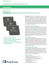
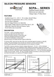
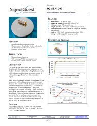
<strong>MPU</strong>-<strong>6000</strong>/<strong>MPU</strong>-<strong>6050</strong> <strong>Product</strong> <strong>Specification</strong>Document Number: PS-<strong>MPU</strong>-<strong>6000</strong>A-00<strong>Revision</strong>: <strong>1.0</strong>Release Date: 11/24/2010CommunicationsAfter beginning communications with the START condition (S), the master sends a 7-bit slave addressfollowed by an 8 th bit, the read/write bit. The read/write bit indicates whether the master is receiving data fromor is writing to the slave device. Then, the master releases the SDA line <strong>and</strong> waits for the acknowledgesignal (ACK) from the slave device. Each byte transferred must be followed by an acknowledge bit. Toacknowledge, the slave device pulls the SDA line LOW <strong>and</strong> keeps it LOW for the high period of the SCL line.Data transmission is always terminated by the master with a STOP condition (P), thus freeing thecommunications line. However, the master can generate a repeated START condition (Sr), <strong>and</strong> addressanother slave without first generating a STOP condition (P). A LOW to HIGH transition on the SDA line whileSCL is HIGH defines the stop condition. All SDA changes should take place when SCL is low, with theexception of start <strong>and</strong> stop conditions.SDASCL1 – 7 8 9 1 – 7 8 9 1 – 7 8 9SSTARTconditionADDRESS R/W ACK DATA ACK DATA ACK STOPconditionPComplete I 2 C Data TransferTo write the internal <strong>MPU</strong>-60X0 registers, the master transmits the start condition (S), followed by the I 2 Caddress <strong>and</strong> the write bit (0). At the 9 th clock cycle (when the clock is high), the <strong>MPU</strong>-60X0 acknowledges thetransfer. Then the master puts the register address (RA) on the bus. After the <strong>MPU</strong>-60X0 acknowledges thereception of the register address, the master puts the register data onto the bus. This is followed by the ACKsignal, <strong>and</strong> data transfer may be concluded by the stop condition (P). To write multiple bytes after the lastACK signal, the master can continue outputting data rather than transmitting a stop signal. In this case, the<strong>MPU</strong>-60X0 automatically increments the register address <strong>and</strong> loads the data to the appropriate register. Thefollowing figures show single <strong>and</strong> two-byte write sequences.Single-Byte Write SequenceMaster S AD+W RA DATA PSlave ACK ACK ACKBurst Write SequenceMaster S AD+W RA DATA DATA PSlave ACK ACK ACK ACKCONFIDENTIAL & PROPRIETARY 34 of 53