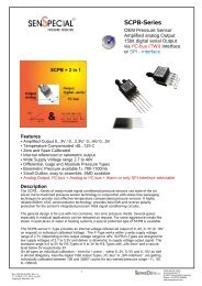
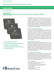
<strong>MPU</strong>-<strong>6000</strong>/<strong>MPU</strong>-<strong>6050</strong> <strong>Product</strong> <strong>Specification</strong>Document Number: PS-<strong>MPU</strong>-<strong>6000</strong>A-00<strong>Revision</strong>: <strong>1.0</strong>Release Date: 11/24/20107.5 Block DiagramCLKINCLKOUT122CLOCKClock<strong>MPU</strong>-60X0SelftestX AccelY AccelZ AccelX GyroY GyroZ GyroADCADCADCADCADCADCSignal ConditioningInterruptStatusRegisterFIFOConfigRegistersSensorRegistersFactoryCalibrationSlave I2C <strong>and</strong>SPI SerialInterfaceMaster I2CSerialInterfaceDigital MotionProcessor(DMP)SerialInterfaceBypassMux128923247611INT(/CS)AD0 / (SDO)SCL / (SCLK)SDA / (SDI)AUX_CLAUX_DAFSYNCTemp SensorADCChargePumpBias & LDO2013 18 108CPOUTVDDGNDREGOUT[VLOGIC]Note:Pin names in round brackets ( ) apply only to <strong>MPU</strong>-<strong>6000</strong>Pin names in square brackets [ ] apply only to <strong>MPU</strong>-<strong>6050</strong>7.6 OverviewThe <strong>MPU</strong>-60X0 is comprised of the following key blocks <strong>and</strong> functions:• Three-axis MEMS rate gyroscope sensor with 16-bit ADCs <strong>and</strong> signal conditioning• Three-axis MEMS accelerometer sensor with 16-bit ADCs <strong>and</strong> signal conditioning• Digital Motion Processor (DMP) engine• Primary I 2 C <strong>and</strong> SPI (<strong>MPU</strong>-<strong>6000</strong> only) serial communications interfaces• Auxiliary I 2 C serial interface for 3 rd party magnetometer & other sensors• Clocking• Sensor Data Registers• FIFO• Interrupts• Digital-Output Temperature Sensor• Self-test• Bias <strong>and</strong> LDO• Charge PumpCONFIDENTIAL & PROPRIETARY 22 of 53
<strong>MPU</strong>-<strong>6000</strong>/<strong>MPU</strong>-<strong>6050</strong> <strong>Product</strong> <strong>Specification</strong>Document Number: PS-<strong>MPU</strong>-<strong>6000</strong>A-00<strong>Revision</strong>: <strong>1.0</strong>Release Date: 11/24/20107.7 Three-Axis MEMS Gyroscope with 16-bit ADCs <strong>and</strong> Signal ConditioningThe <strong>MPU</strong>-60X0 consists of three independent vibratory MEMS rate gyroscopes, which detect rotation aboutthe X, Y, <strong>and</strong> Z axes. When the gyros are rotated about any of the sense axes, the Coriolis Effect causes avibration that is detected by a capacitive pickoff. The resulting signal is amplified, demodulated, <strong>and</strong> filteredto produce a voltage that is proportional to the angular rate. This voltage is digitized using individual on-chip16-bit Analog-to-Digital Converters (ADCs) to sample each axis. The full-scale range of the gyro sensorsmay be digitally programmed to ±250, ±500, ±1000, or ±2000 degrees per second (dps). The ADC samplerate is programmable from 8,000 samples per second, down to 3.9 samples per second, <strong>and</strong> user-selectablelow-pass filters enable a wide range of cut-off frequencies.7.8 Three-Axis MEMS Accelerometer with 16-bit ADCs <strong>and</strong> Signal ConditioningThe tri-axis accelerometer uses separate proof masses for each axis. Acceleration along a particular axisinduces displacement on the respective proof mass, <strong>and</strong> capacitive sensors detect the displacementdifferentially. The architecture reduces the susceptibility to fabrication variations as well as to thermal drift.When the device sits on a flat surface, it will measure 0g on the X- <strong>and</strong> Y-axes <strong>and</strong> +1g on the Z-axis.Accelerometer scale factor is calibrated at the factory <strong>and</strong> is nominally independent of supply voltage. Eachsensor has a dedicated sigma-delta ADC for providing digital outputs. The full scale range of the digitaloutput can be adjusted to ±2g, ±4g, ±8g, or ±16g.7.9 Digital Motion ProcessorThe embedded Digital Motion Processor (DMP) is located within the <strong>MPU</strong>-60X0 <strong>and</strong> offloads computation ofmotion processing algorithms from the host processor. The DMP acquires data from accelerometers,gyroscopes, <strong>and</strong> additional sensors such as magnetometers, <strong>and</strong> processes the data. The resulting data canbe read from the DMP’s registers, or can be buffered in a FIFO. The DMP has access to one of the <strong>MPU</strong>’sexternal pins, which can be used for generating interrupts.The purpose of the DMP is to offload both timing requirements <strong>and</strong> processing power from the hostprocessor. Typically, motion processing algorithms should be run at a high rate, often around 200Hz, in orderto provide accurate results with low latency. This is required even if the application updates at a much lowerrate; for example, a low power user interface may update as slowly as 5Hz, but the motion processing shouldstill run at 200Hz. The DMP can be used as a tool in order to minimize power, simplify timing <strong>and</strong> thesoftware architecture, <strong>and</strong> save valuable MIPS on the host processor for use in the application.7.10 Primary I 2 C <strong>and</strong> SPI Serial Communications InterfacesThe <strong>MPU</strong>-60X0 communicates to a system processor using either SPI (<strong>MPU</strong>-<strong>6000</strong> only) or I 2 C serialinterfaces, <strong>and</strong> the device always acts as a slave when communicating to the system processor. The logiclevel for communications to the master is set by the voltage on the VLOGIC pin – (<strong>MPU</strong>-<strong>6050</strong>) or by VDD(<strong>MPU</strong>-<strong>6000</strong>). The LSB of the of the I 2 C slave address is set by pin 9 (AD0).CONFIDENTIAL & PROPRIETARY 23 of 53