AN Event-Driven Arduino™ Programming with QP™ - Quantum Leaps
AN Event-Driven Arduino™ Programming with QP™ - Quantum Leaps
AN Event-Driven Arduino™ Programming with QP™ - Quantum Leaps
- No tags were found...

You also want an ePaper? Increase the reach of your titles
YUMPU automatically turns print PDFs into web optimized ePapers that Google loves.
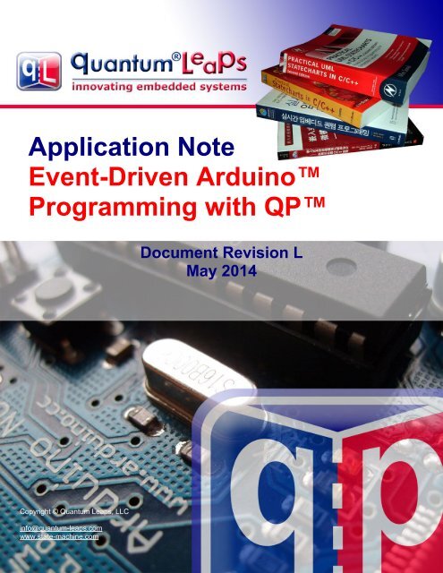
QP state machine frameworks for ArduinoApplication Note<strong>Event</strong>-<strong>Driven</strong> Arduino<strong>Programming</strong> <strong>with</strong> QPDocument Revision LMay 2014Copyright © <strong>Quantum</strong> <strong>Leaps</strong>, LLCinfo@quantum-leaps.comwww.state-machine.comCopyright © 2002-2006, <strong>Quantum</strong> <strong>Leaps</strong>, LLC. All Rights Reserved.i
Application Note:<strong>Event</strong>-<strong>Driven</strong> Arduino <strong>Programming</strong> <strong>with</strong> QPstate-machine.com/arduino1.2 <strong>Event</strong>-driven programming <strong>with</strong> ArduinoTraditionally, Arduino programs are written in a sequential manner.Whenever an Arduino program needs to synchronize <strong>with</strong> some externalevent, such as a button press, arrival of a character through the serial port, ora time delay, it explicitly waits in-line for the occurrence of the event. Waiting“in-line” means that the Arduino processor spends all of its cycles constantlychecking for some condition in a tight loop (called the polling loop). Forexample, in almost every Arduino program you see many polling loops likethe code snippet below, or function calls, like delay() that contain implicitpolling loops inside:Listing 1: Sequential programming examplevoid loop() {while (digitalRead(buttonPin) != HIGH) ; // wait for the button press. . . // process the button presswhile (Serial.available() == 0) ; // wait for a character from the serial portchar ch = Serial.read(); // obtain the character. . . // process the characterdelay(1000); // implicit polling loop (wait for 1000ms). . . // process the timeout, e.g., switch an LED on}Although this approach is functional in many situations, it doesn't work very well when there are multiplepossible sources of events whose arrival times and order you cannot predict and where it is important tohandle the events in a timely manner. The fundamental problem is that while a sequential program iswaiting for one kind of event (e.g., a button press), it is not doing any other work and is not responsive toother events (e.g., characters from the serial port).Another big problem <strong>with</strong> the sequential program structure is wastefulness in terms of power dissipation.Regardless of how much or how little actual work is being done, the Arduino processor is always runningat top speed, which drains the battery quickly and prevents you from making truly long-lasting batterypowereddevices.NOTE: If you intend to use Arduino in a battery operated device, you should seriously consider theevent-driven programming option. Please also see the upcoming Section 2.6.For these and other reasons experienced programmers turn to the long-know design strategy calledevent-driven programming, which requires a distinctly different way of thinking than conventionalsequential programs. All event-driven programs are naturally divided into the application, which actuallyhandles the events, and the supervisory event-driven infrastructure (framework), which waits for eventsand dispatches them to the application. The control resides in the event-driven framework, so from theapplication standpoint, the control is inverted compared to a traditional sequential program.Listing 2: The simplest event-driven program structure. The highlighted codeconceptually belongs to the event-driven framework.void loop() {if (event1()) // event1 occurred?event1Handler(); // process event1if (event2()) // event2 occurred?event2Handler(); // process event2. . . // handle other events}Copyright © <strong>Quantum</strong> <strong>Leaps</strong>, LLC. All Rights Reserved.2 of 36
Application Note:<strong>Event</strong>-<strong>Driven</strong> Arduino <strong>Programming</strong> <strong>with</strong> QPstate-machine.com/arduinoAn event-driven framework can be very simple. In fact, many projects in the Arduino Playground /Tutorials and Resources / Protothreading, Timing & Millis section provide examples of rudimentary eventdrivenframeworks. The general structure of all these rudimentary frameworks is shown in Listing 2.The framework in this case consists of the main Arduino loop and the if statements that check forevents. <strong>Event</strong>s are effectively polled during each pass through the main loop, but the main loop does notget into tight polling sub-loops. Calls to functions that poll internally (like delay()) are not allowed,because they would slow down the main loop and defeat the main purpose of event-driven programming(responsiveness). The application in this case consists of all the event handler functions(event1Handler(), event2Handler(), etc.). Again, the critical difference from sequential programminghere is that the event handler functions are not allowed to poll for events, but must consist essentially oflinear code that quickly returns control to the framework after handling each event.This arrangement allows the event-driven program to remain responsive to all events all the time, but it isalso the biggest challenge of the event-driven programming style, because the application (the eventhandler functions) must be designed such that for each new event the corresponding event handler canpick up where it left off for the last event. (A sequential program has much less of this problem, because itcan hang on in tight polling loops around certain places in the code and process the events in thecontexts just following the polling loops. This arrangement allows a sequential program to move naturallyfrom one event to the next.)Unfortunately, the just described main challenge of event-driven programming often leads to “spaghetti”code. The event handler functions start off pretty simple, but then if-s and else-s must be added insidethe handler functions to handle the context properly. For example, if you design a vending machine, youcannot process the “dispense product” button-press event until the full payment has been collected. Thismeans that somewhere inside the dispenseProductButtonPressHandler() function you need an ifstatementthat tests the payment status based on some global variable, which is set in the event handlerfunction for payment events. Conversely, the payment status variable must be changed after dispensingthe product or you will allow dispensing products <strong>with</strong>out collecting subsequent payments. Hopefully yousee how this design quickly leads to dozens of global variables and hundreds of tests (if-s and else-s)spread across the event handler functions, until no human being has an idea what exactly happens forany given event, because the event-handler code resembles a bowl of tangled spaghetti. An example ofspaghetti code just starting to develop is the Stopwatch project available from the Arduino Playground.Luckily, generations of programmers before you have discovered an effective way of solving the“spaghetti” code problem. The solution is based on the concept of a state machine, or actually a set ofcollaborating state machines that preserve the context from one event to the next using the concept ofstate. This document describes this most advanced and powerful way of combining the event-drivenprogramming paradigm <strong>with</strong> modern state machines.1.3 The structure of the QP/C++ event-driven framework for ArduinoThe rudimentary examples of event-driven programs currently available from the Arduino Playground arevery simple, but they don't provide a true event-driven programming environment for a number ofreasons. First, the simple frameworks don't perform queuing of events, so events can get lost if an eventhappens more than once before the main loop comes around to check for this event or when an event isgenerated in the loop. Second, the primitive event-driven frameworks have no safeguards againstcorruption of the global data shared among the event-handlers by the interrupt service routines (ISRs),which can preempt the main loop at any time. And finally, the simple frameworks are not suitable forexecuting state machines due to the early filtering by event-type, which does not leave room for statemachine(s) to make decisions based on the internal state.Figure 2 shows the structure of the QP framework for Arduino, which does provide all the essentialelements for safe and efficient event-driven programming. As usual, the software is structured in anendless event loop. The most important element of the design is the presence of multiple event queues<strong>with</strong> a unique priority and a state machine assigned to each queue. The queues are constantlymonitored by the “vanilla” scheduler, which by every pass through the loop picks up the highest-priorityCopyright © <strong>Quantum</strong> <strong>Leaps</strong>, LLC. All Rights Reserved.3 of 36
Application Note:<strong>Event</strong>-<strong>Driven</strong> Arduino <strong>Programming</strong> <strong>with</strong> QPstate-machine.com/arduino2 Getting StartedTo focus the discussion, this Application Note uses the Arduino UNOboard based on the Atmel Atmega328P microcontroller (see Figure 3).The example code has been built entirely inside the QM modeling tool(version 3.1.x or higher), but it uses the compiler and libraries in thestandard Arduino 1.0.x, which is available for a free download from theArduino website.NOTE: The tools and procedures for building and uploading Arduinosketches will not work <strong>with</strong> the Arduino 1.5.x toolset, because it hasa very different structure than Arduino 1.0.x.Figure 3: Arduino UNO boardStandard Arduinopin-headerUser LEDReset buttonAtmega328PmicrocontrollerUSB Connectorto the host PCStandard Arduinopin-headerNOTE: The following discussion assumes that you have downloaded and installed both the standardArduino software and the QM tool on your computer. The free QM tool can be downloaded from:https://sourceforge.net/projects/qpc/files/QM. Just like the standard Arduino IDE, QM is available forWindows, Linux, and Mac OS X hosts.Copyright © <strong>Quantum</strong> <strong>Leaps</strong>, LLC. All Rights Reserved.5 of 36
Application Note:<strong>Event</strong>-<strong>Driven</strong> Arduino <strong>Programming</strong> <strong>with</strong> QPstate-machine.com/arduino2.1 Software InstallationThe example code is distributed in a single ZIP archive qp_arduino_, where stands for theArduino software version numer (e.g., 1.0.x). The contents of this archive is shown in Listing 3.Listing 3: Contents of the qp_arduino_.zip archive for Arduion 1.0.xqp_arduino_.zip - the code accompanying this application note+-doc/- documentation| +-<strong>AN</strong>_<strong>Event</strong>-<strong>Driven</strong>_Arduino.pdf – this document| +-<strong>AN</strong>_DPP.pdf – Dining Philosopher Problem example application| +-<strong>AN</strong>_PELIC<strong>AN</strong>.pdf – PEdestrian LIght CONtrolled (PELIC<strong>AN</strong>) crossing example|+-hardware/| +-arduino/| | +-libraries/ ==> goes to /hardware/arduino/libraries/ folder| | | +-QP/ - QP library for AVR-based Arduinos| | | | +-examples/ - Examples for the QP library| | | | | +-blinky/ – Very simple “blinky” example| | | | | | +-.blinky - The QM session file for the Blinly project| | | | | | +-blinky.qm - The QM model of the Blinky application| | | | | +-dpp_qk/ – DPP-QK example <strong>with</strong> preemptive QK kernel (Section 7)| | | | | | +-.dpp - The QM session file for the DPP project| | | | | | +-dpp.qm - The QM model of the DPP application| | | | | +-pelican/ – PEdestrian LIght CONtrolled (PELIC<strong>AN</strong>) crossing example| | | | | | +-.pelican - The QM session file for the PELIC<strong>AN</strong> project| | | | | | +-pelican.qm- The QM model of the PELCI<strong>AN</strong> crossing application| | | | || | | | +-COPYING.txt - terms of copying this code| | | | +-GPL2.TXT - GPL version 2 open source license| | | | +-qp.cpp - QP/C++ platform-independent implementation| | | | +-qp_port.cpp - QP/C++ port for Arduino implementation| | | | +-qp_port.h - QP/C++ port for Arduino interface|+-tools/==> goes to the /tools/ folder| +-qtools/ - tools contributed <strong>Quantum</strong> <strong>Leaps</strong>| | +-avrmake.tcl – Generic TCL script for building Arduino/AVR sketches| | +-COPYING.txt - terms of copying this code| | +-GPL2.TXT - GPL version 2 open source license| | +-rm.exe – Command-line utility for removing files (cleanup)The complete QP/C++ library code consists of just three source files: qp_port.h, qp_port.cpp, andqp.cpp. The QP library is accompanied <strong>with</strong> three examples: blinky, pelican, and dpp_qk. TheArduino sketch blinky demonstrates the very simple “blinky” sketch that blinks the User LED on theArduino board. The sketch pelican demonstrates a PEdestrian LIght CONtrolled (PELIC<strong>AN</strong>) crossing<strong>with</strong> a non-trivial hierarchical state machine. The scketch dpp_qk demonstrates the cassic DiningPhilosopher Problem (DPP) <strong>with</strong> multiple state machines and the preemptive QK kernel. All examplescontain the QM models to generate the Arduino code automatically.You need to unzip the qp_arduino_.zip archive into the Arduino directory (e.g., C:\ProgramFiles (x85)\Arduino\). On Windows you can simply open the ZIP file <strong>with</strong> the Windows Explorer,select the three directories (libraries/ examples/, and tools/) and drag (or copy-and-paste) them tothe Arduino directory, as shown in Figure 4. Since Arduino already has the libraries/ examples/,and tools/ folders, you need to confirm that you want to merge these folders.Copyright © <strong>Quantum</strong> <strong>Leaps</strong>, LLC. All Rights Reserved.6 of 36
Application Note:<strong>Event</strong>-<strong>Driven</strong> Arduino <strong>Programming</strong> <strong>with</strong> QPstate-machine.com/arduinoFigure 4: Unzipping qp_arduino_.zip into the Arduino directory.You need to confirm that you want to merge the folders libraries and tools.Each QP example for Arduino contains a QM model, which is a file <strong>with</strong> the extension .qm. For example,\hardware\arduino\avr\libraries\qp\examples\pelican-\pelican.qm, see Listing 3). These models and the QM modeling tool take Arduino programming to thenext level. Instead of coding the state machines by hand, you draw them <strong>with</strong> the free QM modeling tool,attach simple action code to states and transitions, and you generate the complete Arduino sketchautomatically—literally by a press of a button (see Figure 5).NOTE: To start working <strong>with</strong> the QM modeling tool, you need to download the tool fromSourceforge.net . QM is free to download and free to use (see also Related Documents andReferences).Copyright © <strong>Quantum</strong> <strong>Leaps</strong>, LLC. All Rights Reserved.7 of 36
Application Note:<strong>Event</strong>-<strong>Driven</strong> Arduino <strong>Programming</strong> <strong>with</strong> QPstate-machine.com/arduino2.2 Building and Running the Blinky Example from the QM Modeling ToolTo build the provided Blinly example, change to the \libraries\QP\examples\blinkydirectory, and double-click on the blinky.qm model file. If you installed QM correctly, this will open theBlinky model in the QM tool, as shown in Figure 5. You build and upload the QP examples directlyfrom the QM modeling tool, <strong>with</strong>out the need to launch the standad Arduino IDE.NOTE: The provided QP examples for Arduino are still compatible <strong>with</strong> the standard Arduino IDE, soyou can still use the Arduino IDE, if you chose to do so, to build and upload the examples to yourArduino board.Figure 5: The QM modeling tool showing the Blinky model and the External Toolsconfigured for working <strong>with</strong> Arduino.Build CodeButton (F7)Clean BuildButton (F8)Clean BuildButton (F9)Manag External ToolsButtonClean AllButton (F12)Serial TerminalButton (F11)Upload CodeButton (F10)But before you can build the code, you need to adjust the location of the standard Arduino software, sothat the build process can find the compiler and other required tools. You do this by clicking the ManageExternal Tools Button (see Figure 5) and edit the environment variable ARDUINO_HOME to the location ofthe standard Arduino software on your computer. You can also edit the parameters of your Arduino board(BOARD_MCU, BOARD_VARI<strong>AN</strong>T, and BOARD_F_CPU) as well as the COM port used by your board(BOARD_COM and BOARD_BAUD). Please refer to Section 6 for more details.Copyright © <strong>Quantum</strong> <strong>Leaps</strong>, LLC. All Rights Reserved.8 of 36
Application Note:<strong>Event</strong>-<strong>Driven</strong> Arduino <strong>Programming</strong> <strong>with</strong> QPstate-machine.com/arduinoFigure 6: Adjusting the ARDUINO_HOME environment variable in theManage External Tools DialogAdjust for yoursystemNOTE: The Manage External Tools dialog box allows you to configure up to five different externaltools. The described configuration is included in the QP examples for Arduino, but you can modify thetools to suit your needs at any timeAfter you've adjusted the environment variables, click on the Build button (see Figure 5). The first timebuild takes a little longer, because it performs a clean build of all the libraries you've specified for thisproject. For the Blinky project, this includes the standard Arduino library plus the QP framework. Thesubsequent builds are much faster, because only the project files that have changed are re-built.To upload the code to your Arduino board, you must connect the board to your computer via a USB cable.You upload the code to the Arduino microcontroller by pressing the Upload button. Please note that theupload can take several seconds to complete. After the upload, your Arduino starts executing theexample. You should see the User LED blink at the rate of about once per second (see Figure 3).Copyright © <strong>Quantum</strong> <strong>Leaps</strong>, LLC. All Rights Reserved.9 of 36
Application Note:<strong>Event</strong>-<strong>Driven</strong> Arduino <strong>Programming</strong> <strong>with</strong> QPstate-machine.com/arduinoFigure 7: Uploading the code to the Arduino boardUpload CodeButton (F10)Log window showing theoutput from avrdude2.3 Building and Running the Blinky Example from the Arduino IDEAs mentioned before, the QP examples are still compatible <strong>with</strong> the standard Arduino IDE. For example,to build and run the Blinky example, you lanuch the Arduino Ide and open the blinky project as shownFigure 8.Copyright © <strong>Quantum</strong> <strong>Leaps</strong>, LLC. All Rights Reserved.10 of 36
Application Note:<strong>Event</strong>-<strong>Driven</strong> Arduino <strong>Programming</strong> <strong>with</strong> QPstate-machine.com/arduinoFigure 8: Launching the Blinky example from the Arduino IDEExample projectsfor the QP libraryNOTE: Even though you can build the example code <strong>with</strong> the Arduino IDE, you still need to use QMto (re)generate the code. If you don't wish to use QM at all, you can code the state machines byhand, which is not that hard, because the underlying QP framework has been specifically designedfor manual coding of state machines.Copyright © <strong>Quantum</strong> <strong>Leaps</strong>, LLC. All Rights Reserved.11 of 36
Application Note:<strong>Event</strong>-<strong>Driven</strong> Arduino <strong>Programming</strong> <strong>with</strong> QPstate-machine.com/arduino2.4 Running the PELIC<strong>AN</strong> Crossing Example in the QM toolThe PEdestrian LIght CONtrolled (PELIC<strong>AN</strong>) crossing example is built and uploaded in the similar way asthe Blinky example, except you open the pelican.qm example QM model located in the directory\hardware\arduino\avr\libraries\QP\examples\pelican.Before you can test the example, you need to understand the how it is supposed to work. So, thePELIC<strong>AN</strong> crossing operates as follows: The crossing (see Figure 9) starts <strong>with</strong> cars enabled (green lightfor cars) and pedestrians disabled (“Don't Walk” signal for pedestrians). To activate the traffic light changea pedestrian must push the button at the crossing, which generates the PEDS_WAITING event. Inresponse, oncoming cars get the yellow light, which after a few seconds changes to red light. Next,pedestrians get the “Walk” signal, which shortly thereafter changes to the flashing “Don't Walk” signal.After the “Dont' Walk” signal stops flashing, cars get the green light again. After this cycle, the traffic lightsdon't respond to the PEDS_WAITING button press immediately, although the button “remembers” that ithas been pressed. The traffic light controller always gives the cars a minimum of several seconds ofgreen light before repeating the traffic light change cycle. One additional feature is that at any time anoperator can take the PELIC<strong>AN</strong> crossing offline (by providing the OFF event). In the “offline” mode thecars get the flashing red light and the pedestrians get the flashing “Don't Walk” signal. At any time theoperator can turn the crossing back online (by providing the ON event).NOTE: The design and implementation of the PELIC<strong>AN</strong> crossing application, including the PELIC<strong>AN</strong>state machine, is described in the Application Note “PELIC<strong>AN</strong> Crossing Application” (see RelatedDocuments and References).Figure 9: Pedestrian Light CONtrolled (PELIC<strong>AN</strong>) crossingSignals forpedestriansSignals forcarsPEDS_WALKbuttonAfter you build and upload the software to the Arduino UNO board, the User LED should start to glow <strong>with</strong>low intensity (not full on). In the PELIC<strong>AN</strong> example, the User LED is rapidly turned on and off in theArduino idle loop, which appears as a constant glow to a human eye.To see the actual output from the PELIC<strong>AN</strong> example, you need to open a Serial Terminal by pressingthe Serial Terminal button on the QM toolbar (see Figure 5). For the Arduino UNO board, the SerialTerminal should be configured to 115200 baud rate. To activate the PELIC<strong>AN</strong> crossing, type 'p' on theterminal. This will trigger the sequence of signals for cars and pedestrians, as shown in Figure 10.NOTE: The Serial Terminal button opens the Tera Term application, which a freeware serail terminalapplication for Winows that you need to install separately (see http://ttssh2.sourceforge.jp). You canalso use any other serial terminal software instead.Copyright © <strong>Quantum</strong> <strong>Leaps</strong>, LLC. All Rights Reserved.12 of 36
Application Note:<strong>Event</strong>-<strong>Driven</strong> Arduino <strong>Programming</strong> <strong>with</strong> QPstate-machine.com/arduino2.5 The Dining Philosophers Problem Example <strong>with</strong> the Preemptive QK Kernel.Finally, the example code contains the Dining Philosphers Problem (DPP) example, which demonstratesmutilple state machines and the preemptive QK kernel (see also Section 7). This example is located inthe directory \hardware\arduino\avr\libraries\QP\examples\dpp_qk.The classical Dining Philosopher Problem (DPP) was posed and solved originally by Edsger Dijikstra inthe 1970s and is specified as follows: Five philosophers are gathered around a table <strong>with</strong> a big plate ofspaghetti in the middle (see Figure 11). Between each two philosophers is a fork. The spaghetti is soslippery that a philosopher needs two forks to eat it. The life of a philosopher consists of alternate periodsof thinking and eating. When a philosopher wants to eat, he tries to acquire forks. If successful inacquiring forks, he eats for a while, then puts down the forks and continues to think. The key issue is thata finite set of tasks (philosophers) is sharing a finite set of resources (forks), and each resource can beused by only one task at a time.Figure 11: Dining Philosophers ProblemYou build and upload the DPP-QK example to the Arduino UNO board the same way as the PELIC<strong>AN</strong>example. Just like in the PELIC<strong>AN</strong> example, the User LED in DPP-QK is rapidly turned on and off in theidle loop, which appears as a constant glow to a human eye.To see the actual output from the DPP-QK example, you need to open a Serial Terminal by pressing theSerial Terminal button on the QM toolbar (see Figure 5). For the Arduino UNO board, the Serial Terminalshould be configured to 115200 baud rate.TeraTerm SerialTerminal windowCopyright © <strong>Quantum</strong> <strong>Leaps</strong>, LLC. All Rights Reserved.14 of 36
Application Note:<strong>Event</strong>-<strong>Driven</strong> Arduino <strong>Programming</strong> <strong>with</strong> QPstate-machine.com/arduino2.6 Modifying the Examples to Reduce Power ConsumptionAs mentioned in Section 1.2, the QP/C++ framework allows you to take advantage of the Arduinoprocessor's low-power sleep mode, which is the only way to achieve really low-power design. Bothprovided examples can be very easily modified to switch to the sleep mode when no events are available.In fact, the code is already provided for you, so all you need to do is just to enable this code. As shown inListing 9, you uncomment the definition of the SAVE_POWER macro in the file bsp.cpp (Board SupportPackage).After you recompile the code and download to Arduino, you will see that the User LED is no longerglowing. Actually, it is glowing, but only for a few microseconds out of every 10 milliseconds, so youcannot see it. This very low brightness of the User LED means that the Arduino Background loop usesvery little power, yet the application performs exactly as before! The upcoming Section 4.1 explains whatexactly happens when you define the macro SAVE_POWER in bsp.cpp.Copyright © <strong>Quantum</strong> <strong>Leaps</strong>, LLC. All Rights Reserved.15 of 36
Application Note:<strong>Event</strong>-<strong>Driven</strong> Arduino <strong>Programming</strong> <strong>with</strong> QPstate-machine.com/arduino3 The Structure of an Arduino Sketch for QPEvery event-driven Arduino sketch for QP consists of four rough groups: setup, events, active objects,and board support package (BSP). Typically, the main sketch file (the .ino file) contains the Aruinosetup() function. Since the events are shared, they are defined in a header file (the .h file). Activeobjects are defined in source files (the .cpp files), one active object per file. The following sectionsdescribe these elements in more detail.3.1 The setup() functionListing 4 shows an example Arduino sketch for QP. This sketch defines only the setup() function. Theexplanation section immediately following the listing highlights the main points.Listing 4: Typical Arduino sketch for QP (file dpp.ino)(0) #include "Arduino.h" // don't forget to include!!!(1) #include "qp_port.h"(2) #include "dpp.h"(3) #include "bsp.h"// Local-scope objects -------------------------------------------------------(4) static QEvt const *l_tableQueueSto[N_PHILO];(5) static QEvt const *l_philoQueueSto[N_PHILO][N_PHILO];(6) static QSubscrList l_subscrSto[MAX_PUB_SIG];(7) QF_MPOOL_EL(TableEvt) l_smlPoolSto[2*N_PHILO]; // storage for small event pool//............................................................................(8) void setup() {(9) BSP_init(); // initialize the BSP(10) QF::init(); // initialize the framework and the underlying RT kernel// initialize event pools...(11) QF::poolInit(l_smlPoolSto, sizeof(l_smlPoolSto), sizeof(l_smlPoolSto[0]));(12) QF::psInit(l_subscrSto, Q_DIM(l_subscrSto)); // init publish-subscribe// start the active objects...uint8_t n;for (n = 0; n < N_PHILO; ++n) {(13) AO_Philo[n]->start((uint8_t)(n + 1),l_philoQueueSto[n], Q_DIM(l_philoQueueSto[n]));}(14) AO_Table->start((uint8_t)(N_PHILO + 1),l_tableQueueSto, Q_DIM(l_tableQueueSto));}(0) Each sketch for must include the standard "Arduino.h" header file. This is necessary to make thesketch compatible <strong>with</strong> the arduinomake.tcl build script (see also Section ???)(1) Each sketch for QP imports the QP library port to Arduino (the header file).(2) The application header file (dpp.h in this case) contains the definition of signals and events for theapplication. This file is shared among most files in the sketch.Copyright © <strong>Quantum</strong> <strong>Leaps</strong>, LLC. All Rights Reserved.16 of 36
Application Note:<strong>Event</strong>-<strong>Driven</strong> Arduino <strong>Programming</strong> <strong>with</strong> QPstate-machine.com/arduino(3) The header file bsp.h contains the facilities provided by the Board Support Package. This file is alsoshared among most files in the sketch.(4-5) The application must provide storage for event queues of all active objects used in the application.Here the storage is provided at compile time through the statically allocated arrays of immutable(const) pointers to events.(6) If the application uses the publish-subscribe event delivery mechanism supported by QP, theapplication must provide the storage for the subscriber lists. The subscriber lists remember whichactive objects have subscribed to which events. The size of the subscriber database depends on thenumber of published events MAX_PUB_SIG found in the application header file.(7) The application must also provide storage for the event pools that the QP framework uses for fastand deterministic dynamic allocation of events. Each event pool can provide only fixed-size memoryblocks. To avoid wasting the precious memory (RAM) by using massively oversized pools, the QPframework can manage up to three event pools of different sizes. The DPP application uses onlyone pool, which can hold TableEvt events and events <strong>with</strong>out parameters (QEvt).(8) You provide only the definition of the Arduino setup() function. You don't define the loop()function, because it is provided in the framework (see Section 5.2).(9) The function BSP_init() initializes the Arduino board for this application and is defined in thebsp.cpp file.(10) The function QF::init() initializes the QF framework and you need to call it before any other QFservices.(11) The function QF::poolInit() initializes the event pool. The parameters of this function are: thepointer to eh event pool storage, the size of this storage, and the block-size of the this pool. You cancall this function up to three times to initialize up to three event pools. The subsequent calls toQF::poolInit() must be made in the increasing order of block-size. For instance, the small blocksizepool must be initialized before the medium block-size pool(12) The function QF::psInit() initializes the publish-subscribe event delivery mechanism of QP. Theparameters of this function are: the pointer to the subscriber-list array and the dimension of thisarray.NOTE: The utility macro Q_DIM() provides the dimension of a one-dimensional array a[] computedas sizeof(a)/sizeof(a[0]), which is a compile-time constant.(13-14) The function start() is defined in the framework class QActive and tells the framework to startmanaging an active object as part of the application. The function takes the following parameters:the pointer to the active object, the priority of the active object, the pointer to its event queue, thedimension (length) of that queue. The active object priorities in QP are numbered from 1 toQF_MAX_ACTIVE, inclusive, where a higher priority number denotes higher urgency of the activeobject. The constant QF_MAX_ACTIVE is defined in the QP port header file qf_port.h (seeSection 5.1).At this point you have provided the QP framework <strong>with</strong> all the storage and active object information itneeds to manage your application. The next step of execution of the Arduino sketch is the call to theloop() function, which is defined in the QP port to Arduino. As described in the upcoming Section 5.2,the loop() function executes the main event-loop shown in Figure 2.NOTE: You do NOT provide the defnition of the Arduino loop() function.Copyright © <strong>Quantum</strong> <strong>Leaps</strong>, LLC. All Rights Reserved.17 of 36
Application Note:<strong>Event</strong>-<strong>Driven</strong> Arduino <strong>Programming</strong> <strong>with</strong> QPstate-machine.com/arduino3.2 The Application Interface (<strong>Event</strong>s and Signals)An event represents occurrence that is interesting to the system. An event consists of two parts. The partof the event called the signal conveys the type of the occurrence (what happened). For example, in theDPP application the EAT_SIG signal represents the permission to eat to a Philosopher active object,whereas HUNGRY_SIG conveys to the Table active object that a Philosopher wants to eat. An event canalso contain additional quantitative information about the occurrence in the form of event parameters.For example, the HUNGRY_SIG signal is accompanied by the number of the Philosopher. In QP eventsare represented as instances of the QEvt class provided by the framework. Specifically, the QEvt classcontains the member sig, to represent the signal of that event. <strong>Event</strong> parameters are added in thesubclasses of QEvt, that is classes that inherit from QEvt.Because events are shared among most of the application components, it is convenient to declare themin a separate header file (e.g., dpp.h for the DPP application). Listing 5 shows the interface for the DPPapplication. The explanation section immediately following the listing highlights the main points.Listing 5: The application header file for DPP (file dpp.h)(1) using namespace QP;//assume the QP namespace for all files in this application(2) enum DPPSignals {(3) EAT_SIG = Q_USER_SIG, // published by Table to let a philosopher eatDONE_SIG,// published by Philosopher when done eatingTERMINATE_SIG,// published by BSP to terminate the application(4) MAX_PUB_SIG, // the last published signalHUNGRY_SIG,// posted from hungry Philosopher to Table(5) MAX_SIG // the last signal};(6) struct TableEvt : public QEvt {uint8_t philoNum;};enum { N_PHILO = 5 };// philosopher number// number of philosophers(1) This directive establishes the default namespace to be QP, meaning that all elements not qualifiedexplicitly are assumed to come from the namespace QP.NOTE: Starting from QP version 4.5.xx, the directive “using namespace QP” is necessary touse the QP framework <strong>with</strong>out explicitly adding the prefix “QP::” to every element comingfrom the framework. This directive is also necessary for compatibility <strong>with</strong> the codegenerated by the QM tool version 2.3.x or higher.(2) In QP, event signals are enumerated constants. Placing all signals in a single enumeration isparticularly convenient to avoid inadvertent overlap in the numerical values of the different signals.(3) The application-level signals do not start form zero but rather must be offset by the constantQ_USER_SIG. Also note that by convention the suffix _SIG is attached to the signals, so you caneasily distinguish signals from other constants in your code. Typically the suffix _SIG is dropped inthe state diagrams to reduce the clutter.Copyright © <strong>Quantum</strong> <strong>Leaps</strong>, LLC. All Rights Reserved.18 of 36
Application Note:<strong>Event</strong>-<strong>Driven</strong> Arduino <strong>Programming</strong> <strong>with</strong> QPstate-machine.com/arduino(4) The constant MAX_PUB_SIG delimits the published signals from the rest. You can save some RAMby providing a lower limit of published signals to QP (MAX_PUB_SIG) rather than the maximum of allsignals used in the application.(5) The last enumeration MAX_SIG indicates the maximum of all signals used in the application.(6) The structure TableEvt represents a class of events to convey the Philosopher number in theevent parameter. TableEvt inherits QEvt and adds the philoNum parameter to it.(7-8) These global pointers represent active objects in the application and are used for posting eventsdirectly to active objects. Because the pointers can be initialized at compile time, they are declaredconst. The active object pointers are “opaque” because they cannot access the whole activeobject, only the part inherited from QActive.Copyright © <strong>Quantum</strong> <strong>Leaps</strong>, LLC. All Rights Reserved.19 of 36
Application Note:<strong>Event</strong>-<strong>Driven</strong> Arduino <strong>Programming</strong> <strong>with</strong> QPstate-machine.com/arduino3.3 The State MachinesThe QP framework allows you to work <strong>with</strong> the modern hierarchical state machines (a.k.a., UMLstatecharts). For example, Figure 12 shows the HSM for the PELIC<strong>AN</strong> crossing.Figure 12: The hierarchical state machine of the PELIC<strong>AN</strong> crossing/me->subscribe(PEDS_WAITING_SIG);entry / CARS_RED; PEDS_DONT_WALKoperationalOFFexit /carsEnabledexit /pedsEnabledcarsGreenentry / CARS_GREENexit /pedsWalkentry / PEDS_WALKexit /TIMEOUTcarsGreenNoPedentry /PEDS_WAITINGTIMEOUTcarsGreenIntentry /PEDS_WAITINGcarsGreenPedWaitentry /TIMEOUTentry /exit /TIMEOUT[else]pedsFlash[me->m_flashCtr != 0] /--me->m_flashCtr;[else] /BSP_signalPeds(PEDS_BL<strong>AN</strong>K);carsYellowentry / CARS_YELLOWexit /[(me->m_flashCtr 1) == 0] /BSP_signalPeds(PEDS_DONT_WALK);TIMEOUTentry /exit /ONofflineTIMEOUT /me->m_flashCtr ^= 1; [(me->m_flashCtr 1) == 0] /CARS_RED; PEDS_DONT_WALK;[else] / CARS_BL<strong>AN</strong>K; PEDS_BL<strong>AN</strong>K;Copyright © <strong>Quantum</strong> <strong>Leaps</strong>, LLC. All Rights Reserved.20 of 36
Application Note:<strong>Event</strong>-<strong>Driven</strong> Arduino <strong>Programming</strong> <strong>with</strong> QPstate-machine.com/arduinoThe biggest advantage of hierarchical state machines (HSMs) compared to the traditional finite statemachines (FSMs) is that HSMs remove the need for repetitions of actions and transitions that occur in thenon-hierarchial state machines. Without this ability, the complexity of non-hierarchical state machines“explodes” exponentially <strong>with</strong> the complexity of the modeled system, which renders the formalismimpractical for real-life problems.NOTE: The state machine concepts, state machine design, and hierarchical state machineimplementation in C++ are not specific to Arduino and are out of scope of this document. The designand implementation of the DPP example is described in the separate Application Note “DiningPhilosophers Problem” (see Related Documents and References). The PELIC<strong>AN</strong> crossing exampleis described in the Application Note “PELIC<strong>AN</strong> Crossing”. Both these application notes are includedin the ZIP file that contains the QP library and examples for Arduino (see Listing 3).Once you design your state machine(s), you can code it by hand, which the QP framewrok makesparticularly straightforward, or you can use the QM tool to generate code automatically, as described inSection 14.Copyright © <strong>Quantum</strong> <strong>Leaps</strong>, LLC. All Rights Reserved.21 of 36
Application Note:<strong>Event</strong>-<strong>Driven</strong> Arduino <strong>Programming</strong> <strong>with</strong> QPstate-machine.com/arduino4 Board Support Package (BSP) for ArduinoThe QP example sketches (DPP and PELIC<strong>AN</strong>) contain the file bsp.cpp, which stands for BoardSupport Package (BSP). This BSP contains all board-related code, which consists of the boardinitialization, interrupt service routines (ISRs), idle processing, and assertion handler. The followingsections explain these elements.4.1 BSP InitializationThe BSP initialization is done in the function BSP_init(). It is minimal, but generic for most Arduinoboards. The most important step is initialization of the User LED (connected to PORTB) and the serialport, which is used to output the data in the example applications. If you use other peripherals as well,you BSP_init() is the best for such additional initialization code.Listing 6: BSP_init() function for the DPP example (file bsp.cpp)void BSP_init(void) {DDRB = 0xFF;PORTB = 0x00;Serial.begin(115200);Serial.println("Start");}// All PORTB pins are outputs (user LED)// drive all pins low4.2 InterruptsAn interrupt is an asynchronous signal that causes the Arduino processor to save its current state ofexecution and begin executing an Interrupt Service Routine (ISR). All this happens in hardware (<strong>with</strong>outany extra code) and is very fast. After the ISR returns, the processor restores the saved state of executionand continues from the point of interruption.You need to use interrupts to work <strong>with</strong> QP. At the minimum, you must provide the system clock tickinterrupt, which allows the QP framework to handle the timeout request that active objects make. Youmight also want to implement other interrupts as well.When working <strong>with</strong> interrupts you need to be careful when you enable them to make sure that the systemis ready to receive and process interrupts. QP provides a special callback function QF::onStartup(),which is specifically designed for configuring and enabling interrupts. QF::onStartup() is called afterall initialization completes, but before the framework enters the endless event loop. Listing 7 shows theimplementation of QF::onStartup() for QP, which configures and starts the system clock tick interrupt.If you use other interrupts, you need to add them to this function as well.Listing 7: Configuring and starting interrupts in QF::onStartup()void QF::onStartup(void) {(1) // set Timer2 in CTC mode, 1/1024 prescaler, start the timer tickingTCCR2A = (1
Application Note:<strong>Event</strong>-<strong>Driven</strong> Arduino <strong>Programming</strong> <strong>with</strong> QPstate-machine.com/arduino(1) This BSP uses Timer2 as the source of the periodic clock tick interrupt (Timer1 is already used toprovide the Arduino milli() service).(3) The output compare register (OCR2A) is loaded <strong>with</strong> the value that determines the length of theclock tick interrupt. This value, in turn, is determined by the BSP_CLICKS_PER_SEC constant, whichcurrently is set to 100 times per second.For each enabled interrupt you need to provide an Interrupt Service Routine (ISR). ISRs are not theregular C++ functions, because they need a special code to enter and exit. Nonetheless, the Arduinocompiler (WinAVR) supports writing ISRs in C++, but you must inform the compiler to generate thespecial ISR code by using the macro ISR(). Listing 8 Shown the system clock tick ISR for Arduino.Listing 8: System clock tick ISR for Arduino (file bsp.cpp)(1) ISR(TIMER2_COMPA_vect) {// No need to clear the interrupt source since the Timer2 compare// interrupt is automatically cleard in hardware when the ISR runs.(2) QF::tick(); // process all armed time events}(1) The definition of every ISR must begin <strong>with</strong> the ISR() macro.(2) The system clock tick must invoke QF::tick() and can also perform other actions, if necessary.4.3 Idle ProcessingThe following Listing 9 shows the QF::onIdle() “callback” function, which is invoked repetitively fromthe Arduino loop() function whenever there are no events to process (see Figure 2). This callbackfunction is located in the bsp.cpp file in each QP sketch.Listing 9: Activating low-power sleep mode for Arduino (file bsp.cpp)(1) void QF::onIdle() {(2) USER_LED_ON(); // toggle the User LED on Arduino on and off, see NOTE1(3) USER_LED_OFF();(4) #ifdef SAVE_POWER(5) SMCR = (0
Application Note:<strong>Event</strong>-<strong>Driven</strong> Arduino <strong>Programming</strong> <strong>with</strong> QPstate-machine.com/arduino(1) The callback function QF::onIdle() is called from the Arduino loop whenever the event queueshave no more events to process (see also Section 3), in which case only an external interrupt canprovide new events. The QF::onIdle() callback is called <strong>with</strong> interrupts disabled, because thedetermination of the idle condition might change by any interrupt posting an event.NOTE: The article “Using Low-Power Modes in Foreground / Background Systems”(http://www.embedded.com/design/202103425) explains the race condition associated <strong>with</strong> going topower saving mode and how to avoid this race condition safely in the simple foreground/backgroundtype schedulers.(2-3) The Arduino's User LED is turned on and off to visualize the idle loop activity. Because the idlecallback is called very often the human eye perceives the LED as glowing at a low intensity. Thebrightness of the LED is proportional to the frequency of invocations of the idle callback. Please notethat the LED is toggled <strong>with</strong> interrupts locked, so no interrupt execution time contributes to thebrightness of the User LED.(4) When the macro SAVE_POWER is defined, the following code becomes active.(5) The SMCR register is loaded <strong>with</strong> the desired sleep mode (idle mode in this case) and the SleepEnable (SE) bit is set. Please note that the sleep mode is not active until the SLEEP command.(6) The interrupts are unlocked <strong>with</strong> the SEI instruction.(7) The sleep mode is activated <strong>with</strong> the SLEEP instruction.NOTE: The AVR datasheet is very specific about the behavior of the SEI-SLEEP instruction pair. Dueto pipelining of the AVR core, the SLEEP instruction is guaranteed to execute before entering anypotentially pending interrupt. This means that enabling interrupts and activating the sleep mode isatomic, as it should be to avoid non-deterministic sleep.(8) As recommended in the AVR datasheet, the SMCR register should be explicitly cleared upon the exitfrom the sleep mode.(9) If the macro SAVE_POWER is not defined the low-power mode is not activated so the processornever goes to sleep. However, even in this case you must enable interrupts, or else they will staydisabled forever and your Arduino will freeze.4.4 Assertion Handler Q_onAssert()As described in Chapter 6 of the book “Practical UML Statecharts in C/C++, Second Edition” [PSiCC2](see Section Related Documents and References), all QP components use internally assertions to detecterrors in the way application is using the QP services. You need to define how the application reacts incase of assertion failure by providing the callback function Q_onAssert(). Typically, you would put thesystem in fail-safe state and try to reset. It is also a good idea to log some information as to where theassertion failed.The following code fragment shows the Q_onAssert() callback for AVR. The function disables allinterrupts to prevent any further damage, turns on the User LED to alert the user, and then performs thesoftware reset of the Arduino processor.void Q_onAssert(char const Q_ROM * const Q_ROM_VAR file, int line) {QF_INT_DISABLE();// disable all interruptsUSER_LED_ON();// User LED permanently ONasm volatile ("jmp 0x0000"); // perform a software reset of the Arduino}Copyright © <strong>Quantum</strong> <strong>Leaps</strong>, LLC. All Rights Reserved.24 of 36
Application Note:<strong>Event</strong>-<strong>Driven</strong> Arduino <strong>Programming</strong> <strong>with</strong> QPstate-machine.com/arduino5 QP/C++ Library for ArduinoThe QP framework is deployed as an Arduino library, which you import into your sketch. As shown inListing 3, the whole library consists just of three files. The following sections describe these files.5.1 The qp_port.h Header FileWhen you import the library (Arduiono IDE, menu Sketch | Import Library | qp), the Arduino IDE will insertthe line “#include "qp_port.h"” into your currently open sketch file. The qp_port.h file (shown inListing 10) contains the adaptations (port) of QP to the AVR processor followed by the platformindependentcode for QP. Typically, you should not need to edit this file, except perhaps when you wantto increase the maximum number of state machines you can use in your applications. This number isconfigured by the macro QF_MAX_ACTIVE and currently is set to 8. You can increase it to 63, inclusive,but this costs additional memory (RAM), so you should not go too high unnecessarily.#ifndef qp_port_h#define qp_port_hListing 10: The qp_port.h header file for the QP library#include #include #include #include // C99-standard exact-width integers// accessing data in the program memory (PROGMEM)// SREG definition// cli()/sei()// the macro QK_PREEMPTIVE selects the preemptive QK kernel// (default is the cooperative "Vanilla" kernel)//#define QK_PREEMPTIVE 1// allow using the QK priority ceiling mutex//#define QK_MUTEX 1// various QF object sizes configuration for this port#define QF_MAX_ACTIVE 8#define QF_EVENT_SIZ_SIZE 1#define QF_EQUEUE_CTR_SIZE 1#define QF_MPOOL_SIZ_SIZE 1#define QF_MPOOL_CTR_SIZE 1#define QF_TIMEEVT_CTR_SIZE 2#define Q_ROM// the macro 'PROGMEM' allocates const objects to ROMPROGMEM#define Q_ROM_BYTE(rom_var_)// the macro 'Q_ROM_BYTE' reads a byte from ROMpgm_read_byte_near(&(rom_var_))#define QF_INT_DISABLE()#define QF_INT_ENABLE()cli()sei()// QF interrupt disable/enable#define QF_CRIT_STAT_TYPE uint8_t#define QF_CRIT_ENTRY(stat_) do { \(stat_) = SREG; \cli(); \Copyright © <strong>Quantum</strong> <strong>Leaps</strong>, LLC. All Rights Reserved.// QF critical section entry/exit25 of 36
Application Note:<strong>Event</strong>-<strong>Driven</strong> Arduino <strong>Programming</strong> <strong>with</strong> QPstate-machine.com/arduino} while (0)#define QF_CRIT_EXIT(stat_)(SREG = (stat_))#ifdef QK_PREEMPTIVE#define QK_ISR_ENTRY()(++QK_intNest_)// QK interrupt entry and exit#define QK_ISR_EXIT() do { \--QK_intNest_; \if (QK_intNest_ == (uint8_t)0) { \uint8_t p = QK_schedPrio_(); \if (p != (uint8_t)0) { \QK_sched_(p); \} \} \} while (0)// allow using the QK priority ceiling mutex#define QK_MUTEX 1#endif// QK_PREEMPTIVE//////////////////////////////////////////////////////////////////////////////// DO NOT CH<strong>AN</strong>GE <strong>AN</strong>YTHING BELOW THIS LINE. . .#endif// qp_port_h5.2 The qp_port.cpp FileThe qp_port.cpp source file (shown in Listing 11) contains the Arduino-specific adaptation of QP. Thisfile defines the Arduino loop() function, which calls the QP framework to run the application. Thefunction QF::run() implements the event loop shown in Figure 2.Listing 11: The qp_port.cpp source file for the QP library#include "qp_port.h"// QP port//Q_DEFINE_THIS_MODULE("qp_port")//............................................................................extern "C" void loop() {(void)QP_ QF::run(); //run the application, NOTE: QF::run() doesn't return}//............................................................................#ifdef QK_PREEMPTIVEvoid QK_init(void) {}// device driver signal offset at the top of the signal range#if (Q_SIGNAL_SIZE == 1)#define DEV_DRIVER_SIG static_cast(0xFFU - 8U)#elif (Q_SIGNAL_SIZE == 2)#define DEV_DRIVER_SIG static_cast(0xFFFFU - 32U)#elif (Q_SIGNAL_SIZE == 4)#define DEV_DRIVER_SIG static_cast(0xFFFFFFFFU - 256U)Copyright © <strong>Quantum</strong> <strong>Leaps</strong>, LLC. All Rights Reserved.26 of 36
Application Note:<strong>Event</strong>-<strong>Driven</strong> Arduino <strong>Programming</strong> <strong>with</strong> QPstate-machine.com/arduino#else#error "Q_SIGNAL_SIZE not defined or incorrect"#endif#endifNOTE: The QP framework provides the generic definition of the Arduino loop() function, so thatyou do not need to provide it in your applications. In fact, your Arduino sketch will not build correctly ifyou define the loop() function yourself. All you need to provide is the Arduino setup() function.Additionally, the qp_port.cpp source file provides the definition of the C++ operator delete(),which somehow the Arduino compiler (WinAVR) uses when virtual functions are present. You should notedit the qp_port.cpp source file.5.3 The qp.cpp FileThe qp.cpp source file contains the platform-independent code of the QP library, which contains thefacilities for executing state machines, queuing events, handling time, etc. You should not edit the qp.cppsource file.Copyright © <strong>Quantum</strong> <strong>Leaps</strong>, LLC. All Rights Reserved.27 of 36
Application Note:<strong>Event</strong>-<strong>Driven</strong> Arduino <strong>Programming</strong> <strong>with</strong> QPstate-machine.com/arduino6 QM Tools for ArduinoThe QP/Arduino ZIP file comes <strong>with</strong> some special tools, which among other allow you to build the Arduinoprojects (sketches in the Arduino talk) and upload the code to the Arduino board directly from the QM tool.This section describes how to use the arduino.tcl build script as well as the avrdude utility directlyfrom the QM modeling tool.Listing 12: The tools provided in the qp_arduino_.zip file+-tools/==> goes to the /tools/ folder| +-qtools/ - tools contributed <strong>Quantum</strong> <strong>Leaps</strong>| | +-avrmake.tcl – Generic TCL script for building Arduino/AVR sketches| | +-rm.exe – Command-line utility for removing files (cleanup)| | +-COPYING.txt – explanation of the licensing terms| | +-GPL2.txt – General Public License version 2The QM modeling tool supports executing external programs directly from QM by means of the the“Tools” menu and the Tools-toolbar. As shown in Figure 13, the Tools are customized for each model andall example projects for Arduino contain the pre-configured “Tools” designed specifically for Arduino.Figure 13: The Tools menu and Tool toolbar in QMTools MenuTools Toolbar6.1 Configuring The Environment VariablesThe the arduino.tcl build script requires defining several environment variables, which can beconveniently and easily set through the “Manage External Tools...” dialog box.NOTE: You need to adjust the environment variables to the installation folder of the Arduino IDE onyour disk and for the specific Arduino board you are using.Copyright © <strong>Quantum</strong> <strong>Leaps</strong>, LLC. All Rights Reserved.28 of 36
Application Note:<strong>Event</strong>-<strong>Driven</strong> Arduino <strong>Programming</strong> <strong>with</strong> QPstate-machine.com/arduinoFigure 14: The “Manage External Tools” dialog boxEnvironment VariablesDefinition PanelTool DefinitonPanelThe following Table summarizes all the environment variables.EnvironmentVariablePROJECTDescriptionProject name (needed only for codeupload)ExampleblinkyARDUINO_HOME Installation directory of Arduino IDE C:\Program Files (x86)\ArduinoBOARD_MCU The MCU type used on your board atmega328pBOARD_VARI<strong>AN</strong>T Variant of the board standardBOARD_F_MHZBOARD_COMBOARD_BAUDFrequency of the oscillator on theboard in MHzCOM port (needed only for codeupload and external terminal)Baud rate of the COM Port (neededonly for code upload and externalterminal)16COM5115200Copyright © <strong>Quantum</strong> <strong>Leaps</strong>, LLC. All Rights Reserved.29 of 36
Application Note:<strong>Event</strong>-<strong>Driven</strong> Arduino <strong>Programming</strong> <strong>with</strong> QPstate-machine.com/arduinoNOTE: You can find the correct setting for all the Environment Variables starting <strong>with</strong> BOARD_... bylooking inside the boards.txt file located in \hardware\arduino\avr\ directory.6.2 The avrmake.tcl Build ScriptThe avrmake.tcl build script implements the standard Arduino build process (as documented inhttp://arduino.cc/en/Hacking/BuildProcess) in a TCL script.NOTE: The TCL shell interpreter is included in the standard Arduino distribution for Windows(\hardware\tools\avr\bin\tclsh84.exe) and on other platforms, such asLinux, the TCL interpreter is available by default.The avrmake.tcl build script is designed to be called from the directory containing the Arduino sketch(.ino file). From this directory, you call the script as follows:tclsh avrmake.tcl "" [""]For example, to build a sketch using the QP library as well as the Ethernet library and providing thedefinitions for the symbols BAR and FOO=25, you call the avrmake.tcl build script as follows:tclsh avrmake.tcl %PROJECT% "QP Ethernet" "BAR FOO=25"NOTE: The avrmake.tcl build script requires the Environment Variables are set correctly, asdescribed in the previous section.The avrmake.tcl build script works as follows:1. Builds the specified Arduino libraries using the avr-gcc compiler included in the standard Arduinodistribution. The libraries must exist in the \libraries\ directory and must be structuredaccording the the Arduino standard. The source code in the libraries can be located in the library directoryas well as the utility\ sub-directory. The compiled libraries (.a files) are created in the lib\ subdirectoryof the project directory.2. Generates the dependency files for all .ino, .cpp, and .c source code files found in the project directory.The dependency files (.d files) contain the information of all files included a given source file, so that ifany of these files changes, the dependent source file can be recompiled. The dependency files aregenerated in the bin\ sub-directory of the project directory.3. Builds the object files for all .ino, .cpp, and .c source code files that need recompilation. The object filesare generated in the bin\ sub-directory of the project directory.4. Links the object files (.o files) in the bin\ sub-directory and the libraries (.a files) in the lib\ subdirectoryto form the .elf file in the bin\ sub-directory of the project directory, where is the name of the project directory. The naming of the compiled image is chosen forcompatibility <strong>with</strong> the standard Arduino build process in the Arduino IDE.5. Generates the HEX file (.hex file) from the .elf file in the bin\ sub-directory, which is used foruploading the image to the Arduino board.Copyright © <strong>Quantum</strong> <strong>Leaps</strong>, LLC. All Rights Reserved.30 of 36
Application Note:<strong>Event</strong>-<strong>Driven</strong> Arduino <strong>Programming</strong> <strong>with</strong> QPstate-machine.com/arduino6.3 Uploading Code to ArduinoThe standard avrdude.exe utility is used for uploading the code to the Arduino boards.NOTE: The avrdude.exe utility is provided in the standard Arduino distribution in the directory\hardware\tools\avr\bin\avrdude.exe).The avrdude.exe utility takes many quite complex parameters, but all of them are controlled by theEnvironment Variables, so the “upload” tool is already configured and you don't need to edit the avrdudearguments directly (in the “Manage External Tools...” dialog box).The image loaded to the Arduino board is taken from the bin\%PROJECT%.hex file, where %PROJECT% isthe name of the project defined in the environment variable.NOTE: If you wish to remain compatible <strong>with</strong> the standard Arduino build process in the Arduino IDE,you should define the PROJECT environment variable to be the same as the directory name holdingthe project.6.4 The rm Utility for Cleaning Up the BuildFor convenience of cleaning your builds, the qtools\ directory contains the rm.exe utility for deletingfiles. The rm.exe utiliy on Windows is designe to work the same way as the rm utility in Unix. The utilitytakes a list of files to be deleted. The files can be also specified using wild-card, such as bin\*.o orbin\*.d.Copyright © <strong>Quantum</strong> <strong>Leaps</strong>, LLC. All Rights Reserved.31 of 36
Application Note:<strong>Event</strong>-<strong>Driven</strong> Arduino <strong>Programming</strong> <strong>with</strong> QPstate-machine.com/arduino7 Using The Preemptive QK KernelThe structure of the QP/C++ framework for Arduino discussed in Section 1.3 corresponds to the simplecooperative scheduler called “Vanilla”. However, the QP framework can also execute Arduino applicationsusing the preemptive QK kernel. The difference between non-preemptive kernel (like “Vanilla”) andpreemptive kernel (like QK) is shown in Figure 15.NOTE: A kernel manages computer time by assigning the processor to various tasks.Figure 15: Execution profiles of a non-preemptive kernel (top) and a preemptive kernel (bottom).high prioritytasklow priority task0priority(3)(4)(5)(1) (2) task preempted (8)(9)(6)(7)5 10 15 20 25functioncallfunctionreturnRTCschedulertimeinterruptpriority(3)(4)(5) (6)(7)interruptcallinterruptreturnhigh prioritytasklow priority task0(2)(1) task preempted(11)(8)(9)(10)5 10 15 20 25functioncallinterruptentry/exitRTCschedulertimeA non-preemptive kernel (panel (a) in Figure 15) gets control only after completion of the processing ofeach event. In particular, Interrupt Service Routines (ISRs) always return to the same task that theypreempted. If an ISR posts an event to a higher-priority task than currently executing, the higher-prioritytask needs to wait until the original task completes. The task-level response of a non-preemptive kernel isnot deterministic, because it depends when other tasks complete event processing. The upside is a mucheasier sharing of resources (such as global variables) among the tasks.A preemptive kernel (panel (b) in Figure 15) gets control at the end of every ISR, which allows apreemptive kernel to return to a different task than the originally preempted one. If an ISR posts an eventto a higher-priority task than currently executing, the preemptive kernel can return to the higher-prioritytask, which will service the event <strong>with</strong>out waiting for any lower-priority processing.Copyright © <strong>Quantum</strong> <strong>Leaps</strong>, LLC. All Rights Reserved.32 of 36
Application Note:<strong>Event</strong>-<strong>Driven</strong> Arduino <strong>Programming</strong> <strong>with</strong> QPstate-machine.com/arduinoA preemptive kernel can guarantee deterministic event responses posted to high-priority tasks, becausethe lower-priority tasks can be preempted. But this determinism comes a price of increased complexityand possibility of corrupting any shared resources among tasks. A preemptive kernel can perform acontext switch at any point where interrupts are not disabled (so essentially between most machineinstructions). Any such context switch might lead to corruption of shared memory or other sharedresources, and a preemptive kernel usually provides special mechanisms (such as a mutex) to guaranteea mutually exclusive access to any shared resources.7.1 Configuring the QP/C++ Library to Use Preemptive QK KernelRe-configuring the QP to use the preemptive QK kernel, instead of the simple “Vanilla” kernel, is veryeasy. You need to define the symbol QK_PREEMPTIVE to the avrmake.tcl build script. Additionally, if youwant to use the QK mutex, you need to define the symbol QK_MUTEX. The following Listing 13 highlightsthe changes.Figure 16: Defining the QK_PREEMPTIVE symbol in the arguments of theavrmake.tcl script (DPP-QK example)Copyright © <strong>Quantum</strong> <strong>Leaps</strong>, LLC. All Rights Reserved.33 of 36
Application Note:<strong>Event</strong>-<strong>Driven</strong> Arduino <strong>Programming</strong> <strong>with</strong> QPstate-machine.com/arduino7.2 Changes to the BSP for the Preemptive QK Kernel (dpp-qk Example)The example dpp-qk located in the Arduino examples directory (see Listing 1) demonstrates the DPPapplication described in Section 2.5, running under the preemptive QK kernel. This exampledemonstrates the bsp.cpp for the preemptive QK kernel. The following Listing 13 highlights the changes.NOTE: Compared to the simple non-preemptive “Vanilla” kernel, the preemptive QK kernel requiresmore stack space. For more information about the QK kernel, please refer to Chapter 10 in the“Practical UML Statecharts” book and to the ESD article “Build the Super-Simple Tasker” (seeSection Related Documents and References)Listing 13: The bsp.cpp file for the dpp-qk example// ISRs ----------------------------------------------------------------------ISR(TIMER2_COMPA_vect) {// No need to clear the interrupt source since the Timer2 compare// interrupt is automatically cleard in hardware when the ISR runs.}QK_ISR_ENTRY();QF::TICK(&l_TIMER2_COMPA);QK_ISR_EXIT();// inform QK kernel about entering an ISR// process all armed time events// inform QK kernel about exiting an ISR//............................................................................void QK::onIdle() {QF_INT_DISABLE();USER_LED_ON();USER_LED_OFF();QF_INT_ENABLE();// toggle the User LED on Arduino on and off, see NOTE1#ifdef SAVE_POWER#endif}. . .SMCR = (0
Application Note:<strong>Event</strong>-<strong>Driven</strong> Arduino <strong>Programming</strong> <strong>with</strong> QPstate-machine.com/arduino8 Related Documents and ReferencesDocumentLocation“Practical UML Statechartsin C/C++, Second Edition”[PSiCC2], Miro Samek,Newnes, 2008Available from most online book retailers,such as Amazon.com.QP Development Kits for Arduino, <strong>Quantum</strong> <strong>Leaps</strong>,LLC, 2011“Application Note: Dining Philosopher ProblemApplication”, <strong>Quantum</strong> <strong>Leaps</strong>, LLC, 2008“Application Note: PEDestrian LIght CONtrolled(PELIC<strong>AN</strong>) Crossing Application”, <strong>Quantum</strong> <strong>Leaps</strong>,LLC, 2008“Using Low-Power Modes in Foreground/BackgroundSystems”, Miro Samek, Embedded System Design,October 2007QP Development Kits for AVR, <strong>Quantum</strong> <strong>Leaps</strong>,LLC, 2008“QP/C++ Reference Manual”, <strong>Quantum</strong> <strong>Leaps</strong>, LLC,2011Free QM graphical modeling and code generationtool, <strong>Quantum</strong> <strong>Leaps</strong>, 2011“Build a Super-Simple Tasker”, by Miro Samek andRobert Ward, ESD, 2006http://www.state-machine.com/arduinohttp://www.embedded.com/design/202103425http://www.state-machine.com/avrhttp://www.state-machine.com/qmhttp://www.eetimes.com/General/PrintView/4025691See also: http://www.statemachine.com/psicc2.htmhttp://www.statemachine.com/resources/<strong>AN</strong>_DPP.pdfhttp://www.statemachine.com/resources/<strong>AN</strong>_PELIC<strong>AN</strong>.pdfhttp://www.statemachine.com/doxygen/qpcpp/http://www.statemachine.com/resources/samek06.pdfCopyright © <strong>Quantum</strong> <strong>Leaps</strong>, LLC. All Rights Reserved.35 of 36
Application Note:<strong>Event</strong>-<strong>Driven</strong> Arduino <strong>Programming</strong> <strong>with</strong> QPstate-machine.com/arduino9 Contact Information<strong>Quantum</strong> <strong>Leaps</strong>, LLC103 Cobble Ridge DriveChapel Hill, NC 27516USAWEB : http://www.state-machine.comSupport:sourceforge.net/projects/qpc/forums/forum/668726Arduino Projecthomepage:http://arduino.ccLegal DisclaimersInformation in this document is believed to be accurate and reliable. However, <strong>Quantum</strong> <strong>Leaps</strong> does not give anyrepresentations or warranties, expressed or implied, as to the accuracy or completeness of such information andshall have no liability for the consequences of use of such information.<strong>Quantum</strong> <strong>Leaps</strong> reserves the right to make changes to information published in this document, including <strong>with</strong>outlimitation specifications and product descriptions, at any time and <strong>with</strong>out notice. This document supersedes andreplaces all information supplied prior to the publication hereof.All designated trademarks are the property of their respective owners.Copyright © <strong>Quantum</strong> <strong>Leaps</strong>, LLC. All Rights Reserved.36 of 36