Installation and Adjustment Guide for Sebcon II: Boost: + more ...
Installation and Adjustment Guide for Sebcon II: Boost: + more ...
Installation and Adjustment Guide for Sebcon II: Boost: + more ...

Create successful ePaper yourself
Turn your PDF publications into a flip-book with our unique Google optimized e-Paper software.
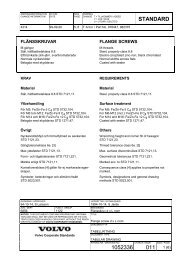
<strong>Installation</strong> <strong>and</strong> <strong>Adjustment</strong> <strong>Guide</strong> <strong>for</strong> SeBCON <strong>II</strong>:<br />
<strong>Boost</strong>: + <strong>more</strong> boost - less boost<br />
Overboost: + <strong>more</strong> boost - less boost<br />
Max-Load: + higher threshold - lower threshold<br />
RPM: + lower start rpm - higher start rpm<br />
Frequency: + higher frequency - lower frequency<br />
Delay: + less delay - <strong>more</strong> delay<br />
Gain: + <strong>more</strong> gain - less gain<br />
Status LEDs:<br />
Online: SeBCON is activated<br />
<strong>Boost</strong>: SeBCON provides the Solenoid with an signal<br />
Overboost: Overboost mode is activ<br />
Max-Load: Threshold was reached <strong>and</strong> SeBCON lowers the boost<br />
Knocking: SeBCON get’s an knocksignal <strong>and</strong> lowers the boost<br />
Potentiometers:<br />
<strong>Boost</strong>: <strong>Boost</strong> adjustment (RPM <strong>and</strong>/or Throttle mode activated, not in Auto mode)<br />
Overboost: Overboost adjustment (Throttle <strong>and</strong> Overboost mode activated)<br />
Max-Load: Threshold adjustment<br />
RPM: RPM adjustment (at which rpm the RPM or the Auto mode will be activated)<br />
Frequency: Solenoid frequency adjustable <strong>for</strong> different types of solenoids (default =10Hz)<br />
Delay: <strong>Boost</strong>-Delay 0.3-1.5 seconds, to minimize boost-spikes <strong>and</strong> to regulate fluctuations<br />
Gain: <strong>Boost</strong> level adjustment in Auto-mode<br />
Switches:<br />
Overboost: activates the Overboost mode (Throttle must be activated)<br />
Throttle: activates the <strong>Boost</strong> buildup with a simple throttle-switch (see signal discription)<br />
RPM: activates the <strong>Boost</strong> buildup at a specified rpm<br />
Auto: activates the Auto boost mode (RPM should be disabled when Auto is activ)<br />
- Load signal must be supplied to activate the Auto mode<br />
Frequency:<br />
With the Frequency-Poti it’s possible to adjust the Solenoids frequency. Most Solenoids like a<br />
frequency from round about 15-30Hz. If you are not sure, leave this poti untouched. With a<br />
wrong adjusted rate you will get less boost or a trimmed working-range because the Solenoid<br />
can not h<strong>and</strong>le a wrong rate.<br />
Important: The Solenoid frequency is adjusted to 30Hz by default.<br />
You can order SeBCON with your favorite frequency in case you have not the ability to adjust<br />
SeBCON yourself. The adjustment range is from 5Hz to 60Hz.
Discription of the 5 big separate cables:<br />
Power:<br />
Red: +12Volt (please use a fuse with at least 1Amp., max. 5Amp.)<br />
Black: Ground (use at least cable with 1.5mm2)<br />
Solenoid:<br />
Blue: Solenoid (use at least cable with 1.5mm2)<br />
- The 2nd cable of the Solenoid must be on +12Volt<br />
- The maximum current which SeBCON can h<strong>and</strong>le: 10 Ampere<br />
Ignition coil:<br />
Green/Yellow: KL 15, ignition +12Volt (brings SeBCON online, the Online LED should flash)<br />
Brown: KL 1, ignition coil (RPM signal)<br />
Discription of the 8 small separate cables:<br />
Brown: Throttle signal<br />
Brown/White: Knock signal<br />
Orange: Load signal<br />
Orange/White: Max-Load signal<br />
Blue/White: Ground<br />
Optional external boost regulator (Potentiometer):<br />
Blue: middle<br />
Green: left<br />
Green/White: right<br />
Discription of the signals:<br />
Throttle signal:<br />
The throttle signal must be a ground signal. The Throttle-Switch <strong>and</strong> the RPM or the<br />
Overboost-Switch has to be activated (<strong>and</strong> you have to adjust a minimum amount of boost<br />
with the <strong>Boost</strong> or Overboost Poti), then the <strong>Boost</strong> or the Overboost LED should flash.<br />
Load signal:<br />
Signal between 0 <strong>and</strong> 12Volt, ~2Volt is 10% <strong>and</strong> ~10Volt is 100% Solenoid pulse wide. If the<br />
signal is duly <strong>and</strong> you have activated the Auto-function, the <strong>Boost</strong> LED should flash.<br />
Knock signal:<br />
The knock signal must be either a ground signal (less than 0.7Volt) or a +12Volt signal (greater<br />
than 10Volt). If the signal is duly, the Knocking LED should flash <strong>and</strong> you should not have any<br />
additional boost over stock.<br />
Max-Load signal:<br />
Signal must be between >0 <strong>and</strong> 12 Volt. The threshold is adjustable with the Max-Load Poti. Give<br />
the signal you wish to use on the Max-Load input <strong>and</strong> adjust the Poti in that way, that the Max-<br />
Load LED just begins flashs, this is the threshold on which SeBCON begins to lower the boost.<br />
KL 1, ignition coil (RPM signal):<br />
Activates the Auto <strong>and</strong>/or the RPM function at the adjusted threshold (rpm).
How to start:<br />
In most cases there are two possible modes, the ’mechanical’ way <strong>for</strong> a engine with carburator<br />
<strong>and</strong> a mechanical ingnition distributor <strong>and</strong> the ’electronical’ way <strong>for</strong> a engine with ECU <strong>and</strong> ICU.<br />
I will discribe these two ways, but there are other possible options, just let you inspire <strong>and</strong> think<br />
about the possibilitys with the Input-signals.<br />
Be<strong>for</strong>e we start, i assume that you have already connected SeBCON to the power net, provide<br />
the red cable with +12Volt (dont <strong>for</strong>get the fuse), the black cable with Ground <strong>and</strong> the Solenoid<br />
should also be correct connected with the blue cable at one cable, the other cable from the<br />
Solenoid must go to +12Volt (it’s not a bad idea, the use a 10Amp. fuse in the +12 connection).<br />
We also need Kl. 1 <strong>and</strong> Kl. 15 from the ignition coil, the green/yellow cable goes to Kl. 15<br />
ignition <strong>and</strong> the brown cable goes to Kl. 1, the RPM signal. If all is fine, switch on the ignition <strong>and</strong><br />
the Online LED should flash. If not, we have a major problem which must be solved be<strong>for</strong>e we<br />
proceed.<br />
1. ’Mechanical Stage’:<br />
SeBCON is now already connected to buildup boost. You can just switch on the RPM-Switch,<br />
increase boost with a few turns on the <strong>Boost</strong>-Poti (clockwise), start the engine <strong>and</strong> hold rpm at<br />
e.g. 2500rpm, then turn the RPM-Poti (clockwise) until the <strong>Boost</strong> LED begins to flash. Now you<br />
can adjust the boost with the <strong>Boost</strong>-Poti by driving in town <strong>and</strong> have a look at the hopefully<br />
installed <strong>Boost</strong>-Gauge.<br />
When you are familiar with this function, you can connect a full-throttle switch to the Throttle<br />
cable (brown cable from the small ones) <strong>and</strong> activate the Throttle-Switch. Now you will get the<br />
previously adjusted boost level as soon as you kick down the gas pedal or when the engines<br />
exceeds the adjusted rpm.<br />
The next step is to activate the Overboost-Switch. This switch needs a activated Throttle-Switch<br />
because his function bases on the throttle switch. The function is the same as be<strong>for</strong>e with the<br />
difference, that you can bring the engine into the Overboost, which will be adjusted with the<br />
Overboost-Poti.<br />
It’s up to you, which switch you use to bring the engine into the Overboost mode, it can also be<br />
a push-button on the steering gear instead of a full throttle switch.
2. ‘Electronical Stage’:<br />
Let’s start with SeBCON’s main funtion, the Auto-mode. To activate the Auto-mode, SeBCON<br />
needs a load signal at the Load input. The Load function is bound to the RPM function, this<br />
means, that the Auto mode ist active when the rpm exceeds the adjusted threshold.<br />
(Note that the RPM-Switch is OFF while using the rpm function in Auto-mode)<br />
To adjust the rpm in the Auto mode, start the engine <strong>and</strong> hold rpm at e.g. 2500rpm, then turn<br />
the RPM-Poti (clockwise) until the <strong>Boost</strong> LED begins to flash. The amount on boost depends on<br />
the signal which comes through the Load input. Drive around in town <strong>and</strong> have a look what’s the<br />
max-boost, you will get the max-boost only on heavy engine load.<br />
If the boost is not high enough, it’s possible to raise boost with the GAIN-Poti. The Gain-Poti is<br />
<strong>for</strong> the case if the Load signal is not high enough, e.g. when the signal comes from an Air-Mass-<br />
Meter. If the Load signal which you use is in the range from 2-10Volt, the GAIN should be set to<br />
the minimum (GAIN=1), if the signal ist not high enough, like from the AMM, than a higher Gain<br />
is indicated. So, in Auto mode the boost height will be adjusted automatically or if necessary<br />
increased with the GAIN-Poti.<br />
Additional to the Auto-mode it’s possible to use all the other modes stated in the ’Mechanical<br />
Stage’, means <strong>Boost</strong> or Overboost via Throttle or RPM. My advice is, to combine the Auto mode<br />
which should be set to around 3000 rpm with the Full Throttle Overboost mode. This gives you a<br />
engine which runs under low throttle with factory settings, under normal load with a good<br />
amount of boost <strong>and</strong> if you wan’t power, you will get it in <strong>for</strong>m of the Overboost by hitting down<br />
the gas pedal.<br />
Delay:<br />
The Delay function is there to minimize boost spiking. The delay can be adjusted from ~0.3 sec.<br />
up to 2 sec., means that this is the timedelay from stock to max. boost <strong>and</strong> vice versa.<br />
Max-Load:<br />
The Max-Load function needs a proper signal between 1 -12Volt to work, <strong>and</strong> with the Max-Load-<br />
Poti it’s possible to adjust which voltage is the threshold. If the signal exceeds the threshold,<br />
SeBCON begins to lower the boost until the signal is under the threshold, than the boost will<br />
increase again up to the threshold <strong>and</strong> down under the threshold.<br />
What’s the point? I will explain it with a example. Some cars have a so called ‘Fuel-Cut’ build into<br />
the ECUs’ software. The Fuel-Cut occurs e.g. when the signal from the AMM exceeds 5.1Volt. If<br />
you give this signal onto the Max-Load input <strong>and</strong> adjust the Max-Load input to be activated by<br />
5.0Volt, SeBCON lowers the boost if the AMM sends a signal greater than 5.0Volt. This reduction<br />
of the boost will cause a lower Voltage on the AMM (less boost) <strong>and</strong> prevents the engine be<strong>for</strong>e<br />
to run into the Fuel-Cut.<br />
Since this function is a ‘closed loop’ function, SebCON gives you exactly the amount of boost<br />
which is currently possible under the circumstances. So the engine can run at WOT at the ECU’s<br />
edge.<br />
Knocking:<br />
The Knock function works in exactly the same way as the Max-Load function, but with a different<br />
input signal. On regular operation the Knock-Input should be potential-free or between a voltage<br />
from 1 to 9Volt, voltages less than 0.7Volt or greater than 10Volt will activate the Knock<br />
function. As knock detector it’s possible to use third party products or if available, the abilitys of<br />
the present ICU.
Optional external Potentiometer:<br />
With the external Poti it’s possible to overwrite the internal boost settings <strong>and</strong> increase the boost<br />
as far as the internal settings are not already at the maximum boost. After use you should not<br />
<strong>for</strong>get to set the Poti to minimum or switch it off, otherwise SeBCON can not manage the boost<br />
accordingly.<br />
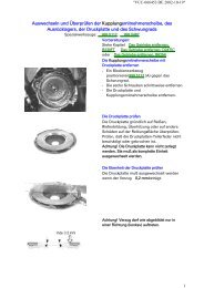
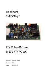
Connection scheme:
This site is only <strong>for</strong> Volvo B230FT’s of interest<br />
Signals LH2.4 <strong>and</strong> EZ116K:<br />
AMM Signal: AMM Pin3 cable BL/R or LH2.4 PIN7<br />
Knocksignal: LH2.4 PIN28 or EZ116K PIN4, or con. right wheel house tower, POS.1, R/G cable<br />
Throttle-Signal: Connector right wheel house tower, POS.7, R/W cable<br />
BL/R = Blue/Red<br />
R/G = Red/Grey<br />
R/W = Red/White<br />
Signals LH2.2 <strong>and</strong> EZ117K:<br />
AMM Signal: Pin7 ECU<br />
Knocksignal: Pin15 EZK (only Turbo EZK’s !)<br />
Throttle-Signal: -<br />
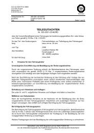
DEUTSCH: Signale am Volvo 7/9’er B230FT LH2.4:<br />
Schwarz = Masse<br />
Rot = Dauerplus Batterie o.a.<br />
Blau = Solenoid<br />
Zweites Kabel vom Solenoid = +12V mit Sicherung (5-10 Amp.), Dauerplus oder Zuendungsplus<br />
Gruen/Gelbe = +12V Zuendungsplus<br />
Braun = Zuendspule, Klemme1 Drehzahlsignal, Zuendspule ist am Anschluss mit Kl.1 beschriftet<br />
D = Vollast-Signal: Konnektor rechter Federbeindom, 2 Kabelverbinder POS.7, R/W Kabel, oder<br />
direkt am Drosselklappenschalter, der Kontakt mit dem Massesignal bei Volllast<br />
F = Klopfsignal, LH2.4 Pin28<br />
G = Lastsignal, LH2.4 Pin7<br />
H = Maxload, LH2.4 Pin7<br />
G+H zusammen an LH 2.4 Pin7 !!<br />
Signals at Volvo 7/9’er B230FT LH2.4:<br />
Black = ground<br />
Red = permanent positive, e.g. Batterie<br />
Blue = Solenoid<br />
Second cable from the solenoid = +12V with fuse, permanent positive or ignition positive<br />
Green/Yellow = +12V ignition positive<br />
Brown = ignition coil, Kl.1 rpm-signal, there is a mark KL.1 on the ignition coil<br />
D = throttle-signal: Connector right wheel house tower, POS.7, R/W cable<br />
F = knock signal, LH2.4 Pin28<br />
G = Load signal, LH2.4 Pin7<br />
H = Maxload, LH2.4 Pin7
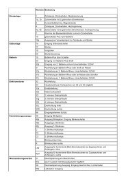
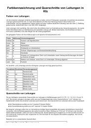
Example boost diagram:
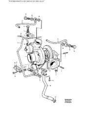
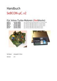
Solenoids:<br />
Pierburg: 7.21559.00 12V DC 0032 / Volvo Part: 3517757 -<br />
from the original Volvo Turbo+Kit (B204FT <strong>and</strong> B230FT)<br />
2-Port Bleed-Valve<br />
2-Port Solenoids use a "T" connector to plug<br />
into the boost control line. Top-boost is slightly<br />
weak, maybe problems with spiking (only<br />
when boost is set to <strong>more</strong> than ~14psi).<br />
Pierburg 7.22240.13.0 12V / Volvo Part: 30670448<br />
from Volvo S/C/V70, S60, S80 <strong>and</strong> XC90 Turbo Models<br />
3-Port Valve (preffered device)<br />
3-Port Solenoids allows completely to interrupt<br />
the boost signal to the wastegate.<br />
Markers on the valve:<br />
red (top): turbocharger<br />
blue (middle): drain<br />
yellow (bottom): wastegate<br />
The regulated Airflow from this Solenoid is<br />
~50% because there is all the time an amount<br />
of pressure which goes to the wastegate.<br />
If the Solenoid is off, 100% pressure goes to<br />
the WG, if the Solenoid is fully open it may be<br />
~50% pressure which goes to the WG.<br />
In other words, you can regulate 50% control<br />
pressure with 100% pulse-width. There<strong>for</strong>e a<br />
very fine adjustment is possible, but the top<br />
boost is not as high as with a real 3-port valve.<br />
To increase top boost i have figured out, that<br />
the line to the WG must be restricted to 2mm<br />
diameter, then top boost goes up 4-5psi, it’s<br />
still very good adjustable then.<br />
For pressure up to 1Bar/14.5psi<br />
(with mod. 18-20psi)<br />
Markers on the valve:<br />
red: turbocharger<br />
yellow: wastegate<br />
blue: drain<br />
The regulated Airflow from this Solenoid is<br />
100%. If the valve is closed, all the pressure<br />
goes to the wastegate, if fully open, the<br />
wastegate is fully connected to the drain. So<br />
you can regulate 100% control pressure with<br />
100% pulse-width.<br />
In other words, you can regulate <strong>more</strong> control<br />
pressure with the same pulse-width, the boost<br />
which can be adjusted is much higher then<br />
with the above device, but it’s not as smooth<br />
adjustable as with the above 2-port bleed<br />
valve.<br />
For pressures <strong>more</strong> than 1Bar/14.5psi
iPd Heavy Duty Turbo Control Valve 3E1010 HD<br />
3-Port Valve<br />
3-Port Solenoids allows completely to interrupt<br />
the boost signal to the wastegate.<br />
red: turbocharger<br />
yellow: wastegate<br />
blue: drain<br />
The regulated Airflow from this Solenoid is<br />
100%. If the valve is closed, all the pressure<br />
goes to the wastegate, if fully open, all the<br />
pressure goes to the drain. So you can<br />
regulate 100% Mass with 100% pulse-width.<br />
To get this device better adjustable, it’s a<br />
good idea to restrict the input line (red)<br />
to 1-1.5mm diameter.<br />
Other Solenoids:<br />
-<br />
http://www.stonis-world.net/docs/pierburg_electric_valves.pdf<br />
-<br />
3-Port Valve:<br />
GM Typhoon Solenoid - Part Nr. #1997152 #http://www.gmpartsdirect.com/<br />
http://www.tarmacwolf.org/dokuwiki/doku.php?id=3-port_boost_solenoid<br />
http://<strong>for</strong>ums.turbobricks.com/showthread.php?t=80599<br />
-<br />
3-Port Valve:<br />
Volvo C70 S40 S60 S70 S80 V40 V70<br />
Pierburg 7.22240.13.0<br />
Up to 2001: Volvo Part Nr. 9473212<br />
From 2002: Volvo Part Nr. 30670448<br />
-<br />
3-Port Valve:<br />
Volvo V70:<br />
Pierburg 7.28197.01 / Volvo 9465528<br />
Pierburg 7.28197.03 / Volvo 30670449<br />
-<br />
iPd Turbo Controller Valve (#3E1010 HD)<br />
-<br />
Perrin EBCS Electronic <strong>Boost</strong> Control Solenoid (SKU: #ASM-INT-720)