Single Phase AC Induction Squirrel Cage Motors - Aerovent
Single Phase AC Induction Squirrel Cage Motors - Aerovent Single Phase AC Induction Squirrel Cage Motors - Aerovent
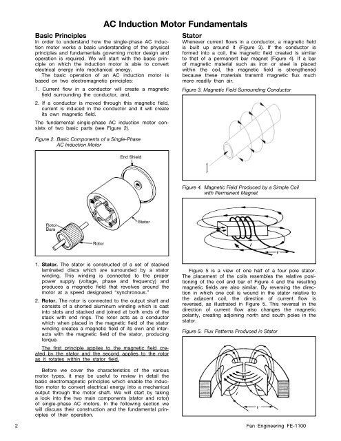
Basic PrinciplesIn order to understand how the single-phase AC inductionmotor works a basic understanding of the physicalprinciples and fundamentals governing motor design andoperation is required. We will start with the basic principleon which the induction motor is able to convertelectrical energy into mechanical energy.The basic operation of an AC induction motor isbased on two electromagnetic principles:1. Current flow in a conductor will create a magneticfield surrounding the conductor, and,2. If a conductor is moved through this magnetic field,current is induced in the conductor and it will createits own magnetic field.The fundamental single-phase AC induction motor consistsof two basic parts (see Figure 2).Figure 2. Basic Components of a Single-PhaseAC Induction MotorAC Induction Motor FundamentalsStatorWhenever current flows in a conductor, a magnetic fieldis built up around it (Figure 3). If the conductor isformed into a coil, the magnetic field created is similarto that of a permanent bar magnet (Figure 4). If a barof magnetic material such as iron or steel is placedwithin the coil, the magnetic field is strengthenedbecause these materials transmit magnetic flux muchmore readily than air.Figure 3. Magnetic Field Surrounding ConductorFigure 4. Magnetic Field Produced by a Simple Coilwith Permanent Magnet1. Stator. The stator is constructed of a set of stackedlaminated discs which are surrounded by a statorwinding. This winding is connected to the properpower supply (voltage, phase and frequency) andproduces a magnetic field that revolves around themotor at a speed designated “synchronous.”2. Rotor. The rotor is connected to the output shaft andconsists of a shorted aluminum winding which is castinto slots and stacked and joined at both ends of thestack with end rings. The rotor acts as a conductorwhich when placed in the magnetic field of the statorwinding creates a magnetic field of its own and interactswith the magnetic field of the stator, producingtorque.The first principle applies to the magnetic field createdby the stator and the second applies to the rotoras it rotates within the stator field.Figure 5 is a view of one half of a four pole stator.The placement of the coils resembles the relative positioningof the coil and bar of Figure 4 and the resultingmagnetic fields are also similar. By reversing the directionin which one coil is wound in the stator relative tothe adjacent coil, the direction of current flow isreversed, as illustrated in Figure 5. This reversal in thedirection of current flow also changes the magneticpolarity, creating adjoining north and south poles in thestator.Figure 5. Flux Patterns Produced in StatorBefore we cover the characteristics of the variousmotor types, it may be useful to review in detail thebasic electromagnetic principles which enable the inductionmotor to convert electrical energy into a mechanicaloutput through the motor shaft. We will start by takinga look into the two main components (stator and rotor)of single-phase AC motors. In the following section wewill discuss their construction and the fundamental principlesof their operation.2 Fan Engineering FE-1100
In the completed stator, a magnetic field is createdhaving alternating north and south poles. The number ofmagnetic poles in the stator, together with the AC linefrequency, determines the speed at which the motor willoperate.RotorIf a conductor is moved between the faces of a horseshoemagnet (Figure 6), a voltage is induced in thatconductor, and if the conductor forms part of a completedcircuit, current will flow. The action which producesthis voltage and current is the cutting of themagnetic field (called lines of magnetic flux) by the conductor.This current flow within the conductor will in turnproduce a magnetic field, as seen in Figures 3 and 6.The interaction of these two magnetic fields produces amechanical force on the wire which is the basis for theproduction of torque.Figure 6. Elements of Motor ActionV dcDirection ofOpposingForceDirectionof MotionIn an induction motor, the single conductor of theprevious example is replaced by the rotor winding. Insmall motors, this winding is normally of cast aluminumand consists of multiple conductors, or rotor bars, castinto the slots in the rotor core and joined at both endsof the stack with end rings. The resulting rotor windingcircuit is illustrated in Figure 7, and as can be seen fromthis figure, the name has been designated as “squirrelcage rotors.”Figure 7. Representation of Voltage-CurrentPaths (and Strengths) in Squirrel Cage RotorSNis passing through at that time. Because the strength ofthe stator field varies around its circumference, beingstrongest at each pole, the voltages and currentsinduced in the rotor bars will also vary around the rotor.Figure 7 illustrates the directions and magnitudes of atypical rotor bar current pattern. The magnetic field builtup around each bar reacts with the stator flux, exertinga force on each bar in the same manner as previouslydescribed in the example of the horseshoe magnet andsimple conductor. The sum total of all forces acting onall rotor bars is the output torque of the motor.Magnetic Field for Single-Phase MotorsIn order for the rotor to move, the stator must producea rotating magnetic field. With a single source of ACvoltage connected to a single winding, this is not possible.A stationary flux field is created which pulsates instrength as the AC voltage varies, but it does not rotate.This pulsating field strength is what simulates a rotatingfield and gives the rotor its rotation. If a stationary rotoris placed in this single-phase stator field, it will notrotate, but if the rotor is spun by hand, it will pick upspeed and run. The single-phase motor will run (in eitherdirection) if started by hand, but it will not develop anystarting torque as illustrated in Figure 8.Motor Starting for Single-Phase MotorsWhat is needed is a second (start) winding, with currentsout of phase with the original (main) winding, to producea net rotating magnetic field. The various single-phasemotor designs differ in the type of secondary (start)winding employed. These start windings, which togetherwith other components such as capacitors, relays andcentrifugal switches, make up the starting circuit, providevarying effects on motor starting and running characteristics.Figure 8. Speed-Torque Characteristics of Single-Phase,Single Main Winding Only MotorPercent Synchronous Speed100806040200 0 100 200 300 400 500Percent Full-Load TorqueAs a rotor turns, the rotor bars cut through the fluxlines of the stator magnetic field and voltages and currentsare induced in each bar. The magnitude of thevoltage and current in a given bar will depend on themagnetic density of the stator field which the rotor barTwo basic mathematical models best reveal twoimportant facts about single-phase motors:1. The performance characteristics of single-phasemotors can approach, but will not exceed that of thetwo-phase polyphase motors.2. The torque produced at a given RPM is not constant,but pulsates at twice the line frequency around amedian value. These torque pulsations are inherent to3 Fan Engineering FE-1100
- Page 4 and 5: all single-phase motors and can cau
- Page 6 and 7: Capacitor-Start Motors (CSIR)The ne
- Page 8 and 9: Capacitor Start-Capacitor Run Motor
- Page 10: Single-phase AC motors are not all
Basic PrinciplesIn order to understand how the single-phase <strong>AC</strong> inductionmotor works a basic understanding of the physicalprinciples and fundamentals governing motor design andoperation is required. We will start with the basic principleon which the induction motor is able to convertelectrical energy into mechanical energy.The basic operation of an <strong>AC</strong> induction motor isbased on two electromagnetic principles:1. Current flow in a conductor will create a magneticfield surrounding the conductor, and,2. If a conductor is moved through this magnetic field,current is induced in the conductor and it will createits own magnetic field.The fundamental single-phase <strong>AC</strong> induction motor consistsof two basic parts (see Figure 2).Figure 2. Basic Components of a <strong>Single</strong>-<strong>Phase</strong><strong>AC</strong> <strong>Induction</strong> Motor<strong>AC</strong> <strong>Induction</strong> Motor FundamentalsStatorWhenever current flows in a conductor, a magnetic fieldis built up around it (Figure 3). If the conductor isformed into a coil, the magnetic field created is similarto that of a permanent bar magnet (Figure 4). If a barof magnetic material such as iron or steel is placedwithin the coil, the magnetic field is strengthenedbecause these materials transmit magnetic flux muchmore readily than air.Figure 3. Magnetic Field Surrounding ConductorFigure 4. Magnetic Field Produced by a Simple Coilwith Permanent Magnet1. Stator. The stator is constructed of a set of stackedlaminated discs which are surrounded by a statorwinding. This winding is connected to the properpower supply (voltage, phase and frequency) andproduces a magnetic field that revolves around themotor at a speed designated “synchronous.”2. Rotor. The rotor is connected to the output shaft andconsists of a shorted aluminum winding which is castinto slots and stacked and joined at both ends of thestack with end rings. The rotor acts as a conductorwhich when placed in the magnetic field of the statorwinding creates a magnetic field of its own and interactswith the magnetic field of the stator, producingtorque.The first principle applies to the magnetic field createdby the stator and the second applies to the rotoras it rotates within the stator field.Figure 5 is a view of one half of a four pole stator.The placement of the coils resembles the relative positioningof the coil and bar of Figure 4 and the resultingmagnetic fields are also similar. By reversing the directionin which one coil is wound in the stator relative tothe adjacent coil, the direction of current flow isreversed, as illustrated in Figure 5. This reversal in thedirection of current flow also changes the magneticpolarity, creating adjoining north and south poles in thestator.Figure 5. Flux Patterns Produced in StatorBefore we cover the characteristics of the variousmotor types, it may be useful to review in detail thebasic electromagnetic principles which enable the inductionmotor to convert electrical energy into a mechanicaloutput through the motor shaft. We will start by takinga look into the two main components (stator and rotor)of single-phase <strong>AC</strong> motors. In the following section wewill discuss their construction and the fundamental principlesof their operation.2 Fan Engineering FE-1100


