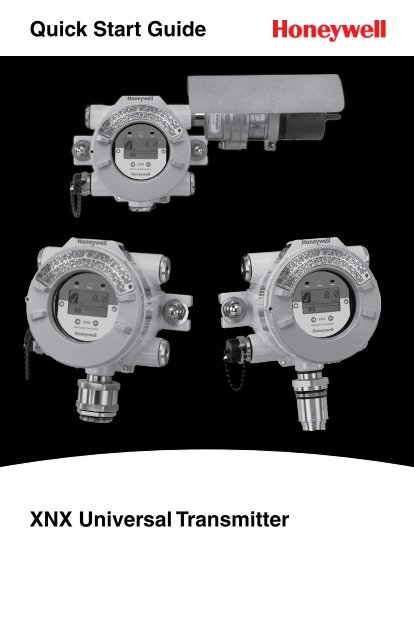
Quick Start Guide XNX Universal Transmitter - Merkantile
Quick Start Guide XNX Universal Transmitter - Merkantile
Quick Start Guide XNX Universal Transmitter - Merkantile
- No tags were found...
Create successful ePaper yourself
Turn your PDF publications into a flip-book with our unique Google optimized e-Paper software.
WARNINGS»» The <strong>XNX</strong> <strong>Universal</strong> <strong>Transmitter</strong> is certified and designed for installation and useworldwide in hazardous areas.»» Installation must be in accordance with the recognized standards of the appropriateauthority in the country concerned.»» Access to the interior of the detector, when carrying out any work, must only be conductedby trained personnel.»» Before carrying out any work, ensure local regulations and site procedures are followed.Appropriate standards must be followed to maintain the overall certification of the detector.»» To reduce the risk of ignition of hazardous atmosphere, disconnect the equipment fromthe supply circuit before opening the detector enclosure. Keep assembly tightly closedduring operation.»» Never open the <strong>XNX</strong> enclosure under power unless the area is known to be non hazardous.»» The detector must be earthed/grounded for Intrinsic Safety, electrical safety and to limitthe effects of radio frequency interference. An earth/ground point is provided insideand outside the unit. The internal grounding shall be used as the primary equipmentground. The external terminal is only a supplemental bonding connection where localauthorities permit or require such a connection.»» Take care when handling EC sensor cells as they may contain corrosive solutions.»» Do not tamper or in any way disassemble the sensor cells.»» Do not expose to temperatures outside the recommended range.»» Do not expose sensor to organic solvents or flammable liquids.»» At the end of their working life, sensors must be disposed of in an environmentallysafe manner. Disposal should be according to local waste management requirementsand environmental legislation.»» Alternatively, sensors may be securely packaged and returned to Honeywell Analyticsclearly marked for environmental disposal.»» Electrochemical cells should NOT be incinerated as they may emit toxic fumes.Hazardous Locations Installation Requirements (UL/CSA)»» To reduce the risk of ignition of hazardous atmospheres, conduit runs must have a pourgland installed within 18 inches (457mm) of enclosure.»» All ¾ inch NPT conduit, stopping plugs and adapters must be installed with 5 ¼ threads(minimum) engaged to Maintain Explosion Proof rating.»» The <strong>XNX</strong> Cover Assembly must be fully seated to enclosure 9 threads (minimum) tomaintain Explosion Proof rating.»» Stopping Plugs supplied (Honeywell Part Number 1226-0258) are approved for useONLY with the <strong>XNX</strong> <strong>Universal</strong> <strong>Transmitter</strong>.»» For units fitted with the Optional Relay Module: Relay Contact Ratings are 250 VAC5A, 24 VDC 5A Resistive Loads Only.»»Use copper conductors only, 60/75°C, terminal block screws should be tightened to4.5 Lb/in maximum.»» Reference <strong>XNX</strong> Control Drawing 1226E0402 for additional information regarding ISfunction (Local HART and EC Personality).Hazardous Locations Installation Requirements (ATEX)»» Read and understand this manual before installation and use.»» Use only Certified M25 cable glands for installation.»» Shielded armoured cable is required for CE compliance.<strong>XNX</strong> <strong>Universal</strong> <strong>Transmitter</strong> <strong>Quick</strong> <strong>Start</strong> <strong>Guide</strong> 3
Table of Contents1 Mounting and Location of Detectors71.1 Mounting the <strong>XNX</strong> <strong>Universal</strong> <strong>Transmitter</strong>72 Wiring the <strong>XNX</strong>102.1 General Wiring Considerations102.2 Distance Considerations for Installation ............................112.3 POD Connections142.4 4-20mA Output, Common Connections and Power142.5 Terminal Block Connections162.6 EC Personality Wiring172.6.1 <strong>XNX</strong> Electrochemical (EC) Sensor Installation ..............192.7 mV Personality Wiring212.8 IR Personality Wiring252.8.1 Connecting a Searchpoint Optima Plus or SearchlineExcel ..............................................................................262.8.2 Connecting Generic mA Device .....................................293 Options323.1 Local HART ® Handheld323.2 Relays33® 343.3 Modbus4 Powering the <strong>XNX</strong> for the First Time354.1 <strong>XNX</strong> Units Configured for EC, mV, and IR (except SearchlineExcel) 354.2 <strong>XNX</strong> IR Units Configured for Searchline Excel364.3 Configuring the <strong>XNX</strong> <strong>Universal</strong> <strong>Transmitter</strong>385 The <strong>XNX</strong> Front Panel395.1 Controls and Navigation395.2 The General Status Screen395.3 Entering the Menu Structure415.4 Displaying <strong>Transmitter</strong> Information426 Gas Calibration Menu426.1 Calibration436.1.1 Calibration Procedure ....................................................436.1.2 Zero and Span Calibration for <strong>XNX</strong> EC Sensors ...........456.1.3 Zero and Span Calibration of <strong>XNX</strong> EC Hydrogen Sulfide (H 2S)Sensors ........................................................................................... 456.1.4 <strong>XNX</strong> EC Sensor Operational Life ...................................466.1.5 Zero and Span Calibration for MPD Sensors ............................466.1.6 Cross Calibration procedure for MPD-CB1 ....................486.1.7 Calibrating the 705/705HT .............................................506.1.8 Calibrating the Sensepoint/Sensepoint HT ....................504<strong>XNX</strong> <strong>Universal</strong> <strong>Transmitter</strong> <strong>Quick</strong> <strong>Start</strong> <strong>Guide</strong>
Table of Contents (cont’d)6.1.9 Calibrating the Searchline Excel and Searchpoint OptimaPlus ................................................................................506.2 Functional Gas Testing (Bump Test)508 <strong>XNX</strong> Catalytic Bead and IR Replacement Sensor Cartridges539 Warning Messages5310 Fault Messages5711 Informational Messages6712 Control Drawings6913 <strong>XNX</strong> Labels73UL Certification Labels73ATEX Certification Label73<strong>XNX</strong> <strong>Universal</strong> <strong>Transmitter</strong> <strong>Quick</strong> <strong>Start</strong> <strong>Guide</strong> 5
6<strong>XNX</strong> <strong>Universal</strong> <strong>Transmitter</strong> <strong>Quick</strong> <strong>Start</strong> <strong>Guide</strong>
1 Mounting and Location of DetectorsCautionThe location of the transmitters and sensors should be made in accordance withany relevant local and national legislation, standards or codes of practice. Alwaysreplace detectors with a detector of the same type. The detector should be mountedwhere the gas is most likely to be present. The following points should be notedwhen locating gas detectors.• Consider the possible damage caused by natural events e.g. rain or floodingwhen locating detectors.• Consider ease of access for functional testing and servicing.• Consider how escaping gas may behave due to natural or forced aircurrents.NoteThe placement of detectors should be determined following the adviceof experts having specialist knowledge of gas dispersion, experts havingknowledge of the process plant system and equipment involved, safety andengineering personnel. The agreement reached on the location of detectorsshould be recorded.1.1 Mounting the <strong>XNX</strong> <strong>Universal</strong> <strong>Transmitter</strong>The <strong>XNX</strong> <strong>Universal</strong> <strong>Transmitter</strong> can be mounted in a number of different methodsusing the integral mounting tabs.Using the mounting tabs, the <strong>XNX</strong> can be attached to:• flat wall surface®• UnistrutWith the optional Pipe Mount kit, the <strong>XNX</strong> can be mounted to pipe of diameter 2 to6 in (50 to 150mm).A ceiling mount bracket kit (1226A0358) is also available.Integral Mounting LugsFigure 1. Integral Mounting Lugs and Optional Pipe and Ceiling Mounts<strong>XNX</strong> <strong>Universal</strong> <strong>Transmitter</strong> <strong>Quick</strong> <strong>Start</strong> <strong>Guide</strong> 7
7.75"196.85 mm6.00"15.4 mm5.6"124.24 mm4.48"113.8 mm2.054"52.18mm0.625"15.88mm0.55"14.35 mm1.67"42.41 mm1.2"31.75mm1.768"44.90 mm1.768"44.90 mm0.945"24mm3.176"80.67 mm6.138"158.75mmAllow 11" 280mmfor Maint./Service<strong>XNX</strong> withSearchpoint Optima Plus6"152 mmw/sun shield4"101.6mmAllow12"305mmForMaintenanceService<strong>XNX</strong> with MPD or Local EC SensorFigure 2. <strong>XNX</strong> <strong>Universal</strong> <strong>Transmitter</strong> Mounting Dimensions and ClearancesWarningWhen the <strong>XNX</strong> is equipped with the optional Remote Mount Kit, the remote sensorMUST be securely mounted to a fixed position. The Remote Sensor Kit is not intendedto be used as a hand-held detector.8<strong>XNX</strong> <strong>Universal</strong> <strong>Transmitter</strong> <strong>Quick</strong> <strong>Start</strong> <strong>Guide</strong>
The <strong>XNX</strong> is configured with 5 cable/conduit entries built into the housing for wiring andmounting sensors. Figure 3 provides the guidelines to proper installation of the <strong>XNX</strong>.AENoteWhile relay wiring can use anyavailable cable/conduit entry inthe <strong>XNX</strong> enclosure, do not use thesame cable/conduit entry for bothrelay reset and relay signal lines toavoid electrical noise.*DBCOptionLocal HART ® OptionMPD, 705 Series, Sensepoint SeriesCatalytic Bead SensorSearchpoint Optima PlusSearchline ExcelRemote Sensor Connection (except EC )Searchpoint Optima Plus - RemoteModbus ®RelaysPower* Limited access due toIS barrier if equipped withelectrochemical cell.PositionBCCA or ETypically CAny remainingAny remainingAny remainingAny remainingAny remainingFigure 3. <strong>XNX</strong> <strong>Universal</strong> <strong>Transmitter</strong> Cable/Conduit Entry AssignmentsIntegral Mounting LugsFigure 4. Integral Mounting Lugs and Optional Pipe and Ceiling Mounts<strong>XNX</strong> <strong>Universal</strong> <strong>Transmitter</strong> <strong>Quick</strong> <strong>Start</strong> <strong>Guide</strong> 9
2 Wiring the <strong>XNX</strong>Personality circuit boards determine the <strong>XNX</strong> behavior based on the sensor typeattached to the <strong>XNX</strong> interface.The table below defines the three <strong>XNX</strong> transmitter configurations and the sensorseach support.<strong>XNX</strong> IR Personality<strong>XNX</strong> EC PersonalitySearchline ExcelSearchpoint Optima Plus Local/RemoteGeneric mA Sensors<strong>XNX</strong> EC Sensor<strong>XNX</strong> EC Sensor Remote Mount Kit<strong>XNX</strong> mV Personality705 Local / Remote MPD Local (cat bead and IR) Sensepoint Local / Remote705HT Local / Remote MPD Remote Sensepoint PPM Local/RemoteSensepoint HT RemoteCautionBefore wiring the <strong>XNX</strong>, confirm the correct personality boards and options areinstalled.2.1 General Wiring ConsiderationsFor proper operation of the <strong>XNX</strong> <strong>Universal</strong> <strong>Transmitter</strong> and Sensor Technologies,consideration of wiring induced voltage drops, transient electrical noise and dissimilarEarth ground potentials is imperative in the design and installation of the system.Note:To maintain EMC integrity, wiring must be shielded by either an integral shieldor run through conduit or pipe. Shield should provide 90% coverage.LoadingWiring for DC Power, 4-20mA Signal, remote wiring to sensors must be sizedsufficiently to provide sufficient voltages for the line length and the loads that willbe used.IsolationIsolating power and signal carrying conductors is recommended.Circuit ProtectionSupply circuits must provide over current protection. Class 2 power supplies arerequired for 24 volt DC supply. Consider Inrush current in specifying any DC supply.Power supply range is 16 to 32 VDC for EC and mV versions, 18 to 32 VDC for10<strong>XNX</strong> <strong>Universal</strong> <strong>Transmitter</strong> <strong>Quick</strong> <strong>Start</strong> <strong>Guide</strong>
Searchpoint Optima Plus and Searchline Excel and 16 to 32 VDC dependent onthe limitations of device for the generic 4-20mA input.LoadsThe use of High Inrush or Inductive loads may affect the performance of the <strong>XNX</strong>.For best reliability use resistive loads only.2.2 Distance Considerations for InstallationTypes of InstallationsThere are three basic types of installation: a single transmitter; multiple transmittersconnected to a single power source; and multiple transmitters connected in a “daisychain”configuration.Power Source SelectionThe power requirements for different transmitter configurations are:• <strong>XNX</strong> EC (Toxic): 6.2 watts• <strong>XNX</strong> mV (Catalytic): 6.5 watts• <strong>XNX</strong> IR with Searchpoint Optima Plus: 9.7 watts• <strong>XNX</strong> IR with Searchline Excel: 13.2 wattsWire SelectionThe type of wire used for connections has an effect on the distance of theinstallation. This is because some of the voltage is lost in the wire on the way tothe transmitter.Single <strong>Transmitter</strong> DistancesFor installations that have dedicated wiring between the transmitter and the powersupply, use the following chart. These distances assume stranded wire is used.ORClass 2Power SupplyClass 2Power Supply<strong>XNX</strong> mV or ECWith Sensor<strong>XNX</strong> IR withSearchpoint Optima Plus<strong>XNX</strong> IR withSearchline ExcelSingle <strong>Transmitter</strong> Distances18 AWG[1.0 mm 2 ]1140 feet[347 meters]660 feet[201 meters]550 feet[168 meters]16 AWG[1.5 mm 2 ]1810 feet[551 meters]1060 feet[323 meters]890 feet[270 meters]14 AWG[2.0 mm 2 ]2890 feet[880 meters]1690 feet[515 meters]1410 feet[430 meters]12 AWG[3.5 mm 2 ]4620 feet[1408 meters]2690 feet[820 meters]2260 feet[690 meters]NoteIf multiple transmitters are using the same power supply, make sure thepower supply wattage rating is high enough to power all transmitterssimultaneously.<strong>XNX</strong> <strong>Universal</strong> <strong>Transmitter</strong> <strong>Quick</strong> <strong>Start</strong> <strong>Guide</strong> 11
“Daisy-Chained” <strong>Transmitter</strong> DistancesA few selected scenarios are presented here to provide a base to work from.<strong>Transmitter</strong> 1 <strong>Transmitter</strong> 2 <strong>Transmitter</strong> 3 <strong>Transmitter</strong> 4 <strong>Transmitter</strong> 5Class 2Power Supply“d”“d”“d”“d”“d”1.Several transmitters equally spaced from themselves and the power source.<strong>XNX</strong> mV or ECWith Sensor<strong>XNX</strong> IR withSearchpoint Optima Plus<strong>XNX</strong> IR withSearchline Excel2 <strong>Transmitter</strong>s - Distance “d”18 AWG[1.0 mm 2 ]380 feet[115 meters]220 feet[67 meters]185 feet[56 meters]16 AWG[1.5 mm 2 ]600 feet[183 meters]350 feet[106 meters]295 feet[90 meters]14 AWG[2.0 mm 2 ]960 feet[292 meters]560 feet[170 meters]470 feet[143 meters]12 AWG[3.5 mm 2 ]1540 feet[469 meters]900 feet[274 meters]750 feet[229 meters]<strong>XNX</strong> mV or ECWith Sensor<strong>XNX</strong> IR withSearchpoint Optima Plus<strong>XNX</strong> IR withSearchline Excel<strong>XNX</strong> mV or ECWith Sensor<strong>XNX</strong> IR withSearchpoint Optima Plus<strong>XNX</strong> IR withSearchline Excel<strong>XNX</strong> mV or ECWith Sensor<strong>XNX</strong> IR withSearchpoint Optima Plus<strong>XNX</strong> IR withSearchline Excel3 <strong>Transmitter</strong>s - Distance “d”18 AWG[1.0 mm 2 ]190 feet[58 meters]110 feet[33 meters]90 feet[27 meters]16 AWG[1.5 mm 2 ]300 feet[91 meters]175 feet[53 meters]145 feet[44 meters]4 <strong>Transmitter</strong>s - Distance “d”18 AWG[1.0 mm 2 ]110 feet[33 meters]65 feet[20 meters]55 feet[17 meters]16 AWG[1.5 mm 2 ]180 feet[55 meters]105 feet[32 meters]85 feet[26 meters]5 <strong>Transmitter</strong>s - Distance “d”18 AWG[1.0 mm 2 ]75 feet[23 meters]45 feet[13 meters]35 feet[11 meters]16 AWG[1.5 mm 2 ]120 feet[36 meters]70 feet[21 meters]55 feet[17 meters]14 AWG[2.0 mm 2 ]480 feet[146 meters]280 feet[85 meters]235 feet[71 meters]14 AWG[2.0 mm 2 ]290 feet[88 meters]165 feet[50 meters]140 feet[43 meters]14 AWG[2.0 mm 2 ]190 feet[58 meters]110 feet[33 meters]90 feet[27 meters]12 AWG[3.5 mm 2 ]770 feet[234 meters]450 feet[137 meters]375 feet[114 meters]12 AWG[3.5 mm 2 ]460 feet[140 meters]270 feet[82 meters]225 feet[68 meters]12 AWG[3.5 mm 2 ]300 feet[91 meters]180 feet[55 meters]150 feet[46 meters]12<strong>XNX</strong> <strong>Universal</strong> <strong>Transmitter</strong> <strong>Quick</strong> <strong>Start</strong> <strong>Guide</strong>
2. Several transmitters installed in pairs with each pair equally spaced fromthemselves and the power source. These distances assume the pairedtransmitters are installed within 10 feet [3 meters] of each other.<strong>Transmitter</strong>s 1 and 2 <strong>Transmitter</strong>s 3 and 4 <strong>Transmitter</strong>s 5 and 6Class 2Power Supply“d”“d”“d”<strong>XNX</strong> mV or ECWith Sensor<strong>XNX</strong> IR withSearchpoint Optima Plus<strong>XNX</strong> IR withSearchline Excel<strong>XNX</strong> mV or ECWith Sensor<strong>XNX</strong> IR withSearchpoint Optima Plus<strong>XNX</strong> IR withSearchline Excel<strong>XNX</strong> mV or ECWith Sensor<strong>XNX</strong> IR withSearchpoint Optima Plus<strong>XNX</strong> IR withSearchline Excel2 <strong>Transmitter</strong>s - Distance “d”18 AWG[1.0 mm 2 ]485 feet[147 meters]380 feet[115 meters]280 feet[85 meters]16 AWG[1.5 mm 2 ]775 feet[235 meters]600 feet[180 meters]440 feet[134 meters]4 <strong>Transmitter</strong>s - Distance “d”18 AWG[1.0 mm 2 ]190 feet[58 meters]110 feet[33 meters]90 feet[27 meters]16 AWG[1.5 mm 2 ]300 feet[91 meters]175 feet[53 meters]145 feet[44 meters]6 <strong>Transmitter</strong>s - Distance “d”18 AWG[1.0 mm 2 ]95 feet[33 meters]55 feet[17 meters]45 feet[14 meters]16 AWG[1.5 mm 2 ]150 feet[45 meters]85 feet[26 meters]70 feet[21 meters]14 AWG[2.0 mm 2 ]1230 feet[292 meters]960 feet[290 meters]700 feet[213 meters]14 AWG[2.0 mm 2 ]480 feet[146 meters]280 feet[85 meters]235 feet[71 meters]14 AWG[2.0 mm 2 ]240 feet[73 meters]140 feet[42 meters]115 feet[35 meters]12 AWG[3.5 mm 2 ]1970 feet[600 meters]1540 feet[470 meters]1130 feet[344 meters]12 AWG[3.5 mm 2 ]770 feet[234 meters]450 feet[137 meters]375 feet[114 meters]12 AWG[3.5 mm 2 ]385 feet[117 meters]225 feet[68 meters]185 feet[56 meters]<strong>XNX</strong> <strong>Universal</strong> <strong>Transmitter</strong> <strong>Quick</strong> <strong>Start</strong> <strong>Guide</strong> 13
2.3 POD ConnectionsThe illustration in Figure 5 details the connections available on each of the terminalblocks for each type of personality board.EJ1 - Remote HART ® Connector OnlyAFOptionBoardsPersonalityBoardsBDCFigure 5. <strong>XNX</strong> Personality BoardTerminal Block LegendTable ATable BBoard Type Function S1 S2 Board Type Connection FunctionEC PersonalitySource EC PersonalityPower, 4-20mAmV Personality4-20mAOutputSink mV PersonalityPower, 4-20mA,IR Personality Isolated TB1SensorPower, 4-20mA,IR PersonalityIR Power andSignalTable CTable DBoard Type Function S3 S4 Board Type Connection FunctionIR PersonalityIR 4-20mA Source 6 6 EC Personality J2 EC IS BarrierInput Sink 5 5 IR Personality TB2 Com A and BTable ETable FBoard Type Connection Function Board Type Connection FunctionRelayTB4Remote ResetConnectorRelay TB3 Relay OutputModbus ®SW5Bus LoopTerminatorsModbus ®TB3DataConnection2.4 4-20mA Output, Common Connections and PowerSetting 4-20mA operation; S1 & S2The <strong>XNX</strong> <strong>Universal</strong> <strong>Transmitter</strong> allows the user to configure the 4-20mA output to Sink,Source or Isolated mode operation via two programming switches on the POD. Thetable below shows the S1 and S2 setting and corresponding output configuration.S1S2Source Down UpSink Up DownIsolated Down Down14<strong>XNX</strong> <strong>Universal</strong> <strong>Transmitter</strong> <strong>Quick</strong> <strong>Start</strong> <strong>Guide</strong>
Power and 4-20mA connections are made at TB-1 and are identical for the EC , IR andmV Personality Boards. For user convenience a second set of Terminals have beenprovided to eliminate the need for a secondary junction box in multi node systems.Controller<strong>XNX</strong>+VE1R LSignal21-11-5+V+mA-VE3CurrentFlow1-3-V<strong>XNX</strong> Sink ConfigurationFigure 6. Sink wiring for <strong>XNX</strong>Terminate cable screen at the detector or controller, not both.Controller<strong>XNX</strong>+VE1Signal2R L-VE3CurrentFlow1-11-61-3+V-mA-V<strong>XNX</strong> Source ConfigurationFigure 7. Source wiring for <strong>XNX</strong>Controller<strong>XNX</strong>+V11-1+V+V2+mA1-5-V21-6-mA-V11-3-V<strong>XNX</strong> Isolated ConfigurationFigure 8. Isolated wiring for <strong>XNX</strong><strong>XNX</strong> <strong>Universal</strong> <strong>Transmitter</strong> <strong>Quick</strong> <strong>Start</strong> <strong>Guide</strong> 15
The <strong>XNX</strong> <strong>Universal</strong> <strong>Transmitter</strong> power consumption is dependent on the sensor andoptions for the specific configuration. The input voltage must be maintained at 16 to32 volts DC for proper operation - sensor dependant.The table below defines the <strong>XNX</strong> typical and maximum power consumption based onconfiguration:ConfigurationMaxPower2.5 Terminal Block ConnectionsInrush<strong>XNX</strong> EC 6.2 w
2.6 EC Personality WiringWarningWhen the <strong>XNX</strong> is equipped with the optional Remote Mount Kit, the remote sensorMUST be securely mounted to a fixed position. The Remote Sensor Kit is notintended to be used as a hand-held detector.LOCAL20 mAOperationJ1HARTS1 S2SourceSink S1 S2Isolated+V 1-116-32 VDC6.2W max.4-20mAHARTECEC Barrier1-2-V 1-31-4+mA 1-5-mA 1-6TB-1J2J1 - Local HART ConnectorS1 and S2 - Signal OutputJumper SwitchSourceSinkIsolatedS1▼▲▼<strong>XNX</strong> EC TB-1S2▲▼▼J2 - EC Barrier Connector1 2 3 4 5 6Position ECTB11 +2423 0v4Figure 10. <strong>XNX</strong> EC Personality Board Terminal Blocks and Jumper Switches andTerminal Block AssignmentsCautionBe certain to dress the wires properly to ensure cabling does not contact switches1-2 on the back of the POD.Do not force the POD into the enclosure as it may indicate an interference conditionresulting in damage to the wiring, POD or switch settings.<strong>XNX</strong> <strong>Universal</strong> <strong>Transmitter</strong> <strong>Quick</strong> <strong>Start</strong> <strong>Guide</strong> 17
J1 HART+-J2 EC BarrierS1 S2123456Optional Local HARTIS Barrier mustbe connected to J1Terminal Block 1EC IS Barrier mustbe connected to J2Local HARTIS Barrier(optional)EC IS BarrierHARTAdaptorECAdaptorSensor CartridgeSensor RetainerSensor CartridgeWeatherproof CapSensor RetainerLocal Sensor Mounted to <strong>Transmitter</strong>Weatherproof CapSensor Mounted toRemote Sensor KitFigure 11. EC Personality WiringNote:Reference Control Drawing 3000E3157 for install requirements on EC cellsand remote mounting.18<strong>XNX</strong> <strong>Universal</strong> <strong>Transmitter</strong> <strong>Quick</strong> <strong>Start</strong> <strong>Guide</strong>
2.6.1 <strong>XNX</strong> Electrochemical (EC) Sensor InstallationCautionFor biased sensors (e.g. Nitrogen Dioxide) remove the sensor stabilizer from thebottom of the sensor prior to installation.Using Figure 12 as a guide, follow the procedure below:1. Check that the label on the new sensor is the correct gas type.2. Unscrew the weatherproof cover, loosen the retainer locking screw with thesupplied hex key and unscrew the sensor retainer.3. Plug in the new sensor taking care to align the sensor pins with theconnector.4. Refit the sensor retainer, tighten the locking screw with the supplied hexkey and refit the weatherproof cover.5. Countdown time of up to 180 seconds (dependent on sensor type) isdisplayed.6. Acknowledgement of the gas type will be required before proceeding. Formore information on setting gas type, see the <strong>XNX</strong> Technical Manual Section2.51 Gas Selection.7. After the sensor is installed and the gas type is confirmed, the Range, alarmlevels and other important settings must be set; see appropriate section inSection 4 - Powering the <strong>XNX</strong> for the First Time.8. Once the <strong>XNX</strong> has been configured, calibrate the detector following theprocedures in Section 6.1 - Calibration.<strong>Transmitter</strong>New SensorSensor Retainer &Locking Screw32415Weatherproof CapFigure 12. Installing Plug In Sensor<strong>XNX</strong> <strong>Universal</strong> <strong>Transmitter</strong> <strong>Quick</strong> <strong>Start</strong> <strong>Guide</strong> 19
<strong>XNX</strong> EC Sensor Remote Mounting KitThe remote sensor mounting kit is used to remotely mount the sensor from thetransmitter. To remotely mount the sensor, follow the procedure below.1.2.3.4.5.Unscrew the weatherproof cover, loosen the retainer locking screw andunscrew the sensor retainer.Remove the sensor by pulling without twisting.Plug the remote sensor cable connector into the bottom of the transmitter.Route the cable to the location where the remote sensor is to be mounted.If necessary, cut the cable to the required length.CautionTake care not to cut the cable too short. Once cut, additional lengths of cablecannot be added as this will invalidate the intrinsically safe certification. It isalso recommend that a loop of cable is made at the junction box to allow slackfor any future re-termination.The enclosure of the remotely mounted sensor contains aluminum. Care mustbe taken to avoid ignition hazards due to impact or friction when installed in theZone 1 location.All cable entry devices and blanking elements shall be certified in type of explosionprotection flameproof enclosure “Ex e”, suitable for the conditions of use andcorrectly installed.6.7.8.9.10.11.Mount the remote sensor junction box ensuring enough room below to fitthe sensor and weatherproof cover.Attach the cable to the remote terminal box via the gland provided.Make the wiring connections as shown in Figure 13.Fit the terminal box lid.Plug the sensor into the socket at the bottom of the terminal box.Fit the sensor retainer, tighten the locking screw and fit the weatherproof cover.12. Calibrate the detector following the procedures in Section 6.1 - Calibration.20<strong>XNX</strong> <strong>Universal</strong> <strong>Transmitter</strong> <strong>Quick</strong> <strong>Start</strong> <strong>Guide</strong>
ConnectionsPin # Color1 Yellow2 Green3 Blue4 White5 Red6 BlackCAUTIONSensor CartridgeSensor RetainerWeatherproof CapTake care not to cut the cable too short. Once cut, additional lengths of cablecannot be added as this will invalidate the intrinsically safe certification. HAalso recommends that a loop of cable is made at the junction box to allowslack for any future re-termination.The enclosure of the remotely mounted sensor contains aluminum. Care mustbe taken to avoid ignition hazards due to impact or friction when installed in theZone 1 location.All cable entry devices and blanking elements shall be certified in type ofexplosion protection flameproof enclosure “Ex e”, suitable for the conditions ofuse and correctly installed.Sensor Mounted toRemote Sensor KitFigure 13. Installing Remote Sensor Mounting Kit2.7 mV Personality Wiring<strong>XNX</strong> <strong>Universal</strong> <strong>Transmitter</strong> with the mV personality Board allows interface to a numberof HA’s Multi Purpose Detector MPD and field proven 705 and Sensepoint devices.Caution• Check to ensure the <strong>XNX</strong> and mV Sensor has the appropriate approvals for yourinstallation prior to commissioning.• Check the mV Sensor you are installing has compatible threads - 3/4 NPT or M25.Connections from the mV Sensor to the <strong>XNX</strong> are made via a single pluggable terminalblock allowing ease of installation and service. HA recommends an 8” (203mm)service length for wiring be maintained. The Wire Colors for the connections foreach sensor type are shown in Figure 14.Be sure wires for 4-20mA outputs are routed away from sources of noise such asrelay wires.<strong>XNX</strong> <strong>Universal</strong> <strong>Transmitter</strong> <strong>Quick</strong> <strong>Start</strong> <strong>Guide</strong> 21
NoteThe black and red wires from the MPD are not used with the <strong>XNX</strong> mV PersonalityBoard. Ensure they are properly isolated from live connections. DO NOT CUT.CautionBe certain to dress the wires properly to ensure cabling does not contact switches1-2 on the back of the POD.Do not force the POD into the enclosure as it may indicate an interference conditionresulting in damage to the wiring, POD or switch settings.LOCAL20 mAOperationS1 S216-32 VDC6.5W max.4-20mA MPD, 705HART SensepointmVJ1HARTSourceSink S1 S2Isolated+V 1-11-2-V 1-31-4+mA 1-5-mA 1-6Sense 1-70v 1-8Ref 1-9TB-1J1 - Local HART Option ConnectorS1 and S2 - 20mA OutputJumper SwitchSourceSinkIsolatedS1▼▲▼S2▲▼▼<strong>XNX</strong> mV TB-11 2 3 4 5 6 7 8 9MPDCatalytic Bead705705HTmV Sensor TypeSenseptSenspt HTSenseptPPMTB-1 Desc. Wire Color from SensorPins 1-6 See Figure 5IR 5%MPD w/IRCO 2CH 47 Sense Brown Red Brown8 0v White Green White9 Ref Blue Blue BlueInternal GroundIR FlamFigure 14. <strong>XNX</strong> mV Personality Board Terminal Blocks, Jumper Switches and WireColor Chart22<strong>XNX</strong> <strong>Universal</strong> <strong>Transmitter</strong> <strong>Quick</strong> <strong>Start</strong> <strong>Guide</strong>
J1 HARTS1 S21Optional Local HARTIS Barrier mustbe connected to J123+-SenseComRef456789Terminal Block 1Internal Ground LugLocal HARTIS Barrier(optional)HARTAdaptorGround Wire fromSensepoint PPM and HTMPD705SensepointFigure 15. mV Personality Wiring<strong>XNX</strong> <strong>Universal</strong> <strong>Transmitter</strong> <strong>Quick</strong> <strong>Start</strong> <strong>Guide</strong> 23
mV Remote Sensor MountingThe sensor can be mounted remotely from the transmitter. To remotely mount thesensor, follow the procedure below.1. Unscrew the <strong>XNX</strong>’s weatherproof cover, loosen the retainer locking screwwith the supplied hex key.2. Run conduit from one of the <strong>XNX</strong>’s available conduit entries to the locationof the remote terminal housing.A Terminal Housing provides a mounting base for the sensor and containsthe associated electronic circuit. The installation wiring enters the TerminalHousing via conduit.UL/CSA Aluminum Junction Box2441-0022UL/CSA Stainless Steel Junction Box2110B2103Figure 16. Remote Terminal HousingsATEX/IEC Junction Box00780-A-0100The distance between the <strong>XNX</strong> <strong>Transmitter</strong> and remote installation must complywith the following to insure proper operation. Distances are dependent on sensortypes and the wire gauge used.AWGMetric Wire GaugeMPD CB1, 705Series.SensepointSeries SensorsMPD IC1, IV1 & IF1 Sensors24 0.25 mm 2 12m (47 ft.) 30m (97 ft.)22 20m (65 ft.) 50m (162 ft.)20 0.5 mm 2 30m (97 ft.) 80m (260 ft.)18 50m (162 ft.) 120m (390 ft.)*16 1.0 mm 2 80m (260 ft.)* 200m (650 ft.)** Frequency of Zero calibration may increase due to the changes in wire resistance from changing temperature3. Wire the pluggable terminal block as shown in Figure 14 then plug theconnector into the back of the mV personality board.4. Mount the remote sensor junction box ensuring enough room below to fitthe sensor and weatherproof cover.5. Attach the conduit to the remote terminal box.6. In the remote junction box, connect the wires from the <strong>XNX</strong> to the 3-wayterminal block provided in the terminal enclosure.NOTEThe black and red wires from the MPD are not used with the <strong>XNX</strong>mV Personality Board. Ensure they are properly isolated from liveconnections. DO NOT CUT.24<strong>XNX</strong> <strong>Universal</strong> <strong>Transmitter</strong> <strong>Quick</strong> <strong>Start</strong> <strong>Guide</strong>
CautionThe enclosure of the remotely mounted 705 HT sensor contains aluminum. Care mustbe taken to avoid ignition hazards due to impact or friction when installed in the Zone1 location.All cable entry devices and blanking elements shall be certified in type of explosionprotection flameproof enclosure “Ex d” or “Ex e”, suitable for the conditions of useand correctly installed7. Attach and wire the sensor into the terminal box.8. Fit the terminal box lid.9. Fit the sensor retainer, tighten the locking screw and fit the weatherproofcover (if required).10. Calibrate the detector following the procedure in Section 6.1 - Calibration.2.8 IR Personality WiringGas concentrations are read by the <strong>XNX</strong> from the Searchpoint Optima Plus orSearchline Excel 4-20mA output. A digital communication connection on TB2provides an additional confirmation as well as diagnostic information.Connections from the Searchpoint Optima Plus or Searchline Excel to the <strong>XNX</strong>are made via two pluggable terminal blocks allowing ease of installation andservice see Figure 19. HA recommends an 8” (203mm) service length for wiringbe maintained.Be sure wires for 4-20mA outputs are routed away from sources of noise such asrelay wires The Searchpoint Optima Plus or Searchline Excel can be supplied ineither Sink or Source mode operation and is typically labeled on the white wire exitingthe Searchpoint Optima Plus or Searchline Excel. Use the table in Figure 19 to setS3 and S4 to the complimentary operating state of the equipment.For more information see the Searchpoint Optima Plus Operating Instructions(2104M0508) or the Searchline Excel Technical Manual (2104M0506).CautionBe certain to dress the wires properly to ensure cabling does not contact switches1-4 on the back of the POD.Do not force the POD into the enclosure as it may indicate an interference conditionresulting in damage to the wiring, POD or switch settings.WarningSetting of S3 and S4 while power is applied or improperly set prior to applying powerWILL PERMANENTLY DAMAGE the <strong>XNX</strong>. Both switches must be set in either Sourceor Sink prior to applying power.Do not adjust switch settings while power is applied to the <strong>XNX</strong>; permanent damageWILL occur.<strong>XNX</strong> <strong>Universal</strong> <strong>Transmitter</strong> <strong>Quick</strong> <strong>Start</strong> <strong>Guide</strong> 25
2.8.1 Connecting a Searchpoint Optima Plus or SearchlineExcelConnections from the Searchpoint Optima Plus or Searchline Excel to the <strong>XNX</strong>are made via two pluggable terminal blocks allowing ease of installation andservice (see Figure 19). HA recommends an 8” (203mm) service length for wiringbe maintained.The Searchpoint Optima Plus or Searchline Excel can be supplied in either Sinkor Source mode operation and is typically labeled on the white wire exiting theSearchpoint Optima Plus or Searchline Excel. Use the table in Figure 19 to set S3and S4 to the SAME output type that appears on the wire tag of the IR device.Note:A second, black-handled screwdriver is included for use on terminal blocks 2and 4. This tool is smaller than the magnetic wand and is designed to fit intothe terminal connections on TB2 and TB4.For more information see the Searchpoint Optima Plus Operating Instructions(2104M0508) or the Searchline Excel Technical Manual (2104M0506).Attaching the Searchpoint Optima Plus to the <strong>XNX</strong> <strong>Universal</strong> <strong>Transmitter</strong>For M25 entries, insert the seal (P/N 1226-0410) into the proper cable/conduitopening then thread the lock nut (P/N 1226-0409) onto the Optima to the end ofthe threads. Thread the Optima body into the <strong>XNX</strong> until the seal compresses and/or Optima bottoms out. Reverse until the semi-circular pattern of holes on the frontof the weather protection are on the bottom (see below) then tighten the lock nutto the <strong>XNX</strong> body.The 3/4” NPT entries do not require the seal and locknut, the form of the threadsprovide positive locking and sealing.Note:When attaching the Searchpoint Optima Plus, be sure to coat the threadswith an anti-seize compound to prevent corrosion.Searchline Excel and Searchpoint Optima Plus Remote InstallationJunction Boxes are available for the Searchline Excel and Searchpoint OptimaPlus to facilitate remote mounting from the <strong>XNX</strong> <strong>Universal</strong> <strong>Transmitter</strong>. Junctionboxes are available for installations requiring UL/CSA or ATEX approvals. Consultthe Searchline Excel Technical Handbook (2104M0506) or Searchpoint OptimaPlus Operating Instructions (2104M0508) for specifics on remote installations orcontact your Honeywell Analytics representative for more information.Searchpoint Optima Plus or Searchline Excel Wiring RecommendationsWhen wiring the <strong>XNX</strong> and the Searchpoint Optima Plus or Searchline Excel forremote applications, the General Recommendations of the ANSI/TIA/EIA-485-Astandard must be adhered to with the following additions:26<strong>XNX</strong> <strong>Universal</strong> <strong>Transmitter</strong> <strong>Quick</strong> <strong>Start</strong> <strong>Guide</strong>
1. When mounting the Searchline Excel or Searchpoint Optima Plus, run wiringconnections between each Excel or Optima and the <strong>XNX</strong> in a dedicatedseparate conduit. Cable length should not exceed 4000 feet.2. Use 16AWG twisted shielded cable for the RS485 connection between Excelor Optima and the <strong>XNX</strong>. Make sure that the shield of the cable is groundedto earth and <strong>XNX</strong> ground on one end ONLY.3. Avoid running wiring near mains cables or other high voltage equipment.4. DO NOT APPLY 120 Ohm terminating resistors. These resistors are notrequired due to low data rates.5. HA recommends that Excel or Optima and the <strong>XNX</strong> be wired to buildingground. The system should be grounded at one point only.Installation Tip:Always issue a soft reset after connecting the Optima and <strong>XNX</strong> for the first time. The softreset is performed by accessing the <strong>XNX</strong> calibration menu.<strong>XNX</strong> <strong>Universal</strong> <strong>Transmitter</strong> <strong>Quick</strong> <strong>Start</strong> <strong>Guide</strong> 27
Pair 1: Unit Ground and IR Sense(Cable Shield Grounded ONE END ONLY)Pair 3: IR +ve and IR -ve(Cable Shield Grounded ONE END ONLY)Pair 2: RS485+ and RS485-(Cable Shield Grounded ONE END ONLY)Twisted Shielded Pair16AWGIR SensIR SensJ1LOCAL HART20 mAOperationS1 S2SourceSink S1 S2Isolated+V 1-1IR +veIR +ve1-2IR -veIR -ve-V 1-31-4+mA 1-5-mA 1-6+ Ir 1-7- Ir 1-8Sig 1-9Ir TB-1TB-2 Ir Data18-32 VDC13.2W max.Junction Box4-20mAHARTSearchline ExcelRS485+RS485+SearchlineSearchpointRS485-RS485-S4S3Unit GndSourceSinkSearchpoint Optima PlusRS485 Cable ShieldGround ONE END ONLY+vePower Supply-veSingle Ground PointFigure 17. <strong>XNX</strong> IR Remote Wiring28<strong>XNX</strong> <strong>Universal</strong> <strong>Transmitter</strong> <strong>Quick</strong> <strong>Start</strong> <strong>Guide</strong>
2.8.2 Connecting Generic mA DeviceIR personality type provides for a Generic mA input under sensor type configuration.The <strong>XNX</strong> can be used to convert the mA input to be read over HART protocol oroptional Modbus and set optional relays (if equipped). Additional configuration ofgas type and unit ID for reporting is required (see <strong>XNX</strong> Technical Manual Section2.51 Gas Selection). For Generic mA devices, input values below 3mA will generateFault 155.Use the following schematics to set S3 and S4 to the same output type that appearson the wire tag of the mA device.<strong>XNX</strong><strong>XNX</strong> S3 and S4 should be in the UP positionSet mA Device and <strong>XNX</strong> to the same output type.24V 7W Max+IR1-7R LSignal1-9+V+mAmA Device-IR1-8CurrentFlow-V<strong>XNX</strong> mA Input Sink Configuration<strong>XNX</strong><strong>XNX</strong> S3 and S4 should be in the DOWN positionSet mA Device and <strong>XNX</strong> to the same output type.mA Device+IR1-7Signal1-9R L-IR1-8CurrentFlow+V-mA-V<strong>XNX</strong> mA Input Source ConfigurationFigure 18. Generic mA Device Sink/Source Schematic<strong>XNX</strong> <strong>Universal</strong> <strong>Transmitter</strong> <strong>Quick</strong> <strong>Start</strong> <strong>Guide</strong> 29
LOCAL20 mAOperationS1 S24-20mA Searchline18-32 VDC HART Searchpoint13.2W max.J1HARTSourceSink S1 S2Isolated+V 1-11-2-V 1-31-4+mA 1-5-mA 1-6+ Ir 1-7- Ir 1-8Sig 1-9Ir TB-1TB-2 Ir DataSourceSinkS3 S4J1 - Local HART ConnectorS1 and S2 - 20mA OutputJumper SwitchSourceSinkIsolatedS1▼▲▼S2▲▼▼S3 and S4 - IR 20mA InputJumper SwitchS3 S4SourceSink▼▲<strong>XNX</strong> IR TB-1▼▲1 2 3 4 5 6 7 8 9TB12 1TB2Desc.1 24vTB1From Searchpoint Optima PlusSearchline Excel23 Gnd See Common Connections45 20mA +Section 2.46 20mA -7 24v Red8 0v Black9 Sig WhiteDesc.TB2From Searchpoint Optima PlusSearchline Excel1 Com B Orange2 Com A BlueDesc.Earth<strong>XNX</strong>From Searchpoint Optima PlusSearchline ExcelGreen/YellowFigure 19. <strong>XNX</strong> IR Personality Board Terminal Blocks, Jumper Switches andWiring <strong>Guide</strong>30<strong>XNX</strong> <strong>Universal</strong> <strong>Transmitter</strong> <strong>Quick</strong> <strong>Start</strong> <strong>Guide</strong>
J1 HART++24GndSigABS1 S212345678912Terminal Block 2IR DataS3 S4J1 HART++24GndSigS1 S212345678A 1B 2Terminal Block 2IR Data9S3 S4Optional Local HARTIS Barrier must beconnected to J1Terminal Block 1SearchpointOptima PlusLocal HARTIS Barrier(optional)To BuildingGroundHARTAdaptorTo BuildingGroundFigure 20. IR Personality Wiring - Searchpoint Optima PlusOptional Local HARTIS Barrier must beconnected to J1Terminal Block 1Local HARTIS Barrier(optional)To BuildingGroundHARTAdaptorSearchline ExcelFigure 21. IR Personality Wiring - Searchline Excel<strong>XNX</strong> <strong>Universal</strong> <strong>Transmitter</strong> <strong>Quick</strong> <strong>Start</strong> <strong>Guide</strong> 31
3 Options3.1 Local HART ® HandheldAvailable with any sensor technology or option, this option provides an externalaccess to the HART ® interface in the <strong>XNX</strong>. An IS barrier inside the <strong>XNX</strong> allows theuser to attach an external hand-held interrogator for programming and configuration.The external interface is installed in the lower left cable/conduit entry of the <strong>XNX</strong>and is intrinsically safe (IS).Intrinsically Safe Barrierfor HART InterfaceHART Handheld InterfaceConnector w/Protective CapFigure 22. <strong>XNX</strong> <strong>Universal</strong> <strong>Transmitter</strong> with HART ® Interface IS Barrier installedHART ® devices can operate in one of two configurations - point-to-point ormultidrop.Point-to-Point ModeIn point-to-point mode, the 4–20 mA signal is used to communicate one processvariable, while additional process variables, configuration parameters, and otherdevice data are transferred digitally via HART ® protocol. The 4–20 mA analog signalis not affected by the HART ® signal.Multidrop ModeThe multidrop mode of operation requires only a single pair of wires and, if applicable,safety barriers and an auxiliary power supply for up to 8 field devices.Note:Use multidrop connection for supervisory control installations that arewidely spaced, such as pipelines, custody transfer stations, and tankfarms.The minimum conductor size is 0.51mm diameter (#24 AWG) for cable runs lessthan 1,524m (5,000 ft) and 0.81mm diameter (#20 AWG) for longer distances.Cable LengthMost installations are well within the 3,000m (10,000 ft) theoretical limit for HART ®communication. However, the electrical characteristics of the cable (mostlycapacitance) and the combination of connected devices can affect the maximumallowable cable length of a HART ® network. The table in Figure 23 shows the affectof cable capacitance and the number of network devices on cable length. The tableis based on typical installations of HART ® devices in non-IS environments, i.e. nomiscellaneous series impedance.32<strong>XNX</strong> <strong>Universal</strong> <strong>Transmitter</strong> <strong>Quick</strong> <strong>Start</strong> <strong>Guide</strong>
Number of NetworkDevices151015Cable Capacitance – pf/ft (pf/m)Cable Length – feet (meters)20 pf/ft(65 pf/m)9,000 ft(2,769 m)8,000 ft(2,462 m)7,000 ft(2,154 m)6,000 ft(1,846 m)30 pf/ft(95 pf/m)6,500 ft(2,000 m)5,900 ft(1,815 m)5,200 ft(1,600 m)4,600 ft(1,415 m)50 pf/ft(160 pf/m)4,200 ft(1,292 m)3,700 ft(1,138 m)3,300 ft(1,015 m)2,900 ft(892 m)70 pf/ft(225 pf/m)3,200 ft(985 m)2,900 ft(892 m)2,500 ft769 m)2,300 ft(708 m)Figure 23. Allowable Cable Lengths for 1 mm (#18 AWG) Shielded Twisted Pair3.2 RelaysThe relay option (<strong>XNX</strong>-Relay) provides 3 form “C” SPCO contacts for alarm and faultindication. TB4 is provided as a connection to a user installed momentary switchto silence alarms remotely.Note:Relays are not available with the Modbus ® option.Wiring for the relays is through an available cable/conduit entry to a pluggable terminalblock. See Figure 24 for the terminal block legend.Note:A second, black-handled screwdriver is included for use on terminal blocks 2and 4. This tool is smaller than the magnetic wand and is designed to fit intothe terminal connections on TB4.TB4RemoteReset SWRelay Ratings250VAC 5A24VDC 5A3-1 NC3-23-33-43-53-63-73-83-9TB-3CNONCCNONCCNOFault Level 2 Level 1RELAYWarning: Powerexternally supplied.Disconnect at sourceprior to servicing.98TB32176TB3 Relay ConnectionsWarning: Power externallysupplied, disconnect at sourceprior to servicingRelay Contact Ratings:250 VAC 5 amps24 VDC 5 amps543TB4Figure 24. <strong>XNX</strong> Relay Option Board Terminal Blocks21RelayTB31 NC2 C3 NO4 NC5 C6 NO7 NC8 C9 NOTB41 12 2<strong>XNX</strong> <strong>Universal</strong> <strong>Transmitter</strong> <strong>Quick</strong> <strong>Start</strong> <strong>Guide</strong> 33
3.3 Modbus ®Modbus ® connections to the <strong>XNX</strong> are made through a pluggable terminal block onthe Modbus ® interface circuit board. A loop termination point (SW5) is included onthe Modbus ® interface board to provide termination of the Modbus ® loop.R T =120TB-33-13-23-33-43-53-63-73-83-93-10S5 EOL TermInOutModbus++--AABBSSUse shorting jumpersupplied to maintainconnection duringserviceTerminals 3-1 through 3-4 are provided to facilitate buswiring; there is no internal connection to other <strong>XNX</strong>circuitry. Terminal 3-1 is connected internally to 3-2.Similarly, terminal 3-3 is connected to 3-4Modbus ®TB3SW5 - Loop Termination1 +2 +3 -4 -5 A6 A7 B8 BTB3 Modbus ConnectionsUse Jumper9 Sto maintainconnectionduring service10 S1098Figure 25. <strong>XNX</strong> Modbus ® Option Board Terminal Block and Jumper Switch765432134<strong>XNX</strong> <strong>Universal</strong> <strong>Transmitter</strong> <strong>Quick</strong> <strong>Start</strong> <strong>Guide</strong>
4 Powering the <strong>XNX</strong> for the First Time4.1 <strong>XNX</strong> Units Configured for EC, mV, and IR (except SearchlineExcel)After mounting and wiring the <strong>XNX</strong>, the plug in sensor should be fitted (if equipped) andthe installation visually and electrically tested as below.WARNINGPrior to carrying out any work, ensure local and site procedures are followed.Ensure that the associated control panel is inhibited so as to prevent false alarms.Minimum and maximum controller alarm levels should not be set at less than 10%or greater than 90% of the full scale range of the detector. CSA and FM agencylimits are 60% LEL or 0.6mg/m 3 .CautionThe following procedure should be followed carefully and only performed bysuitably trained personnel.1. Check that the transmitter is wired correctly according to this manual andthe associated control equipment manual.2. If equipped, unscrew the weatherproof cover, loosen the sensor retainerlocking screw and unscrew the retainer.3. Plug in the sensor cartridge taking care to align the sensor pins with theconnector holes in the PCB.CautionFor toxic sensors, remove the shorting clip from the bottom of the sensor prior toinstallation. For O 2sensors, there is no shorting clip provided.4. Refit the sensor retainer, tighten the locking screw and refit the weatherproofcover.Note:Before replacing the cover on the transmitter housing, coat the threads withanti-seize compound to prevent corrosion buildup.Also inspect the cover o-ring for cracking or any other defect that mightcompromise the integrity of the seal. If it is damaged, replace with the o-ringsupplied in the accessory kit.5. Apply power to the <strong>XNX</strong> which will in turn provide power to the detector.6. The detector output will be forced to 3mA (default fault/inhibit).7. The <strong>XNX</strong> display will enter a start up routine displaying the initializationscreen, then the transmitter loads its operating system, data from thesensor and checks if it is the same type transmitter and sensor softwareversion numbers, gas type, the detection range and span calibration gaslevel, estimated time to next calibration due, and self test result. The boot-upprocedure takes approximately 45 seconds.<strong>XNX</strong> <strong>Universal</strong> <strong>Transmitter</strong> <strong>Quick</strong> <strong>Start</strong> <strong>Guide</strong> 35
Figure 26. <strong>XNX</strong> Initialization and General Status ScreensNote:In the final stages of boot-up, warnings and faults may be observed untilthe user performs the proper configuration, calibration, and reset activitiesdescribed in the following sections. See Sections 9 and 10 for descriptionsof warnings and faults.8. Once the General Status screen appears, the transmitter and detector arein normal ‘monitoring’ mode.Note:Calibration of sensors attached to the <strong>XNX</strong> is mandatory before the detectorcan be used for gas monitoring. Refer to Section 6.1 - Calibration for theproper procedure.For EC and mV personalities, be sure to perform Accept New Sensor Typebefore calibrating the sensor.4.2 <strong>XNX</strong> IR Units Configured for Searchline ExcelWhen powering the <strong>XNX</strong> fitted to the Searchline Excel, the following procedure mustbe followed to assure proper installation.CautionThe following procedure should be followed carefully and only performed bysuitably trained personnel1. Check that the transmitter is wired correctly according to this manual andthe associated control equipment manual.2. Apply power to the <strong>XNX</strong> which will in turn provide power to the detector.3. The detector output will be forced to 3mA (default fault/inhibit).4. The <strong>XNX</strong> display will enter a start up routine as described in Section4.1.7Figure 27. <strong>XNX</strong> Initialization and General Status ScreensNote:In the final stages of boot-up, warnings and faults may be observed untilthe user performs the proper configuration, calibration, and reset activitiesdescribed in the following sections. See Sections 9 and 10 for descriptionsof warnings and faults.36<strong>XNX</strong> <strong>Universal</strong> <strong>Transmitter</strong> <strong>Quick</strong> <strong>Start</strong> <strong>Guide</strong>
5. When the <strong>XNX</strong> completes boot-up, perform a Soft Reset on the Excel fromthe Calibration Menu.6. When the reset is complete, Set Date & Time.7. Set the Path Length for the application, then align the transmitter andreceiver with Align Excel.8. Once the alignment is complete, a Zero Calibration must be performed onthe Excel to complete the commissioning process. (See the Searchline ExcelTechnical Manual for calibration information P/N 2104M0506).9. Reset any faults displayed on the <strong>XNX</strong> display. The <strong>XNX</strong> and Excel arenow ready to monitor.<strong>XNX</strong> <strong>Universal</strong> <strong>Transmitter</strong> <strong>Quick</strong> <strong>Start</strong> <strong>Guide</strong> 37
4.3 Configuring the <strong>XNX</strong> <strong>Universal</strong> <strong>Transmitter</strong>The <strong>XNX</strong> <strong>Universal</strong> <strong>Transmitter</strong> can be configured via the front panel by using themenus available in the Configure Menu. For information on accessing and navigatingthe menus, see Section 5.1 - Controls and Navigation.The <strong>XNX</strong> is shipped with the following settings:Display LanguageDate FormatTime FormatmA Sensor Type (w/IR Personality)mV Sensor Type (w/mV personality)Alarm LevelsLatching/Non-Latching AlarmsDisplay UnitsEnglishmm/dd/yyHH:MMSearchpoint Optima PlusMPD-IC1 (%Vol)Sensor Cartridge DependentAlarm: LatchingFault: Non-LatchingPPM, %VOL or %LEL(dependent on personality and sensor choice)4-20 mA Levels Inhibit: 2.0 mAWarning: 3.0 mAOverrange: 21.0 mACalibration Interval180 Days (HA recommends 30 day interval)Unit ID<strong>XNX</strong> #nnnnnnnnRelay SettingsAlarm Normally De-EnergizedFieldbus SettingsHART ® Address: 0Mode: Point-To-PointModbus ®(if installed)Level 1 Password Access 0000Level 2 Password Access 0000Easy Reset EnabledYesAddress: 5Baud Rate: 1920038<strong>XNX</strong> <strong>Universal</strong> <strong>Transmitter</strong> <strong>Quick</strong> <strong>Start</strong> <strong>Guide</strong>
5 The <strong>XNX</strong> Front PanelThe <strong>XNX</strong> uses magnetic switches to enable non intrusive operation. To activate amagnetic switch, hold the factory-supplied magnet up to the glass window and swipethe magnet directly over the shaded area.Alarm LED(Red)Power LED(Green)Fault LED(Yellow)AlarmPowerFaultEscapeMove LeftDecrement Value5.1 Controls and NavigationEnter / AcceptEscape / BackMove Left / Decrement Value<strong>XNX</strong>- +<strong>Universal</strong> <strong>Transmitter</strong>Figure 28. The <strong>XNX</strong> Front Panel DisplayEnter / AcceptSwitch ActuationVisual IndicatorMove RightIncrement ValueThe Enter/Accept key is used to access menus, accept changesand to respond “YES” to system prompts.The Escape key is used to return to previous menus or to answer“NO” to system prompts.The Left / Decrement arrow is used to move through menu optionsor decrement values when entering text or numbers.The Right / Increment arrow is used to move through menu optionsMove Right / Increment Value or Increment values when entering text or numbers.5.2 The General Status ScreenFigure 29. The General Status ScreenThe General Status Screen provides a visual indication of the status of the <strong>XNX</strong>.Warnings, faults, alarm levels and current concentration levels are displayedcontinuously.<strong>XNX</strong> <strong>Universal</strong> <strong>Transmitter</strong> <strong>Quick</strong> <strong>Start</strong> <strong>Guide</strong> 39
Status IndicatorCurrent Concentration Level(Bar Graph)Current Concentration Level(Numeric)Concentration UnitsFull ScaleAlarm 2 Set PointAlarm 1 Set PointFigure 30. General Status Screen - Normal Operating ModeThe Normal Operating Mode icon gives visual indication of proper operation. Whena warning is triggered, the Warning icon appears and information is displayedon the General Status Screen.Warning IconWarning CodeFigure 31. General Status Warning DetailIf the fault icon is displayed, a fault condition has been triggered and the display willalternate the display of the target gas concentration and the fault code.Fault IconFault CodeFigure 32. General Status Fault DetailWhen an alarm icon is displayed, the target gas concentration exceeds one orboth preset alarm levels. The General Status Screen displays the gas concentrationand alarm level exceeded.Alarm IconAlarm Level TriggeredTarget GasConcentrationFigure 33. General Status Alarm DetailIn an overrange condition, the alarm icon will display but the target gas concentration bar graphand alarm setpoints will flash, see illustration below.Alarm Level TriggeredFull ScaleConcentrationConcentration Bar, Alarm Setpoints FlashFigure 34. General Status Overrange DetailIn addition to the graphic Alarm, Fault and Warning indicators, the LEDs on the frontpanel will flash in a pattern based on the condition:40<strong>XNX</strong> <strong>Universal</strong> <strong>Transmitter</strong> <strong>Quick</strong> <strong>Start</strong> <strong>Guide</strong>
ConditionAlarm 1Alarm 2WarningFaultHealthLEDRed Green YellowSolidFlashing5.3 Entering the Menu StructureFlashingSolidFlashingSwiping the magnet over the magnetic switch or gives the user access to the<strong>XNX</strong> to reset faults and/or alarms, display current settings or make adjustments tothe device.NOTE:If the Reset option is set to Lock, users will not have access to reset alarmsand faults. For more information on Security Settings for the <strong>XNX</strong>, see <strong>XNX</strong><strong>Universal</strong> <strong>Transmitter</strong> Technical Manual.Figure 35. Alarm Reset ScreenFrom the General Status menu, if the or ‘escape’ magnetic switch is swiped, theAlarm Reset Screen activates. This allowsany user to silence alarms and reset faultsgenerated by the <strong>XNX</strong>.Using the switch resets all alarms and faults and returns to the General StatusScreen. Choosing ‘X’ will return to the General Status Screen without resetting thealarms and faults.Figure 36. The Passcode ScreenUsing the switch will return the user to theGeneral Status Menu. If the user selects from the General Status menu, it will activatethe passcode screen.There are two levels that control access based upon the security level of the user.The passcodes for both levels are set at “0000” from the factory.Level 1 Routine Maintenance Level 2 Technician and Password AdminWarningThe factory-set passcodes must be reset to prevent unauthorized access to the<strong>XNX</strong> menus (see the <strong>XNX</strong> <strong>Universal</strong> <strong>Transmitter</strong> Technical Manual).Once the Passcode Screen is displayed, the first passcode digit is highlighted. Usethe switches to increment or decrement through the values. Once the correctvalue is displayed for the first digit, accepts the value and moves to the next digitor will move to the previous digit of the passcode.<strong>XNX</strong> <strong>Universal</strong> <strong>Transmitter</strong> <strong>Quick</strong> <strong>Start</strong> <strong>Guide</strong> 41
Figure 37. Entering the PasscodeRepeat for each of the remaining digits in the passcode. If the passcode is notentered correctly, the Invalid Passcode screen is displayed and the user is returnedto the General Status screen.5.4 Displaying <strong>Transmitter</strong> InformationWhile in the General Status display, swiping the magnet over the magnetic switchwill display information about the transmitter. The General Status display willreplace the bargraph in the lower portion of the screen with the unit serial number,date and time, as well as the unit part number.Figure 38. General Status Screen with Unit Information6 Gas Calibration MenuThe Gas Calibration menu is used for Zero and Span calibration as well as functionalgas testing (bump test). The Gas Calibration menu is accessed from the mainmenu screen.Figure 39. Gas Calibration MenuGas CalibrationBump TestCalibrate mA OutputSoft ResetAlign Excel42<strong>XNX</strong> <strong>Universal</strong> <strong>Transmitter</strong> <strong>Quick</strong> <strong>Start</strong> <strong>Guide</strong>
6.1 CalibrationCautionThe calibration procedure should only be performed by qualified personnel.Note:HA recommends that the maximum calibration interval be 30 days or inaccordance with customer site procedures to assure the highest level ofsafety. Correct operation of each sensor/detector should be confirmed withtest gas of known concentration before each use.See Section 7 - <strong>XNX</strong> Electrochemical Sensor Data for Calibration Gasspecifications.6.1.1 Calibration ProcedureNote:Follow the specific procedure outlined in the Operating Manual for eachsensing device.1. If using compressed gas cylinder, attach the calibration gas flow housingonto the bottom of the sensor and apply the gas.2. Access the calibration mode.Figure 40. Gas Calibration MenuNOTE:The Gas Calibration menu is for both Zero and Span Calibration.Zero CalibrationSensor Readingat Current SettingsFigure 41. Zero Calibration ScreenFigure 42. Zero Calibrationin ProgressSelect then apply the zero gas. As the sensor detectsthe gas and the concentration increases, the valuesdisplayed will reflect the changing concentration.Selecting will return to the Gas Calibration menu.3. I f t h e Z e r oCalibration is successful, the <strong>XNX</strong> <strong>Universal</strong><strong>Transmitter</strong> will display the Zero Passedscreen.Figure 43. ZeroCalibration Passed<strong>XNX</strong> <strong>Universal</strong> <strong>Transmitter</strong> <strong>Quick</strong> <strong>Start</strong> <strong>Guide</strong> 43
Span CalibrationNOTE:If a Span Calibration is not required, select the to skip the Span Calibrationand return to the Calibration menu.4. When the Zero Calibration is complete or it is skipped, the SpanConcentration screen appears to indicate the concentration value of thegas used for calibration.Figure 44. Span Gas Concentration Screen5. Select to choose the first digit and use the switches to increment ordecrement the values. Select to accept the new value and move to the nextdigit. Continue until all 3 digits have been selected.Sensor Readingat Current SettingsCalibration GasConcentrationFigure 45. Span Calibration Screen6. Select then apply the target gas. As the sensor detects the gas and theconcentration increases, the sensor reading values in the display will changeto reflect the changing concentration.7. When the concentration values stabilize, the gas concentration as read bythe installed sensor is stable. At this time, the gas readings are taken by thesensor. The Span Calibration process also determines whether the sensoris within the proper range to accurately detect the target gas.8. When the sensor has completed the calibration and the span algorithms havedetermined that it is within range, the Span Passed screen will appear.If the calibration is not successful, the Span Failed screen will display. Selecting will return to the Span Concentration screen to begin the span calibration again. will exit Span Calibration and return to the Main Calibrate screen.Arrow indicatesgas values too lowSelecting ‘’ returns tothe Span ConcentrationscreenFigure 46. Span Calibration FailedOnce the Zero and Span calibrations are completed successfully, the <strong>XNX</strong> will exitthe calibration procedure. Before returning to the Gas Calibration menu however,the user will be prompted to Exit and turn alarm and fault inhibit off. The user canExit and leave the <strong>XNX</strong> in inhibit mode, or do not exit.44<strong>XNX</strong> <strong>Universal</strong> <strong>Transmitter</strong> <strong>Quick</strong> <strong>Start</strong> <strong>Guide</strong>
WarningWhile <strong>XNX</strong> is in Inhibit Mode, alarms are silenced. This will prevent an actual gasevent from being reported. Inhibit Mode must be reset after testing or maintenanceactivities.6.1.2 Zero and Span Calibration for <strong>XNX</strong> EC SensorsCautionBefore initial calibration, allow the detector to stabilize for 30 minutes afterapplying power. When in zero and span calibration mode, the current output fromthe detector is inhibited (default 3mA) to avoid false alarms.It is recommended for most sticky gases (i.e.: HCl, Cl 2) the tubing should be PTFEwith short pieces of rubber tube to make the final connection due to the inflexibilityof PTFE. This minimizes adhesion of the gas to the tube surface and allows formore accurate measurement.Recalibration is recommended if the temperature of local environment has variedby more than +/-15 degrees C from the temperature of calibration.To calibrate the detector, use an appropriate span gas cylinder, flow regulator setto 300-375mL/min, tubing, magnet and calibration gas flow housing. A compressedgas cylinder (20.9%Vol oxygen) should be used to perform the zero calibration if thearea where the detector is located contains any residual amount of the target gas. Ifno residual gas is present then the background air can be used to perform the zerocalibration. Contact your HA representative for details of suitable calibration kits.To calibrate the detector follow the procedure in Section 6.1.1.Note:The Oxygen sensor does not require a zeroing procedure. Background air(20.9%Vol oxygen) can be used to span the oxygen sensor in place of acompressed air cylinder (20.9%Vol oxygen).6.1.3 Zero and Span Calibration of <strong>XNX</strong> EC Hydrogen Sulfide (H 2S) SensorsCautionBefore initial calibration, allow the detector to stabilize for 30 minutes afterapplying power. When in zero and span calibration mode, the current output fromthe detector is inhibited (default 3mA) to avoid false alarms.Recalibration is recommended if the temperature of local environment has variedby more than +/-15 degrees C from the temperature of calibration.Hydrogen Sulfide sensors can be affected by extreme humidity changes.A sudden increase in ambient humidity can result in a short-term positivedrift in the instrument’s reading. A sudden decrease in ambient humidity can<strong>XNX</strong> <strong>Universal</strong> <strong>Transmitter</strong> <strong>Quick</strong> <strong>Start</strong> <strong>Guide</strong> 45
esult in a short-term negative drift in the instrument’s reading. These aremost likely to be noticed during calibration with dry or cylinder gas.When calibrating Hydrogen Sulfide cartridges the following should be taken intoaccount while following the procedure in Section 6.1.1:1. To zero the sensor, use a compressed gas cylinder of 20.9%Vol oxygen(not Nitrogen). Do not use background air.2. If a span calibration is to be performed, the span calibration gas should be appliedto the sensor immediately after the zeroing procedure. Do not allow the sensor toreturn to ambient air conditions.6.1.4 <strong>XNX</strong> EC Sensor Operational LifeTypical life of a toxic gas sensor is dependent on the application, frequency and amountof gas exposure. Under normal conditions, with a 3 month visual inspection and 6 monthtest/re-calibration, the toxic sensor has an expected life equal to or greater than thelifetime as listed below:• 18 months for Chlorine and Chlorine Dioxide sensors.• 12 months for Ammonia and Hydrogen Fluoride sensors. (See Ammonia notebelow.)• 24 months for Oxygen and other toxic sensors.CautionOxygen deficient atmospheres (less than 6%V/V) may result in inaccuracy ofreading and performance.Note:Ammonia electrochemical cells are reliable and suitable for applications where nobackground concentration of ammonia exists. Under these conditions the cellsare expected to operate for 12 to 24 months.These ammonia cells are of the consumptive type. Their operating life can beadversely affected by continuous or excessive exposure to ammonia, or byprolonged exposure to high temperatures and moisture.To ensure continued detection availability, it is recommended that the detectors areregularly bump tested and a relevant cell replacement program be implemented.6.1.5 Zero and Span Calibration for MPD SensorsCautionBefore initial calibration allow, the detector to stabilize for 30 minutes afterapplying power. When in zero and span calibration mode, the current output fromthe detector is inhibited (default 3mA) to avoid false alarms.This section describes how to calibrate MPD flammable sensors fitted to the <strong>XNX</strong>.The calibration adjustments are made on the <strong>XNX</strong>’s display and gassing is performedat the sensor. This may be locally or remotely located.46<strong>XNX</strong> <strong>Universal</strong> <strong>Transmitter</strong> <strong>Quick</strong> <strong>Start</strong> <strong>Guide</strong>
The following equipment is required:• Flow Housing (Part No: 1226A0411)• Test gas• RegulatorNote:Zero gas and Span gas should be at roughly the same humidity levels toavoid erroneous cell responses.1. At the MPD, remove the Weatherproof Cap if equipped.2. Fit the Flow Adaptor onto the MPD.Figure 47. Flow AdaptorReverse the cap removal procedure. The following diagram shows the Flow Adaptoraccessory fitted to the MPD.Figure 48. MPD with Flow AdaptorNOTEThe Gas Calibration menu is for both Zero and Span Calibration.3. Connect the Flow Adaptor (using either gas pipe) to the regulated cylindercontaining a known concentration of the target gas at approximately thesensor alarm point (e.g. 50% LEL Methane in air).WARNINGAs some test gases may be hazardous, the Flow Housing outlet should exhaustto a safe area.4. Follow the procedure in Section 6.1 for both Zero and Span calibrations.5. Apply the target gas to the sensor. Pass the gas through the flow housingat a rate of between 0.7l/m and 1.0l/m.<strong>XNX</strong> <strong>Universal</strong> <strong>Transmitter</strong> <strong>Quick</strong> <strong>Start</strong> <strong>Guide</strong> 47
Note:Sensors should be calibrated at concentrations representative of those to bemeasured. It is always recommended that the sensor is calibrated with the targetgas it is to detect.CautionWhere the user calibrates any sensor using a different gas, responsibility foridentifying and recording calibration rests with the user. Refer to the localregulations where appropriate.6. Ensure that the sensor and the vicinity around it is clear all traces of thecalibration gas before continuing. This is to avoid triggering spuriousalarms. If calibration fails at any point, discard the cartridge and replace with anew one.7. Remove the test equipment, refit the weatherproof cap to the sensor (ifpreviously removed for the test) and return the system to normal operation.6.1.6 Cross Calibration procedure for MPD-CB1CAUTIONWhere the user calibrates any sensor using a different gas, responsibility foridentifying and recording calibration rests with the user. Refer to the localregulations where appropriate.When the MPD-CB1 Combustible LEL sensor is to be calibrated with a gas which isdifferent to the gas or vapor to be detected, the following cross calibration procedureshould be followed:NOTE• Table 1 lists the gases according to the reaction they produce at a givendetector.• An eight star (8*) gas produces the highest output, while a one star (1*)gas produces the lowest output. (These are not applicable at ppm levels.)Gas Star Rating Gas Star Rating Gas Star RatingAcetone 4* Ethane 6* Octane 3*Ammonia 7* Ethanol 5* Pentane 3*Benzene 3* Ethyl acetate 3* Propane 5*Butanone 3* Ethylene 5* Propan-2-ol 4*Butane 4* Heptane 3* Styrene 2*Butyl acetate 1* Hexane 3* Tetra hydrafuran 4*Butyl acrylate 1* Hydrogen 6* Toluene 3*Cyclohexane 3* Methane 6* Triethylamine 3*Cyclohexanone
To cross calibrate the MPD-CB1 combustible gas sensor:1. Obtain the star rating for both the test gas and the gas to be detected fromTable 1.2. These values may then be used in Table 2 to obtain the required metersetting when a 50% LEL test gas is applied to the detector.* Rating ofCalibrationGas* Rating of Gas to be Detected8* 7* 6* 5* 4* 3* 2* 1*8* 50 62 76 95 - - -7* 40 50 61 76 96 - -6* 33 41 50 62 78 98 -5* 26 33 40 50 63 79 100 -4* 21 26 32 40 50 63 80 -3* - 21 26 32 40 50 64 812* - - - 25 31 39 50 641* - - - - 25 31 39 50Table 2. Meter SettingsNOTEThese settings must only be used with a calibration gas concentration of 50% LEL.3. If a sensor is to be used to detect a gas other than that for which it wascalibrated, the required correction factor may be obtained from Table 3. Themeter reading should be multiplied by this number in order to obtain thetrue gas concentration.Sensorcalibrated todetectSensor used to detect8* 7* 6* 5* 4* 3* 2* 1*8* 1.00 1.24 1.52 1.89 2.37 2.98 3.78 4.837* 0.81 1.00 1.23 1.53 1.92 2.40 3.05 3.906* 0.66 0.81 1.00 1.24 1.56 1.96 2.49 3.175* 0.53 0.66 0.80 1.00 1.25 1.58 2.00 2.554* 0.42 0.52 0.64 0.80 1.00 1.26 1.60 2.033* 0.34 0.42 0.51 0.64 0.80 1.00 1.27 1.622* 0.26 0.33 0.40 0.50 0.63 0.79 1.00 1.281* 0.21 0.26 0.32 0.39 0.49 0.62 0.78 1.00Table 3. Meter Multiplication FactorsNOTESince combustible sensors require oxygen for correct operation, a mixtureof gas in air should be used for calibration purposes. Assuming averageperformance of the sensor, the sensitivity information in Tables 1 to 3 isnormally accurate to +20%.EXAMPLEIf target gas to be detected is Butane and the calibration gas available is Methane(50% LEL):<strong>XNX</strong> <strong>Universal</strong> <strong>Transmitter</strong> <strong>Quick</strong> <strong>Start</strong> <strong>Guide</strong> 49
1. Look up the star rating for each gas in Table 1: Butane 4* and Methane 6*.2. Check the meter settings for 50% LEL calibration gas in Table 2: 78.3. The meter should therefore be set to 78% to give an accurate reading forButane using 50% LEL Methane as a calibration gas.NOTEIt is important to calibrate the sensor at the approximate alarm levels to allowfor non-linearity of the sensors at gas concentrations above 80% LEL.6.1.7 Calibrating the 705/705HTFor more complete calibration and configuration information, see the Type 705Operating Instructions (p/n:00705M5002).6.1.8 Calibrating the Sensepoint/Sensepoint HTFor more complete calibration and configuration information, see the SiegerSensepoint Technical Handbook (p/n:2106M0502).6.1.9 Calibrating the Searchline Excel and Searchpoint Optima PlusComplete calibration and configuration information can be found in the SearchlineExcel Technical Handbook (p/n:2104M0506) and the Searchpoint Optima PlusOperating Instructions (p/n:2108M0501).6.2 Functional Gas Testing (Bump Test)WARNINGIt is recommended to bump test the sensors frequently to ensure proper operation.It is recommended that the detector is tested frequently to ensure the system isoperating properly. Keep in mind different sensor types may require more frequentmaintenance depending on the environmental conditions and gases present. Theweatherproof cover has a spigot for attaching tubing from a gas cylinder. This maybe used for a simple functional (or bump) test of the sensor. However, this methodmay not be suitable for all gas types and/or applications due to environmentalconditions. It is the responsibility of the user to ensure suitability of this method foreach application.1. When bump gas is applied to the sensor, the bump test screen displaysthe current reading of the sensor and the peak reading that has occurredduring the bump test.Peak ReadingCurrent SensorReadingFull Scale50Alarm LevelsFigure 49. Bump Test Screen2. If the difference between reading and applied gas concentration is outsidethe acceptable limits for the application follow the procedures for zeroing andcalibrating the detector (see Section 6.1).3. If reading is still inaccurate replace the sensor.<strong>XNX</strong> <strong>Universal</strong> <strong>Transmitter</strong> <strong>Quick</strong> <strong>Start</strong> <strong>Guide</strong>
7 <strong>XNX</strong> Electrochemical Sensor DataTarget GasCartridgePart NoMaximumRangeSelectableRangeIncrementDefaultRangeCal Gas Range Cal Gas P/NCal GasDescriptionO 2Oxygen <strong>XNX</strong>-XS01SS 25.0 %Vol N/A N/A 25.0 %Vol 20.9 %Vol N/A N/AO 2Oxygen <strong>XNX</strong>-XS01FM 21.0 %Vol N/A N/A 21.0 %Vol 20.9 %Vol N/A N/AH 2S Hydrogen Sulfide (Low Low Range) <strong>XNX</strong>-XSH3SS 15.0 ppm N/A N/A 15.0 ppm 5.0 to 10.0 ppm GFV263 10 ppm H 2SH 2S Hydrogen Sulfide (Low Range) <strong>XNX</strong>-XSH1SS 50.0 ppm 10.0 to 50.0 ppm 0.1 ppm 50.0 ppm 3 to 35 ppm GFV258 25 ppm H 2SH 2S Hydrogen Sulfide (Low Range) <strong>XNX</strong>-XSH1FM 50.0 ppm 10.0 to 50.0 ppm 0.1 ppm 50.0 ppm 3 to 35 ppm GFV258 25 ppm H 2SH 2S Hydrogen Sulfide (High Range) <strong>XNX</strong>-XSH2SS 500 ppm 50 to 500 ppm 10 ppm 100 ppm 15 to 350 ppm GFV421 50 ppm H 2SCO Carbon Monoxide <strong>XNX</strong>-XSC1SS 1,000 ppm 100 to 1,000 ppm 100 ppm 300 ppm 30 to 200 ppm GFV295 100 ppm COCO Carbon Monoxide <strong>XNX</strong>-XSC1FM 1,000 ppm 100 to 1,000 ppm 100 ppm 300 ppm 30 to 200 ppm GFV295 100 ppm CO22SO Sulfur Dioxide (Low Range) <strong>XNX</strong>-XSS1SS 20.0 ppm 5.0 to 20.0 ppm 5.0 ppm 15.0 ppm 2 to 14 ppm Contact HA 7.5 ppm SO 22SO Sulfur Dioxide (High Range) <strong>XNX</strong>-XSS2SS 50.0 ppm 20.0 to 50.0 ppm 10 ppm 50.0 ppm 6 to 35 ppm GFV441 25 ppm SO 33NH Ammonia (Low Range) <strong>XNX</strong>-XSA1SS 200 ppm 50 to 200 ppm 50 ppm 200 ppm 150 to 140 ppm Contact HA 100 ppm NH NH 3Ammonia (High Range) <strong>XNX</strong>-XSA2SS 1000 ppm 200 to 1,000 ppm 50 ppm 1,000 ppm 60 to 700 ppm Contact HA 300 ppm NH 3Cl2 Chlorine (Low Range) <strong>XNX</strong>-XSL2SS 5.00 ppm N/A N/A 5.00 ppm 2 to 3 ppm GFV251 2 ppm Cl2 in N 2Cl2 Chlorine (High Range) <strong>XNX</strong>-XSL1SS 20.0 ppm 5.0 to 20.0 ppm 5.0 ppm 5.0 ppm 2 to 14 ppm GFV251 2 ppm Cl2 in N 2ClO 2Chlorine Dioxide <strong>XNX</strong>-XSX1SS 1.00 ppm N/A N/A 1.00 ppm 0.3 to 0.7 ppm Gas Generator 0.5 ppmNO Nitrogen Monoxide <strong>XNX</strong>-XSM1SS 100 ppm N/A N/A 100 ppm 30 to 70 ppm GFV216 50 ppm NO in N 2NO 2Nitrogen Dioxide <strong>XNX</strong>-XSN1SS 50.0 ppm 5.0 to 50.0 ppm 5.0 ppm 10.0 ppm 2 to 35 ppm GFV435 5 ppm NO 222H Hydrogen (Low Range) <strong>XNX</strong>-XSG1SS 1000 ppm N/A N/A 1,000 ppm 300 to 700 ppm GFV364 500 ppm H 222H Hydrogen (High Range) <strong>XNX</strong>-XSG2SS 10,000 ppm N/A N/A 10,000 ppm 3,000 to 7,000 ppm Contact HA 5000 ppm H in N HF Hydrogen Fluoride <strong>XNX</strong>-XSF1SS 12.0 ppm N/A N/A 12.0 ppm 4 to 8 ppm Contact HA 5 ppm HCl in N 2PH 3Phosphine <strong>XNX</strong>-XSP1SS 1.20 ppm N/A N/A 1.20 ppm 0.5 to 0.7 ppm GFV405 0.5 ppm PH 3in N 2<strong>XNX</strong> <strong>Universal</strong> <strong>Transmitter</strong> <strong>Quick</strong> <strong>Start</strong> <strong>Guide</strong> 51
8 <strong>XNX</strong> Catalytic Bead and IR Replacement Sensor CartridgesCal Gas DescriptionCal GasP/NCal Gas RangeDefaultRangeSelectable Range* IncrementMaximumRangeCartridge PartNoSensor Type Target GasMPD-IC1 Carbon Dioxide 1226-0301 5.00 %Vol 1.00 to 5.00 %Vol 1.00 %Vol 5.00 %Vol 1.50 to 3.5 %Vol Contact HA 2.5 %VOL CO 2in AirMPD-IV1 Methane 1226-0299 5.00 %Vol 1.00 to 5.00 %Vol 1.00 %Vol 5.00 %Vol 1.50 to 3.5 %Vol GFV352 2.5 %VOL CH 4in AirMPD-IF1 Flammables 1226-0300 100 %LEL 20 to 100 %LEL* 10 %LEL 100 %LEL 30 to 70 %LEL GFV406 1 %VOL C 3H 8in AirMPD-CB1 Flammables 1226A0359 100 %LEL 20 to 100 %LEL* 10 %LEL 100 %LEL 30 to 70 %LEL GFV352 50 %LEL CH 4in Air* On <strong>XNX</strong> %LEL Units carrying UL/CSA certifications, the range is not adjustable, it is fixed at 100%LEL9 Warning MessagesWarningNumber Description Condition RecoveryCheck PSU start voltage, check cable loopimpedance, check terminal connections.DC power supply at/below 16VDC or at/above33VDC for <strong>XNX</strong><strong>XNX</strong> 24 VDC Supply BadECmVIR<strong>XNX</strong> Temperature WarningECmVAll personalitiesIRSimulated WarningECmVAll personalitiesIRW001Check unit location for external heat source, fitsunshade or other protection, possibly re-site unitand/or consider sampling system.<strong>XNX</strong> internal temperature exceeding stated limitsW002See Alarm/Fault Simulation. After simulation, resetall faults and alarms before exiting ‘Alarm/FaultSimulation’ - the front panel LED and relays willremain in fault/warning/alarm mode until reset.Simulated warning from Alarm/Fault SimulationW00352<strong>XNX</strong> <strong>Universal</strong> <strong>Transmitter</strong> <strong>Quick</strong> <strong>Start</strong> <strong>Guide</strong>
WarningNumber Description Condition RecoveryCheck sensor location for external heat source, fitsunshade or other protection, possibly re-site sensoror consider sampling system.Sensor internal temperature exceeding limitsSensor Temperature WarningEC Sensor Cartridge TemperaturemV N/AIR Excel/Optima TemperatureSensor Negative DriftECmVIRCalibration Needed SoonW005Check sensor location for external interference,check sensor for operation and re-zero whereappropriate.Sensor connected to unit has an internal 'zero' shiftexceeding its stated limitsW006Recalibrate or disable the Calibration Interval - SeeCalibration Interval.NOTE:ECAlthough the fault LED will be lit on the<strong>XNX</strong> front panel, the fault relay WILL NOTBE ACTIVATED.Calibration interval time exceededAll PersonalitiesmVW007IRCorrect PSU voltage, verify cable loop impedance,verify terminal connections.IR sensor connected has DC at or below lower limitSensor 24 VDC Supply BadECN/AmVIR IR Sensor Voltage - Excel/OptimaObscured Beam or OpticsECN/AmVIR Excel/OptimaW009Check sensor location for external interference(obstruction in IR path), check sensor for 'dirty'windows. Check Excel alignment; transmitteroperation.Optical sensor connected is losing/has lost IR signalsW010<strong>XNX</strong> <strong>Universal</strong> <strong>Transmitter</strong> <strong>Quick</strong> <strong>Start</strong> <strong>Guide</strong> 53
WarningNumber Description Condition RecoveryLamp OutputECOptima+ sensor has an internal lamp issue Remove sensor and return to HA for repair.N/AmVW011IR OptimaCheck sensor location for external interference,check sensor for operation and re-zero whereappropriate.Sensor connected to unit has an internal baselineshift exceeding its stated limitsExcessive FloatECN/AmVIR Excel/OptimaSensor Loop WarningECN/AmVIR Excel/OptimaReal Time Clock ErrorECN/AmVIR ExcelExcel Software DiagnosticECN/AmVIR ExcelInstallation Not CompletedECN/AmVIR ExcelW012Check supply voltage is stable, check cable loopimpedance, check terminal connections. Perform softreset on Excel (see Soft Reset).Optical sensor connected is losing/has lost mAoutput signalsW013Excel sensor has an internal real time clock error If repeated, contact HA Service.W014Re-cycle Excel power and confirm 'fault cleared', ifnot remove and return to Honeywell for repair.Excel sensor has an internal software errorW015Check Excel alignment and confirm operatingdistance, rerun 'installation procedure'.Excel sensor has not completed a 'full' installationprocedureW01654<strong>XNX</strong> <strong>Universal</strong> <strong>Transmitter</strong> <strong>Quick</strong> <strong>Start</strong> <strong>Guide</strong>
WarningNumber Description Condition RecoveryGeneral DiagnosticECAll PersonalitiesmVW018IRInternal Power Supply Defect5V power supply failure in Excel receiver Remove and return to HA for repair.ECN/AmVW019IR ExcelForced mA TimeoutEC<strong>XNX</strong> left in force mA mode too long Exit Force mA mode. See Force mA Output..All PersonalitiesmVW020IRForce Relay TimeoutEC<strong>XNX</strong> in force relay mode too long Exit Force Relay mode. See Force Relays.All PersonalitiesmVW021IRAfter adjusting configuration, reset alarms and faults.The mV sensor is different than current configuration;a change in target gas; change in sensor type.Calibrate before use.mV Sensor Calibration NeededEC N/AmV mV Personality BoardIR N/AW022<strong>XNX</strong> <strong>Universal</strong> <strong>Transmitter</strong> <strong>Quick</strong> <strong>Start</strong> <strong>Guide</strong> 55
10 Fault MessagesFaultNumber Description Condition RecoveryIf repeated, check supply voltage, check cable loopimpedance, check terminal connections.Sensor connected has restartedSensor Abnormal RebootEC CartridgemV PCB PersonalityIR Sensor<strong>XNX</strong> Temperature ErrorECmV All PersonalitiesIR<strong>XNX</strong> 24 VDC Supply BadECmV All PersonalitiesIR<strong>XNX</strong> Internal Power Supply DiagnosticECmV All PersonalitiesIR<strong>XNX</strong> Real Time Clock FailureECmV All PersonalitiesIRF101Check <strong>XNX</strong> location for external heat source, shade,possibly re-site <strong>XNX</strong>. See <strong>Transmitter</strong> Status.The temperature of the <strong>XNX</strong> is out of range -30°cto +83°cF103Correct PSU voltage, verify cable loop impedance,verify terminal connections.<strong>XNX</strong> DC supply at/below 15VDC or at/above 34VDCF104POD power supply failure Check <strong>Transmitter</strong> Status. Contact HA Service.F105Reset clock, see Set Date & Time.F10656<strong>XNX</strong> <strong>Universal</strong> <strong>Transmitter</strong> <strong>Quick</strong> <strong>Start</strong> <strong>Guide</strong>
FaultNumber Description Condition RecoveryContact HA Service.Corrupt program, internal RAM failure ormicroprocessor failure.<strong>XNX</strong> Internal Failure (RAM, ROM, Switch, etc)ECmV All PersonalitiesIR<strong>XNX</strong> mA Output Loop failureECmV All PersonalitiesIRSimulated FaultECmV All PersonalitiesIRSensor SW MismatchEC N/AmV N/AIR Searchpoint Optima PlusNegative DriftECmV All PersonalitiesIRSensor 24 VDC Supply BadECN/AmVIR IR Sensor Voltage - Excel/OptimaF107Check control circuit, check supply voltage isstable, check cable loop impedance, check terminalconnections.Digital diagnostic has detected an analog outputproblemF108<strong>XNX</strong> has been set into 'simulation' Exit simulation.F109Contact HA Service.The <strong>XNX</strong> will not support Optima operating softwarebelow release 3.0F110Check sensor location for external interference,check sensor for operation and re-zero whereappropriate, replace sensor if required.Sensor connected to <strong>XNX</strong> has a negative driftexceeding its stated limitsF111Correct PSU voltage, verify cable loop impedance,verify terminal connections.IR sensor connected has DC at or below lower limitF112<strong>XNX</strong> <strong>Universal</strong> <strong>Transmitter</strong> <strong>Quick</strong> <strong>Start</strong> <strong>Guide</strong> 57
FaultNumber Description Condition RecoveryInternal 5V Power Supply DefectECExcel sensor has an internal 5 volt power supply fault Remove and return to Honeywell for repair.N/AmVF113IR IR Power Supply - ExcelOptima Lamp OutputECOptima+ sensor has an internal lamp issue Remove sensor and return to Honeywell for repair.N/AmVF114IRRemove sensor and return to Honeywell for repair.Optical sensor connected has an internal softwarefaultSensor Internal FailureECN/AmVIR Excel/OptimaSensor Loop FailureECN/AmVIR Excel/OptimaSensor Real Time Clock invalidECN/AmVIR ExcelCartridge FailedEC EC CartridgemV mV Personality BoardIR IR Personality BoardF116Check supply voltage is stable, check cable loopimpedance, check terminal connections.Optical sensor connected is losing/has lost mAoutput signalsF117Reset 'date and time' in Excel, re-cycle Excel powerand confirm 'date and time', if not retained removeand return to Honeywell for repair.Excel sensor has an internal 'real time clock' issueF118Check cartridge connections, check sensoroperation, fit replacement cartridge, replacepersonality board.Internal electrical failureF11958<strong>XNX</strong> <strong>Universal</strong> <strong>Transmitter</strong> <strong>Quick</strong> <strong>Start</strong> <strong>Guide</strong>
FaultNumber Description Condition RecoveryCheck sensor connections, check sensor operation,fit replacement sensor, replace personalty board.No communication from sensorNo CartridgeEC No Sensor CommunicationmV No mV Board CommunicationIR No RS485 CommunicationWrong CartridgeEC EC Sensor CartridgemV mV Personality BoardIR N/ADSP ProblemECN/AmVIR Excel/OptimaSensor Temperature ErrorEC EC CartridgemV N/AIR Excel/OptimaCalibration RequiredEC EC CartridgemV mV Personality BoardIR N/AF120Gas parameters invalid Contact HA Service.F121Check sensor location for external interference(obstruction in IR path), remove and return sensor toHoneywell for repair.Optical sensor connected is losing/has lostprocessing signalsF122Check sensor location for external heat source, fitsunshade or other protection, possibly re-site sensorand/or consider sampling system.Sensor connected to unit has an internal temperatureexceeding its stated limitsF123Re-calibrate the sensor.Sensor connected has exceeded maximumcalibration intervalF125<strong>XNX</strong> <strong>Universal</strong> <strong>Transmitter</strong> <strong>Quick</strong> <strong>Start</strong> <strong>Guide</strong> 59
FaultNumber Description Condition RecoveryCheck sensor location for external interference,check sensor for 'dirty' windows.Optima is losing/has lost IR signalsSample Path ObscuredECN/AmVIR OptimaBeam BlockECN/AmVIR ExcelSensor Installation Checklist ot CompleteECN/AmVIR ExcelOption communication FailureECmV All PersonalitiesIRLow Optical Sample SignalECN/AmVIR ExcelF126Check sensor location for external interference(obstruction in IR path), check sensor for 'dirty'windows. Check unit alignment.Excel is losing/has lost IR signalsF127Check Excel alignment and confirm operatingdistance, rerun 'installation procedure' and calibrate.Excel sensor has not completed a 'full' installationprocedureF128Internal option board not communicating with <strong>XNX</strong>. Contact HA Service.F130Check sensor location for external interference(obstruction in IR path), check sensor for 'dirty'windows. Check unit alignment.Excel is losing/has lost IR signalsF13360<strong>XNX</strong> <strong>Universal</strong> <strong>Transmitter</strong> <strong>Quick</strong> <strong>Start</strong> <strong>Guide</strong>
FaultNumber Description Condition RecoveryEnd of Cell LifeEC EC CartridgeInstalled sensor exceeded sensor life parameter Fit replacement cartridge.mV mV Personality BoardF141IR N/AStabilization TimeoutECSensor exceeds normal warm-up time Cycle power, contact HA Service if problem persists.Unstable Sensor OutputmVF143Sensor Exceeded Expected StabilizationTimeIREC cell has reached end of life. Fit replacement cell or cartridge.Reflex FailureEC EC CartridgemVN/AIRGeneral Optical FaultECN/AmVIR Excel/OptimaOption Board FailureECmV All PersonalitiesIRF145Contact HA Service.F146Internal option board hardware failure. Contact HA Service.F148<strong>XNX</strong> <strong>Universal</strong> <strong>Transmitter</strong> <strong>Quick</strong> <strong>Start</strong> <strong>Guide</strong> 61
FaultNumber Description Condition RecoveryContact HA Service.Internal 4-20 mA monitoring circuit communicationfailure.Internal Communication Failure (mA)ECmV All PersonalitiesIRmA Output Monitoring FailECmV All PersonalitiesIRSensor Module Type ChangedEC EC Cartridge w/Different Gas TypemV N/AIR Switching Between Excel and OptimaOption Module Configuration ErrorECmV All PersonalitiesIRDigital Communication FailECN/AmVIR Excel/OptimaF149mA not producing expected levels. Contact HA Service.F150For EC: Perform Accept New Sensor function, ifproblem persists contact HA Service.Sensor with different gas type installed or differentsensor installed.F151mV/IR: Contact HA Service.Confirm option properly installed, reconfigure unitcontact HA Service.Invalid substitution of option boards.F152Analog output of sensor is out of tolerance. Contact HA Service.F15362<strong>XNX</strong> <strong>Universal</strong> <strong>Transmitter</strong> <strong>Quick</strong> <strong>Start</strong> <strong>Guide</strong>
FaultNumber Description Condition RecoverymA Input Diagnostic FailureECSensor not responding to diagnostic command. Contact HA Service.N/AmVF154IR Excel/OptimaCheck mA input wiring and device, check positions ofS3 and S4. Contact HA Service.Generic mA input below 3 mA.Generic mA Sensor Type ErrorECN/AmVIR Generic mA Sensor Type ErrormV Current Control FailEC N/AmV Control Range ErrorIR N/ASensor Drift FaultEC EC SensormV mV Personality BoardIR N/ASensor/Personality Part Number MismatchECmV All PersonalitiesIRF155Set correct mV type (see Set mV Sensor Type),verify wiring to mV sensor, replace sensor, replacepersonality. Contact HA Service.Sensor installed requires supply outside of limits.F156Perform zero calibration using zero air, replacesensor.Background gas concentration present, sensordefective.F157Installed sensor hardware mismatches configuration. Contact HA Service.F158<strong>XNX</strong> <strong>Universal</strong> <strong>Transmitter</strong> <strong>Quick</strong> <strong>Start</strong> <strong>Guide</strong> 63
FaultNumber Description Condition RecoveryOption Part Number MismatchECInstalled option hardware mismatches configuration. Contact HA Service.Defective EC cartridge or mV personality board. Replace EC cartridge. Contact HA Service.IR mA input indicates sensor failure, less than 1 mA. Check mA input wiring. Contact HA Service.mV All PersonalitiesIRHardware Diagnostic FailureEC EC CartridgemV mV Personality BoardIR N/AFault Level mA Input FailureECN/AmVIR Excel/OptimaF159 F160 F16164<strong>XNX</strong> <strong>Universal</strong> <strong>Transmitter</strong> <strong>Quick</strong> <strong>Start</strong> <strong>Guide</strong>
11 Informational MessagesInformationNumber Description Contents of Data FieldI001UnusedI002 Force Relay Mode <strong>Start</strong>ed Bitpattern for relays. (E.G. 7.0 ==All)I003 Force Relay Mode Ended. N/AI004 Force mA Mode <strong>Start</strong>ed Force current. (E.G. 20.0)I005 Force mA Mode Ended N/AI006 Short-Term Inhibit <strong>Start</strong>ed N/AI007 Short-Term Inhibit Ended N/AI008 Long-Term Inhibit <strong>Start</strong>ed N/AI009 Long-Term Inhibit Ended N/AI010 mA Output Recalibrated N/AI011 Bump Test <strong>Start</strong>ed N/AI012 Bump Test Timed Out N/AI013 Bump Test Completed Concentration < Al1 Peak concentration observedI014 Bump Test CompletedPeak concentration observedAl1 < Concentration < Al2I015 Bump Test Completed. Al2 < Concentration Peak concentration observedI016 Zero Calibration Successful N/AI017 Zero Calibration Failed Error codeI018 Calibrate Span Successful 1 of 2 Percent change in span factor from previousI019 Calibrate Span Successful 2 of 2 Absolute span factorI020 Calibrate Span Failed Error codeI021 Calibrate Span Timeout N/AI022 Password Changed 1,2 or 3 (access level)I023 Performing Soft Reset N/AI024 Alarms Configured Latching N/AI025 Alarms Configured Non-Latching N/AI026 Alarm Relays Configured Normally Energized N/AI027 Alarm Relays Configured Normally De- N/AEnergized.I028 Fieldbus Address Changed New address (e.g. 15)I029 Fieldbus Speed Changed New speed (e.g. 19200)I030 Sensor Type Changed iCurrentCalGlobalIDI031 Gas Selection Changed iCurrentCalGlobalIDI032 Time For Beam Block Fault Changed iBlockFltTimeI033 Time For Fault Detection Changed iOtherFltTimeI034 Level For Low Signal Fault Changed fLowSignalLevelI035 Invalid Path Length Written fPathLenI036 Path Length Changed fPathLen<strong>XNX</strong> <strong>Universal</strong> <strong>Transmitter</strong> <strong>Quick</strong> <strong>Start</strong> <strong>Guide</strong> 65
InformationNumber Description Contents of Data FieldI037 mA for Inhibit Changed f_mA_Flt_Step[0]I038 mA for Warning Changed f_mA_Flt_Step[1]I039 mA for Overrange Changed f_mA_Flt_Step[2]I040 mA for Fault Changed f_mA_Flt_Step[3]I041 mA for Low Signal Changed f_mA_Flt_Step[4]I042 mA for Blocked Beam Changed f_mA_Flt_Step[5]I043 Concentration for mA Full Scale Changed fDisplayRangeI044 Instrument Id Changed N/AI045 Measuring Units Changed iMeasurementUnitsI046 Alarm 1 Reconfigured for IncreasingN/AConcentrationsI047 Alarm 1 Reconfigured for DepletingN/AConcentrationsI048 Alarm 2 Reconfigured for IncreasingN/AConcentrationsI049 Alarm 2 Reconfigured for DepletingN/AConcentrationsI050 Alarm 1 Value Changed fAlarmThres[0]I051 Alarm 2 Value Changed fAlarmThres[1]I052 Clock Set N/AI053 Date Format Changed iDateFormatI054 Sensor Boots N/AI055 UnusedI056 Sensor RTC Adjusted Error in seconds or +/-999 if largeI057 Fault Set LatchingI058 Fault Set Non-LatchingI059 LCD Heater OnI060 LCD Heater OffI061 Personality Power Up Sensor typeI062 Option Power Up Option typeI063 Loaded Same CellI064 Loaded Changed CellI065 Loaded Changed GasI066 Option Type ChangedI067 Hart Address ChangedI068 Hart Mode Changed66<strong>XNX</strong> <strong>Universal</strong> <strong>Transmitter</strong> <strong>Quick</strong> <strong>Start</strong> <strong>Guide</strong>
12 Control Drawings<strong>XNX</strong> <strong>Universal</strong> <strong>Transmitter</strong> <strong>Quick</strong> <strong>Start</strong> <strong>Guide</strong> 67
68<strong>XNX</strong> <strong>Universal</strong> <strong>Transmitter</strong> <strong>Quick</strong> <strong>Start</strong> <strong>Guide</strong>
<strong>XNX</strong> <strong>Universal</strong> <strong>Transmitter</strong> <strong>Quick</strong> <strong>Start</strong> <strong>Guide</strong> 69
70<strong>XNX</strong> <strong>Universal</strong> <strong>Transmitter</strong> <strong>Quick</strong> <strong>Start</strong> <strong>Guide</strong>
• TO REDUCE THE RISK OF IGNITION OF HAZARDOUS ATMOSPHERE CONDUIT RUNS MUST HAVE A SEAL FITTING CONNECTED WITHIN 18" [457mm] OF ENCLOSURE.• FOR SAFETY REASONS THIS EQUIPMENT MUST BE OPERATED AND SERVICED BY QUALIFIED PERSONNEL ONLY. READ AND UNDERSTAND MANUAL PRIOR TOSERVICING. • HIGH OFF SCALE READING MAY INDICATE EXPLOSIVE CONCENTRATIONS.• THIS AREA MUST BE FREE OF FLAMMABLE GASES DURING CALIBRATION.• POUR REDUIRE LE RISQUE D' ALLUMAGE DANS L'ATMOSPHÈRE. LES CONDUITS DOIVENT AVOIR UN JOINT D'ÉTANCHÉITÉ INSTALLÉS À MOINS DE18 " [457 mm] DU BOITIER.• POUR DES RAISONS DE SECURITÉ, CET EQUIPMENT DOIT ETRE UTILISÉ, ENTRETENU ET REPARÉ UNIQUEMENT PAR UN PERSONNEL QUALIFIÉ SEULEMENT.LIRE ET COMPRENDRE LE MANUEL D'INSTRUCTIONS AVANT UTILISATION.• DES LECTURES HORS ECHELLE PEUVENT INDIQUER DES CONCENTRATIONS EXPLOSIVES• CETTE ZONE DOIT ETRE EXEMPTE DE GAZ INFLAMMABLES PENDANT L'ETALONNAGE• TO REDUCE THE RISK OF IGNITION OF HAZARDOUS ATMOSPHERE CONDUIT RUNS MUST HAVE A SEAL FITTING CONNECTED WITHIN 18" [457mm] OF ENCLOSURE• SUBSTITUTION OF COMPONENTS MAY IMPAIR INTRINSIC SAFETY.• FOR SAFETY REASONS THIS EQUIPMENT MUST BE OPERATED AND SERVICED BY QUALIFIED PERSONNEL ONLY. READ AND UNDERSTAND MANUAL PRIOR TO SERVICING• HIGH OFF SCALE READING MAY INDICATE EXPLOSIVE CONCENTRATIONS.• THIS AREA MUST BE FREE OF FLAMMABLE GASES DURING CALIBRATION.• POUR REDUIRE LE RISQUE D' ALLUMAGE DANS L'ATMOSPHÈRE. LES CONDUITS DOIVENT AVOIR UN JOINT D'ÉTANCHÉITÉ INSTALLÉS À MOINS DE 18 " [457 mm] DU BOITIER• LA SUBSTITUTION DES COMPOSANTES PEUT COMPROMETTRE LA SÉCURITÉ INTRINSÉQUÉ.• POUR DES RAISONS DE SECURITÉ, CET EQUIPMENT DOIT ETRE UTILISÉ, ENTRETENU ET REPARÉ UNIQUEMENT PAR UN PERSONNELQUALIFIÉ SEULEMENT LIRE ET COMPRENDRE LE MANUEL D'INSTRUCTIONS AVANT UTILISATION • DES LECTURES HORS ECHELLE PEUVENT INDIQUER DESCONCENTRATIONS EXPLOSIVES • CETTE ZONE DOIT ETRE EXEMPTE DE GAZ INFLAMMABLES PENDANT L'ETALONNAGEOnly as to Explosion, Fire, Electrical Shock Hazard and Intrinsic SafetyAssociated Apparatus Providing Intrinsically Safe Circuits When Installed Per<strong>XNX</strong> Manual and Control Drawing 1226E0402 Um=250VRelay Option <strong>XNX</strong> - UT -R or <strong>XNX</strong>-RLYContact Ratings: 250 VAC 5A, 24VDC 5A Resistive Loads OnlyRR13 <strong>XNX</strong> Labels13.1 UL Certification LabelsAn explanation of the information on the <strong>XNX</strong> certification label is shown below.Product Name<strong>XNX</strong> Unit Serial Number<strong>XNX</strong> Unit Part NumberMinimum Voltage Requirement(16 for EC/mV and 18 for IR)Wattage Requirement<strong>XNX</strong>UNIVERSAL<strong>XNX</strong>UNIVERSALTRANSMITTERTRANSMITTERWARNING:CAUTION:AVERTISSEMENT:ATTENTION:Product NameWARNING:CAUTION:AVERTISSEMENT:ATTENTION:User Warnings/CautionsUser Warnings/Cautions13.2 ATEX Certification LabelAdditional Agency Approval(configuration dependantSee <strong>XNX</strong> Certificationsby Part Number Series)<strong>XNX</strong>- SN: to 32 VDC Max. Class 2 Supply Req'd<strong>XNX</strong> <strong>Universal</strong> <strong>Transmitter</strong> for use in Class I, Div. 1 Groups B,C & DClass 1, Zone 1, Groups IIB+H2 Haz Loc. Tamb °C to °C Temp Code T4Only as to Explosion, Fire, Electrical and Shock HazardWhen Installed Per <strong>XNX</strong> ManualRelay Option <strong>XNX</strong> - UT -R or <strong>XNX</strong>-RLYContact Ratings: 250 VAC 5A, 24VDC 5A Resistive Loads Only35YLMfg'd by: Honeywell Analytics, Inc., 405 Barclay Blvd. Lincolnshire, IL 60069 USAUL ApprovalsFigure 50. <strong>XNX</strong> Label for Non-IS ApplicationsAdditional Agency Approval(configuration dependantSee <strong>XNX</strong> Certificationsby Part Number Series)<strong>XNX</strong> Unit Serial Number<strong>XNX</strong> Unit Part NumberCLASSIFIEDManufacturers Name and Address<strong>XNX</strong>- SN: to 32 VDC Max. Class 2 Supply Req'd<strong>XNX</strong> <strong>Universal</strong> <strong>Transmitter</strong> for use in Class I, Div. 1 Groups B,C & D [Exia]Class 1, Zone 1, Groups IIB+H2 Haz Loc. Tamb °C to °C Temp Code T4UL ApprovalsFigure 51. <strong>XNX</strong> Label for IS ApplicationsCLASSIFIED35YLMfg'd by: Honeywell Analytics, Inc., 405 Barclay Blvd. Lincolnshire, IL 60069 USAManufacturers Name and Address<strong>XNX</strong>UNIVERSALTRANSMITTERMinimum Voltage Requirement(16 for EC/mV and 18 for IR)Wattage RequirementAn explanation of the information on the <strong>XNX</strong> ATEX certification label is shownbelow.<strong>XNX</strong>UNIVERSALTRANSMITTERProduct Name<strong>XNX</strong> Unit Serial NumberFormat: WW YY NNNN(Week Year Unit)<strong>XNX</strong> Unit Part NumberWattageRequirementUser Warnings/CautionsATEX CodingProtection ConceptTemperature ClassGas GroupEquipment Protection LevelAmbient Range(-20°C to 40°C unless stated on label)Ingress ProtectionATEX Notified BodyIdentification NumberAdditional Agency Approval(configuration dependantSee <strong>XNX</strong> Certificationsby Part Number Series)ATEX Certificate NumberFigure 52. <strong>XNX</strong> Label for ATEXAdditional Agency Approval(configuration dependant)IECEx Certificate NumberManufacturers Name and Address<strong>XNX</strong> <strong>Universal</strong> <strong>Transmitter</strong> <strong>Quick</strong> <strong>Start</strong> <strong>Guide</strong> 71
The undersigned, representing the Manufacturer:Honeywell Analytics Inc405 Barclay BoulevardLincolnshire, Illinois 60069USAEC Declaration of ConformityThe Technical File is maintained at the manufacturer’s location.Hereby declares that the <strong>XNX</strong> <strong>Universal</strong> <strong>Transmitter</strong> for the detection of flammable and Toxic Gasses, Sensors identifiedand Interface Options conform to the relevant provisions of ATEX Directive 94/9/EC of March 23rd, 1994 and EMCDirective 2004/108/EC. Conformity has been demonstrated with reference to the following Harmonized EuropeanStandards when installed, operated, serviced and maintained in accordance with the installation/operating instructionssupplied in the product documentation:Type Approval: II2 G Ex d[ia Ga] IIB+H2 T4 Gb IP66StandardDescriptionProduct PartNumbers(*=all versions)NotifiedBodyEN 50270:2006EN 60079-0:2006IEC 60079-0:5th EdEN 60079-1:2007IEC 60079-1:6th EdEN 60079-11:2007IEC 60079-11:2007EN 60529:1991/A1:2001Electromagnetic compatibility - Electrical apparatus forthe detection and measurement of combustible gases,toxic gases and oxygenElectrical apparatus for Explosive gas atmospheres -General RequirementsElectrical apparatus for potentially explosiveatmospheres - flameproof enclosuresElectrical apparatus for explosive gas atmospheres,Part 11, Equipment Protection by Intrinsic Safety<strong>XNX</strong>-****-*****<strong>XNX</strong>-AM**-*****<strong>XNX</strong>-AM**-*****<strong>XNX</strong>-AM*E-*HNNN<strong>XNX</strong>-AM**-*H***<strong>XNX</strong>-LHO with <strong>XNX</strong>-AM**-*N***UL-DemkoUL-DemkoUL-DemkoDegrees of Protection provided by Enclosures, IP-66 <strong>XNX</strong>-AM**-**** UL-DemkoEN 50271PendingQ4 2009 CompletionEN 61508PendingQ4 2009 CompletionEN 60079-29-1PendingQ4 2009 CompletionEN50104:2002PendingQ4 2009 CompletionEN 45544:2000PendingQ4 2009 CompletionUL International DEMKO A/SLyskaer 8, P.O. Box 514DK-2730 Herlev, DenmarkID# 0539Electrical apparatus for the detection andmeasurement of combustible gases, toxic gases oroxygen - Requirements and tests for apparatus usingsoftware and / or digital technologiesFunctional safety of electrical / electronic /programmable electronic safety-related systemsElectrical apparatus for the detection andmeasurement of flammable gases - Part 4:Performance requirements for group II apparatusindicating a volume fraction up to 100% lowerexplosive limitElectrical Apparatus for the detection andmeasurement of Oxygen. Performance requirementsand test methodsWorkplace atmospheres - Electrical apparatus usedfor the direct detection and direct concentrationmeasurement of toxic gases and vapors. Parts 1-4<strong>XNX</strong>-****-**NNN<strong>XNX</strong>-****-**CB1<strong>XNX</strong>-****-**NNN<strong>XNX</strong>-****-**CB1<strong>XNX</strong>-AM*I-**NNNwith SearchpointOptima Plus,Searchline Excel<strong>XNX</strong>-AM*V- **CB1<strong>XNX</strong>-AM*V-**NNNWith MPD-AMCB1Or Sensepoint<strong>XNX</strong>-AM*E-****with <strong>XNX</strong>XSO1SSO2 Cartridge<strong>XNX</strong>-AM*E-****with <strong>XNX</strong>XSH*SS,H2S cartridge,<strong>XNX</strong>XSC1SS COCartridgeBaseefa (2001) LDAAddress: Rockhead Business ParkStaden Lane, Buxton,SK17 9RZ United KingdomIdentification Number: 1180Dekra ExamTUVRhinelandNotified Body Document Identification NumberDEMKO A/S EC Type Examination Certificate 09ATEX0809943XBaseefa (2001) LDA Quality Assurance Notification Baseefa ATEX 5989Dekra ExamDekra ExamDekra ExamName: Bill KosterSignature:Position: Manager, Quality Engineering Date: May 27, 2009
Find out morewww.honeywellanalytics.comContact Honeywell Analytics:Europe, Middle East, Africa, IndiaLife Safety Distribution AGWeiherallee 11aCH-8610 UsterSwitzerlandTel: +41 (0)44 943 4300Fax: +41 (0)44 943 4398gasdetection@honeywell.comAmericasHoneywell Analytics Inc.405 Barclay Blvd.Lincolnshire, IL 60069USATel: +1 847 955 8200Toll free: +1 800 538 0363Fax: +1 847 955 8210detectgas@honeywell.comAsia PacificHoneywell Analytics Asia Pacific#508, Kolon Science Valley (I)187-10 Guro-Dong, Guro-GuSeoul, 152-050KoreaTel: +82 (0)2 2025 0300Fax: +82 (0)2 2025 0329analytics.ap@honeywell.comTechnical ServicesEMEAI: HAexpert@honeywell.comUS: ha.us.service@honeywell.comAP: ha.ap.service@honeywell.comwww.honeywell.comPlease Note:While every effort has been made to ensure accuracy in this publication, noresponsibility can be accepted for errors or omissions. Data may change, as wellas legislation, and you are strongly advised to obtain copies of the most recentlyissued regulations, standards and guidelines. This publication is not intended toform the basis of a contract.1998-0744 Release 4October 2009MAN0881_EMEAI© 2009 Honeywell Analytics


