Im I-PUJND MIL-W-22759E 31 December 1990 MIL-w-22759D 29 ...
Im I-PUJND MIL-W-22759E 31 December 1990 MIL-w-22759D 29 ...
Im I-PUJND MIL-W-22759E 31 December 1990 MIL-w-22759D 29 ...

Create successful ePaper yourself
Turn your PDF publications into a flip-book with our unique Google optimized e-Paper software.
<strong>Im</strong>I-<strong>PUJND</strong><strong>MIL</strong>-W-<strong>22759E</strong><strong>31</strong> <strong>December</strong> <strong>1990</strong><strong>MIL</strong>-w-<strong>22759D</strong><strong>29</strong> June 197<strong>31</strong>. SCOPE<strong>MIL</strong>ITAKY SPXIFKATICNWIRE, ELECTRICAL, FLUOROPOLYMER-INWLATED,COPPER OR COPPER ~This specification is approved for use by all Departmentsand Agencies of the Department of Defense.* 1.1 Scope. This specification covers fluoropolymr-insulated singleconductor electrical wires made with tin-coated, silver-coated, or nickelcoatedconductors of copper or ccpper alloy as specified in the applicablespecification sheet. The fluoropolymer insulation of these wires may be @ytetraflmroethylene(TFE), fluorinated ethylene propylene (PEP), plyvinylidenefluoride (PVF2), ethylene-tetrafluormthylene ~l~r -)~ or ot~rfluoropolymr resin. The fluompolymx may be used alone or in combinationwith other insulation materials.1.2 Classification. The wires are as described In the applicable specificationsheet ad as identified by the specification sheet number and title.1.2.1 Part numbers. Part numbers under this specification are coded as inthe following example:Applicable specifi- Wire size Insulation colorcation sheet (see Table II) designabx(see 3.1) (see 3.6.4)1*~*2 Te mperature ratings of finished wires. The maximum conductor temperatures of the finished wires for ~ntinuous use are as specified in theapecifioation sheets (Set?6.1.1),Beneficial conmnts (recummdations, additions, deletions) and qpertinent data which may be of use in improving this document should beaddressed’to: Systems Engineering tindStandardization Department (tie 53)#Naval Air Engineering Center, Lakehurst, NJ 08733-5100, by Using *self-addressed Standardization Document <strong>Im</strong>provement Prcposal (I)DForm 1426)amearina at the eti of this document or bv letter.MEC N/A F!X!6145..————- ?)KTRIBUTION STA’IDWfI’A.Approved for public release; distribution is unlimited.Licensed by Information Handling Services
KtPw-<strong>22759E</strong>2. APPLICABLE MZUMXIS2.1 Government tbcumnts.2.1.1 S@ci fimticms and standards. The following specifications andstandards form a pr t of this specification to the extent specified herein.Unless otherwise specified, the issues of these dxmmts shall be those listdin the issue of the Mpartment of Efense Index of @ecif ications and Statiards(DUIISS) and supplement thereto cited in the solicitatia (s* 6.2).SPECIFICATIKFEDERAL‘IT-I-735 -Isopropyl ~mhol<strong>MIL</strong>ITNW* <strong>MIL</strong>-W-5088 - Wiring, Aerospace VehicleMIXA-5606 - Hydraulic Fluid, Petroleum Base; Aircraftr Mssileand Ordnanrx+<strong>MIL</strong>-T-5624 - Turbine Fuel, Aviation, Grades JP-4 and JP-5<strong>MIL</strong>
FSIL-W-<strong>22759E</strong>2.1.2 Other government documents. The following other governmnt docunentforms a part of this specification to the extent specified herein. Unlessotherwise specified, the issue shall be the one in effect m the date of thexlicitition.DEFZNSE L4XISTICS AGEN2YH4/H8 - Catalog of Commercial and Governmnt Entities (CAGE)(Copiesof specifications, statiards ati other governmnt documents requiredby contractors in connection with specific acquisition functions should beobtained fran the contracting activity or as directed by the mntractingactivity.)* 2.2 Non+governmnt publications. The following ibcumnts form a part ofthis specification m the extent specified herein. Unless otherwise Spedfiedcthe issues of the &xxzmnts which are ~ adopted, shall be tbse listed in *issue of the tKIDISSspecified in the Solicibtion. Unless otherwke specified,the issues of documents not listed in the DCQISS shall be the issues of thenon-governmentdocuments which are current on the date of the solicitation (see6.2).AMERICAN SCXIEI!YllORTESTING AND k’PYIZRIALS(ASTM)* ASIhlB33ASTM B <strong>29</strong>8ASZR!B 355●AS!L14B 624ASIM D 149W71%lD 792ASZ14D 882* ASTM D 4895Star&rd Specification for Tinned Soft or AnnealedCopper Wire for Electrical PurposesStandard Specification fix Silver
.—— ._..____ .<strong>MIL</strong>-w-227S9E2.3 Order of precedence. In the event of a conflict &t*en the text ofthis document ad the references cited herein (except for related associateddetail specifications, s~cification sheets, or 1% standards), the text of thisdocument takes precedence. Nothing in this documsnt, lxwever, supersedesapplicable laws and regulations unless a specific exemption has been obtained.3. REQUIREMENTS* 3.1 Specification sheets. ‘l%erequirements for the individualwiresunder this specification shall be as specified herein and in accnrdan~ withthe applicable specification sheet. In the event of any mnflict between therequirements of this specification ad those of the specification sheet, therequirements of the specification sheet shall govern, except that all specificationsheet provisions concerning resistance to tape abrasion shall be mnsideredas cancelled.3.2 Classification of requirements. The specificaticxlrequirementsareclassified herein as follows:RequirementParaqraphQualification 3.3Materials 3.4Construction 3.5Finished Wire 3.6Packaging 3.6.93.3 Qualificaticm. ‘l?hewires furnished under this specification shall beproducts which are authorized by the qualifying activi~ for listing on *a~licable qualified products list at the time set for opening of bids (see 4.4and 6.3).3.4 Materials..-* 3.4.1 Cmductir material. (For certificationof conformity to thisrequir~nt before stranding, see 4.1.2 ad 4.6.2.1). All strads - in ~manufacture of the conductors shall be soft annealed cqper reforming toASIMB 33, ASTMB <strong>29</strong>8, or A!?lMB 355, as applicable, or shall b high strengthqr dloyconfoming to AST14B 624. Strads shall be free frau lunps,kinks, splits, scraped or corroded surfaces and skin impurities. In additi~,the strands shall mnform to the following requirements as ap@icable.* 3.4.1.1 T in-coated copper strands. The strands shall conform tiASTFIB 33.There are no additional requirements... .-.. . .4Licensed by Information Handling Services
<strong>MIL</strong>-W-<strong>22759E</strong>3.4.1.2 Silver-coated ~r strands. The strands shall have a coatingthickness of not less than 40 micro-inches of silver when tested in accordancewith ASTM B <strong>29</strong>8.* 3.4.1.3 Nickel-coated copper strands. The strands shall have a coatingthickness of not less than 50 micro-inches of nickel when tested in accordancewith ASTM B 355.3.4.1.4 High strength mppe r alloy. The strands shall have such tensileproperties that the conductor fran the finished wire conforms to the requirementsof 3.5.1.3.2 for elongation and tensile breaking strength. The strandsshall be silver~oated or nickel-coated in accordance with 3.4.1.2 or 3.4.1.3? .as applicable.3.4.2 Insulating material.3.4.2.1 Fluoropolymer insulation. All fluoropolymers used in any type ofinsulation shall be as specified in the ap@icable specification sheetcontaining no additives except those required as wetting agents insuspensoids, pigmentation for colors, and lubricants used in extrusion.Fillers shall be added only when required by the applicable militaryspecification sheet. The use of reclaimd or recycled insulation materials isnot prohibited, but if used, the reqcled mterials shall not have beendegraded, are free of contaminants, and are identical with materials inperformance. When an extruded PIT”Einsulation is specified on thespecification sheet, the PTFE resin shall conform to AS’I!4D4895. When testedin accx)rdancewith 4.6.2.2 the physical properties of the fluoropolprinsulating materials shall be as specified in Table I.3.4.2.1.1 TFE coated fibrous qlass yarns. Unless otherwise specified, allfibrous glass yarns used in braiding shall be coated with TEE (polytetrafluoroethyleneresin) to the extent of not less than 15 percent by weight of thecoated yarn. In addition, after each braid application, the braid shall becoated with T’FE. This coating shall be aTFE finisher, TF93extrusion, or TFEunsupported tape.3.4.2.2 TFE mated fibrous glass tapes. Unless otherwise specified, allfibrous glass tapes used in insulation shall contain not less than 50 percentof TFE & weight of the coated tape.3.5 Construction. ~struction of the wire shall be as specified hereinand in the qplicable specification sheet.3.5.1 Qxx3uctor construction.5Licensed by Information Handling Services.
wc200u-l: m-0ill-4v&.IIWII.t-tii -“ii000f3!f151.wri.-t!!>.6—*Licensed by Information Handling Services
—.<strong>MIL</strong>-W-<strong>22759E</strong>3.5.1.1 Conductor strandinq.3.5.1.1.1 Concentric lay strandinq. The conductors of wire sizes 30through 10 shall k concentri~lay ~nduc~rs ~nstructed as specified inTable II. Concentric lay shall & interpreted to be a central-strandsurrounded by one or mre layers of helically wound strands. It is optionalfor the direction of lay of the successive layers to b alternately reversed(true concentric lay) or to be in the same direction (unidirectionallay). Thestrands shall b assembled in a g~tric arr~~nt of concentric layers, soas to produce a srmoth and uniform omductor, circular in cross-section ardfree of any crossovers, high strands, Or other irregularities. The directiaof lay of the individual strards in the outer layer of the amcentricallystranded conductors of finished wire shall be left hand. l%e length of lay ofthe outer layer shall not be less than 8 mr mre than 16 times the maxirnunconductir diameter as specified in the applicable military qpecifi~tim sheet.I3.5.1.1.2 I@e’lay strandinq. The cxmductorsof wire sizes 8 through 0000shall be rope-lay,as specified in Table II and in (a) and (b) below., .(a),!.,.).,;,(b).,ROp@-hy strandd mnductirs shallbe laid upconcentricallywith a central member surrounded by one or umelayers of helically wound mmbers. It is opticmd for thedirection of lay of successive layers tb be alternatelyreversed (true mncentric lay), or to be in the sam diretion(unidirecticmallay). The length of lay of the outerlayer of rope-lay stranded members forming the conductorshall not be less than 8 rmr ncxe than 14 times the outsidediameter of the ampleted conductor. The direction of.1..ayof the outside layer shall be either left or right hnd.Members of rope-lay stranckl mnductors: The length of layof the wires -sing the stranded members shall be notgreater than 16 times the outside diameter of the mmher.Stranding of the individual numbers may be either concentricor bunch.a 3.5.1.2 Conductor splices. (For certificatia of conformity - thisrequirement, see 4.1.2 and 4.6.2.3.4). Splices in individual strads or‘-’members shall be Iwtt brazed. There shall not be nore than one strand-splice inany two lay lengths of a stranded mncentric lay oonductor or in any two Wlengths of any member in a rope lay oonductor, except that not mre than -spli~-of an entire menber shall be permitted in any two lay lengths of a ropelay conductor. Splices in xmmbers of a rope lay obstruction shall b sofinished that the conductor diameter is not increased at the point of brazing.In no cziseshall the whole mnductor be spliced at one pint..- .>..----,.,,!,ILicensed by Information Handling Services
<strong>MIL</strong>-W-<strong>22759E</strong>3.5.1.3 Elongation and tensile strength of conductor.3.5.1.3.1 Soft or annealed mppe r. The individual strands remved franfinished wires with soft or annealed copper conductors, wire sizes 20 andlarger, or the whole soft OK annealed &@r Wnductor remved frcxnfinishedwire, sizes 22 and smaller, shall have the followi.namininuxnelongation .whentested in accordance with 4.6.3.7.1:.,Sizes 24 and smaller - 6 percentSizes 22 and larger - 10 percent(minimum).(minimm).There shall becxmductors.no tensile strerqth requirements for soft or annealed ooppes3.5.1.3.2 High strenqth copper alloy. The whole ccnductir renmed franfinished wires with hiqh strenqth cower alloy amductors shall exhibitelongatia of 6 percen~ xainin& and-~ tensil~ breaking strength oonform.ingtoTable II, when tested in accordance with 4.6.3.8.2.3.5.1.4 Conductor diameter. The diameter of the conductor shall be asspecified in Table II. Applicability of the “general purpose” or of the “smalldiameter” Table II requirements for maximmmnductor diameter shall be asindicated in the specification sheet.!,3.5.2 Insulation construction. ‘he insulation shall be amstructed asspecified in the applicable military specification sheet. AU insulation shallbe readily removable @ conventional wire stripping devices without damage bthe Cmnductxx.* 3.5.2.1 Insulation tape splices. (For certificaticm of conformi~ to thisrequirement, see 4.1.2 and 4.6.2.3.4). Spli=s shall be permitted in the insulationtapes prwided the performan02 characteristics of the finished wire,as defined in this specificatia, are not affected. However, no splice in onelayer of insulaticm tape shall & so positioned on the wire as to overlap qpart of a splice in another layer of insulation tape; also, the masuredmaxinum diamter of the finished wire at a splice in the insulation tap shallnot exceed the measured diamter of the finished wire where m tape qlice ispresent byxuxe than five times the ncsninalthiclmessof the tape in which *.- splice occurs (seven times for single-tape-insulations). Splices of M m-rinsulation tape shall not be linger than one inch ad not nrxe than one spliceof the outer ~s~tion tap *11 -W ti any 150 feet of the finished wire.3.5.3 spar k test of Primary insulation. -n specified in the applicable,specifiaition sheet, me hurdred percent of the wire shall be subjected to thechain electrcde spark test of 4.6.2.3.3 after applkation of the primary irt-‘sulation and prior b the application of any other naterial b the wire.3.6 Finished wire. The finished wire shall mnform to the requirements ofTable III ard those of the applicable military specification sheet. The re.‘qukements of 3.6.1 through 3.6.8, and 3.6.10 also apply.-.8Licensed by Information Handling Services
FIIL-W-<strong>22759E</strong>.iii00000000000 0000Nmmm-*Licensed by Information Handling Services9
<strong>MIL</strong>-W-<strong>22759E</strong>Th&fiii.%PJ~~fff_lNI-WK.Caamttuttm or Test Aq.tirctrents &tkdConductor strawjang Table 11 ad 3.5.1.1 4.6.1ccsniKt L-Jr L5,an?te[ Table 11 ad 3.5.1.4 4.6.1Flnls&d wlce d)~t~~ Sp!cifiutim sheet ~ 4.6.1Cuwtruct im of insulbtimSpKificdtlm atm5t ~ 4.6.1-abil tty of tngulatim 1.5.2 4.6.1Iwl= diclectr ic trst 3.6.2 4.6.3.1Insuhtim cesic,tamm Sprcifi-tia. s&ct lJ 4.6.3.2Mrap testFO[ ●ltrd?d insu:atim 3.6.1.14.6.3.3.1FOC ~ Or ~~id iw~tim1.6.1.2 4.6.3.3.2-k 3.6.4 4.6.1Color striping tx Mb-q 3.6.4 4.s.3.4durabilityIdmtlf Iatim of prm 3.6.5 4.6.1Knxability of MmtKfimtLm 3.6. S.2 4.6.3.4Blakirq 3.6.6 4.6.3.514xbmmhip 3.6.10 4.6.1Finished UIW w~ght spccifiaticn sheetlJ 4.6.1.6GmductOC[esis _ Table tX 4.6.3.7Elmgatim and tensile 3.5.1.3 4.6.3.8Strsrqth of mrsktcuCcncmttricibj 70 psrcmt{rein) Mao 4.6.3.93.6.1)Shcbtk+s Specificatiat *t y 4.6.3.10Wickilq Spcificxim shsst ~ 4.6.3.3Jk t~rature [culd brd) ?@ ctacking;m dielwxtlc 4.6.3.12bm~T&-l sku2k rcsis~ SpCiflatim sks!ety 4.6.3.33rk9Aii~ After fl-. 3 = Ins) 4.6-3.14Rnt-tlm dielectric - 4.6.3 .L4.3Specicltatlm ata3tyLife cycleSpaclfbticsl tit IJ4.6.3. M4.t.3, iS.lmcrukknrJ6n Hta9t 4.6.1 .15.2440diehctzic tceak&mtm pittlq4.6.3 .3S.34.6.3 .3S.1lnmrsim tes~ D-ter l’rsxe~ , 4.6.3.Ms prcent MM crackhq m bending 4.6.3.16r@ dicl~ric ~e~ 4.6.3.16Hmid Ity resis~ SpCifiatim *t y 4.6.3.17Surface resisw Spclcicatim SbOty 4.6.3.3sSmke test Sf.rci ficatimShe?ty 4.6.3.19Acid resis~ (+en rr w dielectric &eati 4.6.3.30~irrd in th aptxificatimsheet).-. ..-Gntinmu?h?rytkts 3.6.7 4.6.3.21● SoLderability (tin ad SilVW 1.6,8 4.6.1.22mstad U9tdlxtocs Cxt3y)● =wtnr strti -sire 3.6.11 4.6.3.23(when •~licaMo)Licensed by Information Handling ServicesY See appropciati cpcificdtim ShWt.10
<strong>MIL</strong>-W-<strong>22759E</strong>3.6.1 Concentricity. ‘l’heconcentricity requirement shall apply to lmththe primary insulation and the finished wire.3.6.2shall passduring the<strong>Im</strong>pulse dielectric test. tie hundred percent of the finished wirethe impulse dielectric test of 4.6.3.1, which test shall be madefinal winding of the wire on shipnent spols or reels.3.6.3Wrap test.3.6.3.1 ,For extruded insulation (“wrap kck test”). Wire b this specificationwith ~nsulation ccmpsed entirely of extruded material or polyimidecoated extruded material shall show no cracking of the insulation when testedin acmrdance with 4.6.3.3.1.3.6.3.2 ‘For tape or braid insulation (mandrel test). Wire to thisspecification with tapes, braids, or both tapes and braids as canpnentsofinsulation +all show no insulation cracking or dielectric breakdown whentested in accordance with 4.6.3.3.2.the* 3.6.4 C&or. The color of the finished wire shall be as indimted by theinsulation mlor designator (see 1.2.1) of the wire part nuuber and the colorspecified in the procurement -tract or order. l’hefirst digit of thedesignator shall indicate the background insulation color and the succeedingdigits, if any, shall indicate the colors of tk stri~sr bands, or tracers.!IW inaulatibn color designator of the wire shall be listed in KIL—SZIF681,System I (differentiaticmmlor waling for chassis wiring). The preferredcolor ard any applicable restrictions on available colors are indicated in theindividual specification sheet. lb 0<strong>31</strong>0r of ths backgroum3 insulation and thecolors of any stripes, bands, or tracers shall be in acmrdan= with~104, ClassI: The mloied stripesor bands, if used, shall be inaccordance with <strong>MIL</strong>-!<strong>31</strong>W681 @ shall be capable of withs=ing ~ durabilityof color marking test of 4.6.3.4 using the nunber of strokes and the weightspecified in the applicable specifi=tion sheet. Dupability of color -khtest shall not be required on braided tracers if the stripes or bands are tiera clear jacket.. .-* 3.6.5 Identificationof product. Unless otherwise ~ified in the appliablespecification sheet, the finished wire shall be identified by a printedmarking applied to the outer surface of tk wire. ~ identifi~tia markshall not be applied by hot stamp marking or other methods which significantlypenetrate the insulation.. ..-.. . --..11Licensed by Information Handling Services
<strong>MIL</strong>-W-<strong>22759E</strong>The wire part number as specified in the applicablespecification sheet, except that inclusion of thecolor mile prtion of the part number is not requiredin the printed marking. At the option of the wiresupplier, the color cede pxtion of the part numbermay be included, but, if incltied, it shall be includedin its entirety, not in park.The manufacturer’s ~rcial and Gover~nt Entity (CAGE)designation,.in accordan~ with Publication H4/H8.The printing shall be green in color in ac~rdance with <strong>MIL</strong>-~104, Class 1,except that when the wire is any color against which green is difficult b distinguish,the printing shall be white. Identificationprinting shall beapplid with the vertical axes of the printed characters lengthwise of the wirewhen the naninal di~ter of the finished wire is 0.050 inch or smaller. Thevertical axes of the printed characters may be either crosmise or lengthwiseof tk wire when the mninal diamter of the wire exceeds 0.050 inch. Allprinted characters shall b crxrpleteand legible.3.6.5.1 Additimal identificaticm. When specified in the wire procurementamtract, ~ wire shall also be marked in accordance with IYIL++5088.3.6.5.2 Durability of identification. Identificaticmof product printing,when applied <strong>Im</strong> the outer surfa~ of the finished wire, shall be capable ofWithsttiing the durabili~ test specified h 4.6.3.4 for the nunber of C@eSand with the weight specified in the appl.$cablespecification sket. l%is testshall not be required when the identificaticm marking is tier a clear jacket.3.6.6 Block~. Adjacent turns or layers of the wire shall not stick toone another w@n tested as specified in 4.6.3.5 at the temperature specified hthe applicativespecificaticm sheet.* 3.6.7 Continuous lenqthso The individual continuous lengths of wire ineach inspection lot shall b of such footage that, when inspected in accordwith4.6.3.21 the irqection lot shall conform to the Schedule A cmtinuomlength requiremmts of Table IV or to the Schedule B continuous length require_.- mnts of Table V, as applicable. The applicable schedule shall be as specifiedin the ~ification sheet. Unless otherwise specified in ths mntract ororder, the footage of the individual continuous lengths in each -l or reelshall be marked on the spool or red in the sequence in which the lengths willbe unmund by the user..-.12Licensed by Information Handling Services
IKIL-W-<strong>22759E</strong>* 3.6.8 Solderability. Conductors of finished wires that have tin coatedcopper stranis, silver coated copper strands, or silver coated high strength~?er alloy strmds shall be tested for =lderability as specified in 4.6.3.22.The requirement for acceptable solder coverage of the stranded oonductor shallbe as defined in <strong>MIL</strong>-*202, Wthod 208. The test is not applicable tofinished wires with nickel coated copper stratis or nickel coated high strengthalloy strands.3.6.9 Packaqing. Unless otherwise specified in the acquisition contr?ct~the packaging of the wire, when inspected in accordance with 4.7, shall axaformto the requirements of Section 5 of this specifi=tion.3.6.10 workmanship. Xll details of workmanship shall be in accordancewith high grade aircraft wire manufacturing practice. The insulation shall befree of cracks, splits, irregularities,and imbedded foreign material.3.6.11 Conductor strand adhesion (when applicable). When examined haccordance with 4.6.3.23, 19-strard conducbxs (wire sizes 26 through 12)?taken from finished wire, shall show a tital rxmnt of at least 13 unbndedsingle strands, metallic lxmded pairs of strands, and metallic tended groups ofstrands. For all other conductors the total count of unbended single strandsmetallic txmded pairs of strands, and metallic tmded groups of strands shallnot be less than-0.70 tires the number of strands in the &ndudxX.rWire Size Required MininnnnPercent of the ~tal Inspection(Range) Lot Ftmtage in Continuous Lengths Greater Than ~300 100 50 25feet feet feet feet30-20 . 50% 80% 100%18-14 30% 80% 100%12-10 — 50% 80% 100%8-4 — 20% 50% 100%2-1 — 50% 100%0-0000 — — 30% 100%I13Licensed by Information Handling Services
<strong>MIL</strong>++<strong>22759E</strong>TABLE V. MINIMUM ~INUWS WIRE LE_(SCHEIXU B F?E(XIl@lENIS).FWquired Minimum Percent of the Total Inspection 1L& Footage in Continuous Lentths Greater-Than500 250feet feet100feet50 25feet feet30-685% —100%4-2— 85%—100% —t1-0000 ‘—85%— 100%4;.. .4.1 * sponsibility for inspectim. Unless otherwise apecified in thecmtract or purchase order, the contractor is responsible for the performanceof all inspectim requirements (examinationsand tests) as specified herein.Except as otherwise specified in the antract or purchase order, the mntracbrmay use his own or any other facilities suitable for the performance of theinspection requirements specified herein, unless disapproved ~ the Govermnmt.The Govermnent reserves l& right to ~rform any of the inspections set forthin this specification where such inspectionsare deemed necessary & ensuresupplies and services conform b prescribd requirexmmts.4.1.1 m~ ibility for ~lian~. All items shall neat all applicablerequirermnts of Sections 3 and 5. The inspection set forth in this specificationshall become a part of the mntractor’s overall inspectial system orquality program. The absence of any inspection requirements in the specificeticnshall mt relieve the ~tractor of t& responsibilityof ensuring thStall products or supplies sutrnitted ?m the Government for acceptance ccmply withall requirements of tk amtract. Sampl@ inspectia, as part of manufacturingoperations, is an acceptable practice to a-r tain conformance toreqlir~ts; kwever, this does not authorize suhnissim of lamwn defectivematerial, either itii~ted or actual, rxx does it cuunit the (lovernmmt ti.— accept defective material...* 4.1.2 Certification of quality. %en allowed (see 4.6.2.1, 4.6.2.3.4),certification of quality may be suhnitted by the contracbr. Such certificaticm,-however,shall not relieve ti contractor fran the obligatim of mtingwith his finished wire, all performance requirements of this specification -applicable specification sheets, including the requirement for which thscertification of quality was sulanitted. The sutfnittingof the certificationofquality shall not restrain the Goverznnentfrun exercising the inspectionprerogatives reserved under 4.1.-..----14Licensed by Information Handling Services
NXL-W-<strong>22759E</strong>4.2 Classification of inspections. The inspecticm requirements under thisspecification are classified as follows:a. Qualification inspections (see 4.4).b. Quality conformance inspections (see 4.5).c. Inspection of packaging [see 4.7).4.3 Inspection conditions.~ Unless otherwise specified in the mtlmd, allinspections shall be perfern@ in accordance with the test renditions specifiedin FEJH3T&228.* 4.3.1 Test equ”p!nent and inspecticm facilities. Test equipent and inspectionfacilitieslshall be of sufficient accuracy, quality @ quanti~ topermit performn~ of the required inspections. !IIEcontractor shall establishcalibration of inspection equipment to the satisfactionof the Government.Calibration of the standards which mntrol the accuracy of inspcticm equi~tshall amply with the requirements of KIL-STD-45662.4.4 Qualification inspections. malif icaticm inspecti=s in this specificationinclude the initial qualification inspection (4.4.1) ail inspection forretenticm of qualifioatia (4.4.2).,.$~* 4.4.1 Initial qualification inspection. Initial qualification inspectionshall cxmsist of all the tests ad examinations of this specification exceptthe examination for ~tinuous lengths and the examinatim of packaging (seeTables VI, VII and VIII) :’4Perfornmnce of the inspecticxnshall te the respnsibili~of the qualificatim applicant tier authorizaticm of the plimwactivity (see 6.3). The qualification applicant shall furnish a ~ of histest results and samples of’his product m the qualifying activity forverifimtion tests to be performed at the cption of the qualifying activity(see 4.4.1.3).,:● 4.4.1.1 Salnplinq for initial qualifiakion inspectire. Exoept as provided -tier qualification by simil.ari~ in 4.4.1.2, a finished wire san@e of therequired length shall be selected for each sise range for whi~ qualificatia.- is desired in the applicable specification sheet. The ~le ~ ~ anY sizewire within the specified size range. W linear feet of the costed conductorand fifty linear feet of each tape or yarn (for sizes 8 and larger) used ~ themanufacture of the finished wire sample shall be included with the wire sample.-.Wire size range I@quired 1ength of wire sample (feet).. . -,....,-.-.-----,.30 through 28 20026 through 20 20018 through 14 20012 through 10 1008 through 4 1002 and larger 10015Licensed by Information Handling Services
<strong>MIL</strong>-W-<strong>22759E</strong>● 4.4.1.2 Samples for initial qualification M similarity. Qualification bysimilarity is applicable where a group of tw or mre specification sheetscovers wires which are identical in mterials and construction except that theconductor is different in each specification sheet. In such event, thequalifiaticn applicant my select the samples specified in 4.4.1.1 for anysize range or ranges of any specification sheet in the similar group. Inaddition, 10 foot samples of conductor only, a~licable to the sane wire sizerange or ranges as the finished wire sanple, may be selected for any number ofthe other specification sheets which differ frcm the finished sample only inconductor. Approval of the finished wire qualifi~tion sample shall alsoqualify the same wire size range or ranges in each of the other specificatiasheets for which conductor sanples have been tested ad approved. Also,where a requirement is mre rigorous for a wire being qualified by similari&than for the wire,tiergoing ccmplete test, the sample tnilergoingcu@ete testmust meet the more rigorous requirement of the similar wire, properties of theamductir excepted, in order to qualify the similar wire; e.g.t if the finishedwire sample is a 150W rated wire and the wire being qualified by similarityis rated at 20@C, the finished wire sanple must pass the thermal shock test ,at 2000C in order to qualify the 200~ wire. In the evmt that required “cmductor, tape or yarn sanples are identid. fix tm or nore wires orsimilarity groups being qualified sirfultaneously, only one sample of theidentical items need be tested. (Note: For purposes of determining identityof mnstructim in Specificatia sheets under the similarity provisia, smalldifferences in specified finished wire diameter or weight which are abviouslydue to differences in the specified conductor shall not be msidered asamstituting differences in the construction of the wires.)Similarity GroupsGroup 1 M22759/1,/2 GKoup 6 M22759/14,/15Group 2 ..t422759/5,/6 Group 7 M22759/16,/17Group 3 M22759/7,/8 Group 8 M22759/18,/19Group 4 M22759/9,/10,/20,/21 Group 9 M22759/28,/<strong>29</strong>,/30,/<strong>31</strong>Group 5 M22759/U,/12,/22,/23 Group 10 u22759/32,/33,/44,/45,/46Group 11 M22759/34,/35,/41,/42,/43* 4.4.1.3 Qualifying activity samples, A set of untested sasples, identical...with &se specified in 4.4.1.1 and, if applicable, 4.4.1.2, - taken frau -sane lot or lots as &sted by the manufacturer, shall & forwarded, @et&rwith the msnufacturertscertified test reports, b the @ify@ ~iviq(see 6.3), plainly identified by securely attached durable @gs marked with -following information:.-.-b. ..,.—..-. .16Licensed by Information Handling Services
KiL-W-<strong>22759E</strong>Sample for qualification testsWIRE, ELECTRICAL, FLUOIKYP&YMER-I~ULXI’ED,COPPER OR COPPER ALLQYSpecifi=ticn sheet part numkrManufacturer’s name and co3e nunber (PublicationH4/H8)Manufacturer’s part numberComprehensive descriptim and prime manufacturer’s nme andformulation number of the base materials frun which theproduct is made. (This informatia will not be divulgedby the Government)Place and date of manufacture of sa@eSubnitted by (name) (date) for qualification tests in accordancewith the requirements of <strong>MIL</strong>-W-<strong>22759E</strong> under authorization(referenceauthorizing letter)The tags must be stamped by the government Quality Assuran~ I@presentative(~) i=pectir as representative sanples of the ~ufac~rer’s =- .prcductia ~pability. S- les subnitted,witbut * stamp will not beaccepted.* 4.4.2 Retention of qualification. Except as specified in 4.4.2.3,periodic reinspection of product for retenti~ of qualification shall be madeat two-year intervals after the date of & letter notifying the manufacturerof his product’s initial acceptance for qualification. Materials from currentproduction shall b inspected against the life cycle aXM3surface resis&ncerequirements of Table VII ad all the requir~nta of Tables VIII and VI exceptthe requirements for amtinuous lengths in Table VI. In every ~~ such ~year inspection pericd after initial qualification, the remaining teStS OfTable VII shall also be performed. Except where certification (see 4.4=2J3)has been accepted by the qualifying activity, failure of the manufacturer tosutsnita retenticm “ofqualification test re~r t tit if requested, productsanples within 30 days after the eti of the 2-year reporting period may resultin the rermval of @ product or prcducts fran the Qualified Products Li6t((FL). , !* 4.4.2.1 Procedure for retentim-c f-qualification inspecticm. ‘Thequa3.i-‘ fied manufacturer shall have the re~insibili~ of r~km fr= ~qualifying activity, every tm years, ~authorisatia @ begin the ti!stafor--”retention of qualifi=tion. Unless olherwise specifi- by ~ P~-ifY@activity, one wire sample (wire size ;jtthe manufacturerts option)jfrcm currentproduction shall be tested for each similarity group (see 4.4.1.2): Whenrequested, the mnufacturec shall suts,lita like saugde or sanples \:runthe -productic’nlot or lots to the qualify ng activi~. The provision ~xmcernimreguirem:nts in the similari~ group Itiichare J sure rigorz ~ ~~e of ~- wire sub;ected to canplete test shall~also lx!applicable in the re~=ntion_of-.-qualification inspection.I---. .. . . .17*Licensed by Information Handling Services
Ex&nhat la or Test kqJi c-ements tethodGrwpI Characteristics,.,,..-.-.-..,,.1ccrB3uctor Stcsnding Table IIand3.S.1.1 4.6.1~r di-ter Table11●xl3.S.1.4 4.6.1Finish+ wire dhnetec SfJEcifiatkxl sheetJ/ 4.6.1Caaatructim of lnaulat!cn s~ifirilltia sheetJ/ 4.6.1~abi 1Lq of inauhtial 3.S.2 4.6.1InsulaCkn reshm Specifiatirm SheetIJ 4.6.3.2tiler 3.6.4 4.6.1bloc StrlpIng or banding 3.6.4dursbiliw4.6.3.4Identi f iratlul of prrx3uct 3.6.5 4.6.1Lhrsbillty of idantlfkatkm 3.6.5.2 4.6.3.4Worbnanship 3.6.10 4.6.1FlrtMax! wire ueight Speciflation sheet y 4.6.3.6Cmductor resistance Tsble II 4.6.3.7-uctor ●lugatirmand 3.5.1.3 4.6.3.8tensilestrengthcc~ IIChsraterfst ia● ~tor Strd sdhe*ial 3.5.1.L.3 4.6.3.23Wrq test 4.6.3.3Fa ●xtruled lneulatim 3.6.3.1 4.6.3.3.1rortapeOc kaid Sn8u3atial 3.6.3.2 4.6.3.3.2●calmntiiciq ~ ~;~t @h) (also 4.6.3.9. .Star inkage ~ificsticnsheety 4.6.3.10WicklngSpecificstkn -J/ 4.6.3.~Solderabiliq {tinCoati 3.6.~ 4.6.3.22a@lwXOrsCn3y)- XCaalra (m3dLX!@ m ~uking~m d&*l*iC 4.6.3.22brea~,.Thermslshockresisti Specifiaal ats!etg 4.6.3.33● Omductvr strsd edhesim 3.6.11 4,6.3.23Man Spplk’abla)Group111 Chamzteristicslxpulse dielectric tist 3.6.2 4.6.3.1Croup Iv Chamcteristicemiltinuow le@la 3.6.7 4.6.3.21YSee spprOPriate apac~fl-ti~sheet.18.Licensed by Information Handling Services
<strong>MIL</strong>-W-<strong>22759E</strong>TABLE VII. TESTS APPLICABLE ONLY ‘IDINITIAL ~ IPICATI@lAND REXIWI’ICNCM’QUALIFICATION.-—-—_Test Requirement M?thcdBlocking 3.6.6 4.6.3.5Flammability Table III 4.6.3.14Life cycle Table III 4.6.3.15Inmxsion tests Table III 4.6.3.16Humidity resistance Specifi-tim sheet~ 4.6.3.17Surface resistance S~cification sheet~ 4.6.3.18Smke test Specificaticm sheet~ 4.6.3.19Acid resistance (when required NO dielectric break- 4.6.3.20in the specification sheet) downSolderability (silver coated 3.6.8 4.6.3.22conductors only)~ See appropriate specificaticm sheet.4.4.2.2 Effect of failure in retention~f-qualif ication kspe ctim. If afailure occurs in the tests for retention of qualification,no wire representedby the sample, nor any other wire manufacturti-with the S materials ardprocesses, which has not already been subnitted for quality confo~=inspecticm, shall be offered for acceptance until the cause for failure hssbeen determined and concurred with by the ~lifying activity as not affectingthe ability of the wire to meet qualificaticxlinspectim requirements.* 4.4.2.3 Retention of qualificaticm by certification. If producticxlof a.- qualified wire has not occurr~ since the previous qualifi~tion or retentionof qualificaticn suhnissicm, qualificatia may tx2retained by certification.When production resmes following a certification sutmdssion, tbe rmnufacturershall request authorization to perform qualificatim retention tests.Retention of qualification by certification shall.not be permitted for twsuccessive retention of qualificati- periods.4.5 Quality mnformance inspections. Quality conformance inspectimsshall include quality conformance process control inspection (4.5.1) and thequality mnformance inspection of finished wire (4.5.2).>--19Licensed by Information Handling Services
<strong>MIL</strong>-W-<strong>22759E</strong>4.5.1 Quality cxmformamce process control inspection. This inspectioncomprises ~~ity conformance tests ati examimtions of such a nature that theyare impossible or impracticable to perform on the finished wire and thereforeare conducted at the most appropriate stage of the receiving or the nwufacturingoperations. The process control tests and examinations are listed inTable VIII. Process control inspection shall @ performed on every lot (see4.5.2.1.1) of wire acquired under this specificaticm.‘ 4.5.1.1 Samplinq for quality oanformance process control “inspection.* 4.5.1.1.1 COnducbx material. Three ten-foot lengths of conductor,’priorto insulation, shall be selected in such manner as to be representativeof thematerial to be used in each inspecticm lot of finished wire.TABLE VIII. _m_ITY(Xr?FOR!AKE PIUXESS ~ =PECIXm.Examination of Test Requireumt MethodConductor material 3.4.1 4.6.2.1Insulating material 3.4.2 4.5.1.1.2(Table I)Cmductor splices 3.5.1.2 4.6.1Spark test of primary insula- 3.5.3 4.6.2.3.3tion (when specified)Circumferential elongation Table I 4.6.2.3.2(when specified)4.5.1.1.2 Insulatim material. When extruded insulation is used, threesamples representative of each inspecticm lot shall be selected afterex&sia. - Wkn unsupported b~r-coated glass tape, or mated glass yarn isused, three samples representative of each inspection lot @ be sel@c&dbefore applicatia to the wire...-4.5.1.1.3 SP1ices. The cxxductor ad insulaticm @e saqAes of 4.5.1.1.1and 4.5.1.1.2 shall be subject to examinatiw for conformity of splices, ifpresent. Additionally, the processor’s splicing uethods may @ obserti durmthe insulation process at the discretim of the Governnmnt representative. Theopticns-,of 4.1 are also applicable.● 4.5.1.1.4 Spark test of prirrtaryinsulaticm. When a spark test of theprimary insulation is required (3.5.3), the test s=@e shall ~ me h~rtipercent of the wire after applicatim of the primary insulaticm and prior toapplication of any other material. Une hurdred percent of the wire shall &tested at this stage in production. Portias shmdng dielectric breakdownunder test shall te cut out or rennved axl testing of the balanoe of productionshall h resumed..-. .20Licensed by Information Handling Services
<strong>MIL</strong>-W-<strong>22759E</strong>4.5.1.2 Mthods for process oantrol inspection. See Table VIII and 4.6.2.4.5.1.3 Rejecticm and retest in process control inspection. When aprocess mntrol sample selected frcuna production run fails to meet thespecified requirements, no finished wire still on hand or later produced shallbe accepted until th extent and cause of the failure have been determined.After investigaticm, the contractor shall advise the Government of the actiontaken and, after corrections have ken nede, shall repeat all the processcontrol tests. Rejecticm after corrective action will require that the contractoradvise the acquiring activity of the details surrounding the retest andcause for rejecticn.4.5.2 Quality conformance inspecticn of finished wire. The quali~conformance inspection of finished wire shall consist of the examinations andtests listed in Table VI and described tier “Test methods for finished wire”(see 4.6.3). This inspection shall be performed on every lot (see 4.5.2.1.1)of wire acquired under the specificatim.4.5.2.1 Samplinq for quality conformance inspectirm of finished wire.<strong>MIL</strong>-ST&109 shall apply for definiticas of inspection terms used herein. Forpur~ses of this specification, the following shall apply.4.5.2.1.1 Lot. The inspection lot shall include all wire of cne partnmber subject~~.inspection at one time.4.5.2.1.2 Unit of product. The unit of product for determining lot sizefor sanpling shall & one continuous lengthof wire as offered for inspectirm.4.5.2.1.3 Sample unit (Groups I and II tests of Table VI). The saqleunit for Groups I and II tests, except for the Group I insulatbn resistancetest (4.6.3.2),shall consist of a single pie= of finished wire chosenatrandau frcxnthe inspection lot ti of sufficient length to permit allapplicable examtiations and tests. Unless otherwise specified, the lmgthofthe San@e unit for Group I tests of Table VI, other than insulationresistsn~, shall b 20 feet and the length of the sanple unit for Group IItests shall be 25 feet. Notnme than one ample unit for each groupof testsshall be taken frcina single unit of prduct..- 4.5.2.1.3.1 Sample unit for insulation-resistancetest (Grow I). ~sample unit for the Group I insulation resistance test shall be a SpeCbn atleast 26 feet in length selected at randan frcxafinisbedwi.re which has passedthe Group III dielectric test. It is optional whether the specimen is testedon & reel or remved frcm the reel for the test, provided the lengthof thespecimn can be determined.-- 4.5.2.1.4 Inspection levels and acceptable w ality levels (K&) (Groups Iand II tests). For Group X characteristics, incluili.ngthe insulation resistancetest, the inspection level shall be S-2 ad the AQL shall be 6.5 percent..~fective units in accordance with <strong>MIL</strong>-STE105. For Group 11 characteristic=,the inspection level shall be S-3 and theAQL shall be 1.5 percent defectiveUn$p.21Licensed by Information Handling Services
<strong>MIL</strong>-k&<strong>22759E</strong>4.5.2.1.5 Sarnpling and acceptance for the Group III (iupulse dielectric& ~ =TI@e for t~ GrOUP III @ulse dielectric t=t shall ~ 100percent of the finished wire and every length of the wire shall be subjectedfulhy to the test. Insulation breakdowns resulting frcm the test and ends orportions not subjected to the test shall be marked or cut out of the finishedwire (see 4.6.3.1.3).4.5.2.1.6 Sampling and acceptability levels for Group IV (continuxsle ths) examination. The inspection level and acceptable guality level for#s examination shall be as required for the applicable procedure of4.6.3.13.4.4.5.2.2 Effect of a quality alllforllwleprocess control failure on qual”&conformance testinq of fmished wire. Quality mnforman- testing of finis~wire may be oontinued during the investigation of the failure of a processmntrol- sample, but there shall be no final.acceptance of the finis-hedproductuntil it is determined that the lot mets all the process control require=nksof Table VI and the finished wire reguir~nts of Table VIII.4.5.3 Mnmnforming inspecticn lots. Disposition of i.nspecticmlots foundunacceptable under quality conformance in~ction shall be in accordance withKLL-STb-lo5.4.6 Test mthods.4.6.1 General.. All samples shall be examined carefully to determine efcmance to this specifi~tion and to t& a@icable specification sheets withregard to require&nts not revered by specific test n&hods.4.6.2 Test =thCdS for pr~SS wntrol ins$=t ia.4.6.2.2 Insulation mterial. Samples of insulation material (see 4.4.1.1~4.5.1.1.2) shall be subjected ~ the following tests.4.6.2.2.1 Tensile strength and elcxqatim.4.6.2.2.1.1 Unsupported tapes. Unsuppr ted tapes shall be subjected to.. . thetensile strength tests and elongation tests of ASTN S~ard D882, PMhod Aor B, except that there shall be no limitaticm as @ width of the tips.● 4.6.2.1 Conductor material. Unless ot&rwise speciffed in the procurementwntract, certifi~tion of conformity @ the reguireumts of 3.4.1 shall beacceptable. However, the Goverrxnentreserves the right, if desired, to oonfirmthe identity of the conductor basic metal ad matings d the thickness ofsilver or nickel aatings by the methods of s~ards ASTM B 33, ASI14B <strong>29</strong>8~X33 B 355, or ASTM B 624, as applicable, or by other suitable analyticalprocedures.----- ..-...-,-. .22Licensed by Information Handling Services
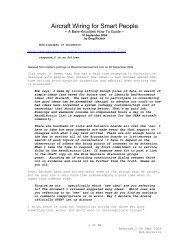
<strong>MIL</strong>-W-<strong>22759E</strong>4.6.2.2.1.2 Extruded fluoropolymer primary insulation or jacket. Unlessotherwise specified, specimens of extruded fluoroplymer primary insulation orjacket shall be carefully removed from the ccwkktor and tested for tensilestrength ard elongation in accordanm with EEIH3TD-228, Mthods 3021 and 30<strong>31</strong>respectively,except that the rate of travel of the per-actuated grip of thetensile machine shall be 10 +2 inches per minute for tests of plyvinylidenefluoride specimens. Not applicable to crosslinked constructions.4.6.2.2.2 Dielectric strength of unsure rted tapes. Samples of tape shallbe subjected to the short-time test of ASTM Standard D149. Stainless steelelectrodes 1/4 inch in diameter and having edges retied to a l/32-inch radiusshall be used. The radius must be accurate, and should be checked on anoptical mmparatir. Voltage shall bs increased at approximately 500 volts persecond. Tapes shall be tested with oil as the mediun. Tk oil shall be uspecified in <strong>MIL</strong>-L-23699.4.6.2.2.3 Specific gravity of Unsw rted tapes. Samples of tapes shallbe subjected to Test WthdAof AST?4Standard D792. A suitable wetting agentshall be added to the water to assist in axnplete wetting of the surfaces ofthe specimen.,..’4.6.2.2.2.4 ‘Il?Econtent of mated fibrous glass yarns and tapes. Aweighed specimen of the coated fibrous glass shall,be ignited for 4 lmurs in amuffle furnace at 700~. The residue shall be moled and weighed and *loss in weight calculated as H content of the coated tape or yarn..-4.6.2.3 Circumferential elmgation (extrudedTFE or abrasicm resis~tm insulationonly). This test method measures the elongation of a thin slugof wire insulation in the circumferential (radial)direction. The wireinsulationslug is radially elongated by axial nnvenmt of a tapered conethrough the stationary slug. The overall test apparatus is shown in Figure 1.A 1 to l-1/2-inch slug of insulatim shall & removed fran the mnduotor. Weshall be taken to prevent scratching, crimping, stretching, or otherwisedamaging the insulation. The diameter of the exposed mnductor should bemeasured to the nearest 0.001 inch. Cut five test ispecimns 0.125 inch ~.02inch in length fran the insulation slug using a sharp razor blade or anappropriate sanple preparaticm fixture. Both ends of the test Specim?ns shallbe cut square. Slide a specimen onb the cme until it just ~hs the edgesof the cone. The maw should be attached @ a moveable crosshead as sbwn ~Figure 2. Position the specimen holding block perpendicular to the cone asshown in Figure 3. Align the mne tip and the appr~riate sized holeof thespecimen holding block for the wire size being tested. ~ve the - timghthe sEaticnary specimen at a uniform speed of 20~.2 inches/minute until thespecimen ruptures. Determine the length of the mne that has passed throughthe specimen causing rupture. The peroent cimumferential elongation (% CE)is calculated as follows:“-..—,23Licensed by Information Handling Services
<strong>MIL</strong>-W-<strong>22759E</strong>%CE= (2x Lx Tang-Cm) Xloo%CDL= Cone length required b rupture specimn (inches)CD= ~nductor dianwter (inches)e =Measured croneangle taper (deqrees)2x Lx Tane= Inner diameter of the test specimen at rupture (inches)Five specimmscalculated.shall be tested and the average value of the five specimens4.6.2.4 Spark test of primary insulation (wkn specified~ 3.5.3). Thewire, after ap@ication of the primary insulation @ prior to the applicationof any other interial, shall be passed through a chain electrode spark testdevice using the voltage and frequency specified in the applicablespecificationsheet. The electrode shall be of a suitile bead chain or finemesh amstruction that will give intimte metallic mntact with practically allthe wire insulatib surface. Electrode length and speed of wire lmvement shallbe such that the insulation is subjected b the test voltage for a minimm of0.2 seared. Any pxtion showing insulation breakdown shall be cut out of thswire including at least 2 inches of wire on each side of the failure.* 4.6.2.5 Conductor or insulatia 5Plices. Unless otherwise specified inthe procurement contract, certification of conformity to tk splicing requirementsof 3.5.1.2 and 3.5.2.1 shall be axeptable. R&wer, * Goverrnnentreserves the right to inspect any splices in ttn s~les of 4.5.1.1.1 @4.5.1.1.2 and to observe any splicing performed during insulatia of the wire(see 4.5.1.1.3).4.6.3 Test methods for finished wire. Fkthods of test of tk fi.niskdwire shall be as follows.4.6.3.1 <strong>Im</strong>ul se dielectric test.4.6.3.1.1 Test equ”pnent. The electrode he~ through which the wire isgassed in the impulse dielectric test shall & of a suitable bead chainconstructicm such that tk electrode will give intina~ ~tallic intact withpractically all of the wire insulation surface. The CharaOtertiti~ of ~.- test inpulse and of the equi~ntfollows:auxili~ to the electrode he~ shall be as.-.-.-.(a) Test imul se. The wave form of the voltage supplied to-. the electrode head shall consist of a negative pulse, thepeak magnitude of which shall be as specified in theap@icable specification sheet, followedby a daqedoscillation. The rise time of the negative impulse wavefront fran zero magnitude to 90 peroent of the specifiedpeak voltage shall be not more than 75 microsemnds. Thepeak value of the first positive overstnot and each of thesubsequent dampd oscillaticms shall be smaller than the24Licensed by Information Handling Services
<strong>MIL</strong>+-<strong>22759E</strong>FG.1 clRcuM~ELoNcAnoNAPfwwuS!!4- NOMWL(X)NEANGLETAPERI --1-1 (8° NOMINAL TOTU W3ws.UMIN.11 .- - .50ukMN~...— e ———Y -1w mm , ---- .—4 RMSNQMIW.I1- —.— ——— ——— -JnC.2T=T~ FORaRcuWmmML ~~..1I.-..HOLESUES430 y12-1610-28 1/32.-25Licensed by Information Handling Services
<strong>MIL</strong>-W-<strong>22759E</strong>initial negative pulse. The time during which each ~lseaml accompanying damped oscillation (positiveand negative)remains at an absolute ptential of 80 percent orgreater of the specified peak voltge shall te 20 to 100microseconds. The @se repetiticm rate shall be 200 to250 pulses per second, inclusive. Except for the finalpeak voltage adjustment {4.6.3.1.3)conformity to thesetest impulse parameters shall & determined with no capaeitive load impressed upon the electrode.(b)(c)(d),..,Capacitive tileran~. The tolerance of the equipnent bchange in capacitive bad shall be such that the peak outputvoltage &all not be reduced by more than 12 @rcentin the event of an increase of capacitive load betweenelectrode and grourd, fran an initial load of 12.5 pifaradsper inch to 25 picofarads per inch of electrodelength.Instrument voltmeter. Cmnected to the electrode heti,there shall be a peak reading voltmeter indi~ting amtinuallythe pte~tial of tliielectrode. The voltmetershall slxw full deflection at a potential not exceeding 15kilovolts and shall have a minimum accuracy of 14 percentat the specified test impulse potential.Failure detectiw circuit. There shall be a failure detection circuit to give a visible or audible indicationof insulation fail&e, au~tically deenergize * eleetrode head, and stop progress of the wire through theelectrde. T& detectinq circuit shall be sufficientlysensitive to indiate a Zault at 75 percent of the sp&i-”fied test voltage when the electrode is arced to grcxxdthrough a 20 kilohn resistor ad shall be mpable ofdetecting a fault which lasts for the duraticm of only oneimpulse.4.6.3.1.2 Calibration of inpulse dielectric test ~“ Pt. ~ instw_.-.ment voltmeter shall be calibrated bv ~r ison with an ~xternal stardardvoltxnetercapable of detecting the @ak &tential at tk electrode bead with orwithout auxiliary circuitry. In performing the calibration, the standard voltmetershall be cxmnected to one of th electrode bads directly or through acalibratxxlattenuator circuit. The impulse generator shall be energized andthe voltage amtrol of the inpulse generator shall be adjusted until thereading on the standard voltmeter is the specified potential, at which point.- the reading on the instrument voltmeter shall be observed and remrded. Thiscalibration shall be repeated for each peak potential at which it is intendedto operate the equipent. An altermtive pr~dure is by means of a calibratedoscilloscope connected to the electrde through a suitable attenuator. The‘@ak magnittie of the negative pulse can then be read directly fran the waveform display. M oscilloscope connected ti the electrcilehead at suitable testp6i6ts shall also be used to verify conformance to the other waveformparameters specified in 4.6.3.l.la.26Licensed by Information Handling Services
?41L-W-<strong>22759E</strong>4.6.3.1.3 Inpulse dielectric test procedure. The finished wire shall kthreaded throuqh the electrode head ati the cxmductor shall & qrounded at oneor lmth ends. ‘The electrode shall be energized to the specifie~ peak ~tentialard after final adjustment of the voltage with wire in the electrode head, thewire shall be passed fran the pay-off PI through the electrde and onto thetake-up spool. The speed of passage of the wire through the electrode shall.bes~h that the wire is subjected to not less than 3, nor nmre than 100 pulses atany given point. linydielectric failures which occur shall be cut out ormarked for later removal along with at least 2 inches of wire on each side ofthe failure. During all parts of the test, including string-up of new lengths,every effort shall be nmde to test the entire length, incltiing ends of thewire, in accordance with this procedure. All ends or other portions of thewire not so tested shall be removed subsequent to the test. When specified hcontract or order (6.2), dielectric failures, untesbsd prtions of wire, orportions which have been exposed to fewr or ~re than the specified nunber ofpulses my be marked by stripping the insulation or by other suitable =thd ofmarking as specified in the mntract in lieu of teing cut out of the wire.4.6.3.2 Insulation resistance. The uninsulated ends of a wire specimen atleast 26 feet in length shall be connected b a positive IX terminal.ard &specimen shall & immersed to within 6 inches of its ends in a water bath, at25 ~5°C (77 ~9y), ~taining 0.5 t.o1.0 percent of an anionic wettingagent. The specimen shall remain inmersed for not less than 4 hours, afterwhich a ~tential of not less than 250 volts, nor more than 500 volts shall bapplied between the conductor and t~ water bath which serves as the secmdelectrode. The insulation resis~ shall te determined after one minute ofelectrification at this potential, ard shall b expressed as mgo*1000 feetby the following calculation:Megokmw1000 feet = ‘oW - cimen resistarm (- tma) x insnersd lemath (faet~10004.6.3.3 Wrap test.4.6.3.3.1 For extrkled insulation (“wrap back test”). For wire sizes 4?d ~~er. a 12-inCh SUt?ChWi KhS Zddithd k@Lh fbr %hd- of ffiwireshall & bnt back &n itsel? at the mid-porti~, on a radius-not lessthan the radius of the wire, and one end of the specinen shall be wound tightlyaround the other end as a mandrel for four~close turns. For sizes 2 andlarger, the specinen shall be wound for four close turns aroud a mandrel ofthe diameter specified in the specifi=tion sheet. In either ~se~ ~ ~of t@ specimen shall be left unsecured to permit unhampered relaxation ofthe turns. TM specimm shall then be placed in an air oven fir 2 hours at thetemperature specified in the specification sheet. At the em Of tiis PeritiPthe specimen shall b visually examined, without aid of magnifi~tion forcracks.27Licensed by Information Handling Services
<strong>MIL</strong>-W-<strong>22759E</strong>4.6.3.3.2 For tape or braid insulation (mandrel test). A specinm offinished wire, with a length of 12 inches plus the additional length requiredfor winding on the mandrel, shall k woun& tightly for two cIose turns around amandrel of the diameter specified in the applicable specification sheet. Thewinding shall be in tte middle gnrtion of t-hespeci& so that 6 inches of eachend shall remain straight. The specimen shall then be remved fran themandrel, examined for cracks visually without aid of magnification, adsubjected to the dielectric test of 4.6.3.14.3.4.6.3.4 Durability of color markings. The durability of product idenkificationor mlor markings applied m the wire for coding shall.be evaluated at20 to 25% (68 to 77%) as follows:* 4.6.3.4.1 Durability testing ama ratus. The markings durability testershall be designed to hold a short Specbn of finished wire firmly clmped ina horizontal positim with the -r longitii.nal surface of the ~inlSn fullyexposed. The instr!,mentshall he capable of rubbing a mall cylindrical.mandrel, which shall be a sewing needle 0.025 ~.002 inch in d~ter, repeatedlyover the upper surface of the wire in such position that the longitudinalaxes of the mandrel and the specimen are at right angles to each otherwith cylindrical surfaces in cmtact. A weight affixed to a jig abve themandrel shall control the thrust normal to the surface of the insulation. Amotor driven recipr~ting cam mechanisn arxlcnunter shall be designed todeliver an accurate n-r of abrading strokes in a directicxaparallel to theaxis of the specimen. The length of the stroke shall be 3/8 inch and thefrequency of & stroke shall be 120 strokes (60 stroking qcles) per YIhIte.* 4.6.3.4.2 Durability testinq Prooedure. In performing the test, a specimenof finished wire shall b nmnted in the specimen claup and tb jig shallte adjusted to deliver a weight of 500 grams through t& abrading mandrel tothe markings on the insulation. The specimen shall be subjecti ti 125abrasion cycles (250 strokes) of * mandrel and shall tkn ~ examined. Ifthere is a continuxs line of erasure or obliteration through the stripe, Xor printed identificationmarking, e-sing the primiry insulation, thespecimen shall be considered as having failed. Three specimens Shalx be testedfran each sample ~it h failure of any speciuen shall mnstitute failure Ofthe sample unit..-4.6.3.5 Bbcking. 03s end of a pie& ‘of finished wire, of sufficientlength to perform t~ test, shall be affi~ to a metal spol of the barreldiameter specified for the applicable wire size in Table IX. The Wire SWthen ‘bewound helically on the S- for at least three turns, with thesucceeding turns in close mntact with one another. The tension for windi~shall be equal to the test load specified for the cold txd test of the S-.- size wire in the applicable specification sheet. !rhewinding shall beamtinued until there are at least three closely-wound layers of such helicalturns on the spool. The free end of the wire shall then be affixed to the. . s-1 so as to Drevent unwindinq or loosenin9 of t~ turns or layers ~ tie“@ol and wire &hall te pla~d ~or 24 lxxrs in an air oven at tk temperature28Licensed by Information Handling Services
<strong>MIL</strong>-W-<strong>22759E</strong>specified on the applicable specification sheet. At the end of the 24-kxxrperid, the spool and wire shall be renmved fran the oven and allowed to coolto rom temperature. After cooling, the wire shall & unwound nmually, meanwhilebeing examined for evidence of adhesion (blocking)of adjacent turns orlayers. (A metal mandrel of diameter equal to the specified spol barreldiameter may be used in lieu of a PI for this test.)4.6.3.6 Wire weight. The weight of each lot of finished wire shall bedetermind by Procedure I (4.6.3.5.1). Lots failing to met the wire weightrequirement of the applicable specimn sheet when tested in acmrdance withProcedure I shall be subjected to F’rocedureII (4.6.3.5.2). All reels orspools failing to meet the reguirenents of the applicable specifi-tion sheetshall be rejected. The sampling plans of 4.5.2.1 are not applicable inProcedure II.4.6.3.6.1 Procedure I. The length and weightof a specimm at least 10feet long shall be a~urately wasured and the resultant measurements convertedto prods per 1000 feet.4.6.3.6.2” Procedure II. The net weightof the finisbd wire on each reel “or spool shall be obtained by subtracting the tare weight of the reel or -lfrom the gross weight of the reel or -l and the wire thereon. The netweight of the wire on each reel or spool shall be divided by the exactlydetermined length of wire on that reel or spol and the resultant figureconverted to pounds per 1000 feet. When wod or other moisture a-rbentmterials are used for reel or spool instruction, gross and tare weightdeterminations shall be made under su~tantiallv.the same conditions ofrelative hunidity.4.6.3.7 Conduclmr resistance. The Wmeasured in accordance with l@tlKxI6021 ofshall be tested dry without ixmmxsion.4.6.3.8 Conductir elongation and tensile strength.resistance of the conductor shall bel?IZHm228 except that the wire* 4.6.3.8.1 Soft or annealed copper. Elongatia tests of =ft or annealdcopper conductors shall he performed in accordancewithkfdbd 32UofFED-ST&228, except that the elongation at break of tk individual strand or of‘- the first strand of the whole conductor, “asapplicable, shall be detenrd=d bymeans of a recording chart on the testing machine ra~r than by neasuri.ng&specimen after the break. For wire sizes 20 and larger, the tests shall beperformed upon individual strands hken fran the mnductor of the finishedwire. For sizes 22 and smaller, the tests shall be perforned upon the wholeconductor rermved frcxnthe finished wire and the elongation shall be measuredwhen the first strand of the conductor breaks. For wire sizes 20 and larger,only the values obtained with individual strands shall be umsidered and, forwire sizes 22 ad smaller, only the values obtained with the whole cxmductorshall be amsidered in determining the conforman~ of soft or annealed wpper-mnductors to elongation requirements of this specifi=tion.<strong>29</strong>Licensed by Information Handling Services
KIL-W-<strong>22759E</strong>* 4.6.3.8.2 High strength wp per alloy. Elongation and tensile stre~thtests of high strength alloy conductors shall be Performd in acczxdance withMettd 3211 of EED-STD-228 except that the tensile strength shall b reportedas the tensile breaking strength of the conductor rather than in prods persquare inch; also, the elongation at break of the first strand of the wholeconductor shall be determined by means of a recording chart on the testingmachine rather than by measuring the mnductor s~cimm after the first strandbreaks. The tests shall be performd upn the whole cxxductor removed frun thefinished wire. Conductor elongation shall be measured when the first strand ofthe conductor breaks, ard the total tensile force indicated by the testingmachine at break of that strand shall & regarded as the breaking strength ofthe conductor. Only the values thus obtained with the whole conductor shall beconsidered in determining the conformity of high strength all~ mnductors tothe elongation and tensile strength requirmnts of this specification.4.6.3.9 Cmcxmtricity. The mncentrici~ of the primary insulation and ofthe finished wire shall be determined in acmrd~ with the procedures of4.6.3.8.1 and 4.6.3.8.2 as appli~ble. All wall thickness measurements SWbe made on cross sections of the wire under suitable uegnification. A wallthickness shall be the shortest distance between the outer rim of the primaryinsulation or finished wire, as ap@icable, ard the outer rim of the outerxrOStstrard of the oonductor.4.6.3.9.1 Concentrielay wires. The cmcentrici~ of the primry insulationor of the finished wire shall be determined by first locating and recordingthe minimum wall thickness nraasuredon a cross secticm of the primryinsulationor finished wire. The maxhmm wall thickness of this sam crosssection of the primary insulatim or finished wire shall also be l-ted andremrded. For concentric-lay wires, 100 times the ratio of the mini.mumwdlthickness to the mximm wall thickness shall define the percent concentrici~.4.6.3.9.2 ~lav wires. The concentricity of the primary insulatim orof the finished wire shall be determined by first locating ati recording theminimum will thickness measured on a cross Sectia of the primary insulaticm orof the finished wire. From this point on the outer rim of the primaryinsulationor finished wire .atwhich the mininum wall thickness was neasured~three nrxe reference points 90 degrees apart on the outide rimof W pr~insulationor finished wire shall be establiskd. At each of - thre‘- reference points the nearest mmber of the rope-lay cmductir shall be selectedand the minimum wall thickness between that member and the outer rimof theprimary insulation or finished wire shell be measur@. The average of the ~rreadings shall be cxmsidered to be the average wall thickness, For rope-laywires; 100 times the ratio of the minimwn wall thickness to the average wall- thickness shall define the percent concentricity..-.-,.---, .-30Licensed by Information Handling Services
<strong>MIL</strong>-W-<strong>22759E</strong>* 4.6.3.10 Shrinkage. tie inch of insulation shall te stri~ fran eachend of a 14-inch specimen of finished wire, using a razor blade or equivalentheld perpendicular to the axis of the wire for the insulation-remval operation.The length of exposed conductor at each erd of the specimen shall bedetermined to the nearest 0.01 inch. The specinen shall be exposed to theterprature specified in the applicable Specification sheet for 6 hours in anair oven. At the end of this period, the speci~ shall be renmved fran theoven and allowd to return to rocrotemperature. The shrinkage of the insulationshall then be measured as the greatest additional distance which any layerof the insulation, including jacket if present, has receded from either erd ofthe conductor; that is, the measurement obtained at the end showing the greatershrinkage shall be considered the shrinkage of the spechn. ~ specimenshall be tested fran each sample unit..-..-4.6.3.3.1. Nicking. Wicki.ngshall.be determined by Procedure I or II asspecified in the applicable specification sheet.4.6.3.11.1 Procedure I. The wire specimen shall be 4~1/16 inches inlength, with square-cut ends, ati shall be weighed accurately b the nearest0.1 milligram. The weighed specimen shall be placed upright with the lower 2inches of its length immersed in distilled water in an open mntainer ati shall& conditioned thus for 24 hours at r- temperature in a draft-free area. Itshall then be remved fran the distilled water, the surfa~ of the insulationshall be wiped free of excess misture with a clean, dry, lint free cloth, d,within 5 minutes af&r r~val fr~ the water, the specimen shall.be weighedagain to the nearest 0.1 milligram. Change in weight shall te calculated topercent of the original specimen weight.4.6.3.3.1.2 Pr~dure II. The specimn and the procedure shall be identicalwith Prtiure I except that standard dye solution (4.6.3.11.3)shallbesubstituted for the distilled waber of Procedure 1. In additia, inm?diatelyafter the final.weighing, the specimen shall be observed tier ultravioletlight to de&~ine, to t~ nearest 0.05 ind, the dismm th dye soluti~ hsstraveled in any part of the insulation by wicking action. The layers ofinsulatim nmy be dissected away with a sharp We, winking frcm th -rad of the specimm, to facilitate observation.4.6.3.11.3 Standard dye solution. Th& ‘dye solution shall be prepared asfollm:-. Ethyl almhol 30 mlRkx3amineB dye0.02gmAerosol (YJ!(.75% soluticn) 3mlDistilled water to make2 litersThe dye shall be dissolved in the ethyl alodml before adding to the water.The solution shall be kept stoppered ad a fresh solution shall be prepared“every 30 days, A new portion of the solution shall b used for each testXMM3ucted,,.. ,Licensed by Information Handling Services<strong>31</strong>
KIL+-<strong>22759E</strong>* 4.6.3.12 Low temperature (cold tend). me end of a wire specinm 36inches in lenqth shall be secured to a ro& table mtirel in a cold chamber andthe other end-to the load weight specified in the applicable ~cif icationsheet. The diameter of the mandrel shall be as specified in the specificationsheet. Provision shall be made for rotating the mandrel by means of a handleor a)ntrol located outside the chamber. The specimen of wire and the mardrelshall be conditioned for 4 hours at tbe temperature specified in the appli~especifi~tion sheet. At the erd of this period and while both madrel ardspecinen are still at this low temperature, the specimen shall be wrappedhelically for its entire length or for 20 turns, whichever is the lesser numberof turns around the nmndrel without cpening the chamber. The bending shall beaccomplished at a uniform rate of 2 ~1 RPM. At the cxxnpletionof this testthe specimen shall be remved fran the cold tox and fran the mandrel witbutstraightening. The specimen shall be examined without magnifi~ticn for cracksin the insulation. The insulation shall then be renrwed for a dismce of 1inch fran each end of the speciti and the specimen shall & subjected to thedielectric test specified in 4.6.3.15.3with the bent portion suberged.4.6.3.13 Thermal shock resistice..,1!4.6.3.13.1 Preparation of specimen. A specimen of wire five feet lmgshall be prepared by carefully removing 1 inch of insulation fran each eti ofthe wire. (Forpurposes of this test, insulation is defined as all layers ofnon-cmdubting material covering the electrical conductor, e.g., primary insulaticnlall tapes and braids, and the jacket.) A ra?xx blade or equivalent?held perpetiicular to the axis of the wire, shall be used b cut the insulationfor the removal operation. The length of exposed mnd~r at each end of thespecti shall be measured to the nearest 0.01 inch. The specb @ *formed into a lcose mil not less than 1 foot in diameter and shall & laid ona wire screen for handling thrcuglmut the test.--4.6.3.13.2 Test pmcxhre. The Specimm shall & pleoed for 30 minutes ina preheated air circulating oven at the temperature specified in the applicablespecificatim sheet. The specimen shall then be remved fran the oven arm3within tm minutes, placed in a chamber which has been precooled to -55 ~* “(-67~3.@P) . It shall be exposed & this temperature for 30 mirmtea?after which it shall h remnved ard allowd a minhan of 30 minutes ~ return— to rcm temperature, 20 to 25% (68 to 77hJ. &t the mnclusicn of tiiscycle, the distance frun the erxlof each layer of insulation to the eti of theconductor shall be measured ~ the nearest 0.01 inch. This thermal shock cycleam5 the measurements shall be repeated for an additional three ~les (a to@lof four cycles). Any measurement varying fran th original measurement by morethan the amunt specifi~ in the applicable specification sheet shallconstitute failure. Any flaring of any layer shall also constitute failure.*.. ,32Licensed by Information Handling Services
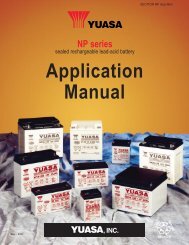
<strong>MIL</strong>-W-<strong>22759E</strong>4.6.3.14 Flammability.4.6.3.14.1 Apparatus. The flanunabilitytest chamber shall h approximatelyone foot square by two feet in height, ati shall be open at top and front toprovide adequate ventilation for ccmhustion but prevent drafts. Means shall beprovided in the chamber to hold the test specimen taut at an angle of 60degrees fran horizontal in a vertical plane prallel to and akout 6 inches infront of the rear wall of the chamber. The test burner shall be a Bunsen typegas brner having a l/4 inch inlet, a needle valve in the base for gasadjustment, a bore of 3/8 inch ncminalt and a length of approximately 4 inchesatwve the air inlets. The burner shall be fitted with a wing top flamespreader having a l/16 inch by 2 inch opening.4.6.3.14.2 Pr~dure. ‘A 24-inch specinm of wire, marked at a distan=of 8 inches frrxnthe lower eti to indicate the point of contact for the testflame, shall be clamped tautly, at 60 degrees fran horizontal, in the speci~holder of the test chamber. The burner shall be adjusted b deliver an allblueflame, 2 inches high, at a temperatureof 955~30% (1751~54%),as measured with a therrrucouplepyrrxneter. With the burner held at a 90 degreeangle to the wire specimm and the long dimension of the flaresspreader ~parallel to the axis of the specimen, the hot tip of the flame shall be appliedto the wire so that,the midpint of the flane touches the 8-i.ncbmarkon k&specimen. The period of flaresapplication shall be 15 semtis for wire sizes30 through 18, 30 secnnds for sizes 16 through 12, lminute for sizes 10through 4, ard 2 minutes for larger sizes. At the close of the applicationperiod, the flame shall be withdrawn and”the duratimof & after flame in theSpecimenshau be noted. When required by the applicable specification sheet~the burned section of the wire specimen shall ke subjected to the ~st-fldielectrictest of 4.6.3.14.3 are met. Breaking of the wire spec~ns in sizes24 and smaller shall mt be amsidered as failure provided tlE requirenmt forflame travel limits, when specified in the applicable Specificxitionsheet, adduration of fl~ requirement axe uet.,,...s. .4.6.3.14.3 Post-flame dielectric test. When apst-flame dielectric testis required, the specimen fran the flame test shall be cl- firnilyin akrizontal positia, leaving the burned prtionof & wire accessible ti acontact plate jig equal to that shown in Figure 4. The bttcmmntact pl.abshall be D-d uderneath tk! wire and shall make wntact with the -Iiter‘--1/2-inch-&ea of the burned section of thewireon the side of the insulationwhich has been nearest the flame. ‘lhe upper mntact plate shall be placed ontop of the specimen, directly over the bottan plate, atia v4-pm3 weightshall-b placed on the upper plate, directly over the specimn, to insurecontact with the burned area. The voltage specified in the applicablespecifitition sheet shall then be applied between the conductor of the specinmad the amtact plates of the jig. The voltage shall be gradually increased ata uniform rate fran zero to the specified voltage in l/2 minute, maintained atthat voltage for 1 minute W gradually redu~ to zero in l/2 minute. There. shall be no dielectric failure of the specinen under this test.. . . .33Licensed by Information Handling Services
IKIL-W-<strong>22759E</strong>4.6.3.15 Life ICYcle.4.6.3.15.1 Air oven. me inch of the insulation shall be remved franeach end of a 24-inch specimen of finished wire. The central pxtion of thespecimen shall then be &nt over a hximntaUy placed mindrel of the diameterspecified in the applicable specification sheet. Each eml of the amductorshall & loaded with the weight specified in the specification sheet, so thatthe portion of the insulation between the conductor and mndrel is undercompression and the conductor is under tension. This specinrm, so prepared onthe mandrel shall be placed in an air-circulating oven and maintained for apericd of 120 hours or the length of tine specified in the specificationsheets, at the tenpxature specified in the s~cifi~tion sheet. Afterccmpleticm of the air oven test, the specimen shall te cooled to between 20 and250C (68 b 77W), within a period of 1 hour. When molad, the wire shallbe freed from tension, remved fran the mardrel, ard straightened. The~=imn shall be examined for color retention (3.6.4). Tb specimen shallthen be subjected to the tend test (4.6.3.14.2) fol~ by dielectric test(4.6.3.14.3). After the dielectric test, the insulation rhall & renmed franthe s-* ‘and the conductor shall & examined for piu”~q . ,. ... ...----+:.’,4.6.3.15:2 Bend test. In a temperature maintained between 20 and 25*(68 to 7fi) , one end of the specimn shall be secured to the mandrel andthe other eti b the load weight specified in the applicable specificationsheet. The mandrel shall lx rotated until the full length of the specixmm iswrapped arourx3the mandrel and is tier the specified tension with adjoiningcoils in contact. The mandrel shall then be rotated in reverse direction mtilthe full length of the wire which was outside during the first wrapping is mwnext to the mandrel. This procedure shall be repeated until two M in eachdirection have been formed in the ram section of the wire. Th outer surf=of the wire shall then be observed for cracking of the insulation.4.6.3 .15.3 Dielectric test. The uninsulated ends of the specimm shall *attached ~ an electric lead. The specinen shall be inmersed in a 5 percent,by weight, solution of sodium chloride in water at 20 to 25% (68 m 7-),except that th uninsulated eti and l-1/2 inches of insulated wire at each endof the specimen shall protrtie atwe the surface of the solution. Afterirfrnersionfor 5 bmrs, * voltage specified in th applicable specificationsheet at 60 hertz (cycles per seared) shall be applied between the ~r“- and an electrode in amtact with the liquid. This voltage shall & 9r~uallYincre- at a uniform rate frcm zero to the speoified voltage in 2./2minutelmaintained at that voltage for a period of 5 minutes, ad gradually redu- tozero -~ 3/2 minute.4.6.3.16 <strong>Im</strong>mersion tests. Specimens of wire of sufficient length toperform the subsequent tests shall te gaged to determine their initial diameter.-and.shall then be inmersed to within 6 inches of their ends in each of thefollowing fluids (using a separate specimen for each fhid) for 20 <strong>Im</strong>rs at atemperature of 48 to 500C (118.4 to 1220F for fluids (a) and (b) and at.-20 ~20c (68 ~3.60F) for fluids (c) and (d)..-. - (a) Lubricating oil, aircraft, turbine emgine, synkhethicbase, <strong>MIL</strong>-L-23699.34Licensed by Information Handling Services
141L-W-<strong>22759E</strong>+-a’”POSITION OFWIRE SPECIMENSET SCREW3 1/2-q++fv‘H1/8-lt- 9/320“i1:.IaLIMNERIALBASE NONCONDU~RCONTACT PLATES: POLISHEDUPRIGHT SUPPORTS BRASSIBRW.5P.2 1/21“14.,! .L. .... . .. -+*3/4\PosmoNoF wlREsPEaMEN(NolE6uRt4msEcnoN)--. .. ..-. ,,.-FIWIW 4. CCt?I?AC1’ PLXI’EJIG FOR P06WELAME D~C TEST.35Licensed by Information Handling Services
<strong>MIL</strong>-W-<strong>22759E</strong>(b)(c)(d)Hydraulic fluid, petroleum base, aircraft missile, andordnance, <strong>MIL</strong>-H-5606.Isopropyl alcohol, TI’-I-735.Turbine fuel, aviation, Grade JP-4, <strong>MIL</strong>+’-5624.During the imrsion tests, the radius of bend of the wire shall be not lessthan fourteen times the spscified naximum diameter of the wire urxlertest.Upon remval from the liquids, the specimm shall remain for 1 bur in free airat roan temperature. The diamter shall be gaged ard ca’rparedto the initialdiameter. The insulation, braid, and protective mating shall be remved for adistance of 112 inch from each erd of a 24-inch length of the specimen and thislength shall be subjected to the bend testof 4.6.3.14.2 follmed by thedielectric test of 4.6.3.14.3.4.6.3.17 Hmidity resistance. A S2-foot specimen of wire shall besubjected to the following:4.6.3.17.1 Apparatus. The apparatus shall oonsist of a test chmtercapable of maintaining an internal temperature of 70~20C (158~3.60F’)and an internal relative humidity of 95 +5 percent. The test chamber SWbe capable of being so sealed as b retayn the total misture content in thetest space. The heat loss fran the chamber shall be sufficient to reduce theinternal temperature frun the atrwe ~cified operating temperature ~ not nmethan 38% (100.4~) within a period of 16 hours fran the time of remvalofthe source of heat. Distilled or demineralised water shall be used ti obtainthe required hmidi~.4.6.3.17.2 Prooedure. The specinm shall be placed in the test chamber andthe temperature and relative hunidity raised over a 2-hour period tn the valueSspecified in 4.6.3.16.1 and maintained at such for a period of 6 hxrS. At theend of the 6-hour pericd the heat shall be shut off. During the follow@16-hour periti, the temperature nust drop to 38% (100.4%) or bwer. Atthe end of the 16-hour periodr heat shall be again supplied for a 2-bur periodto ~~bili~ at 70 +2% (158 +3.6%). This cycle (2 hours heating, 6hours at high ~~ature, 16–tis cooling) shall h repsated a auf ficientnumber of times b extend the total time of the test to 360 hours (fifteen- ‘cycles). At the end of the fifteenth cycle,-the 50-foot oenter section of the@ecimen shall be inmrsed in a 5 prosfit, by weight, solution of sodimchloride in water at mm temperature. The insulation resistance of thespedmn shall be neasured with the outer surface of the speck grti~~through an electrode in the electrolyte, ad with a po&ntial of 250 b 500volts XX applied to the oxductor of the specimen after 1 minute of.- ehctrif ication at this potential. The insulation resis~ shall beconverted to ~ohms for 1000 feet by the calculatim shown in 4.6.3.2.---..-.36Licensed by Information Handling Services
<strong>MIL</strong>-W-<strong>22759E</strong>4.6.3.18 Surface resistan-. The surface resistance of the finishedwire shall be measured in acmrdance with Method 6041 of FED-STD-228. Allspecimens, after having ken provided with the required electrodes but prior totesting, shall & cleaned by the procedure described in the test method. Inpositioning the spcimns in the test chamber, the specirens shall ke so placedthat their ends are a minimcm of one inch fr~ any wall of the chamber.4.6.3.19 Smke. This test shall & mnducted in still air at an ambienttemperature of 25 +5°C (77-&9y). h specimen approximately 15 feetlong of the wire s~all k so suspended that at least the central 10-botsection is horizontal and unsup~rted. Che end of the wire shall be suitablyweighted in order that no sagging will occur throughout the test. An electriccurrent shall be applied to the wire, and the voltage drop ueasured over thecentral 10-foot portion. Fran the current arxlvoltage values, the resistanceof the wire shall be =lculated. The temperature of the wire ccnductor shallbe determined frcn the change in resistance. ‘l? recurrentshall be soadjus=that the conductor temperature stabilizes at the temperature specified in theapplicable specification sheet. This conductor temperature shall be thusmaintained for 15 minutes during which time there shall be no indicationofvisible smke. A flat-black backgroud shall be used for this test.4.6.3.20 Acid resistance. When acid resistan~ is specified in thespecification sheet, specimens of finished wire, 24 inches long, shall have l/2inch of insulation rennved at each end. The specinm=nsshall then be inmersedto within 1-1/2 imhes of each end in red flxningnitric acid (specificgravity,1.52) at normal room temperature for 8 hours. Following this bmnersion inacid, the specimens shall be renrwed and inmersed, except for l-1/2 inches ateach end, for 1 hour in water at rcrm temperature mntaining O.S percent ofaerosol or equivalent wetting agent. The specimens in the wate~ solution shallthen be subjected b the’dielectric test of 4.6.3.14.3.* 4.6.3.21 Continuous lengths. Unless otherwise specified in the orderingdata (6.2), the inspection requirements for cmkinuous wire lengths shall besatisfied by the su@ieris ~rtificate of conformity and the presen= of tMrequired pie@’length markings on the spools or reels (3.6.7). -ver~ ~Government resertis the right ti examine such certified lots if deemednecessary to assure that the lengths actually conform to requirement. When the--. ȯrdering data &pacifies examinatim of tkwire lengths, the Gmmnnentrepresentative shall examine the wire at his own discretion tideterndneconformity in this characteristic. In masuring continuous wire lengths wherethe wire has been marked or stripped of insulatim in lieu of being cut to markinsulation failures or identify untested or iqropsrly tested areas(4.6.3.1.3),suqh marking or stripping shall be considered equivalent to- complete severance,.of the wire at the tm ends of each nuked or stripped area.---...* 4.6.3.22 Solderability. Unless otherwise specified, five specinms, AiWl10and smaller, shall be prepared ard tested for solderability using MXhod 208 of.- &!IL-STD-202. The specimns shall be tested without steam aging using a type Rflux.-.Licensed by Information Handling Services37
<strong>MIL</strong>-W-<strong>22759E</strong>.* 4.6.3.23 Conductor strand adhesion (when required by the-specification* 4.6.3.23.1 Procedure for 19-strand ~ductor (wire sizes 26 throuqh 12).The specinm shall be a 6-inch length of the finished wire. With an insulationstrippingtool, a stripping actior-shall be initiated two inches from one endof the specimen. Without kinking or otherwise damaging the conductor, theinsulation slug shall be roved lengthwise ~til approximately 3/4 inch of theconductor is expsed. The specimen shall be renmmd fran the stripping tooland examined in a~rda~ witi 4.6.3.23.1.1 fbr unidirectional lay mxxluctoror 4.6.3.23.1.2 for true mncentric lay mnducbr (m 3.5.1.1.1), asapplicable.* 4.6.3.23.1.1 Unidirectional lay. Grip the insulation with the fingers atboth erds of the exposed porticn of the cxmductir ati rotate one ed of thes~cimen so as ti untwkt the exposed strands and make them parallel with theconductmr axis. (The use of rubber pads or similar holding aids is perudtted.)Retaining & grip poaitirm used to untwist the strands, ~sh the _ erdstoward each other in the conductor axis, causing the stratis tm spread apart ina ‘bird ~ge” effect. Gently probe unseparated strands with a fine needle orthin blade to determine whether they are adhered together by a metallic lxmW.ngor sinply lying side-by-side. Metallic lmnded pairs or groups of strands whichcannot be separated along the whole “bird cage” length without fircing tbneedle or blade between the strands shall each be cxx!ntedas me. The tntalnmber of unbmded single strands plus the nmber of wtallic brded pairs @netallic trendedgroups of strarxisin the specimen shall be mt less than 13(see 3.6.J.1). ,~e specimen shall be examined from each sauple unit..-* 4.6.3.23.1.2 Trw camxmtr ic lay. Grip the specim?n as described in4.6.3.23.1.1, but rotate the exposed prtion only enough to untwist the12-strarx3outer layer of the conductor. Push the ends of the expsed prtiontogether to “bird cage” this outer layer and determine with needle or blade, asin 4.6.3.23.1.1, tk nunber of unbended single strands, netdlic bnded pairsof strands, and metallic boxded groups of strards. Using a suitable tool, snipthrough each unbmded single strand and each bonded pair or group of strands ofthe outer layer approximately in the center of tk! ‘bird cage= and fold thesnipped ends back bnmrd the respective ends of the specimm. (Donot cut the7-strand oore of the mnducbr. ) tbw deferininethe count of unbended singlestrands, ~tallic bonded pairs, and metallic txmded gro~ in the 7-straIdcore, using tk procedure of 4.6.3.23.1.1. The total count fir * l~tr~outer-layer plus the 7-strand core shall be not less than 13 (see 3.6.11).me specimm shall be examined from each sauple unit.. .● ‘ 4.6.3.23.2 Procedure for conductors with other than 19 strands {wire sizes10 and larger). Pkdiqing the procedures of 4.6.3.23.1 through 4.6.3.23.1.2 asnecessary, the total count of unbended groups of strards in the omductir shallbe determined. ~ specimen shall be examined from each sample unit.. .-. ..-. .38Licensed by Information Handling Services
MXL-W-<strong>22759E</strong>4.7 Inspection of packaginq The packaging of materials ready for shipmentshall be examined to determ~e conformity to the requirenmts ofSection 5.5. PACKAGING5.1 Preservation and unit packaging. Preservation and unit packagingshall be Level A or Level C. Unless otherwise spcified in the cxntract ororder (6.2), Level A shall be applicable.5.1.1 Level A. Shall be in accordan~ with the Level A preservation, unitpack, requirements of FIXH-12000 ard as folh:* 5.1.1.1 Reels and spools. Wire shall be delivered wouru3on reels ardspools of a nonreturnable type. Each reel or -1 shall have an appropriatediameter for the respective wire size. In no case shall the barrel of the reelor spool have a diameter less than that specified in Table IX or less than 3inches, whichever is greater. Reels and spools shall be suitably finished bprevent corrcsion tier typical storage and handling conditions. The mettmd ofattachnmt of flanges b barrels on netal reels shall be structurallyequivalent to a full circumferential crimp.TABLE IX. BARREL D~ oF~ANDIUIELS.Wire Size,,,Minimum Diamter of Barrel (as TimesMinimum Dian@ter of Finished Wire,Except see 5.1.1.1)L30-14 50X12-10 40X8-1 30X0-0000 20%.-..-5.1.1.2 Winding requiremmts. Unless otherwise specified in the orderingdata (6.2), there shall h m restriction on tlm nmber of wire lenathe ~reel or &l, providd the wire length requirements of 3.6.7 ard ~ “W aremet by the inspection lot.5.1.2 Level C. Level C preservati&” &d unft packaging shall be inaccordance with the MIIA!-12000 Ievel C requiremmts Eor preservation unitpack.-.5.2 Packing Packing shall be Level A, B or C in acmrdance with<strong>MIL</strong>-C-12000. tl~ess otherwise specified in the order (6.2), ~vel C shall beapplicable.*..-. ...—. ,,39Licensed by Information Handling Services
<strong>MIL</strong>-W-<strong>22759E</strong>5.3 Marking. Unless otherwise specified in the contract or order, eachreel or spool shall be marked with the footage of the individual continuouslengths w&md thereon, as specified in 3.6.7; In addition, interior packagesand exterior shipping amtainers shall be marked in accordance with <strong>MIL</strong>
KIL-W-<strong>22759E</strong>a.b.c.d.e.f.Title, nunber ard date of this specification.Applicable specification sheet nunber, title and date.Applicable specification sheet part nunber (see 1.2.1).Color required (see 3.6.4).Quantity of wire required.Levels of packaging and packing required.9“optional provisions of this specifi-Exceptions, if any, tm tkcation including:{1)Respnsibili@4.1.for inspection, if other than ?ipecifiedin(2)(3)(4)Statement, if applicable, that =rtif iukia of conformi~(see 4.6.2.1, 4.6.2.3.4 and 4.6.3.20) will not be accepted.Statement should incltiletesting schedule b be substituted.Markingof dielectrictest failuresor irregularitiesbystripping of insulatia or by other method specified in tkcontract in lieu of cutting of the wire, if applicable(see 4.6.3.1.3).Special preparatim for delivery requir~ts, if applicxh.le(seeSection 5).6.3 Qualification. With respect to products requiring qualification,awards will be made only for such prducts as have, prior to tti ti= Set firopeningof bids, been t&ted and a&nxnmd for inclus%m in the applicableQualifiedProductsList (mL) whether or not such products have actually beenso listed by that date. The attention of the suppliers is =lled to this, rerjhiremnt, and ~ufacturers are urged to arrarge to have the products thattky propose to offer to the Federal Govermnent tested for qualificaticxlin----order that they may be eligible to be aw~ded contra@s or orders for theproducts covered by this specification. For all <strong>MIL</strong>-W-22759 specificationsheets identified on the lastpage of the docmnts as prepared& the Naval.Air SystemsCcmmnd (AS),* activityresponsiblefor QualifiedProductsListing (the“qualifyingactivity”)is the NavalAir SystemsChmad,Washington, K 20361-5110. (For the specification skets similarly- identifiedas preparedby Air Force-85, the activity resgxmsible for Qualified.- Products Listing is the Air For= Logistics Camnand, Electronic SupprtDiviSion, 2750 AB@2S, Gentile Air Force Station, Dayton, CEl 4S444-4500) .However, applimt ion for qualification of products for all specification sheetsshould be made to the Naval Avionics Center (Code 444), 6000 East 21st Street~“-Indianapolis, IN 46219-2189, who has been designated agent for establishingthe Qualified Products List..-. .41Licensed by Information Handling Services
<strong>MIL</strong>-w-<strong>22759E</strong>.-6.4 Conformity to gualified sample. It is understood that wire suppliedunder mntract should be identical in every respect to the qualificationsampletested and found satisfactory, except for changes previously appoved by the@vernment. my unapprovd changes fran the qualification sample shallconstitute cause for rejection.6.5 International standardization. Certain prwisions of this specificationare the subject of internaticmal standardization agreements (ASC AirStd. 12/5, and STANAG 3<strong>31</strong>7). When mmxhvmt, revision, or cancellationof thisspecification is proposed which will affect or violate the internationalagreements concerned, the preparing activi~ will take appropriate rewnciliationaction through international standardizationchannels includingdepartmentalstandardization,.offices,if required.6.6 Subject term (key word) listing.Aerospacewire electricalFinished wireConductor materialInsulating mterialStrandinga) Concentric lay strandingb) Rope lay stranding6.7 Marginalnotations. The marginsof this specifimtim aremarkedwithan asteriskto indicxitewhere significant changes fran the previous issue weremade. This was done as a omvenien~ only ad the Govermuent assunes noliability for any inaccuracies in these notations. Bidders ad omtractors arecautioned to evaluate the requirements of this dxunent based on the entiremntent as writtenirrespectiveof marginalnotationsand relationshipto thelast previousissue..,. ,custodians:Army-CR-! Navy-AsPreparirq activity:Navy-MAir Force-’85Agent:NASA-m mA -Is.-. ...Review activities:Army-AR, PE, MI ~ project 6145-U52)Nav..-BC, CEAir Force - 80MA-X5.,User--activities:Army - AT, AVNayy-m....Air Force - 11Review/user information is currentas of the date of thisdocunent. For futureooordinationof changesin this document~ draftcirculationshouldbe ba- onthe information in the current Federal Supply ClassificationListing of DODStandardization Documents.Licensed by Information Handling Services42
STANDARDIZATION DOCUMENT IMPROVEMENT PROPOSALINSTRUCTIONS1. The preparing activity must complete blocks 1, 2, 3, and 8. In block f, both the document number and revisionletter should be given.2. The submitter of this form must complete blocks 4,5,6, and 7.3. The preparing activity must provide a reply within 30 days from receipt of the form.NOTE: This form may not be used to request copies of documents, nor to request waivers, or clarification ofrequirements on current contracts. Comments submitted on this form do not constitute or imply authorization towaive any portion of the referenced document(s) or to amend contractual requirements.2. OOCUMENT DATE (WMMDO)1. -;:;;;& >i$i$!$KEM-wIMsi&:iwi.M$F;#.. ..... ... ......... . 90,12,<strong>31</strong>L DOCUMENT TJTLEWire, Electrical , Fluoropolymer-I nsul atedL NATURE OF CHANGE (Identify pragraph number ●nd include proposed rewrite, if possible. Attach ●xtra sheets ●s needed.)I5. REASON FOR RECOMMENDATIONI~._PREPARING ACTIVITY.—●. NAME b. TELEPHONE (W- Area Code)(1) Commercial (2) AUTOVON; Mmnanding Officer 201-323-7438 624-7438* .%oomssOJUl@czip code) WVW 00 NOTRECEIVE A REPLY WITHIN 4S OAVS, CONTA~:j ‘!4EC. SESD (Code 53) O@fmse Quality ●nd Stmdsrdiz40n Officet,akehurst, NJ 08733-5100,, . ... .—. _... - ‘ mm 14,26,OcT 89hwiws editions ●re obsolete.S301LWMrg Pike, Suite 1403. Falls Church, VA 22041 -3d66Tc@hone (703) 7S6-2340 AUTOVON 289-2340.WW5mLicensed by Information Handling Services
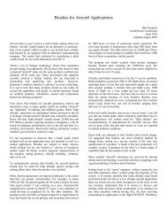
![G-Series-Ext [pdf] - Carling Technologies](https://img.yumpu.com/50918301/1/190x245/g-series-ext-pdf-carling-technologies.jpg?quality=85)