AUTO-PURGER for Plant Computer or PC - Hansen Technologies
AUTO-PURGER for Plant Computer or PC - Hansen Technologies
AUTO-PURGER for Plant Computer or PC - Hansen Technologies
- No tags were found...

Create successful ePaper yourself
Turn your PDF publications into a flip-book with our unique Google optimized e-Paper software.
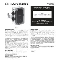
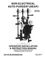
PURGE POINT CONNECTIONS“Foul gas” lines from condensers should be purged atpoints recommended by the condenser manufacturer.Usually, this is at the top of each circuit’s outlet headerwhich drains down through a P-trap to the receiver. Insome cases, a small high pressure auxiliary receiver islocated at the outlet of one <strong>or</strong> m<strong>or</strong>e condensers. Thisreceiver should have a purge point at the top, preferablyat a “dead” area away from condenser drain pipes.Below is a typical valve arrangement <strong>f<strong>or</strong></strong> a purge point(Figure 3). Regardless of the purge point location, itis absolutely necessary to ensure that liquid is notdrawn into the foul gas line.Figure 3ISOLATIONSHUT-OFFVALVE13 MM PORTREMOTE PURGE POINTSOLENOID VALVEremainder of the refrigerant is condensate from the “foulgas” line, which is collected in the drainer <strong>or</strong> condensedin the coil, and metered into the evap<strong>or</strong>at<strong>or</strong>.WATER LINE (AMMONIA SYSTEMS)F<strong>or</strong> ammonia systems the APMC has an automatic waterbubbler to eliminate any water bottle attention. Connectthe water supply to the purger water shut-off valve (SeeFigure 1). Water pressure should be between 2 and 5 bar.The fact<strong>or</strong>y-installed flow controller limits the amount ofwater going into the bubbler.The transparent tube of the water bubbler may becomecoated with mineral deposits after a period of time. Thesedeposits can be removed by adding a cup of vinegarto the water in the bubbler and cleaning the clear tubethrough the top plastic fitting with the brush supplied.A water conditioning filter cartridge and housing areavailable <strong>f<strong>or</strong></strong> abn<strong>or</strong>mally hard water.Where a high-pressure float regulat<strong>or</strong> is used to drain one<strong>or</strong> m<strong>or</strong>e condensers, the top of the float valve chambershould also be a purge point.H<strong>or</strong>izontal shell and tube water-cooled condensers, andheat exchangers should be purged at the top, usuallyat the point(s) furthest from the compress<strong>or</strong> dischargemain inlet.Vertical condensers should be purged near the top ofthe vessel if possible.F<strong>or</strong> certain types of oil separat<strong>or</strong>s where very lowvelocities may exist near the top of the vessel, purgingmay be advisable from a top fitting.It is n<strong>or</strong>mally not advisable to purge controlled pressurereceivers, high-pressure thermosyphon vessels, <strong>or</strong> vesselslocated on the low side of the system.SUCTION LINEThe 20 mm suction line from the purger should beconnected to a protected main suction line <strong>or</strong> a suctionaccumulat<strong>or</strong>. Install a suction line isolation shut-off valvenear purger. Excess amounts of liquid from the purgerevap<strong>or</strong>at<strong>or</strong> may occasionally be transmitted throughthe suction line. The suction temperature must be 5°C<strong>or</strong> less to satisfy the APMC temperature sens<strong>or</strong> be<strong>f<strong>or</strong></strong>epurging will occur.LIQUID LINEA high-pressure 13 mm liquid line is required <strong>f<strong>or</strong></strong> theAPMC. The connection to the high-pressure liquid sourceshould be a location where oil will not be directed into thepurger. Install liquid line shut-off valve near the purger.The liquid line supplies refrigerant during start-up andfeeds make-up liquid as required. The only requirementis the liquid supply pressure must be sufficiently abovethe purger evap<strong>or</strong>at<strong>or</strong> pressure, usually greater than 4bar. During operation, only 5% of the liquid refrigerantrequired <strong>f<strong>or</strong></strong> cooling comes from the liquid line. TheAPMC-001aAPR 2008CLOSE-COUPLEDSTRAINERFROM FOUL GAS SOURCELEVEL ORPITCH DOWNTO <strong>PURGER</strong>ISOLATION SHUT-OFF VALVE(GLOBE VALVE STEM HORIZONTALIS PREFERRED)DRAIN LINE (AMMONIA SYSTEMS)A 25 mm PVC socket water drain connection is locatedat the bottom of the bubbler (an alternate 1 inch FPTthreaded adapter is also supplied). The water shouldflow to a suitable drain. Initially, fill the water bubblerwith water via the threaded plug located at the top ofthe bubbler. Keep the plug lubricated and hand tight. Acircular, thin, plastic “stick-on” acts as a bubbler reliefdevice in case of water drain plugging. The drain lineshould be supp<strong>or</strong>ted to prevent undue stress on thewater bubbler.AIR INDICATING COLUMN (HALOCARBONSYSTEMS)F<strong>or</strong> halocarbon systems, while the air indicating column(water bubbler flush system) is included, the water lineand drain line are not required. Fill the clear tube to themarked line with a lightweight, clear refrigeration oilNoncondensibles released from the purger bubble upthrough the column, indicating proper operation.OIL DRAINSThere are two 3/8 inch NPT valve oil drain connectionsnear the bottom of purger (see Figure 1) from which oil canbe drained. These valves are fitted with 8 mm hex socketplugs. Be<strong>f<strong>or</strong></strong>e draining oil, first close the liquid and “foulgas” lines to prevent additional liquid from entering thepurger. Wait approximately one half hour and then turnthe purger off. Allow the purger to pump out, then closethe suction line shut-off valve. Use n<strong>or</strong>mal refrigerantoil draining precautions to prevent human <strong>or</strong> propertydamage. In general, oil will not be a problem unlessthe liquid line is connected to a vessel <strong>or</strong> line where oilcan enter the purger. See also the Caution section onpage 14. Escaping refrigerant may cause personal injury,particularly to the eyes and lungs.LEAK TESTUse standard refrigeration procedures to check the APMC<strong>f<strong>or</strong></strong> leaks be<strong>f<strong>or</strong></strong>e placing it into service. See also theCaution section on page 14. Manually open one purgepoint solenoid valve. Open the “foul gas” line shut-offvalve and wait a few moments <strong>f<strong>or</strong></strong> the flooded evap<strong>or</strong>at<strong>or</strong>to pressurize through the metering <strong>or</strong>ifice. Allow pressureto build to condensing pressure, as shown on the highside pressure gauge. Close the “foul gas” line shut-off4 valve and check the purger <strong>f<strong>or</strong></strong> leaks.
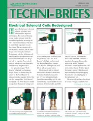
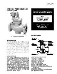
In addition, separate remote point solenoid valves arerequired, one <strong>f<strong>or</strong></strong> each purge point. These are not includedwith the APMC. The <strong>Hansen</strong> type HS8A solenoid valvehaving a 13mm p<strong>or</strong>t and a stainless steel piston is therecommended minimum p<strong>or</strong>t size. Below is a typicalpurge point solenoid valve with close-coupled strainer(Figure 9).Figure 10Figure 9STRAINER/ORIFICEBODYFULLYENCAPSULATED COILSTAINLESS STEELPISTONSTRAINER/ORIFICESCREEN ASSEMBLYCHECK VALVESThere are three check valves on the purger. A 5.5 bardifferential check valve is installed on the purge gas lineto prevent any possibility of reverse flow of water into thepurger. A 15.5 bar differential relief check valve leadsfrom the condensing coil inlet to the suction line; thisprevents excessive purger pressure. A third check valveis installed from the liquid drainer to the evap<strong>or</strong>at<strong>or</strong> coilto prevent reverse flow with a temp<strong>or</strong>ary loss of “foulgas” pressure.LIQUID DRAINERThe liquid drainer removes any condensed liquid thatdrains from the “foul gas” line into the purger. Thisenables the purger to always be condensing gas, ratherthan having liquid entering the condensing section of thepurger and limiting proper operation. The drainer solenoidvalve (A) will open to empty a reasonable amount of excessliquid directly to the flooded evap<strong>or</strong>at<strong>or</strong>. However, iftoo much liquid comes down the “foul gas” line, due toimproperly piped condensers, c<strong>or</strong>rective action must betaken. See the “Foul gas” piping section on page 1.STRAINER/ORIFICEThe strainer/<strong>or</strong>ifice meters condensed liquid refrigerantfrom the high-pressure side of the purger into its floodedevap<strong>or</strong>at<strong>or</strong>. It features a dual filter arrangement to reducepotential <strong>or</strong>ifice blockage. This dual filter (strainer)removes particles and houses the integral <strong>or</strong>ifice (strainer/<strong>or</strong>ifice screen assembly). See Figure 10.APMC-001aAPR 2008CLOSE-COUPLEDSTRAINERMANUAL OPENINGSTEM8WATER BUBBLER (AMMONIA SYSTEMS)F<strong>or</strong> ammonia systems, the APMC is equipped with awater bubbler which eliminates any water bottle attention.Purge gas (noncondensibles) from the purger flows intothe bottom of the water bubbler where residual ammoniacan be abs<strong>or</strong>bed into the water. The water with abs<strong>or</strong>bedammonia flows to a drain. The water solenoid valve (D)opens to automatically replenish water to the bubblereach time the purge gas solenoid valve (C) energizes. A30-second delay keeps the water solenoid valve (D) openafter the purge gas solenoid valve (C) de-energizes t<strong>or</strong>efill water bubbler. Proper release of noncondensiblesthrough the bubbler is usually indicated by large, 15 mmdiameter bubbles.AIR INDICATING COLUMN (HALOCARBONSYSTEMS)F<strong>or</strong> halocarbon systems, while the air indicating column(water bubbler flush system) is included, the water lineand drain line are not required. Fill the clear tube to themarked line with a lightweight, clear refrigeration oilNoncondensibles released from the purger bubble upthrough the column, indicating proper operation.
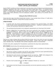
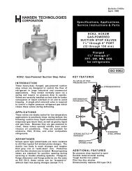
The APMC is designed to automatically start-up andoperate without the assistance of plant personnel.Beginning at start-up, the following is a description ofthe refrigerant flow through a purger. Keep the controlcabinet do<strong>or</strong> closed at all times to prevent waterdamage and tampering.<strong>PURGER</strong> START-UP SEQUENCEOn start-up, liquid refrigerant fills and begins to coolthe purger. The liquid line solenoid valve (B) energizesto feed refrigerant to the flooded evap<strong>or</strong>at<strong>or</strong>. The lowside level sens<strong>or</strong>, located on the side of the floodedevap<strong>or</strong>at<strong>or</strong>, senses when liquid reaches the proper level.The display should show 3333.At the same time the flooded evap<strong>or</strong>at<strong>or</strong> is filling, “foulgas” enters the flooded evap<strong>or</strong>at<strong>or</strong> condensing coil andthe refrigerant gas contained therein changes state toa liquid. The liquid and noncondensible gas graduallyfill the air separat<strong>or</strong> chamber.As the purger continues to cool down, a temperature sens<strong>or</strong>attached to the flooded evap<strong>or</strong>at<strong>or</strong> senses temperature.At approximately 5°C evap<strong>or</strong>at<strong>or</strong> temperature, the readoutwill no longer display 3333.“Foul gas” is continually processed as long as a remotepurge point solenoid is energized. It is imp<strong>or</strong>tant thatone, but only one, remote purge point solenoid valve isopen at all times to prevent losing “foul gas” pressure tothe purger. If “foul gas” pressure is lost (as sensed bypressure transducer), diagnostic code 2222 flashes onthe APMC digital readout. No purging of air will occuruntil “foul gas” pressure is rest<strong>or</strong>ed.SECTION 3 APMC OPERATIONFigure 11OPERATIONThe “foul gas” may carry a certain amount of condensedrefrigerant which is captured by the liquid drainer be<strong>f<strong>or</strong></strong>eit enters the flooded evap<strong>or</strong>at<strong>or</strong> coil of the purger. Thedrainer level sens<strong>or</strong> operates solenoid valve (A) todrain the liquid directly into the low-pressure floodedevap<strong>or</strong>at<strong>or</strong>. This separation step enables the liquidrefrigerant to bypass the purger’s flooded evap<strong>or</strong>at<strong>or</strong>condensing coil.The liquid-free “foul gas” enters the condensing coil,which is submerged in the cold liquid refrigerant of theflooded evap<strong>or</strong>at<strong>or</strong>. The refrigerant gas condenses whilethe noncondensible gas passes into the air separat<strong>or</strong>chamber. The condensed liquid refrigerant is removedfrom the air separat<strong>or</strong> chamber through the strainer withintegral <strong>or</strong>ifice, and passed into the low-pressure sideof the flooded evap<strong>or</strong>at<strong>or</strong>.Meanwhile, the noncondensible gas collects in the airseparat<strong>or</strong> chamber. The collected noncondensible gasgradually depresses the liquid level causing the highside level sens<strong>or</strong> to open both the purge gas solenoidvalve (C) and water solenoid valve (D). Inside the waterbubbler, noncondensible gas and water mix so thatresidual amounts of ammonia can be abs<strong>or</strong>bed. Thewaste water is flushed to an environmentally protecteddrain through the overflow tube.1/2" NPTWATER LINEFLOWCONTROLLERWATERBUBBLEROVERFLOWTUBEDFLANGES(TYPICAL)STRAINER13 MM FOULGAS LINELIQUIDDRAINER13 MM HIGH PRESSURELIQUID LINEHIGH SIDELEVEL SENSORCHECK VALVE(5.5 BAR)CHECKVALVEAC20 MM SUCTION LINEDRAINERLEVELSENSORTEMP.SENSORLOW SIDELEVELSENSORPRESSURE TRANSDUCERCONNECTION FORATMOSPHERICSAFETY RELIEF VALVEINTERNAL DIFFERENTIALPRESSURE RELIEF CHECKVALVE (15.5 BAR)FOUL GASPRESSUREGAUGEAIR SEPARATOR CHAMBERSOLENOID VALVES:A DRAINERB LIQUID LINEC PURGE GASD WATER LINEBSTRAINERFLOODED EVAPORATOR1" NPT PLASTIC PVCDRAIN TO SEWER3/8" NPT LOW SIDEOIL DRAIN ANDPUMPOUTSTRAINER/ORIFICELIQUID FEED LINE3/8" NPT HIGH SIDEOIL DRAIN AND PUMPOUT9APMC-001aAPR 2008
SECTION 4 APMC INTERFACEThe <strong>Hansen</strong> AutoPurger APMC Interface software allows<strong>f<strong>or</strong></strong> remote monit<strong>or</strong>ing of the APMC via a RS485 netw<strong>or</strong>k.The APMC has an ID range (00-07) allowing a maximumof 8 APMCs on a single netw<strong>or</strong>k. This allows the end userto add the APMC(s) to an existing netw<strong>or</strong>k <strong>or</strong> setup anetw<strong>or</strong>k as needed. RS485 allows multiple devices (upto 32) to communicate at half-duplex on a single twistedpair of shielded wires at distances up to 1200 meters.SYSTEM REQUIREMENTSIt is assumed that you already have Microsoft® Windows98/98SE, 2000 Professional <strong>or</strong> XP Home/Professionalinstalled on your <strong>PC</strong> and that you understand the basiclayout and functions of the Windows operating system.The HANSEN <strong>AUTO</strong><strong>PURGER</strong> APMC INTERFACE softwarew<strong>or</strong>ks on any Pentium class <strong>PC</strong> with the followingspecifications:− At least 1MB of free space on the hard drive <strong>f<strong>or</strong></strong>installation files− An additional 5 MB minimum free space on the harddrive is required <strong>f<strong>or</strong></strong> the log file if used− A Microsoft compatible mouse− VGA (<strong>or</strong> better) monit<strong>or</strong> set to a minimum screenresolution 800x600− CD-ROM− 16650 compatible serial p<strong>or</strong>t (COM p<strong>or</strong>t)− RS485 interface <strong>or</strong> RS232 interface with externalRS485 adapterHOST INTERFACERS-485 (half-duplex communications) @ 9600 bps, 1 start-,8 data- and 1 stop-bit and no parity. No handshaking issupp<strong>or</strong>ted. If the <strong>PC</strong> running the HANSEN <strong>AUTO</strong><strong>PURGER</strong>APMC INTERFACE software only contains an RS232interface then an external RS232 to RS485 convertercan be used to complete the communications. Followthe manufacture’s directions when configuring theexternal card.INSTALLATION AND SETUPThe HANSEN <strong>AUTO</strong><strong>PURGER</strong> APMC INTERFACE softwareis distributed as a single setup file. The setup file <strong>f<strong>or</strong></strong>HANSEN <strong>AUTO</strong><strong>PURGER</strong> APMC INTERFACE software isSETUP.EXEInstallation of the software is quick and simple. Just runthe setup file and follow the on screen instructions.Insert the CD into your CD-rom drive. The auto-run dialogwill automatically appear. If not, select START->RUN->BROWSE and navigate to the CD-ROM drive and runSETUP.EXE. Follow the on-screen setup instructions.PROGRAM OPERATIONOnce a connection is established, the HANSEN<strong>AUTO</strong><strong>PURGER</strong> APMC INTERFACE software will beginrequesting data from the APMC. First, temperature isrequested, followed by a request <strong>f<strong>or</strong></strong> the pressure, thenthe status in<strong>f<strong>or</strong></strong>mation and finally the log data.If an err<strong>or</strong> condition exists the log data is not requested.The err<strong>or</strong> code is displayed. Once the err<strong>or</strong> condition iscleared the HANSEN <strong>AUTO</strong><strong>PURGER</strong> APMC INTERFACEsoftware will request and display the log data.MENU BARFile Settings Connect HelpTo activate a menu, click on the menu title. When themenu appears, click the menu item.FILE CLEAR DATA:Clear displayed data in the log screen.FILESAVE DATA:Allows the user to specify a location and filename <strong>f<strong>or</strong></strong>the log file. The visible data in the log screen is writtento the log file.FILEEXIT:Exits the HANSEN <strong>AUTO</strong><strong>PURGER</strong> APMC INTERFACEsoftware.SETTINGSSET ID:Allows the user to select the system ID between 00-07. The APMC must be set to the same ID in <strong>or</strong>der tocommunicate. Refer to page 7 <strong>f<strong>or</strong></strong> further in<strong>f<strong>or</strong></strong>mation.The default setting is ID 0001.SETTINGSSERIAL PORT SETTINGS:Allows the user to select the appropriate communicationp<strong>or</strong>t (COMM 1 – COMM 5). Only the COMM p<strong>or</strong>t isselectable. Refer to the computer documentation <strong>f<strong>or</strong></strong>further in<strong>f<strong>or</strong></strong>mation. The default setting is COMM1.SETTINGS UNITS:Allows the user to specify the displayed units (Celsius/kPa <strong>or</strong> Fahrenheit/psig) <strong>f<strong>or</strong></strong> the Purger Temperature andCondensing Pressure. The default setting is Celsius/kPa.SETTINGSPOLLINGRATE:Allows the user to specify the amount of elapsed time(2 – 9 seconds) between requests <strong>f<strong>or</strong></strong> data. The defaultsetting is 4 seconds.CONNECTMAKE CONNECTION:Allows the user to establish communication with thePurger.HELPABOUT:Program version in<strong>f<strong>or</strong></strong>mation.COMMUNICATION FORMAT ANDCOMMANDSAll codes are represented in ASCII <strong>f<strong>or</strong></strong>mat.Communications with the APMC can be initiated byany device capable of sending the proper sequence ofcharacters.APMC-001aAPR 200810
Communication <strong>f<strong>or</strong></strong>mat:Request Data (Send): ID + Command CodeReply Data (Receive): ID + DataID (00-07) is specified as the least significant digit first.F<strong>or</strong> example an ID = 01 would be sent 10.Command Codes:Pressure ‘X’: Request pressure from the APMC (10X)Temperature ‘W’: Request temperature from the APMC(10W)Status ‘T’: Request status in<strong>f<strong>or</strong></strong>mation from the APMC(10T)Purge Log ‘V’: Request the Purge Log from the APMC(10V)Reset Zero ‘Z’: APMC will reset the Purge Log (10Z). N<strong>or</strong>eply is sent from the APMC.APMC Data Reply F<strong>or</strong>mat:Pressure reading is transmitted in 5, 8 bit ASCII w<strong>or</strong>dsbeginning with the 10ths digit followed by the decimalpoint, ones, tens, hundreds position and sign. Pressureis transmitted in psig only.Status codes plus Err<strong>or</strong> code are transmitted in 5,8-bit ASCII w<strong>or</strong>d.Front Panel LEDs State CodeON ON AON OFF B<strong>PURGER</strong> COOLING DOWN ON E<strong>PURGER</strong> COOLING DOWN OFF F<strong>AUTO</strong>MATIC PURGING ON F<strong>AUTO</strong>MATIC PURGING OFF EPURGING NONCONDENSIBLES ON CPURGING NONCONDENSIBLES OFF DERRORCODE7777 K6663 L6662 M6661 N5555 O4444 P3333 Q2222 RNo Err<strong>or</strong>sSReply F<strong>or</strong>mat: 105.521 (ID + Pressure)Example: Pressure reading of 125.5 psigASCII 1 2 5 . 5LastByteFirstByteTemperature reading is transmitted in 6, 8 bit ASCIIw<strong>or</strong>ds beginning with the 10ths digit followed by thedecimal point, ones, tens and hundreds position and sign.Temperature is transmitted in Fahrenheit only.EXAMPLEIf the APMC sends the following: 10ADFJS10 = Purger ID is “01”A = Purger is “ON”D = Purger is not releasing noncondensiblesF = Purger is in “<strong>AUTO</strong>MATIC PURGING” and is not“COOLING DOWN”J = Either an “I” <strong>or</strong> a “J” is transmitted in this position,but is not used and should be ign<strong>or</strong>edS = No err<strong>or</strong>sReply F<strong>or</strong>mat: 108.570 + (ID + Temperature)Example: Temperature reading of +75.8ºFASCII +(<strong>or</strong>)- 0 7 5 . 8LastByteFirstBytePurge Log reading is transmitted in 4, 8 bit ASCII w<strong>or</strong>dsbeginning with the ones position.Reply F<strong>or</strong>mat: 104321 (ID + Purge Log Minutes)Example: Purge log reading of 1234ASCII 1 2 3 4LastByteFirstByteSAMPLE SCREEN11APMC-001aAPR 2008
SECTION 5 TROUBLESHOOTING <strong>PURGER</strong> OPERATIONDIGITAL READOUT FLASHING 2222LOSS OF “FOUL GAS” PRESSURE. This usually meansthe pressure in the air separat<strong>or</strong> chamber is below 5.5bar. Pressure gauge on the purger reads near suctionpressure. The purger will not allow noncondensible gasesto be released from the purger. However, the purger willcontinue to operate n<strong>or</strong>mally in all other functions.REASON 1: A burned-out purge point solenoid coil.Check: Advance purge points one at a time waitingapproximately 2 minutes be<strong>f<strong>or</strong></strong>e advancing again. Waituntil the digital readout again flashes 2222. The faultycoil <strong>or</strong> wiring is now pinpointed.Action: Replace the coil <strong>or</strong> repair the wire.REASON 2: A remote purge point solenoid valve isjammed closed.Check: Inspect the remote purge point solenoid valvewhich caused the diagnostic code to appear. Manuallyopen the solenoid valve and recheck the pressure.Action: If the coil is energized, clean and replace anysolenoid valve parts as necessary. See also the Cautionsection on page 14.REASON 3: “Foul gas” line restricted.Check: Inspect the “Foul gas” line <strong>f<strong>or</strong></strong> a closed shut-offvalve(s) <strong>or</strong> the plastic shipping cap still in “foul gas”line flange.Action: Open shut-off valves and/<strong>or</strong> remove the shippingcap. See also Caution section, page 14.REASON 4: Faulty pressure transducer.Check: Check the pressure gauge reading on the APMC.If it is above 5.5 bar, check pressure transducer pluginconnect<strong>or</strong> terminals 27 & 30 <strong>f<strong>or</strong></strong> 10 volts DC. Thencheck terminals 28 & 29 <strong>f<strong>or</strong></strong> at least 13 mV.Action: If terminals 27 & 30 do not have 10 volts DC,check <strong>f<strong>or</strong></strong> faulty wiring. If terminals 28 & 29 do not haveat least 13 mV, replace the pressure transducer (p/n20-1857) with the purger at zero pressure. See alsothe Caution section on page 14.DIGITAL READOUT FLASHING 3333<strong>PURGER</strong> TOO WARM. If the purger evap<strong>or</strong>at<strong>or</strong>temperature is 5°C <strong>or</strong> warmer, the purger will not releasenoncondensible gas from the purger because excessiverefrigerant would also escape. The purger will continueto operate n<strong>or</strong>mally in all other functions. This code isalso displayed during initial start-up until the purgerflooded evap<strong>or</strong>at<strong>or</strong> is cooled down.REASON 1: Suction temperature too high.Check: Verify the pressure at the purger suction lineconnection.Action: Connect to a lower-temperature suction.REASON 2: Restriction in the suction line.Check: Inspect the suction line and shut-off valves.These should be a minimum size of 20 mm. On newinstallations, also make sure the plastic shipping capin suction line flange is removed.Action: Eliminate the restriction. See also the Cautionsection on page 14.REASON 3: The flooded evap<strong>or</strong>at<strong>or</strong> inside the purger isnot filled with refrigerant.Check: Look <strong>f<strong>or</strong></strong> a closed liquid line shut-off valve,Also, check that the liquid line solenoid valve (B) isenergized.Action: Open the liquid line shut-off valve. If notenergized, check <strong>f<strong>or</strong></strong> voltage at the liquid line solenoidvalve coil. Replace the coil if it is burned-out.REASON 4: Faulty temperature sens<strong>or</strong>.Check: With the temperature sens<strong>or</strong> plug-in connect<strong>or</strong>disconnected from power board (see Figure 4), checkthe electrical resistance of the sens<strong>or</strong> across the wireleads.Action : If the resistance is not between 30 K ohms and486 K ohms, replace the temperature sens<strong>or</strong> (p/n 20-2303). See also Caution section on page 14.DIGITAL READOUT FLASHING 4444PURGED OVER 60 MINUTE TIME LIMIT. Ifnoncondensibles are released from the purger <strong>f<strong>or</strong></strong> 60minutes continuously, a time delay will close the purgegas solenoid valve (C). This limits the possibility of asubstantial amount of refrigerant inadvertently beingreleased into the water bubbler in the unlikely event ofpurger malfunction.REASON 1: A large volume of noncondensibles iscontinuously being removed from system.Action: Reset the time delay by pressing the ZERORESET once. (See Figure 6). Delay is now reset <strong>f<strong>or</strong></strong> upto another hour of continuous purging.REASON 2: Purge gas solenoid valve (C) is not opening<strong>or</strong> the removable seat/<strong>or</strong>ifice is blocked.Check: Make sure purge gas solenoid valve (C) isenergized. If not, check <strong>f<strong>or</strong></strong> voltage at solenoid coil.Action: Replace the coil if it is burned-out, otherwiseclean <strong>or</strong> replace the removable seat/<strong>or</strong>ifice inside thesolenoid valve body. See also the Caution section onpage 14.REASON 3: The shut-off valve located be<strong>f<strong>or</strong></strong>e the purgegas solenoid valve (C) is closed.Check: Verify that purge gas is not being sent to thebubbler.Action: Open the valve.DIGITAL READOUT FLASHING 5555<strong>PURGER</strong> SHUT-OFF REMOTELY. This code indicatesthat the optional interlock remote relay contacts areopen. These contacts are connected to the purger via thepower/interlock plug-in connect<strong>or</strong> terminals 11 and 12.REASON 1: The purger is temp<strong>or</strong>arily shut-off due to theinterlocked compress<strong>or</strong> (<strong>or</strong> other device) being shutdown by temperature controls <strong>or</strong> safety devices.Check: Wait until the interlocked compress<strong>or</strong> (<strong>or</strong> otherdevice) begins to operate. If digital readout does notstop flashing diagnostic code 5555, then check theinterlock relay <strong>f<strong>or</strong></strong> proper operation.APMC-001aAPR 200812
DIGITAL READOUT FLASHING 6666LEVEL CONTROL OUT OF RANGE. This Flashing6666 code will alternate with either a 6661, 6662, <strong>or</strong>6663 code. The second code indicates which levelsens<strong>or</strong> is out of the n<strong>or</strong>mal sensing range. This mayindicate a mechanical <strong>or</strong> electrical problem with thedrainer level sens<strong>or</strong> (6661), the low side level sens<strong>or</strong>(6662), <strong>or</strong> the high side level sens<strong>or</strong> (6663).REASON 1: One <strong>or</strong> m<strong>or</strong>e level sens<strong>or</strong>s are out ofcalibration.Action: Recalibrate the level sens<strong>or</strong>s as follows:A) First, all liquid refrigerant and oil must be removedfrom the APM and the pressure must be zeroatmospheric pressure.B) Remove power to purger.C) Install the supplied “jumper” (small white chip) tothe Reset Pins located on the side of the ControlBoard. See Figure 4. Note: A small alligat<strong>or</strong> clipcan be substituted <strong>f<strong>or</strong></strong> “jumper”.D) Apply power to the APM. The display on the frontof the APM should read “CAL”. With power stillapplied, remove “jumper” from the Reset Pins.E) Recalibration is complete.REASON 2: Discontinuity in the coaxial wire from theprobe to the control board.Check: Verify that the level sens<strong>or</strong> coaxial connect<strong>or</strong>sat the control board are tight.Action: If the connections appear proper, replace thesuspected level sens<strong>or</strong>, with the purger isolatedfrom the system and pressure at zero. See also theCaution section on page 14.DIGITAL READOUT FLASHING 7777LOSS OF HIGH PRESSURE LIQUID. If the liquid linesolenoid valve remains energized <strong>f<strong>or</strong></strong> m<strong>or</strong>e than 30minutes, it indicates there is insufficient high-pressureliquid available to maintain an adequate level in theflooded evap<strong>or</strong>at<strong>or</strong> of the purger. The purger will notpurge air until this is c<strong>or</strong>rected.REASON 1: Liquid line solenoid valve (B) is not opening<strong>or</strong> the removable seat/<strong>or</strong>ifice is blocked.Check: Make sure the liquid line solenoid valve (B) isenergized. If not, check <strong>f<strong>or</strong></strong> voltage at the solenoidcoil.Action: Replace the coil if it is burned-out, otherwiseclean <strong>or</strong> replace the removable seat/<strong>or</strong>ifice inside thesolenoid valve body. See also the Caution sectionon page 14.REASON 2: Liquid line restricted.Check: Look <strong>f<strong>or</strong></strong> closed shut-off valves in the liquidline, plugged strainers, <strong>or</strong> the plastic shipping capstill in the liquid line flange.Action: Inspect piping <strong>f<strong>or</strong></strong> a closed shut-off valve. Openthe shut-off valves, clean the strainer, <strong>or</strong> removethe shipping cap. See also the Caution section onpage 14.REASON 3: Flooded evap<strong>or</strong>at<strong>or</strong> is full of oil.Check: Look <strong>f<strong>or</strong></strong> oil at the drain valves.Action: Drain the oil acc<strong>or</strong>ding to safe refrigerationpractices.<strong>PURGER</strong> NOT OPERATING AND THEDIGITAL READOUT BLANKREASON 1: One <strong>or</strong> both of the replaceable 3 amp fusesis blown.Check: Check <strong>f<strong>or</strong></strong> a blown fuse.Action: Replace the blown fuse.REASON 2: A sh<strong>or</strong>t <strong>or</strong> open on the low voltage side ofthe power board.Check: With power to the APMC use a voltmeter tocheck <strong>f<strong>or</strong></strong> approximately 10V DC across terminals 27and 30.Action: If there is no voltage across the terminals, replacethe power board. Refer to drawing 2001-80 <strong>f<strong>or</strong></strong> powerboard replacement procedures.REASON 3: One <strong>or</strong> both solid state fuses (F6A and F6B)are blown.Action: Disconnect power and verify continuity acrossthe fuses. Replace board if no continuity.NONCONDENSIBLES ARE NOT BEINGRELEASED.(See also page 12; Digital Readout Flashing 3333)REASON 1: Noncondensibles not present in system.Check: Compare the refrigerant liquid temperature fromcondenser exit with the condensing pressure. Thepressure/temperature relationship should be within0.15 to 0.20 bar.Action: None at this time.REASON 2: Strainer/<strong>or</strong>ifice plugged.Symptom: The purger appears to be operating properly,however, the liquid feed line is not frosted.Check: Look <strong>f<strong>or</strong></strong> a restriction in the strainer/<strong>or</strong>ifice.REASON 3: “Foul gas” line is flooded with liquid.Symptom: The line from the bottom of the liquid drainersolenoid valve (A) to the inlet of the purger evap<strong>or</strong>at<strong>or</strong>often remains frosted.Check: Inspect condenser and “foul gas” piping. Inmany cases, the problem is liquid refrigerant beingdrawn from the purge point. To prevent this fromhappening, select purge point locations above liquidsurfaces and make sure purge point lines are installedso that only vap<strong>or</strong>, and not liquid, can be drawn in.Refer to Figure 2.Action: C<strong>or</strong>rect condenser and “foul gas” piping.AMMONIA INSTEAD OFNONCONDENSIBLES RELEASED FROM<strong>PURGER</strong>.(See also page 12; Digital Readout Flashing 3333)REASON 1: Purge gas solenoid valve (C) leaking atseat.Symptom: A slow leak of noncondensibles to the bubblerwhen the Purging Noncondensibles light is off.Check: Look <strong>f<strong>or</strong></strong> dirt <strong>or</strong> a w<strong>or</strong>n seat in the purge gassolenoid valve (C).13APMC-001aAPR 2008
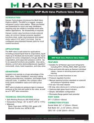
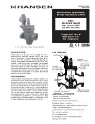
Action: Remove, clean, <strong>or</strong> replace the seat/<strong>or</strong>ifice andsolenoid tube plunger. See also the Caution sectionon page 14.REASON 2: Oil in purger.Symptom: No frost around the low side oil drain valve.Action: Remove oil through both the low side and highside drain valves (See Figure 1) per safe refrigerationprocedures and suggested oil removal instructionsdescribe in the Oil Drain section, page 4.WATER BUBBLER DEVELOPS EXCESSIVEMINERAL COATING.REASON 1: Hard water.Action: Add vinegar to the bubbler water. Then, cleanwith the supplied brush. Use a water conditioninghousing and cartridge in the water supply line to thepurger.DEFINITIONSNoncondensibles: Mostly air, this gas causes higherthan necessary head pressure. Typically air enters arefrigeration system through vacuum leaks, break downof oil and refrigerant, and during service repairs.“Foul gas”: A mixture of noncondensibles and refrigerantgas.P-trap: A piping arrangement, typically in condenserdrain lines, to prevent passage of gas while enablingliquid to proceed.High-pressure liquid: Refrigerant liquid source fromcondenser <strong>or</strong> receiver.Purge gas: The noncondensible result of the separationof refrigerant gas from the “foul gas” by the purger.Purge point: Represents a location on the refrigerationsystem from which “foul gas” is removed.Active purge point: Purge point from which the purgeris currently removing “foul gas”.Remote purge point solenoid valve: A solenoid valvelocated at a purge point.Water bubbler: A system by which the purge gas iscleaned of residual ammonia.Installation Categ<strong>or</strong>y (Overvoltage Categ<strong>or</strong>y) II:Product withstands impulse of 2500 Volts acc<strong>or</strong>dingto standardized impulse voltage levels per IEC 664.CAUTION<strong>Hansen</strong> purgers are only <strong>f<strong>or</strong></strong> refrigeration systems andmust not be used in a manner not specified herein. Theseinstructions and related safety precautions must be readcompletely and understood be<strong>f<strong>or</strong></strong>e selecting, using, <strong>or</strong>servicing these purgers. Only knowledgeable, trainedrefrigeration technicians should install, operate, <strong>or</strong> servicethese purgers. Purger should be disconnected fromthe power supply be<strong>f<strong>or</strong></strong>e servicing. Stated temperatureand pressure limits should not be exceeded. Purgercomponents should not be removed from the purgerunless the system has been evacuated to zero pressure.See also the Safety Precautions in current the List PriceBulletin and the Safety Precautions Sheet supplied withthe product. Escaping refrigerant may cause personalinjury, particularly to the eyes and lungs.WARRANTY<strong>Hansen</strong> electrical and electronic parts are guaranteedagainst defective materials and w<strong>or</strong>kmanship <strong>f<strong>or</strong></strong> 90 daysF.O.B. our plant. All other components are guaranteed<strong>f<strong>or</strong></strong> one year F.O.B. our plant. No consequential damages<strong>or</strong> field lab<strong>or</strong> is included.VPM, VALVE PACKAGE FOR AMMONIAVPMVPMF1/4 INCHNPTGAUGEVALVEFOUL GASLINE16 MMD/ODOPTIONAL VALVE PACKAGESFigure 12FOUL GAS LIQUID SUCTIONLINE LINE LINE13 MMSOCKETWELD13MMSOCKETWELD20 MMSOCKETWELDVPMF, VALVE PACKAGE FOR HALOCARBONSLIQUIDLINESUCTIONLINECUSTOMER SUPPLIED 16 MM D/ODCOPPER PIPE (TYPICAL)16 MMD/ODSHUT-OFF VALVE(VIEW ROTATEDFOR CLARITY)1/4 INCHNPTGAUGEVALVE<strong>PURGER</strong> FRAME20 MM SOCKET WELD1/4 INCHNPTGAUGEVALVE<strong>PURGER</strong> FRAMEAPMC-001aAPR 200814
PARTS LISTELECTRICALControl Board 20-2396Power Board 20-24713A (amp) fuse (5mm x 20mm) Type F<strong>f<strong>or</strong></strong> Power Board20-1698Cable, Control Board 20-1837Pressure Transducer 20-1857Temperature Sens<strong>or</strong> 20-2303High Side Level Sens<strong>or</strong>F<strong>or</strong> Ammonia 77-0534F<strong>or</strong> Halocarbons 77-0796Drainer & Low Side Level Sens<strong>or</strong>F<strong>or</strong> Ammonia 77-0535F<strong>or</strong> Halocarbons 77-0794Solenoid Coil Kit230V <strong>f<strong>or</strong></strong> DIN plug 70-1089115V <strong>f<strong>or</strong></strong> DIN plug 70-1088DIN plug connect<strong>or</strong> with gasket 70-0316MECHANICALSolenoid Tube/Plunger Kit 70-1059Water Solenoid Valve (D), Less Coil HS2B/1Water Bubbler <strong>f<strong>or</strong></strong> Ammonia 20-1959Air Indicating Column <strong>f<strong>or</strong></strong> Halocarbons 20-2282Strainer/Orifice Screen Assembly Kitincludes Strainer/Orifice ScreenAssembly and necessary O-RingsF<strong>or</strong> Ammonia Systems 20-2177F<strong>or</strong> Halocarbons Systems 20-2285Water Flow Controller 20-1985Removable Seat/Orifice KitsF<strong>or</strong> Solenoid Valve (A) 70-1069F<strong>or</strong> Solenoid Valve (B) Ammonia 70-1068F<strong>or</strong> Solenoid Valve (B) Halocarbon 70-1069F<strong>or</strong> Solenoid Valve (C) 70-10685.5 Bar Check Valve 20-2379Foul Gas/Liquid Line Strainer Kitsinclude Strainer Basket and O-Ring78-1010ORDERING INFORMATION, <strong>PURGER</strong>Cat. No.APMCAPMCFDescriptionAuto-Purger M <strong>f<strong>or</strong></strong> <strong>Plant</strong> <strong>Computer</strong>, <strong>f<strong>or</strong></strong>ammonia systemsAuto-Purger M <strong>f<strong>or</strong></strong> <strong>Plant</strong> <strong>Computer</strong>, <strong>f<strong>or</strong></strong>halocarbon systemsTo Order: Specify catalog number, refrigerant andvoltage. Standard voltage is 230V 50/60Hz, 115V 50/60Hzis available.ORDERING INFORMATION, OPTIONALVALVE ISOLATION PACKAGECat. No.VPMVPMFDescriptionValve Package <strong>f<strong>or</strong></strong> ammonia systemsValve Package <strong>f<strong>or</strong></strong> halocarbonsystemsTo Order: Specify catalog number and refrigerant. TheVPM optional isolation valve package consists of threeflanged welded assemblies which include the necessaryshut-off valves and gauge valves <strong>f<strong>or</strong></strong> the “foul gas” line,suction line, and liquid line. The VPMF <strong>f<strong>or</strong></strong> halocarbonsalso includes filter dryers and moisture indicating sightglasses.15APMC-001aAPR 2008
APMC-001aAPR 2008<strong>Hansen</strong> <strong>Technologies</strong> C<strong>or</strong>p<strong>or</strong>ation6827 High Grove BoulevardBurr Ridge, Illinois 60527 USATel: 630.325.1565 Fax: 630.325.1572 Toll: 800.426.7368Email: info@hantech.com Web: www.hantech.comUSA ∙ Asia ∙ Europe ∙ India ∙ Latin America ∙ Middle East© 2008 <strong>Hansen</strong> <strong>Technologies</strong> C<strong>or</strong>p<strong>or</strong>ation16