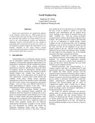
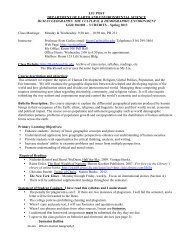
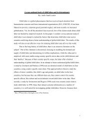
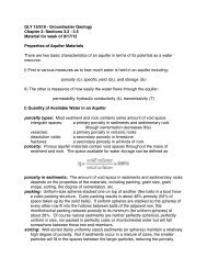
FeaturesPart of one of three detailed AutoCAD draw<strong>in</strong>gs of the C.W. <strong>Post</strong>campus used as a data source.A digital orthophotograph, show<strong>in</strong>g a portion of the C.W. <strong>Post</strong> campus,that can be downloaded from the New York State GIS Clear<strong>in</strong>ghouse.and verify features from the AutoCAD files. Thedata was separated <strong>in</strong>to the 12 shapefiles listed <strong>in</strong>Table 1.was used as a hard clip l<strong>in</strong>e <strong>in</strong> the triangulationprocess. The result<strong>in</strong>g TIN honors z-values onthe contour l<strong>in</strong>es; uses spot elevations (that wererepresented as two short, crossed l<strong>in</strong>e segmentson the contour layer <strong>in</strong> the AutoCAD draw<strong>in</strong>gs);and does not extrapolate z-values outside theedge of campus where detailed elevation datawas not available.Roads and sidewalks were mapped as polygonsrather than l<strong>in</strong>es to control the width of thePark<strong>in</strong>g lots, build<strong>in</strong>gs, and <strong>for</strong>ested areas werealso mapped as polygons. Initially, these fivepolygon layers were symbolized with appropriatetextures and colors and overlaid on theTIN on which a grass texture had been applied.However, when us<strong>in</strong>g this method, portions ofthe grass-textured TIN bled through the otherpolygon layers that obta<strong>in</strong>ed base height fromthe TIN. The result was that odd patches of grassappeared <strong>in</strong> places such as <strong>in</strong> the middle of aMak<strong>in</strong>g a Virtual CampusThe two-foot <strong>in</strong>terval contour l<strong>in</strong>es provideddetailed base elevation <strong>in</strong><strong>for</strong>mation <strong>for</strong> the entirecampus. The contours were converted <strong>in</strong>toa triangulated irregular network (TIN) to createa smooth, cont<strong>in</strong>uous surface across the campus.To create the TIN, the contours were used asmass po<strong>in</strong>ts and the campus boundary polygonroads. This also allowed surface textures, such asasphalt and concrete, to be applied <strong>in</strong> <strong>ArcScene</strong>.park<strong>in</strong>g lot where they were not actually present.Cont<strong>in</strong>ued on page 28
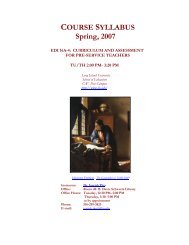
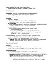
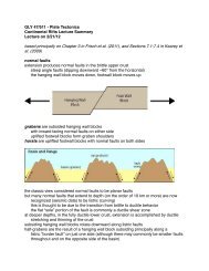
Virtual Campus 101Cont<strong>in</strong>ued from page 27This occurred even if the park<strong>in</strong>g lot polygonswere offset from or extruded above the TIN.Because nearly every feature that wasnʼtroad, park<strong>in</strong>g lot, sidewalk, <strong>for</strong>ested area, orbuild<strong>in</strong>g on the campus was grassy lawn, a landuse/land cover layer was created that assigned allareas on campus to one of these six categories.This elim<strong>in</strong>ated the display of random, phantomgrass. Also, sharp edges could be displayed betweenadjacent features by offsett<strong>in</strong>g one featuretype with respect to another. For example, theroads and park<strong>in</strong>g lots were offset by 0.3 meter(or approximately 1 foot) from the sidewalks,grassy areas, and <strong>for</strong>ested areas to create a discretewhite break between the two. In essence,this process created a virtual curb one foot high.By mapp<strong>in</strong>g the <strong>for</strong>ested areas as polygons,po<strong>in</strong>ts represent<strong>in</strong>g <strong>in</strong>dividual trees could begenerated at random locations with<strong>in</strong> the polygons.In this model, po<strong>in</strong>ts were generated us<strong>in</strong>ga dot density display <strong>in</strong> ArcMap and exportedas a po<strong>in</strong>t shapefile us<strong>in</strong>g a script obta<strong>in</strong>ed fromthe ESRI knowledge base. Virtual <strong>for</strong>ests <strong>for</strong> thiscampus were created us<strong>in</strong>g four different po<strong>in</strong>tfiles, each with a different dot density. This resulted<strong>in</strong> random po<strong>in</strong>t placement and the abilityto use four different types of trees that produced<strong>for</strong>ests with more variety: different species, sizes,and colors of trees.It was important <strong>for</strong> some po<strong>in</strong>t features to beoriented <strong>in</strong> a particular direction. For example,the bus stops had to face the street. To achievethis, a rotation field was added to the attributetable, us<strong>in</strong>g 0 to 360 degrees as the value range.Rotation values were entered <strong>for</strong> each featurethat needed adjustment and used to rotate the objects<strong>in</strong> <strong>ArcScene</strong>.To give the build<strong>in</strong>gs height, they were extrudedbased on height values from the attributetable. To capture the vary<strong>in</strong>g colors of theexterior walls, trim, and roofs of the build<strong>in</strong>gs,two more copies of the build<strong>in</strong>gs shapefile wereadded to the <strong>ArcScene</strong> project. The three identicalbuild<strong>in</strong>g layers were then offset vertically sothey would be layered on top of each other. Theextrusion values <strong>for</strong> each copy of the shapefilewere also adjusted so the build<strong>in</strong>gs would reta<strong>in</strong>their correct height. The polygons were thensymbolized with colors, based on exterior colorvalues from the attribute table. The result<strong>in</strong>gvariations of colors match the general exteriorcolors <strong>for</strong> each build<strong>in</strong>g on campus.Add<strong>in</strong>g More RealismTo add even more realism to the virtual campus,two additional shapefiles were created—one<strong>for</strong> cars and one <strong>for</strong> horses. Cars were placed <strong>in</strong>the park<strong>in</strong>g lots, and horses were placed <strong>in</strong> thehorse stables located on the campus. <strong>ArcScene</strong><strong>in</strong>cludes an array of three-dimensional objects,such as cars, trees, light posts, fire hydrants, andbus stops, that were used <strong>in</strong> this model. In thisrender<strong>in</strong>g, five different makes, models, and colorsof cars (available <strong>in</strong> <strong>ArcScene</strong>) were used toadd variety and detail to the model. All cars wereoriented based on park<strong>in</strong>g spaces on campus,with the necessary degree of rotation stored <strong>in</strong>the Rotation field of the attribute table.Import<strong>in</strong>g three-dimensional objects is simple.To add horses, po<strong>in</strong>ts <strong>in</strong> a new shapefilewere scattered around the stables. These po<strong>in</strong>tswere given various orientations specified <strong>in</strong> aRotation field <strong>in</strong> the attribute table. A free threedimensionalhorse model was downloaded fromthe Internet and added as a <strong>3D</strong> marker symbol.Fences <strong>in</strong> the stables area are numerous, butwere easily <strong>in</strong>cluded by sav<strong>in</strong>g l<strong>in</strong>e featureson the fence layer from the AutoCAD draw<strong>in</strong>gas a shapefile and then apply<strong>in</strong>g a <strong>3D</strong> texturel<strong>in</strong>e symbol represent<strong>in</strong>g a rail fence from the<strong>ArcScene</strong> <strong>3D</strong> symbols.Right: A portion of the <strong>3D</strong> campusmodel that shows different land use/landcover features <strong>in</strong> close proximity. Theroads and park<strong>in</strong>g lots are offset onefoot below the grassy areas, <strong>for</strong>estedareas, and sidewalks. A rotation valueis assigned to the bus stop to properlyorient it with respect to the road.Where to Go from HereAdditions and ref<strong>in</strong>ements can be made to anyvirtual model. However, it is possible the C.W.<strong>Post</strong> campus model may generate more <strong>in</strong>terestand foster more participation on campus <strong>in</strong> itscurrent state rather than a more realistic version.Nonetheless, there is a long wish list of enhancements<strong>for</strong> this model. The use of three-di-Right: The stables on campus with a<strong>3D</strong> model of a horse <strong>in</strong>cluded at severallocations. The complex pattern of fenceswas easily imported from the AutoCADdraw<strong>in</strong>g of the campus. These fences canbe displayed with <strong>3D</strong> texture l<strong>in</strong>e symbolsso gaps between the fence rails aretransparent.Right: Three copies of the build<strong>in</strong>gsshapefile were added to the displayand assigned colors to represent walls,trim, and roofs. Heights were extrudedso that the three build<strong>in</strong>g layers arestacked on each other and take <strong>in</strong>to accountthe height of each build<strong>in</strong>g.28 ArcUser April–June 2005 www.esri.com