1-Piece, Tight-Fit Molding - Laminators Inc.
1-Piece, Tight-Fit Molding - Laminators Inc.
1-Piece, Tight-Fit Molding - Laminators Inc.

Create successful ePaper yourself
Turn your PDF publications into a flip-book with our unique Google optimized e-Paper software.
Tech Support: 800.523.2347<strong>Laminators</strong><strong>Inc</strong>.com
TABLE OF CONTENTS Tech Support: 800.523.23471-<strong>Piece</strong>, <strong>Tight</strong>-<strong>Fit</strong> <strong>Molding</strong><strong>Laminators</strong>’ 1-<strong>Piece</strong>, <strong>Tight</strong>-<strong>Fit</strong> Extruded <strong>Molding</strong> System requires no prefabrication. Panel installationis easy and economical. <strong>Molding</strong>s can either be color-matched or a contrasting color; caulk is hiddenwithin the extrusions.Before You Start 1Preparing the WallInstallation Over Plywood Sheathing 2Installation Over Gypsum with Water-Resistive Barrier 3Installation Over Hat Channels or Furring Strips 4Mounting the Panels 5 – 7Essential Equipment and Supplies 8Additional AccessoriesInside Back CoverOmega-Lite PanelMaintenanceRoutine cleaning:Omega-Lite panels should be washed periodically tokeep them bright. Plain water and a clean cloth areall you need to remove ordinary dirt buildup. A mild,non-abrasive household detergent with a clean-waterrinse can be used for more stubborn stains. Solventssuch as alcohols, mineral spirits, naphtha, turpentine,and xylene can be applied with a soft cloth. Never soakpanels in solvents. You can safely use mineral spirits toremove uncured caulk and paints.For scratches and rub-marks:Omega-Lite touch-up paint and re-paintinstructions are available from <strong>Laminators</strong>.For larger paint repairs, call <strong>Laminators</strong> forstandard paints designed for aluminumsurfaces available at paint stores.Panels with MetallicPaint Finishes:The protective masking on the face of each panel shouldbe left in place until work is complete on any given areaof an installation. However, to help ensure good coloruniformity, periodically remove the masking from halfof a panel (peel masking upward from the bottom of thepanel) to check for color, scratches, and dents.On panels with metallic finishes, a good color match ismuch more difficult to achieve. In this case, two adjoiningpanels should be periodically checked by removingthe masking from half of two panels as the installationprogresses. The masking should then be taped back overthe panel to protect it.Should any defects be found, stop work immediatelyand call <strong>Laminators</strong> for assistance.When installing panels with metallic finishes, it isvery important that the directional arrows on thepanel masking are oriented in the same direction.Color variation is a characteristic of aluminumcomposite panels with metallic paint finishes.<strong>Laminators</strong> <strong>Inc</strong>orporated DOES NOT warrant acolor match for these panels.
<strong>Laminators</strong><strong>Inc</strong>.comSubstrate and FramingPrior to installation, the installer MUST verify that theframing and substrate are in compliance with allarchitects’ specifications.Inspect BOTH primary and secondary wall framing to verifythat all girts, angles, channels, studs and sheathing, andother structural panel support members and anchoragehave been installed within the following tolerances:1/4" in any 20' length vertically or horizontally1/2" in any building elevationInspect sheathing to verify that sheathing joints aresupported by framing and that installation is withinflatness tolerances. These surfaces must be even, smooth,sound, clean, and dry. If the substrate or framing is notwithin architectural specifications, the installer mustsubmit a written report to the General Contractor listingconditions that are detrimental to the installation ofpanels. Do NOT proceed with installation untilunsatisfactory conditions have been corrected.Summary of Installer ResponsibilityThe Panel Installer assumes total responsibility for allcomponents of the panel installation including, but notlimited to attachment to sub-construction, panel-to-paneljoints, joints between panels and dissimilar material, andthe joint seal associated with the panel system.Installation Supplies & AccessoriesSee page 8 to be sure you are using materials that havebeen tested and approved by <strong>Laminators</strong> for use withOmega-Lite panels. Inventory all materials and accessoriesto ensure that all materials are available on-site. Call TechSupport if you need additional recommendations.Receiving and StorageExamination: Upon receipt of materials, perform a thoroughexamination to identify any damage that may have occurredduring shipping. Any damage must be noted on the bill oflading at the time of receipt.Storage: Panels are to be stored horizontally on pallets witha positive slope for drainage of water and should be coveredwith watertight and ventilated materials. Standing water willdamage panel finish.No more than 1500 pounds should be stacked on onepallet. Depending on panel size, this should be fewer than50 panels at 30 pounds per panel and less than 2-1/2 'high. Do not stack other materials on or in contact withpanels to prevent staining, denting, or other damage.Storage temperature must not exceed 120ºF (49ºC).<strong>Laminators</strong>’ warranty does not cover water damage causedby improper storage or installation. Inspect panels ondelivery, then store them on skids 8" above the ground.Place a breathable cover over them and store them in aventilated space under roof.If wet panels are discovered, uncrate them and dry themwith towels to prevent wood rotting, paint staining, oraluminum corrosion.BEFORE YOU STARTPanel HandlingUse clean work gloves to avoid hand injury from any sharpedges and to prevent smudging of the prefinished surfaces.Although panels are shipped with protective masking onboth sides, always lift one panel completely off the nextto prevent scratches. Do not slide one panel across another.Protect panels from construction hazards. Goodconstruction practice provides for panel protection andcleaning in the contract documents. Normally these are thegeneral contractor’s responsibility. Temporary protectionmay be required if welding, cutting, sandblasting, orother potentially damaging construction activities arescheduled nearby.Cutting the PanelsOmega-Lite panels are designed to be cut to size onthe job site. Even if the panels have been received cutto size, it may be necessary to do some minor trimmingto account for areas of an elevation that may be out ofsquare. To cut Omega-Lite panels, use a circular saw witha sharp, carbide-tipped blade (40-tooth minimum).Do not remove the protective masking from the panel face.After cutting, use a screwdriver or deburring tool (seepage 8) to remove burrs or sharp edges from the panels.Carbide-tippedblade (40 tooth min.)recommendedSafety tip: Wear safety glasses when cutting!Wear gloves when handling cut edges!Ventilation is ImportantThe wood or exterior gypsum board of the substratemust be protected and ventilated. Trapped moisture cancause major damage in a short time. When mounting overexterior gypsum or masonry, use steel strapping or hatchannels to separate panels from the structure for goodair circulation.Flashing<strong>Laminators</strong> can supply flashing materials made fromaluminum sheet painted to match the adjacent panelsystem or surface.Use proper flashing technique when installing flashingwith panels.Complete CAD details and productspecifications can be downloaded fromour website <strong>Laminators</strong><strong>Inc</strong>.com1
PREPARING THE WALL Tech Support: 800.523.2347Installation Over Plywood SheathingAPaneladhesiveBack leg ofVertical “H”-<strong>Molding</strong>has been cut awayto accept Horizontal“H”-<strong>Molding</strong>Foam tape“H”-<strong>Molding</strong>Back leg ofVertical “H”-<strong>Molding</strong>has been cut awayto accept Horizontal“H”-<strong>Molding</strong>Detail A“H”-<strong>Molding</strong>24" O.C.Flashing /Ice & Water Shield“H”-<strong>Molding</strong>“J”-<strong>Molding</strong>Flashing /Ice & Water Shield“J”-<strong>Molding</strong>or drip edge“H”-<strong>Molding</strong>B1/4" above gradePlan ViewNote: Butt joint shown.Detail B2This installation process is the basis for mountingpanels over a variety of substrates. You should read andunderstand this process before attempting to mountpanels over other substrates such as plywood coveredwith water-resistive barrier, exterior gypsum with waterresistivebarrier, etc.In all cases, the same elements must be present:1) A structural surface, such as plywood, that willhold mechanical fasteners, such as screws.2) A surface that can be bonded to withpanel adhesive.If these two elements are not present, additional stepsmust be taken to provide them. Exterior grade gypsum,water-resistive barrier, or block walls are examples ofsubstrates that will require additionalpreparation before panels can be mounted. Thesesubstrates are covered in this manual.The main drawing (upper left) depicts the layoutfor one panel at ground level. “J”-molding is shown:either “J”- or drip edge moldings can be used here.The detail drawings (Detail A & B) show close-updetails from the main drawing. The instructions onpage 5 explain this process and the purpose of eachelement shown in the above drawings. When usingreveal “H”-moldings, apply color-matched caulkwhere the horizontal and vertical joints meet.Note: To guard against water penetration, <strong>Laminators</strong> recommendsthat all these installation systems include a water-resistivebarrier (appropriate for the climate and wall construction)installed on the substrate behind the metal wall panels.Follow installation instructions as shown on page 5.
<strong>Laminators</strong><strong>Inc</strong>.comPREPARING THE WALLInstallation Over Gypsum with Water-Resistive BarrierAPaneladhesive“H”-<strong>Molding</strong>WATER-RESISTIVEBARRIERBack leg ofVertical “H”-<strong>Molding</strong>has been cut awayto accept Horizontal“H”-<strong>Molding</strong>Foam tapeBack leg ofVertical “H”-<strong>Molding</strong>has been cut awayto accept Horizontal“H”-<strong>Molding</strong>“H”-<strong>Molding</strong>Detail A24" O.C.“H”-<strong>Molding</strong>WATER-RESISTIVEBARRIERFlashing /3" x 3"Ice & Water ShieldSteel squaresPlan View Note: Butt joint shown. “J”-<strong>Molding</strong>BFlashing /Ice & Water Shield“J”-<strong>Molding</strong>or drip edge1/4" above gradeDetail B“H”-<strong>Molding</strong>When installing panels over exterior gradegypsum, with water-resistive barrier, rememberthat neither exterior grade gypsum nor waterresistivebarrier are structural.For proper installation, 18 or 20 gauge steelsquares must be used to create a surface that willaccept panel adhesive.All steel squares must be attached with lowprofile,pan head screws at all four corners. Thesescrews must pass through the steel squares, theexterior grade gypsum, and attach to the studwall. <strong>Molding</strong>s must be attached through thegypsum to the studs.If moldings do not fall on top of steel stud, steelstrapping must be installed behind the extrusion.Strapping must be attached to the studs.The main drawing (upper left) depicts the layoutfor one panel at ground level. “J”-molding is shown:either “J”- or drip edge moldings can be used here.The detail drawings (Detail A & B) show close-updetails from the main drawing. The instructions onpage 5 explain this process and the purpose of eachelement shown in the above drawings. When usingreveal “H”-moldings, apply color-matched caulkwhere the horizontal and vertical joints meet.Follow installation instructions as shown on page 5.3
PREPARING THE WALL Tech Support: 800.523.2347Installation Over Hat Channels or Furring StripsAGap fordrainagePaneladhesiveHat channelBack leg ofVertical“H”-<strong>Molding</strong> hasbeen cut awayto accepthorizontal“H”-<strong>Molding</strong>“H”-<strong>Molding</strong>Back leg of Vertical“H”-<strong>Molding</strong> has beencut away to accepthorizontal “H”-<strong>Molding</strong>“H”-<strong>Molding</strong>Foam tapeDetail A24" O.C.“H”-<strong>Molding</strong>Flashing /Ice & Water ShieldFlashing /Ice & WaterShield“J”-<strong>Molding</strong>“J”-<strong>Molding</strong>or drip edge“H”-<strong>Molding</strong>B1/4" above gradePlan ViewNote: Butt joint shown.Detail BAgain, the drawing above depicts the layoutfor one panel at ground level. As with previoussubstrates, “J”-molding is shown at ground level.Either “J”-molding or drip edge moldings can beused here.Hat channels are used for installing panels oversurfaces such as brick or masonry that, whilestructural, cannot directly accept the <strong>Tight</strong>-<strong>Fit</strong><strong>Molding</strong> System. Hat channels can also be usedto create additional depth behind the panels ifrequired. Hat channels should be 3" wide acrossthe face and a minimum of 1/2" in depth.The main drawing (upper left) depicts the layoutfor one panel at ground level. “J”-molding is shown:either “J”- or drip edge moldings can be used here.The detail drawings (Detail A & B) show close-updetails from the main drawing. The instructions onpage 5 explain this process and the purpose of eachelement shown in the above drawings. When usingreveal “H”-moldings, apply color-matched caulkwhere the horizontal and vertical joints meet.4
www.<strong>Laminators</strong><strong>Inc</strong>.comMOUNTING THE PANELSInstalling the <strong>Molding</strong>sSet up a clean worktableUsing available materials (straight 2x4s, 3/4" flat soundplywood with smooth surface, or MDF plywood for precisionwork) construct a worktable at least 48" x 96" and at acomfortable working height. Place a strip of 2" masking tapealong the short edge of the worktable. This will enable you toclean any excess caulk off the tabletop. To keep the panel frommoving, drive two stop-screws into the tabletop at the endopposite the masking tape.1/8"minimumStep 1: Attach bottom molding to substrateSnap a level line at 1/4" above ground level (or more) as determinedby site supervision. Keeping the molding 1/4" above ground level,use galvanized drywall screws to attach the molding to the substrate.Fasten one screw per hat channel or furring strip on verticals, and onescrew every 16" to 24" O.C. on horizontals. Ice and water shield isrecommended to prevent water from getting to the wall at ground level.This is shown in Detail B on page 2 and 3.See manufacturer’s instructions for the proper use of ice and water shield.“H”-<strong>Molding</strong>Step 2: Cut away intersecting moldingThe dotted line shown in the drawing indicates an area wheretwo moldings will intersect. This area must be cut away so thatafter installation, moldings will sit on the same plane. An areaapproximately 4" should be adequate for the entire intersection.Use tin snips to cut the area to be removed. You may score theback of the “J”-molding at the bottom to keep extra flush againstplywood. Using sheet metal pliers (duck-bill vice grips), bend thematerial up and down until the piece snaps off.<strong>Piece</strong> cutaway fromthe corner“J” or drip edgeStep 3: Attach vertical moldingScrew moldings down as close to intersections as possible toensure that everything sits flat. Countersink galvanizeddrywall screws.VerticalmoldingPanelStep 4: Cut the first panel to sizeMeasure and cut the first panel to size. Deduct 1/8" from thepanel size to allow for expansion and contraction. Dry fit thepanel to make sure it fits properly.5
MOUNTING THE PANELSTech Support: 800.523.2347MaskingStep 5: Remove panel maskingRemove the masking from the back of the panel. Pull themasking back about 6" from all edges in the front of the panelbut do NOT remove it completely.Step 6: Apply Foam TapeApply foam tape to the substrate as instructed on pages 2through 4. This will help to prevent panel “suck in” when theadhesive cures.Foam tapePaneladhesiveSheathingPaneledge2x6Step 7: Apply caulk to moldingsUsing a <strong>Laminators</strong>-approved silicone caulk, run enough caulkinto the moldings so it will seal the edges when the panel isinserted. Use a 1/4" diameter (approx.) bead and be sure thatthere are no skips in the caulk. Fill the corner molding withcaulk. Caulk molding one panel at a time.Step 8: Apply panel adhesiveApply beads of <strong>Laminators</strong>-approved panel adhesive (See liston page 8) to the furring strips, sheathing, steel squares orhat channels as appropriate, using generous 3" wide dabsstaggered every 16" O.C. The adhesive should go between thestrips of foam tape and must make contact with back of panel.Refer to panel adhesive and caulk manufacturers’ working timesbefore applying to ensure proper adhesion.Step 9: Install first panelSlide the panel sideways into the pre-caulked outside corneror edge molding. If necessary, use wide blade putty knives tofit the panel into the vertical molding. Measure to be surethe panel is completely inserted into the molding.If necessary, nudge the panel into place using a 2x6as shown and tap it with a hammer to prevent damageto the panel edge.1/8" space forexpansion andcontractionStep 10: Install top moldingIf molding is required at the top of the first row of panels,leave 1/8" space for expansion and contraction. Fill themolding with caulk to seal the panels and attach it alongthe top edge of the panel. The shims provide space for panelexpansion caused by weather changes or direct sunlight.6
www.<strong>Laminators</strong><strong>Inc</strong>.comMOUNTING THE PANELSStep 11: Install next moldingTake the next vertical molding piece, caulk the short leg,and fasten the long leg of the “H” or reveal molding usingrecommended fasteners.Non-markingscraperStep 12: Continue panel installationRemove excess caulk with a non-marking plastic scraper.Mineral spirits and a clean rag should be used to remove anyresidue that the scraper missed.Continue installing panels until the job is completed. Coverthe top of the panels with a temporary tarp to keep water outif a parapet or flashing detail is to be installed at a later date.Remove masking from the front of the panels.CPlace panelCaution: All the masking must be removed within 2 weeks, otherwise it mayaffect the appearance of the panel and may be difficult to remove.Note: Remember to remove any shims from under the bottom molding wheninstallation is completed.Installation summary:BAttachoutsidecornerAAttachdrip edgeDPlace& attach“H”-moldingA. Attach drip edge moldings fastened every 12" withrecommended fasteners.B. Attach outside corner molding making sure to notch theback of the corner molding to allow the drip-edge to lieflush against the wall.C. Install panel. Be sure masking has been removed from backof the panel.D. Place and attach “H”-molding.FastenerWallSiliconebacker rodWallEnd-of-run detailFor 1-<strong>Piece</strong>, <strong>Tight</strong>-<strong>Fit</strong> moldings, fill an “H”-molding withcaulk. Attach it to the final edge, then install the finalpanel to complete the run.Caulk1-<strong>Piece</strong>“H”-molding, short sideto the end-of-run7
ESSENTIAL EQUIPMENT Tech Support: 800.523.2347• Work table or saw horses and 3/4" particle boardto create work table• Aluminum brake capable of bending 0.032" aluminum• Porter-Cable 3 HP router with guide or equivalentable to accept a 1/2" carbide shank• <strong>Laminators</strong>’ router bit (Part #RB 1/2)— Custom designed router bit only available from<strong>Laminators</strong> <strong>Inc</strong>. that forces bending into themiddle of the groove and eliminates core showthrough.Carbide with 1/2" shank.• Miter saw or chop saw with 10" diameter blade• Circular saw with 7-1/4", 40-tooth blade (min.)• Jigsaw with 24-tooth, sheet metal cutting blade• Caulking gun• Screw gun• Long 1/8" drill bit with drill bit plastic guard tubing• Deburring tool (Part #DEBURRING TOOL)• Aviation snips or heavy-duty scissors• Plastic putty tool or scraper to remove excess caulkand adhesive from panels• Metal single cut rectangular file with medium teeth• Utility knife• Tape measure• Safety glasses• Gloves to handle panelsESSENTIAL SUPPLIES• Panels• <strong>Molding</strong>s/extrusions as needed— “J” extrusion for drip edge (required)and end of run option (optional)— “H” extrusion for end of run option (optional)— snap-in extrusions (required)• Color-matched flat stock• Strapping— 0.40" aluminum or 20 ga. galvanized exteriorsheet metal strips 3" x 8', 10', or 12'• Furring strips or studs as needed• Insulation, 3/4" foam to go between furring strips• Ice & water shield or flashing• Gaska Tape® V710, 3/16" x 2" or equivalent closed cell7 lb. density polyvinyl chloride foam tape(<strong>Laminators</strong> Part #12847)• Silicone Caulk–The following caulks have been testedand meet requirements. Color-matched caulk availablefrom <strong>Laminators</strong> <strong>Inc</strong>.— Tremco Spectrem® 1— Dow Corning® 790, 983, 795, 995, 756, 791— GE SilGlaze® II , SilPruf®— Pecora 860, 896, 895, 890NSTNote: Minimum order quantities required forcertain color-matched caulks.• Caulking rope or backer rod; use 1/4" or 3/8" to suit job• Masking tape (Scotch brand Safe Release Masking Tapeis recommended) 1" wide• Panel Adhesive–The following adhesives havebeen tested and meet requirements. Variousadhesives available from <strong>Laminators</strong> <strong>Inc</strong>.— Titebond® Heavy-Duty Construction Adhesiveor Premium Polyurethane Construction Adhesive— Liquid Nails® 602 Subfloor (LN-602), 950Polyurethane (LN-950), 902 for Subfloor (LN-902),or 901 for Heavy Construction (LN-901)— DAP 4000 Subfloor Adhesive— OSI Sealants PL400• Screws— #6 x 1-1/4" bugle-head drywall or #8 or #10 x 1"Phillips Pan Head for securing clips into sheathing— #8 or #10 x 3/4" or longer, TEKS/3 screws to secureclips into steel studs— #6 x 1/2" and #6 x 1" Phillips Pan Head,TEKS/2 screws for mounting moldingsto plywood or metal• Wood shims to assist with spacing between panels• Mineral spirits and rags to clean caulk from panelsif necessary• Touch-up paintNote: Trademarks are registered by the companies noted.How Much Will I Need?For every 100 sq. ft. of Omega-Lite panelsyou will need:• 3 tubes 11 oz. silicone caulk• 1 tube 28 oz. panel adhesive• 1 roll 2" x 50' closed cell PVC foam tape8
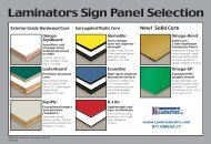
ADDITIONAL ACCESSORIES Tech Support: 800.523.23471-<strong>Piece</strong>, <strong>Tight</strong>-<strong>Fit</strong> <strong>Molding</strong>...for use with Omega-Lite panelsItem 4525X: Inside Corner (Drip Cap)Item 4535X: Adjustable (Bendable) Outside CornerItem 4595X: Reveal “H”-<strong>Molding</strong>Item 4505X: “H”-<strong>Molding</strong>Item 4515X: “J”-<strong>Molding</strong>Item 4545: “Z”-<strong>Molding</strong>The letter “X” identifies the molding color.4515X:“J”-<strong>Molding</strong>4545: “Z”-<strong>Molding</strong>Available plastic snap-inFascia Soffit or Outside Corner (“J”-<strong>Molding</strong> & “Z”-<strong>Molding</strong>combined with plastic snap-in molding)
<strong>Laminators</strong><strong>Inc</strong>.com Tech Support: 800.523.2347 3255 Penn Street · Hatfield, PA 19440©2012 <strong>Laminators</strong> <strong>Inc</strong>orporated. All rights reserved. A120 (7/12) Omega-Lite® Aluminum Building Panels Installation Guide.