Metal Bellows Couplings Servo-Insert Couplings Line Shafts
Metal Bellows Couplings Servo-Insert Couplings Line Shafts
Metal Bellows Couplings Servo-Insert Couplings Line Shafts
- No tags were found...

Create successful ePaper yourself
Turn your PDF publications into a flip-book with our unique Google optimized e-Paper software.
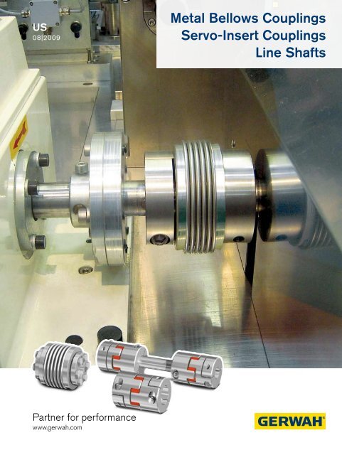
US08|2009<strong>Metal</strong> <strong>Bellows</strong> <strong>Couplings</strong><strong>Servo</strong>-<strong>Insert</strong> <strong>Couplings</strong><strong>Line</strong> <strong>Shafts</strong>Partner for performancewww.gerwah.com
A Global Presence For YouThe RINGFEDER POWER TRANSMISSIONGMBH was founded in 1922 in Krefeld, Germanyto fabricate and promote Friction Spring technology.Today we have expanded our offerings totop power transmission and damping products.Innovative thinking sets us apart and allows us todevelop progressive and economical solutions tosupport our customers.2
Special applicationsrequire special solutionsOur extensive range of RINGFEDER POWERTRANSMISSION products can be applied to solvemost applications. We don´t just sell, but by understandingthe individual requirements of our customers(e.g. loads on thecomponents, easy installation/removalcapabilityand reduction of productioncosts) assist you inevery step with innovativeengineering to planefficient and technicallymature solutions.3
Overview<strong>Metal</strong> <strong>Bellows</strong> <strong>Couplings</strong><strong>Servo</strong>-<strong>Insert</strong> <strong>Couplings</strong><strong>Line</strong> <strong>Shafts</strong>4
Content02 Pages Corporate Image<strong>Line</strong> <strong>Shafts</strong>04 Overview05 Content<strong>Metal</strong> <strong>Bellows</strong> <strong>Couplings</strong>06 Basics11 Product Overview12 Series EKN14 Series DKN16 Series DKN/S18 Series PKN20 Series AKN22 Series AKD24 Series AK26 Series CKN45 Basics47 Product Overview48 Series ADS-ZW50 Series ADS/B-ZW52 Series ASS/A-ZW54 Series ASS/B-ZW56 Series ADS/H-ZW58 Series AKN-ZWMounting Instructions60 <strong>Metal</strong> <strong>Bellows</strong> <strong>Couplings</strong>62 <strong>Servo</strong>-<strong>Insert</strong> <strong>Couplings</strong>66 <strong>Line</strong>-<strong>Shafts</strong><strong>Servo</strong>-<strong>Insert</strong> <strong>Couplings</strong>28 Basics31 Product Overview32 Series EK/GS34 Series DK/GS36 Series ADS38 Series ADS/R40 Series ASS/A42 Technical Information44 Preview: ICL & SMCFax Inquiry68 Fax Inquiry <strong>Couplings</strong>69 Fax Inquiry <strong>Line</strong> <strong>Shafts</strong>71 Delivery ProgramRINGFEDER POWER TRANSMISSIONAll technical details and information are non-binding and cannot be used as a basis for legal claims. The user is obligated to determine whether the represented products meethis requirements. We reserve the right at all times to carry out modifications in the interests of technical progress. Upon the issue of this catalogue all previous brochures andquestionnaires on the products displayed are no longer valid.5
<strong>Metal</strong> <strong>Bellows</strong> <strong>Couplings</strong> BasicsBacklash-free <strong>Metal</strong> <strong>Bellows</strong> <strong>Couplings</strong>Characteristics of<strong>Metal</strong> <strong>Bellows</strong> <strong>Couplings</strong>:Backlash-free transmission of torqueHigh torsional stiffness, precision of transmission ofrotational angleDifferent torsional stiffnessBacklash-free shaft connection<strong>Metal</strong> bellows made of stainless steelSimple and safe assemblyCompensation of radial, axial and angular misalignmentFree of wear, maintenance-free, no downtimesNot sensitive to temperatures between -22 F°and 212 F°Nominal torques between 13.3 – 44000 lb-in6
<strong>Metal</strong> <strong>Bellows</strong> <strong>Couplings</strong> BasicsBacklash-free <strong>Metal</strong> <strong>Bellows</strong> <strong>Couplings</strong> are used in applicationswhere maintaining torsional rigidity between two shafts is critical.Pumps with axial and vertical drivesHigh dynamic portal drivesSpindle lifting units<strong>Line</strong>ar unitsPackaging machinesMachine toolsSpecial machines7
Technical Information · <strong>Metal</strong> <strong>Bellows</strong> <strong>Couplings</strong>Design / Sample CalculationCoupling Design/ General informationBacklash-free torsionally stiff <strong>Metal</strong> <strong>Bellows</strong> <strong>Couplings</strong> are installationready when delivered. The metal bellows are made of stainlesssteel, other parts are made of aluminum or steel with some partshaving an environmentally friendly protective coating. Bores aresupplied with the ISO H7 tolerance standard, and we recommendthat shafts have the g6 transition fit tolerance. Please see the chartbelow for conversion to the ANSI standard. The backlash for otherfits may not exceed 0.0004 – 0.002.Torque is generated between the coupling hub and the shaft bycompression and friction on the contact surfaces. Special attentionshould be given to the correct tightening torque on the clampscrews as well as the condition of the shaft and hub bore surfaces.The contact surfaces must be free of oil and grease and the shaftmust have a surface roughness ≤ RMS 63. Keyways can also besupplied upon request to metric or imperial standards.Torque capacities published are based on strictly following our guidelines.Coupling Selection<strong>Metal</strong> <strong>Bellows</strong> couplings are generally selected based on nominaltorque needed for the application, Tkn in our tables. The nominaltorque must always be higher than the running torque. Thisgenerally applies for applications involving servo motors whoseacceleration torque in both forward and reverse directions exceedthe nominal torque. For applications involving controlled, highlydynamic drives, the following safety factors have proven to bereliable in practice:K= 1.5 for steady torquesK=2.0 for intermittent torquesK=2.5-4 for oscillating torquesFor servo drives in machine tools: k=1.5-2.0We would be pleased to design your metal bellows coupling for you.Feel free to use our experience and know-how for your success.Give us a call!T KN ≥ K x T AS xJ MachJ Mtr x J Mach= [lb-in]<strong>Servo</strong> driveSliding carriage<strong>Metal</strong> <strong>Bellows</strong> CouplingBall bearing spindle8
Technical Information · <strong>Metal</strong> <strong>Bellows</strong> <strong>Couplings</strong>Design in consideration of dynamic torsionalstiffnessAlthough metal bellows couplings are backlash-free and torsionallyrigid, keep in mind that the coupling links two rotating masses. Inadverse cases the coupling can act like a torsion spring with highstiffness. The regulating oscillation of the drives and the harmonicoscillation in the armature current of the motor therefore must neverbe within the range of the mechanical resonance frequency. Inpractice the resonance frequency “f res ” must be twice as high asthe excitation frequency of the drive.The dynamic torsional stiffness C Tdyn was selected so that it wouldnot be within the range of parasitic oscillation of most applications.Various levels of torsional stiffness are available as standard versions.We would be pleased to design your metal bellows couplings foryou. Feel free to use our experience and know-how for your success.Give us a call !Calculation for the application of a metal bellows coupling in a machine tool driveDrive related data forservo motor/FT 5104:Peak torque T AS = 1416 lb-inMoment of inertiaJ Mtr = 16.2 x 10 -2 lb-in-s 2The low moment of inertia for the metal bellows coupling isdisregarded. K = Load factor, impulse factor selected for thisdrive K = 2;Output data for Moment of inertia of ball screw andmachine tool: slide: J Mach = 15 x 10 -2 lb-in-s 2f res =1 2πC Tdyn xJ Mtr + J MachJ Mtr x J Mach= [Hz]Design according to torque:Coupling selection:AKD 200, T KN = 1770 lb-in, C Tdyn = 1027 x 103 lb-in/radThe metal bellows coupling is selected sufficiently,since 1770 lb-in > 1363 lb-inT KN ≥ K x T AS xJ MachJ Mtr + J Mach= 2 x 1416 lb-in x15 x 10 -2 lb-in-s 2(16.2 + 15) x 10 -2 lb-in-s 2 = 1363 lb-inDesign according to the resonance frequency:The arithmetic calculation is clearly higher thanthe expected resonance frequencyf res =1 2πC Tdyn xJ Mtr + J MachJ Mtr x J Mach= 1 2π x 1027000 lb-in/rad x 0.162 + 0.15 lb-in-s 20.162 x 0.15 lb-in-s 2 = 580 Hz9
Conveyor
Overview <strong>Metal</strong> <strong>Bellows</strong> <strong>Couplings</strong>SeriesEKNSeriesDKNSeriesDKN /SSeriesPKN<strong>Metal</strong> <strong>Bellows</strong> Couplingwith radial set-screws<strong>Metal</strong> <strong>Bellows</strong> Couplingwith clamping hubs<strong>Metal</strong> <strong>Bellows</strong> Couplingwith clamping hubs andexpanding clamps<strong>Metal</strong> <strong>Bellows</strong> Couplingwith detachable clampinghub for easier assemblyPage 12Page 14Page 16Page 18SeriesAKNSeriesAKDSeriesAKSeriesCKN<strong>Metal</strong> <strong>Bellows</strong> Couplingwith clamping hubs andshort length<strong>Metal</strong> <strong>Bellows</strong> Couplingwith clamping hubs<strong>Metal</strong> <strong>Bellows</strong> Couplingwith integral keyless lockingdevice<strong>Metal</strong> <strong>Bellows</strong> Couplingwith adaptor flangePage 20Page 22Page 24Page 2611
Ø D1 H7L+ -0.08Ø D2 H7Ø A120°Technical DataT KN = Nominal torqueC t = Dynamic torsional stiffness∆Kr = Max. approved misalignment radial∆Ka = Max. approved misalignment axial∆Kw = Max. approved misalignmentangularJ = Moment of inertiaM A = Tightening torque of screwsn max = Max. rotational speedICG ISO 4029 (DIN 916)Sectional viewTechnical DataSize T KN M A C t n max ∆ Ka ∆ Kw ∆ Kr WeightJlb-in 10 3 lb-in/rad rpm ± Inch Degrees Inch lbs 10 -3 lb-in 24 4 4 2213/1682/1328 15000 0.008/0.012/0.016 1.2/2/2 0.004/0.006/0.008 0.013 0.689 8 4 4426/3364/2655 15000 0.008/0.012/0.016 1.2/2/2 0.004/0.006/0.008 0.013/0.015/0.018 0.68/0.79/0.8915 13 13 6639/6196 15000 0.010/0.016 1.2/2 0.004/0.006 0.037/0.042 2.56/2.7320 18 13 13277/11507/8852 15000 0.012/0.016/0.020 1.2/2/2 0.004/0.008/0.010 0.049/0.053/0.057 4.78/5.47/5.8145 40 27 57536/35406 15000 0.012/0.020 1.2/2 0.004/0.008 0.119/0.128 23.2/24.9100 89 27 71698/59306 15000 0.016/0.020 1.2/2 0.006/0.010 0.229/0.251 68.4/75.2Fittings: Hubs: Standard fit H7Keyways: Standard fit JS9Materials:Hubs made of aluminium<strong>Metal</strong> bellows made of stainless steelSpecial designs : Coupling completely made of stainlesssteel (on request)Keyway acc. to DIN 6885-1 or ANSI B17.113
Backlash-free <strong>Metal</strong> <strong>Bellows</strong> CouplingSeries DKNDimensionsøA = Outer diameterøD1 H7 = Bore diameterøD2 H7 = Bore diameterøH = Clearance diameterC = Guided length shaft boreG = Clamping screwsI = Radius to clamp screwK = Radius to clamp screwL+ -0.08 = Total lengthC 1 = Bore tolerance for D 1C 2 = Bore tolerance for D 2DimensionsSize L Ø A Ø H Ø D1 H7 C1 Ø D2 H7 C2 C K I G±0.079 Inch mm4 0.83/0.94/1.10 0.63 0.71 0.12-0.310.12-0.310.28 0.20 0.08 M29 0.91/1.02/1.18 0.63 0.71 0.12-0.31 0.12-0.31 0.28 0.20 0.08 M215 1.02/1.18 0.79 0.83 0.12-0.39 -0 0.12-0.39 -0 0.35 0.28 0.12 M2.520 1.26/1.50/1.65 0.98 1.06 0.12-0.47 +0.001 0.12-0.47 +0.001 0.43 0.35 0.16 M345 1.61/1.97 1.30 1.34 0.24-0.63 0.24-0.63 0.51 0.47 0.20 M4100 1.85/2.24 1.57 1.65 0.24-0.75 0.24-0.75 0.55 0.63 0.20 M4Moment of inertia and weight (mass) are calculated with reference to the largest bore size.Example:DKNSeriesSizeLengthBore-Ø D1Bore-Ø D2Furtherdetails*DKN 20/1.65 0.250 0.375 XX14
Ø D1 H7IL+ -0.08G ISO 4762 (DIN 912)Ø D2 H7Ø AØ HKTechnical DataT KN = Nominal torqueC t = Dynamic torsional stiffness∆Kr = Max. approved misalignment radial∆Ka = Max. approved misalignment axial∆Kw = Max. approved misalignment angularJ = Moment of inertiaM A = Tightening torque of screwsn max = Max. rotational speedCSectional viewTechnical DataSize T KN M A C t n max ∆ Ka ∆ Kw ∆ Kr Weight Jlb-in 103 lb-in/rad rpm ± Inch Degrees Inch lbs 10 -3 lb-in 24 4 3 2213/1682/1328 15000 0.008/0.012/0.016 1.2/2/2 0.004/0.006/0.008 20 0.899 8 3 4426/3364/2655 15000 0.008/0.012/0.016 1.2/2/2 0.004/0.006/0.008 20/22/24 0.89/0.99/1.0915 13 7 6639/6196 15000 0.010/0.016 1.2/2 0.004/0.006 49/53 3.76/4.1020 18 9 13277/11507/8852 15000 0.012/0.016/0.020 1.2/2/2 0.004/0.008/0.010 79/84/88 8.54/9.23/9.5745 40 27 57536/35406 15000 0.012/0.020 1.2/2 0.004/0.008 163/172 33.49/35.20100 89 27 71698/59306 15000 0.016/0.020 1.2/2 0.006/0.010 265/287 79/85Fittings: Hubs: Standard fit H7Keyways: Standard fit JS9Materials: Hubs made of aluminium<strong>Metal</strong> bellows made of stainless steelsSpecial designs : Coupling completely made of stainlesssteel (on request)Keyway acc. to DIN 6885-1 or ANSI B17.115
Backlash-free <strong>Metal</strong> <strong>Bellows</strong> CouplingSeries DKN/SDimensionsøA = Outer diameterøD1 H7 = Bore diameterøD2 f7 = Clamp diameterøH = Clearance diameterC = Guided length shaft boreG = Clamping screwsG1 = Clamping screwI = Radius to clamp screwJ = Clamp lengthK = Radius to clamp screwL ± 0.08 = Total lengthC 1 = Bore tolerance for D 1C 2 = Bore tolerance for D 2DimensionsSize L C J Ø A Ø H Ø D1 H7 C1 Ø D2 H7 C2 K I G G1±0.079 Inch mm4 1.14/1.22/1.38 0.28 0.31 0.63 0.71 0.12-0.310.310.20 0.08 M2 M39 1.18/1.30/1.46 0.28 0.31 0.63 0.71 0.12-0.31 0.31 0.20 0.08 M2 M315 1.46/1.61 0.35 0.47 0.79 0.83 0.12-0.39 -0 0.39 -0 0.28 0.12 M2.5 M420 1.61/1.85/2.01 0.43 0.47 0.98 1.06 0.12-0.47 +0.001 0.39 +0.001 0.35 0.16 M3 M445 2.05/2.40 0.51 0.63 1.30 1.34 0.24-0.63 0.55 0.47 0.20 M4 M5100 2.40/2.80 0.55 0.79 1.57 1.65 0.24-0.75 0.63 0.63 0.20 M4 M6Moment of inertia and weight (mass) are calculated with reference to the largest bore size.Example:DKN/SSeriesSizeLengthBore-Ø D1Furtherdetails*DKN/S 20/1.61 0.375 XXIn this version, the expandable adaptor shaft, (length J anddiameter D2) can be expanded to clamp internally inside the matingcomponent. Simply by tightening the socket head cap screw G1the expandable sleeve clamps inside the component, therebytransmitting torque backlash-free from one shaft to the other.16
Technical DataØ AØ D1 H7IL+ -0.08JG ISO 4762 (DIN 912)Ø D2 f7Ø HKT KN = Nominal torqueC t = Dynamic torsional stiffness∆Kr = Max. approved misalignment radial∆Ka = Max. approved misalignment axial∆Kw = Max. approved misalignment angularJ = Moment of inertiaM A = Tightening torque of screwsn max = Max. rotational speedCG1 ISO 4762 (DIN 912)Sectional viewTechnical DataSize T KN M A C t n max ∆ Ka ∆ Kw ∆ Kr Weight Jlb-in 10 3 lb-in/rad rpm ± Inch Degrees Inch lbs 10 -3 lb-in 24 4 3 2213/1682/1328 15000 0.008/0.012/0.016 1.2/2/2 0.004/0.006/0.008 24 1.039 8 3 4426/3364/2655 15000 0.008/0.012/0.016 1.2/2/2 0.004/0.006/0.008 26/29/29 1.0315 13 7 6639/6196 15000 0.010/0.016 1.2/2 0.004/0.006 53/55 3.76/4.1020 18 9 13277/11507/8852 15000 0.012/0.016/0.020 1.2/2/2 0.004/0.008/0.010 84/90/93 7.18/7.86/8.5445 40 27 57536/35406 15000 0.012/0.020 1.2/2 0.004/0.008 183/196 27.34/29.39100 89 27 71698/59306 15000 0.016/0.020 1.2/2 0.006/0.010 287/324 78.27/87.49Fittings: Hubs: Standard fit H7ExpandingClamps: Standard fit f7Keyways: Standard fit JS9Materials:Hubs made of aluminium<strong>Metal</strong> bellows made of stainless steelSpecial designs: Coupling completely made of stainlesssteel (on request)Keyway acc. to DIN 6885-1 or ANSI B17.117
Backlash-free <strong>Metal</strong> <strong>Bellows</strong> CouplingSeries PKNDimensionsøA = Outer diameterøD1 H7 = Bore diameterøD2 H7 = Bore diameterøH = Clearance diameterC = Guided length shaft boreG = Clamping screwsI = Radius to clamp screwK = Radius to clamp screwL ± 0.08 = Total lengthN = Basic dimensionC 1 = Bore tolerance for D 1C 2 = Bore tolerance for D 2DimensionsSize L N Ø A Ø H Ø D1 H7 C1 Ø D2 H7 C2 C K I G±0.079 Inch mm2 1.50 0.35 0.98 1.10 0.12/0.470.12/0.350.43 0.35 0.16 M34.5 1.85 0.35 1.30 1.38 0.24/0.63 0.24/0.63 0.51 0.47 0.20 M410 2.09 0.35 1.57 1.65 0.24/0.75 0.24/0.75 0.55 0.63 0.20 M418 2.74 0.43 1.77 1.89 0.39/0.98 -0 0.39/0.75 -0 0.79 0.71 0.24 M530 2.80 0.59 2.17 2.20 0.39/0.98 +0.001 0.39/0.87 +0.001 0.98 0.79 0.31 M660 3.44 0.79 2.60 2.64 0.55/1.38 0.55/0.98 1.14 0.94 0.39 M880 4.00 0.87 3.15 3.35 0.79/1.57 0.79/1.50 1.34 1.10 0.47 M10150 4.00 0.87 3.15 3.35 0.79/1.57 0.79/1.50 1.34 1.10 0.47 M10Moment of inertia and weight (mass) are calculated with reference to the largest bore size.Example:PKNSeriesSizeBore-Ø D1Bore-Ø D2Furtherdetails*PKN 150 1.125 1.375 XXOne split clamping hub can be separated from the couplingfor easier assembly such as when two components need to beconnected in a blind hole. Simply mount one side of the couplingon one shaft and the other side of the couple on the oppositeshaft and slide them together.18
Ø D1 H7IL-1NN/2N/2Ø D2 H7Ø AG ISO 4762 (DIN 912)Ø HKTechnical DataT KN = Nominal torqueC t = Dynamic torsional stiffness∆Kr = Max. approved misalignmentradial∆Ka = Max. approved misalignment axial∆Kw = Max. approved misalignment angularJ = Moment of inertiaM A = Tightening torque of screwsn max = Max. rotational speedCSectional viewTechnical DataSize T KN M A C t n max ∆ Ka ∆ Kw ∆ Kr Weight Jlb-in 10 3 lb-in/rad rpm ± Inch Degrees Inch lbs 10 -3 lb-in 22 18 9 8.59 22900 0.016 1.2 0.008 0.1 0.0074.5 40 27 42.5 17600 0.012 1.2 0.004 0.2 0.01010 89 27 53.1 14100 0.016 1.2 0.006 0.2 0.01418 159 53 53.1 12700 0.020 1.5 0.008 0.4 0.01830 266 106 230 10200 0.016 1 0.004 0.6 0.04260 531 266 496 8600 0.016 1 0.004 1.1 0.11180 708 531 859 6800 0.016 1 0.008 2.2 0.302150 1328 752 991 6800 0.016 1 0.008 2.2 0.302Fittings: Hubs: Standard fit H7Keyways: Standard fit JS9Materials:Hubs made of aluminium<strong>Metal</strong> bellows made of stainless steelSpecial designs : Coupling completely made of stainlesssteel (on request)Keyway acc. to DIN 6885-119
Backlash-free <strong>Metal</strong> <strong>Bellows</strong> CouplingSeries AKNDimensionsøA = Outer diameterøD1 H7 = Bore diameterøD2 H7 = Bore diameterøH = Clearance diameterC = Guided length shaft boreG = Clamping screwsI = Radius to clamp screwK = Radius to clamp screwL ± 0.08 = Total lengthC 1 = Bore tolerance for D 1C 2 = Bore tolerance for D 2DimensionsSize L Ø A Ø H Ø D1 H7 C1 Ø D2 H7 C2 C K I G T KN±0.079 Inch lb-in18 2.48 1.77 1.89 0.39-0.980.39-0.980.79 0.71 0.24 M5 15930 2.56 2.17 2.20 0.39-0.98 0.39-0.98 0.98 0.79 0.31 M6 26660 3.07 2.52 2.64 0.55-1.26 0.55-1.26 1.14 0.94 0.39 M8 53180 3.54 3.15 3.31 0.79-1.57 -0 0.79-1.57 -0 1.30 1.10 0.47 M10 708150 3.54 3.15 3.31 0.79-1.57 +0.001 0.79-1.57 +0.001 1.30 1.10 0.47 M10 1328200 3.90 3.54 3.66 0.98-1.73 0.98-1.73 1.50 1.22 0.51 M12 1770300 4.09 4.33 4.33 1.26-1.97 1.26-1.97 1.50 1.54 0.51 M12 2655500 4.37 4.69 4.80 1.57-2.36 1.57-2.36 1.61 1.69 0.59 M14 4426Moment of inertia and weight (mass) are calculated with reference to the largest bore size.Example:AKNSeriesSizeLengthBore-Ø D1Bore-Ø D2Furtherdetails*AKN 150 1.125 1.375 XX20
Ø D1 H7IL+ -0.08 KG ISO 4762 (DIN 912)Ø D2 H7Ø AØ HTechnical DataT KN = Nominal torqueC t = Dynamic torsional stiffnessCr = Radial spring stiffnessCa = Axial spring stiffness∆Kr = Max. approved misalignment radial∆Ka = Max. approved misalignment axial∆Kw = Max. approved misalignment angularJ = Moment of inertiaM A = Tightening torque of screwsn max = Max. rotational speedCSectional viewTechnical DataSize M A C t Cr Ca n max ∆ Ka ∆ Kw ∆ Kr Weight Jlb-in 10 3 lb-in/rad 10 3 lb-in/rad rpm ± Inch Degrees Inch lbs lb-in 218 53 71 1770 443 12700 0.020 1.5 0.008 0.4 0.1730 106 310 6373 443 10200 0.016 1 0.004 0.6 0.3860 266 664 9737 797 8600 0.016 1 0.004 1.0 0.9980 531 1151 10622 708 6800 0.016 1 0.008 2.2 2.97150 752 1328 17703 1328 6800 0.016 1 0.008 2.2 2.97200 885 1505 22129 1328 6300 0.016 1 0.008 2.6 4.92300 1062 4426 55765 2478 5900 0.016 1 0.008 3.0 10.3500 1682 6019 77894 885 4900 0.020 1 0.008 3.8 16.1Fittings: Hubs: Standard fit H7Keyways: Standard fit JS9Materials:Hubs made of aluminium<strong>Metal</strong> bellows made of stainless steelSpecial designs : Coupling completely made of stainlesssteel (on request)Keyway acc. to DIN 6885-121
Backlash-free <strong>Metal</strong> <strong>Bellows</strong> CouplingSeries AKDDimensionsøA = Outer diameter total couplingøD1 H7 = Bore diameterøD2 H7 = Bore diameterøH = Clearance diameterC = Guided length shaft boreG = Clamping screwsI = Radius to clamp screwK = Radius to clamp screwL ± 0.08 = Total lengthC 1 = Bore tolerance for D 1C 2 = Bore tolerance for D 2DimensionsSize L Ø A Ø H Ø D1 H7 C1 Ø D2 H7 C2 C K I G±0.079 Inch18 2.80 1.77 1.85 0.39-0.980.39-0.980.79 0.71 0.24 M530 2.87 2.17 2.20 0.39-0.98 0.39-0.98 0.98 0.79 0.31 M660 3.50 2.52 2.64 0.55-1.26 0.55-1.26 1.14 0.94 0.39 M880 4.06 3.15 3.31 0.79-1.57 -0 0.79-1.57 -0 1.34 1.10 0.47 M10150 4.06 3.15 3.31 0.79-1.57 +0.001 0.79-1.57 +0.001 1.34 1.10 0.47 M10200 4.45 3.54 3.66 0.98-1.73 0.98-1.73 1.50 1.22 0.51 M12300 4.53 4.29 4.33 1.26-1.97 1.26-1.97 1.50 1.54 0.51 M12500 4.80 4.69 4.80 1.57-2.36 1.57-2.36 1.61 1.69 0.59 M14Moment of inertia and weight (mass) are calculated with reference to the largest bore size.Example:AKDSeriesSizeBore-Ø D1Bore-Ø D2Furtherdetails*AKD 150 1.125 1.375 XX22
Ø D1 H7ICL+ -0.08 KG ISO 4762 (DIN 912)Ø D2 H7Ø AØ HTechnical DataT KN = Nominal torqueC t = Dynamic torsional stiffnessCr = Radial spring stiffnessCa = Axial spring stiffness∆Kr = Max. approved misalignmentradial∆Ka = Max. approved misalignment axial∆Kw = Max. approved misalignmentangularJ = Moment of inertiaM A = Tightening torque of screwsn max = Max. rotational speedSectional viewTechnical DataSize T KN M A C t Cr Ca n max ∆ Ka ∆ Kw ∆ Kr Weight Jlb-in 10 3 lb-in/rad 10 3 lb-in/rad rpm ± Inch Degrees Inch lbs lb-in 218 159 53 53 752 354 12700 0.02 1.5 0.008 0.4 0.2130 266 106 221 1947 266 10200 0.02 1.5 0.008 0.6 0.3460 531 266 443 2921 487 8600 0.02 1.5 0.008 1.0 1.0380 708 531 664 3541 487 6800 0.02 1.5 0.008 2.2 3.08150 1328 752 885 5311 752 6800 0.02 1.5 0.008 2.2 3.08200 1770 885 1062 3983 752 6300 0.02 1.5 0.008 2.6 5.13300 2655 1062 2478 13277 1328 5900 0.02 1.5 0.008 3.1 10.9500 4426 1682 2744 8852 752 4900 0.04 1.5 0.008 4.0 16.7Fittings: Hubs: Standard fit H7Keyways: Standard fit JS9Materials:Hubs made of aluminium<strong>Metal</strong> bellows made of stainless steelSpecial designs: Coupling completely made of stainlesssteel (on request)Keyway acc. to DIN 6885-123
Backlash-free <strong>Metal</strong> <strong>Bellows</strong> CouplingSeries AKDimensionsøA = Outer diameter total couplingøB = Outer diameter HubøD1 H7 = Bore diameterøD2 H7 = Bore diameterøT = Pitch circle diameterE = Overall length - relaxed condiotionG = ScrewsJ = Coupling Body length - relaxed conditionL ± 0.08 = Total lengthC 1 = Bore tolerance for D 1C 2 = Bore tolerance for D 2DimensionsSize L Ø A ØB Ø T Ø D1 H7 Ø D2 H7 E J G±0.079 Inch mm30 2.05/2.36 2.20 2.17 1.22/1.22 0.47-0.79 0.47-0.79 1.77/2.09 1.18/1.50 6xM460 2.48/2.87 2.60 2.52 1.46/1.46 0.59-0.98 0.59-0.98 2.17/2.56 1.38/1.81 6xM680 3.11/3.58 3.23 3.15 2.01/2.01 0.94-1.38 0.94-1.38 2.83/3.27 1.93/2.40 6xM6150 3.11/3.58 3.23 3.15 2.01/2.01 0.94-1.38 0.94-1.38 2.83/3.31 1.93/2.40 6xM6200 3.15/3.66 3.54 3.54 2.01/2.20 0.94-1.57 0.94-1.57 2.83/3.35 1.97/2.48 6xM6300 3.66/4.09 4.33 4.29 2.44/2.95 0.98-1.97 0.98-1.97 3.15/3.66 2.20/2.64 6xM8500 4.02/4.45 4.80 4.69 3.15/3.15 1.57-2.17 1.57-2.17 3.70/4.13 2.40/2.83 6xM8800 6.69 6.18 5.51 3.62/3.94 1.97-2.76 1.97-2.76 5.91 4.33 6xM161400 6.69 6.18 5.51 3.62/3.94 1.97-2.76 1.97-2.76 5.91 4.33 6xM163000 8.11 6.18 5.51 4.53 2.76-3.15 2.76-3.15 7.48 5.91 6xM125000 8.11 8.19 6.85 3.94/4.92 2.36-3.35 2.36-3.35 7.32 5.75 6xM16Moment of inertia and weight (mass) are calculated with reference to the largest bore size.Example:AKSeriesSizeLengthBore-Ø D1Bore-Ø D2Furtherdetails*AK 150/3.15 1.125 1.375 XX24
L+ -0.08Technical DataT KN = Nominal torqueC t = Dynamic torsional stiffnessCr = Radial spring stiffnessCa = Axial spring stiffnessØ AØ TØ D1 H7JØ D2 H7Ø BG ISO 4017 (DIN 933)∆Kr = Max. approved misalignmentradial∆Ka = Max. approved misalignment axial∆Kw = Max. approved misalignmentangularJ = Moment of inertiaM A = Tightening torque of screwsn max = Max. rotational speedESectional viewTechnical DataSize T KN M A C t Cr Ca n max ∆ Ka ∆ Kw ∆ Kr Weight Jlb-in 10 3 lb-in/rad 10 3 lb-in/rad rpm ± Inch Degrees Imch lbs lb-in 230 266 27 310/221 6373/1947 443/266 11000 0.016/0.020 1/1.5 0.004/0.008 0.9 0.5160 531 75 664/443 9736779/2921034 797/443 9100 0.016/0.020 1/1.5 0.004/0.008 1.8 0.8280 708 89 1151/664 10622/3541 708/443 7000 0.016/0.020 1/1.5 0.008/0.008 2.9 2.22150 1328 124 1328/885 17703/5311 1328/752 7000 0.016/0.020 1/1.5 0.008/0.008 2.9 2.22200 1770 124 1505/1062 22129/3983 1328/752 6700 0.016/0.020 1/1.5 0.008/0.008 3.5 2.97300 2655 159 4426/2478 55765/13277 2478/1328 5200 0.016/0.020 1/1.5 0.008/0.008 7.5 7.96500 4426 230 6019/2744 77894/8852 885/752 4600 0.020/0.039 1/1.5 0.008/0.008 10 19.6800 7081 398 6727 4514 1682 3700 0.039 1.5 0.008 22 891400 12392 708 11507 6285 2478 3700 0.039 1.5 0.008 22 893000 26555 752 24785 26112 2744 2800 0.039 1.5 0.008 33 1645000 44258 1859 42488 43550 4514 2800 0.039 1.5 0.008 46 212Fittings: Hubs: Standard fit H7Materials: Hubs made of aluminium (Size 30 – 500)Hubs made of steel (Size 800 – 5000)<strong>Metal</strong> bellows made of stainless steelLocking device made of steelSpecial designs : Coupling completely made of stainlesssteel (on request)25
Backlash-free <strong>Metal</strong> <strong>Bellows</strong> CouplingSeries CKNDimensionsøA = Outer diameter total couplingøB = Outer diameter HubøD1 H7 = Bore diameterøD2 H7 = Bore diameterøT = Pitch circle diameterM = Max. screw-in depthG = Fixing boreL ± 0.08 = Total lengthDimensionsSize L Ø A Ø B ØT Ø D1 H7 ; Ø D2 H7 M G±0.079 Inch mm18 1.42/1.73 1.81 1.81 1.22 0.87 0.24 6xM530 1.18/1.50 2.20 2.17 1.46 1.10 0.28 6xM560 1.61/2.01 2.60 2.52 1.81 1.50 0.39 6xM680 2.05/2.44 3.23 3.15 2.44 1.97 0.51 6xM6150 2.05/2.44 3.23 3.15 2.44 1.97 0.51 6xM6200 2.01/2.48 3.54 3.54 2.44 1.97 0.51 6xM6300 2.17/2.60 4.33 4.29 3.15 2.56 0.51 6xM8500 2.40 4.80 4.69 3.70 2.76 0.63 6xM8800 5.12 6.18 5.98 4.33 3.35 0.71 6xM161400 5.12 6.18 5.98 4.33 3.35 0.71 6xM163000 5.31 6.18 5.98 4.33 3.35 0.87 6xM165000 5.71 8.19 8.19 5.12 3.94 0.98 6xM16Example:CKNSeriesSizeLengthBore-Ø D1Bore-Ø D2Furtherdetails*CKN 150/2.05 1.97 1.97 XX26
L+ -0.08Technical DataT KN = Nominal torqueC t = Dynamic torsional stiffnessCr = Radial spring stiffnessCa = Axial spring stiffnessØ AØ TØ D1 H7Ø D2 H7GØ B∆Kr = Max. approved misalignment radial∆Ka = Max. approved misalignment axial∆Kw = Max. approved misalignment angularJ = Moment of inertian max = Max. rotational speedMSectional viewTechnical DataSize T KN C t Cr Ca n max ∆ Ka ∆ Kw ∆ Kr Weight Jlb-in 10 3 lb-in/rad lb-in rpm ± Inch Degrees Inch lbs lb-in 218 159 70.8/53.1 1142/485 286/228 13900 0.020 1.5 0.008 0.3 0.1730 266 310/221 4112/1256 286/171 11000 0.016/0.020 1/1.5 0.004/0.008 0.4 0.3160 531 664/443 6281/1884 514/314 9000 0.016/0.020 1/1.5 0.004/0.008 0.6 0.5580 708 1151/664 6853/2284 457/314 7100 0.016/0.020 1/1.5 0.008/0.008 1.0 1.47150 1328 1505/885 11421/3426 857/485 7100 0.016/0.020 1/1.5 0.008/0.008 1.0 1.47200 1770 1328/1062 14276/2570 857/485 6600 0.016/0.020 1/1.5 0.008/0.008 1.3 2.73300 2655 4426/2478 35976/8566 280/150 5200 0.016/0.020 1/1.5 0.008/0.008 1.7 5.81500 4426 2744 5710 485 4600 0.039 1.5 0.008 2.4 7.86800 7081 6727 2912 1085 3700 0.039 1.5 0.008 8.2 37.61400 12392 11507 4054 1599 3700 0.039 1.5 0.008 8.2 37.63000 26555 24785 16846 1770 3700 0.039 1.5 0.008 8.6 37.65000 44258 42488 28095 2912 3000 0.039 1.5 0.008 24.7 120Fittings: Hubs: Standard fit H7Materials: Hubs made of aluminium (Size 18 – 500)Hubs made of steel (Size 800 – 5000)<strong>Metal</strong> bellows made of stainless steelSpecial designs : Coupling completely made of stainlesssteel (on request)27
<strong>Servo</strong>-<strong>Insert</strong> <strong>Couplings</strong> BasicsBacklash-free <strong>Servo</strong>-<strong>Insert</strong> <strong>Couplings</strong>Backlash-free <strong>Servo</strong> <strong>Insert</strong> <strong>Couplings</strong> are used in mechanical engineering,where shock absorption is requested and pluggable couplingsolutions are applied.Special FeaturesBacklash-freePlug-in typeVibration dampingTorques from 4.4 - 5800 lb-inCompensation of radial, axialand angular misalignmentElectrically isolatingCommon Applications:EncoderPrecision drivesFeed drivesGrinding and milling spindlesMachine toolsPacking machinesRoboticsTransfer linesMulti-spindle headsWood processing equipmentTextile machineryConveying equipment<strong>Line</strong>ar motionMeasuring equipment and control technologyTest rigs28
Hoist
Automation
Overview <strong>Servo</strong>-<strong>Insert</strong> <strong>Couplings</strong>SeriesEK/GSSeriesDK/GSSeriesADSMiniature <strong>Servo</strong>-<strong>Insert</strong> Coupling withset-screw style hubsPage 32<strong>Servo</strong>-<strong>Insert</strong> Coupling with clampingstyle hubs and single slitPage 34<strong>Servo</strong>-<strong>Insert</strong> Coupling with clampingstyle hubs and dual slitsPage 36SeriesADS/RSeriesASS/A<strong>Servo</strong>-<strong>Insert</strong> Coupling interchangeablewith competitive brandsPage 38<strong>Servo</strong>-<strong>Insert</strong> Coupling with ExternalShrink Disc ®Page 4031
Backlash-free <strong>Servo</strong>-<strong>Insert</strong> <strong>Couplings</strong>Series EK/GSDimensionsøA = Outer diameterøD1 H7 = Bore diameterøD2 H7 = Bore diameterC = Guided length shaft boreE = Mounting dimension forelastomeric spiderI = Clamp srew centerlineL ± 0.08 = Total lengthG = Clamping screwsC 1 = Bore tolerance for D 1C 2 = Bore tolerance for D 2DimensionsTechnical DataSize L Ø A E Ø D1 H7 C1 Ø D2 H7 C2 C I G T KN M A n max J Weight10 -6 lbin±0.079 Inch lb-in rpm 2lbs5 0.59 0.39 0.20 0.08-0.200.08-0.200.20 0.10 1xM3 4 12 47500 116 0.0047 0.87 0.55 0.31 0.12-0.28 0.12-0.28 0.28 0.10 1xM3 11 12 34000 670 0.0129 1.18 0.79 0.39 0.16-0.43 -0 0.16-0.43 -0 0.39 0.20 2xM4 27 27 24000 3692 0.03714 1.38 1.18 0.51 0.16-0.63 +0.001 0.16-0.63 +0.001 0.43 0.20 2xM6 66 53 16000 19483 0.09019 2.60 1.57 0.63 0.24-0.94 0.24-0.94 0.98 0.39 2xM6 89 53 12000 123051 0.32624 3.07 2.17 0.71 0.31-1.10 0.31-1.10 1.18 0.39 2xM6 310 53 8500 553731 0.754Moment of inertia and weight (mass) are calculated with reference to the largest bore size.Example:EK/GSSeriesSizeBore-Ø D1Bore-Ø D2Furtherdetails*EK/GS 14 0.375 0.500 XXXXX32
L+ -0.08Technical DataO AO D1 H7IO D2 H7G (DIN 916)TKN = Nominal torqueJ = Moment of inertiaMA = Tightening torque of screwsm = Weight per hubnmax = Max. rotational speed120°C E Ckeyway acc. DIN 6885-1 optionallySectional viewTorque values based on metric shaft diametersSize Ø 2 Ø 3 Ø 4 Ø 5 Ø 6 Ø 7 Ø 8 Ø 9 Ø 10 Ø 11 Ø 12 Ø 13 Ø 14 Ø 15 Ø 16 Ø 17 Ø 18 Ø 20 Ø 24 Ø 285 1 4 4 47 4 9 11 11 119 9 18 27 27 27 27 27 2714 9 18 32 53 66 66 66 66 66 66 66 66 6619 32 53 80 89 89 89 89 89 89 89 89 89 89 89 8924 80 106 150 195 257 310 310 310 310 310 310 310 310 310Bore range D1/D2 and corresponding transmissible torque values (lb-ins) of the couplingCharacteristicsCompact designEconomically pricedAxial assemblyVibration dampingElectrically isolating33
Backlash-free <strong>Servo</strong>-<strong>Insert</strong> <strong>Couplings</strong>Series DK/GSDimensionsøA = Outer diameterøD1 H7 =øD2 H7 =Bore diameterBore diameterøH = Clearance diameterC = Guided length shaft boreE = Mounting dimension forelastomeric spiderI = Radius to clamp screwK = Radius to clamp screwL ± 0.08 =Total lengthG = Clamping screwC 1 = Bore tolerance for D 1C 2 = Bore tolerance for D 2DimensionsTechnical DataSize L Ø A K Ø H E Ø D1 H7 C1 Ø D2 H7 C2 C I G T KN M A n max J Weight10-6 lbin±0.079 Inch mm lb-in lb-in rpm 2lbs5 0.59 0.39 0.13 0.45 0.20 0.08-0.08-0.20 0.10 M1.6 4.4 2.2 38000 116 0.0047 0.87 0.55 0.20 0.65 0.31 0.12--0-00.12-+0.001 +0.0010.28 0.14 M2 10.6 3.1 27000 670 0.0129 1.18 0.79 0.29 0.93 0.39 0.16- 0.16- 0.39 0.20 M2.5 26.6 6.6 19000 3692 0.037Moment of inertia and weight (mass) are calculated with reference to the largest bore size.Example:DK/GSSeriesSizeBore-Ø D1Bore-Ø D2Furtherdetails*DK/GS 9 0.187 0.375 XXXXX34
IL+ -0.08G (DIN EN ISO 4762)KTechnical DataT KN = Nominal torqueJ = Moment of inertiaM A = Tightening torque of screwsn max = Max. rotational speedØ AØ D1 H7Ø D2 H7Ø HC E Ckeyway acc. DIN 6885-1 optionallySectional viewTorque values based on metric shaft diametersSizeØ 2 Ø 3 Ø 4 Ø 5 Ø 6 Ø 7 Ø 8 Ø 9 Ø 10 Ø 115 0.9 3.5 4.47 3.5 8.0 8.4 8.9 9.79 8.9 18 20 21 22 23 24 25Bore range D1/D2 and corresponding transmissible torque values (lb-ins) of the couplingCharacteristicsEconomical clamping hubEasy to installElectrically isolatingVibration dampingFail-safe designPlug-in type - axial installation35
Backlash-free <strong>Servo</strong>-<strong>Insert</strong> CouplingSeries ADSDimensionsøA = Outer diameterøD1 H7 = Bore diameterøD2 H7 = Bore diameterøH = Clearance diameterC = Guided length shaft boreE = Mounting dimensionfor elastomeric spiderI = Radius to clamp screwK = Radius to clamp screwL ± 0.08 = Total lengthG = Clamping screwC 1 = Bore tolerance for D 1C 2 = Bore tolerance for D 2DimensionsTechnical DataSize L Ø A K Ø H E Ø D1 H7 C1 Ø D2 H7 C2 C I G T KN M A n max J Weight10-6 lbin±0.079 Inch lb-ft rpm 210 -3 lbs14 1.38 1.18 0.41 1.34 0.51 0.39-0.39-0.43 0.20 M4 9.2 3.7 13000 0.02 0.119 2.60 1.57 0.59 1.77 0.63 0.39- 0.39- 0.98 0.24 M5 13 7.4 10000 0.12 0.324 3.07 2.17 0.79 2.24 0.71 0.79- 0.79- 1.18 0.39 M6 44 13 7000 0.51 0.728 3.54 2.56 0.94 2.76 0.79 0.95--0-00.95-+0.001 +0.0011.38 0.43 M8 118 32 6000 1.13 1.138 4.49 3.15 1.18 3.50 0.94 1.26- 1.26- 1.77 0.51 M10 240 62 5000 3.55 2.142 4.96 3.74 1.38 3.78 1.02 1.38- 1.38- 1.97 0.55 M10 332 62 4000 20.9 9.348 5.51 4.13 1.57 4.33 1.10 1.58- 1.58- 2.20 0.59 M12 387 107 3600 49.9 11.7Moment of inertia and weight (mass) are calculated with reference to the largest bore size.Example:ADSSeriesSizeBore-Ø D1Bore-Ø D2Furtherdetails*ADS 42 1.50 1.75 XX36
keyway acc. DIN 6885-1 optionallyTechnical DataIL+ -0.08KT KN = Nominal torqueJ = Moment of inertiaM A = Tightening torque of screwsn max = Max. rotational speedØ AØ D1 H7Ø D2 H7Ø HCECG (DIN EN ISO 4762)Sectional viewTorque values based on metric shaft diametersSizeØ 10 Ø 11 Ø 13 Ø 14 Ø 16 Ø 18 Ø 19 Ø 20 Ø 24 Ø 25 Ø 28 Ø 30 Ø 32 Ø 35 Ø 38 Ø 40 Ø 42 Ø 44 Ø 48 Ø 50 Ø 6014 111 111 111 11119 150 150 150 150 150 150 150 15024 531 531 531 53128 1416 1416 1416 1416 1416 1416 141638 2877 2877 2877 2877 2877 287742 3673 3780 3850 3921 3983 3983 398348 4647 4647 4647 4647 4647 4647Bore range D1/D2 and corresponding transmissible torque values (lb-ins) of the couplingCharacteristicsClamping hub for higher torqueSimple assemblyVibration dampingElectrically isolating37
Backlash-free <strong>Servo</strong>-<strong>Insert</strong> CouplingSeries ADS/RDimensionsøA = Outer diameterøD1 H7 = Bore diameterøD2 H7 = Bore diameterøH = Clearance diameterC = Guided length shaft boreE = Mounting dimensionfor elastomeric spiderI = Radius to clamp screwK = Radius to clamp screwL ± 0.08 = Total lengthG = Clamping screwC 1 = Bore tolerance for D 1C 2 = Bore tolerance for D 2DimensionsTechnical DataSize L B K Ø A Ø H E Ø D1 H7 C1 Ø D2 H7 C2 C I G T KN M A n max J Weight10-6±0.079 Inch lb-in lb-in rpm lb-in 2lbs14 1.38 0.43 1.18 1.27 0.51 0.20-0.630.20-0.630.43 0.20 M3 111 13 13000 37.6 0.0919 2.60 0.57 1.57 1.81 0.63 0.32-0.79 0.32-0.79 0.98 0.47 M6 150 97 10000 85 0.3324 3.07 0.79 2.17 2.24 0.71 0.39-1.10 0.39-1.10 1.18 0.41 M6 531 97 7000 103 0.71-0-028 3.54 0.96 2.56 2.80 0.79 0.55-1.50 0.55-1.50 1.38 0.45 M8 1416 221 6000 120 1.1+0.001+0.00138 4.49 1.18 3.15 3.27 0.94 0.59-1.77 0.59-1.77 1.77 0.61 M8 2877 221 5000 154 2.142 4.96 3.35 1.28 3.74 3.58 1.02 0.79-1.89 0.79-1.89 1.97 0.71 M10 3983 611 4000 171 9.348 5.51 3.74 1.42 4.13 4.11 1.10 0.98-2.17 0.98-2.17 2.20 0.83 M12 4647 1062 3600 191 12Moment of inertia and weight (mass) are calculated with reference to the largest bore size.Hub design; up to size 19 single slit, from size 24 with dual slit.Example:ADS/RSeriesSizeBore-Ø D1Bore-Ø D2Furtherdetails*ADS/R 42 0.875 1.00 XX38
L+ -0.08 KI G (DIN EN ISO 4762)Technical DataT KN = Nominal torqueJ = Moment of inertiaM A = Tightening torque of screwsn max = Max. rotational speedØ AØ D1 H7Ø D2 H7Ø HCECkeyway acc. DIN 6885-1 optionallySectional viewTorque values based on metric shaft diametersSizeØ 11 Ø 14 Ø 16 Ø 18 Ø 19 Ø 20 Ø 24 Ø 25 Ø 28 Ø 30 Ø 32 Ø 35 Ø 38 Ø 40 Ø 42 Ø 45 Ø 48 Ø 50 Ø 5514 50 54 5819 150 150 150 150 150 15024 195 398 416 434 443 451 478 487 50528 407 602 859 867 885 929 947 983 1009 1036 1071 111538 602 876 1009 1027 1071 1089 1124 1151 1177 1213 1248 1275 1301 134542 1186 2036 2310 2664 2726 2779 2868 2948 3010 3063 3151 3240Range of applications48 2310 3240 3983 4373 4497 4621 4647 4647 4647 4647 4647 4647Bore range D1/D2 and corresponding transmissible torque values (lb-ins) of the couplingCharacteristicsDimensionally equivalent to competitive versions39
Backlash-free <strong>Servo</strong>-<strong>Insert</strong> CouplingSeries ASS/ADimensionsøA = Outer diameterøD1 H7 = Bore diameterøD2 H7 = Bore diameterC = Guided length shaft boreE = Mounting dimensionfor elastomeric spiderG = ScrewL ± 0.08 = Total lengthM = Clamp collar width - relaxed conditionC 1 = Bore tolerance for D 1C 2 = Bore tolerance for D 2DimensionsTechnical DataSize L M Ø A E Ø D1 H7 C1 Ø D2 H7 C2 C G T KN M A n max J Weight±0.079 Inch mm lb-in rpm lb-in 2 lbs14 1.97 0.31 1.26 0.51 0.24-0.55 0.24-0.550.73 M3 111 16 25400 0.05 0.219 2.60 0.39 1.57 0.63 0.39-0.79 0.39-0.79 0.98 M4 150 27 19000 0.22 0.524 3.07 0.51 2.17 0.71 0.43-0.98 0.43-0.98 1.18 M5 531 53 13800 0.9 1.328 3.54 0.63 2.56 0.79 0.59-1.42-0-00.59-1.42+0.001+0.0011.38 M5 1416 53 11700 2.2 2.138 4.49 0.87 3.15 0.94 0.79-1.61 0.79-1.61 1.77 M6 2877 89 9550 6.7 4.342 4.96 0.98 3.74 1.02 1.06-1.97 1.06-1.97 1.97 M8 3983 310 8050 22 1048 5.51 1.10 4.13 1.10 1.18-2.17 1.18-2.17 2.20 M10 4647 611 7200 36 14Moment of inertia and weight (mass) are calculated with reference to the largest bore size.Example:ASS/ASeriesSizeBore-Ø D1Bore-Ø D2Furtherdetails*ASS/A 42 1.25 1.62 XX40
L+ -0.08Technical DataT KN = Nominal torqueJ = Moment of inertiaM A = Tightening torque of screwsn max = Max. rotational speedØ AØ D1 H7Ø D2 H7G (DIN ENISO 4762)MCECMG (DIN EN ISO 4762)Sectional viewTorque values based on metric shaft diametersSizeØ 6 Ø 10 Ø 11 Ø 13 Ø 14 Ø 15 Ø 17 Ø 19 Ø 20 Ø 24 Ø 25 Ø 27 Ø 30 Ø 32 Ø 36 Ø 38 Ø 41 Ø 42 Ø 44 Ø 48 Ø 50 Ø 5514 32 111 111 111 11119 150 150 150 150 150 150 150 15024 195 328 407 496 531 531 531 531 53128 496 602 1009 1186 1416 1416 1416 1416 1416 141638 1186 2036 2310 2877 2877 2877 2877 2877 287742 2912 3983 3983 3983 3983 3983 3983 3983 3983 398348 3983 4647 4647 4647 4647 4647 4647 4647 4647 4647Bore range D1/D2 and corresponding transmissible torque values (lb-ins) of the couplingCharacteristicsHigh torque transmissionOptimal concentricityVibration dampingEasy to installElectrically isolating41
Technical Information <strong>Servo</strong>-<strong>Insert</strong>-<strong>Couplings</strong>Backlash-free <strong>Servo</strong>-insert CouplingTechnical DescriptionThe couplings can be fine-tuned to the specific application requirementsin terms of torsional stiffness and vibration behavior byselecting from various color coded elastomeric spiders having differentgrades of shore hardness.Technical terms for the coupling designPre-Compression:The elastic pre-compression varies depending on the shore hardnessof spiders, the size of the coupling and the machining tolerances.From this the axial insertion force results : From light (as apush fit with torsionally soft spider) to heavy (with high pre-compressionwith torsionally stiff spider)T kN – Nominal Torque of coupling (lb-in):Continuous torque which can be transmitted throughout the entirespeed range, taking into consideration operational factors such asambient temperatures and torsional stiffness.T kmax – Maximum Torque of coupling (lb-in):Torque to be transmitted 1 x 10 5 times as a peak load or 5 x 10 4times as an alternating load during the entire life of the couplingtaking into consideration factors such as temperatures, torsionalstiffness and shock loading.Spiderdurometer(shore hardness)colorMaterialAllowable temperarurerange F°continous max. temp.temperature short termAvailable forSizeTypical applications80 SH A bluepolyurethane-58 to+176-76 to+2485-19 Drives in electronic measuring systems; backlash free when pre compressed92 SH A yellowpolyurethane-40 to+194-58 to+2485-48 Main spindle drives, backlash free when pre-compressed98 SH A redpolyurethane-22 to+194-40 to+2485-48 Positioning drives, backlash free when pre-compressed64 SH D-H green hytrel64 SH D greenpolyurethane-58 to+248-4 to +230-76 to+302-22 to+2487-3842-48Machine tool spindles, control drives, lead units, planetary gearboxes,heavy loads, torsionally stiff, high ambient temperature, water proof42
Technical Information <strong>Servo</strong>-<strong>Insert</strong>-<strong>Couplings</strong>Technical Information - SpidersSize Spider Shore Max. speed (rpm) for Type torque lb-in57914192428384248ScaleDK/GS; ADS;ADS/RstatictorsionalstiffnessdynamictorsionalstiffnessradialstiffnessEK/GS ASS/A TkN Tkmax lb-in/rad lb-in/rad lb-in/Inch80 A 3 5 28 89 2992 A 38000 47500 4 9 46 142 5498 A 8 15 73 221 10380 A 6 12 76 230 4092 A 11 21 127 381 7698 A 27000 34000 18 35 204 611 14764 H 21 42 301 912 22080 A 16 32 150 460 4492 A 27 53 274 841 9198 A 19000 24000 44 89 451 1372 18164 H 53 106 655 1983 26880 A 35 71 531 1593 5392 A 66 133 1018 3045 11798 A 13000 16000 25400 111 221 1522 4541 22864 H 142 283 2071 6214 29880 A 44 89 3010 9117 20392 A 89 177 5045 15225 39098 A 10000 12000 19000 150 301 7612 22837 70064 H 186 372 10976 32928 102192 A 310 620 12658 38027 51698 A 7000 8500 13800 531 1062 18234 54783 89264 D 664 1328 26378 79080 128892 A 841 1682 20270 60864 62098 A 6000 11700 1416 2833 30450 91296 111564 H 1770 3541 38505 115514 151592 A 1682 3364 40540 121727 81998 A 5000 9550 2877 5754 63378 190186 153364 H 3585 7170 93296 279888 225692 A 2346 4691 55765 21509 84798 A 4000 8050 3983 7966 169951 49304 194164 D 4957 9914 244128 63466 253492 A 2744 5488 69485 22837 89998 A 3600 7200 4647 9294 198011 52490 206764 D 5798 11596 320429 73238 288343
PreviewBacklash free compensating couplingSeries ICLBacklash free compensating couplingSeries SMCCustomer:Field of application:<strong>Line</strong>ar units manufacturerDirect drive of mounted hollow shaftsTask:The usual use of metal bellows couplings as a connection devicerequired extensive use of additional components, making theoverall system quite cumbersome. By eliminating any misalignmentcompensating devices and substituting only rigid connectionmethods (i.e. Locking Assemblies) the axial loads due to thermalexpansion and radial misalignments led to increased bearingloads and , therefore, premature bearing wear.The GERWAH solution:The combination of a locking assembly connection with a shaftcoupling allows the space saving assembly of the drive directly atthe hollow shaft. A metal bellows balances radial and axial misalignmentsand reduces the bearing load. Numerous componentsand their related misalignment sources can be eliminated due tothe direct connection of the drive shaft and the supported hollowshaft. The installation of the coupling is possible with a minimalexpenditure of time as it is mounted pre-assembled. Optimizingthe initial load position relieves the loading on the ball bearings.Further fields of application:Automation industryCustomer:Field of application:Machine tool manufacturerMain spindle drive with high rotationalspeeds, machines for drilling and millingDifficulty:Customary plug-in type couplings feature a limited torsional stiffness.When using a PU-spider often wear problems occur due to theloads during operation. The result is a premature wear.Our solution:Utilization of an all metal coupling with single side or double adaptorflange.The all metal coupling system was developed to be a highly dynamic,torsionally rigid coupling, allowing for high rotational speedswith minimum unbalance and runout.The application:The developed coupling is used in the main spindle drive of a machiningcenter with a speed range of 12000-15000 rpm.Due to the special construction, highest rotational speeds can betransmitted without vibration. The failure rate and maintenanceintervals can be dramatically reduced.<strong>Line</strong>ar unitsAttachment drivesMaterials handling technologyRobotics44
<strong>Line</strong> <strong>Shafts</strong> BasicsBacklash-free <strong>Line</strong> <strong>Shafts</strong> SeriesTorsionally stiff and flexible line shafts are used in applications wheretorque and rotational motion combined with the highest possibleangular precision should be transmitted or considerable distancesbetween shafts need to be bridged. The application range of lineshafts covers almost all technical areas, where mechanical powertransmission and stiffness are important:Torsionally flexible line shafts withelastomeric spiderAbsolutely backlash-freeInstallation length up to 20 feet possibleCompensation of axial, radial and angular misalignmentCost-effective, simple assemblyMaintenance freeVariable length of the intermediate (or line) steel oraluminum tubeTorsionally stiff line shafts with metal bellowsAbsolutely backlash-freeInstallation length up to 20 feet possibleCompensation of axial, radial and angular misalignmentAluminium lightweight construction up to size 200Optional with CFK-tubeMaintenance free, no wearUniversal joint tube version availableSpecial stainless steel bellowsExcellent power transmissionHigh torsional stiffness and misalignment compensationOptimal moment of inertiaAdditional balancing holes for better concentricityTemperature range -22 F° to 212 F°.Excellent torsional rigidityBacklash free elastomeric spiderExcellent transmission of torque and compensation ofmisalignmentHigh transmission accuracyTemperature range -22 F° to + 248 F°45
Packaging Machine
Overview <strong>Line</strong> <strong>Shafts</strong>SeriesADS-ZWSeriesADS/B-ZWSeriesASS/A-ZW<strong>Servo</strong>-<strong>Insert</strong> Coupling with clampingstyle hubsPage 48<strong>Servo</strong>-<strong>Insert</strong> Coupling with clampingstyle hubs and Shrink Disc®Page 50<strong>Servo</strong>-<strong>Insert</strong> Coupling with clampingShrink Disc®Page 52SeriesASS/B-ZWSeriesADS/H-ZWSeriesAKN-ZW<strong>Servo</strong>-<strong>Insert</strong> Coupling with ShrinkDisc®, outside mountingPage 54<strong>Servo</strong>-<strong>Insert</strong> Coupling with clampingstyle hubs in half shell constructionPage 56<strong>Metal</strong> <strong>Bellows</strong> Coupling with clampingstyle hubs in flange constructionPage 5847
Backlash-free <strong>Line</strong> shaftsSeries ADS-ZWDimensionsøA = Outer diameterøD1 H7/øD2 H7 = Bore diameterøH = Clearance diameterøR = Tube diameterC = Guided length shaft boreE = Mounting dimension for elastomeric spiderI/K = Radius to clamp screwL ± 0.08 = Total lengthL1 = Coupling lengthG/G1 = Clamping screwX = Distance between shaft endsC 1 = Bore tolerance for D 1C 2 = Bore tolerance for D 2DimensionsSize L L 1 K Ø A Ø H E Ø R Ø D1 H7 C1 Ø D2 H7 C2 C I G G 1±0.079 Inch mm14 118 1.38 0.41 1.18 1.34 0.51 0.39 0.39-0.55 0.39-0.550.43 0.20 M4 M419 118 2.60 0.59 1.57 1.77 0.63 0.47 0.39-0.79 0.39-0.79 0.98 0.24 M5 M524 118 3.07 0.79 2.17 2.24 0.71 0.79 0.79-1.10 0.79-1.10 1.18 0.39 M6 M628 118 3.54 0.94 2.56 2.76 0.79 0.98 0.95-1.38-0-00.95-1.38+0.001+0.0011.38 0.43 M8 M838 118 4.49 1.18 3.15 3.50 0.94 1.26 1.26-1.73 1.26-1.73 1.77 0.51 M10 M1042 118 4.96 1.38 3.74 3.78 1.02 1.57 1.38-1.97 1.38-1.97 1.97 0.55 M10 M1048 118 5.51 1.57 4.13 4.33 1.10 1.77 1.58-2.36 1.58-2.36 2.20 0.59 M12 M12CharacteristicsCost-efficient designEasy to installElectrically isolating, dampingBacklash-freeFail-safe designExample:ADS-ZWSeriesSizeLengthBore-Ø D1Bore-Ø D2Furtherdetails*ADS-ZW 14/3.125 0.437 0.50 XX48
Technical DataIL1L+ -0.08G1keyway acc.DIN 6885-1 optionallyKT KN = Nominal torqueM A = Tightening torque of screwsCt = Torsional stiffness per metern max = Max. rotational speedØ AØ D1 H7Ø D2 H7Ø HC E CX = L -2 x CØ RG (DIN EN ISO 4762)Sectional viewTechnical DataSize C t T KN M A Hubslb-in/rad lb-in lb-in Material14 620 111 44 Al19 1151 150 89 AI24 8409 531 159 AI28 15933 1416 381 AI38 46028 2877 744 AI42 104449 3983 744 St48 154903 4647 1283 StTorque values based on metric shaft diametersSize Ø 10 Ø 11 Ø 13 Ø 14 Ø 16 Ø 18 Ø 19 Ø 20 Ø 24 Ø 25 Ø 28 Ø 30 Ø 32 Ø 35 Ø 38 Ø 40 Ø 42 Ø 44 Ø 48 Ø 50 Ø 6014 111 111 111 111 11119 150 150 150 150 150 150 150 15024 531 531 531 53128 1416 1416 1416 1416 1416 1416 141638 2877 2877 2877 2877 2877 287742 3673 3780 3850 3921 3983 3983 398348 4647 4647 4647 4647 4647 4647Bore range D1/D2 and corresponding transmissible torque values (lb-ins) of the coupling49
Backlash-free <strong>Line</strong> shaftsSeries ADS/B-ZWDimensionsøA = Outer diameterøD1 H7/øD2 H7 = Bore diameterøH = Clearance diameterøR = Tube diameterC = Guided length shaft boreE = Mounting dimensionfor elastomeric spiderI/K = Radius to clamp screwL ± 0.08 = Total lengthL1 = Coupling lengthG/G1 = Clamping screwX = Distance between shaft endsC 1 = Bore tolerance for D 1C 2 = Bore tolerance for D 2DimensionsSize L L 1 K Ø A Ø H E Ø R Ø D1 H7 C1 Ø D2 H7 C2 C I G G 1±0.079 Inch mm14 118 1.38 0.41 1.18 1.34 0.51 0.39 0.39-0.55 0.39-0.550.43 0.20 M4 M319 118 2.60 0.59 1.57 1.77 0.63 0.47 0.39-0.79 0.39-0.79 0.98 0.24 M5 M424 118 3.07 0.79 2.17 2.24 0.71 0.79 0.79-1.10 0.79-1.10 1.18 0.39 M6 M528 118 3.54 0.94 2.56 2.76 0.79 0.98 0.95-1.38-0-00.95-1.38+0.001+0.0011.38 0.43 M8 M538 118 4.49 1.18 3.15 3.50 0.94 1.26 1.26-1.73 1.26-1.73 1.77 0.51 M10 M642 118 4.96 1.38 3.74 3.78 1.02 1.57 1.38-1.97 1.38-1.97 1.97 0.55 M10 M848 118 5.51 1.57 4.13 4.33 1.10 1.77 1.58-2.36 1.58-2.36 2.20 0.59 M12 M10CharacteristicsCost-efficient designEasy to installElectrically isolating, dampingBacklash-free, fail-safe designFor higher torquesExample:ADS/B-ZWSeriesSizeLengthADS/B-ZW14/3.125Bore-Ø D1Bore-Ø D2Furtherdetails*0.437 0.50 XX50
Technical DataIL1L+ -0.08G1keyway acc.DIN 6885-1 optionallyKT KN = Nominal torqueM A = Tightening torque of screwsC t = Torsional stiffness per metern max = Max. rotational speedØ AØ D1 H7Ø D2 H7Ø HCECØ RX = L - 2 x CG (DIN EN ISO 4762)Sectional viewTechnical DataSize C t T KN M A (G) M A (G1) n maxHub/circliplb-in/RAD lb-in lb-in lb-in rpm Material14 620 111 44 16 1500 Al/St19 1151 150 89 27 1500 Al/St24 8409 531 159 53 1500 Al/St28 15933 1416 381 53 1500 Al/St38 46028 2877 744 89 1500 Al/St42 104449 3983 744 310 1500 St/St48 154903 4647 1283 611 1500 St/sStTorque values based on metric shaft diametersSize Ø 10 Ø 11 Ø 13 Ø 14 Ø 16 Ø 18 Ø 19 Ø 20 Ø 24 Ø 25 Ø 28 Ø 30 Ø 32 Ø 35 Ø 38 Ø 40 Ø 42 Ø 44 Ø 48 Ø 50 Ø 6014 111 111 111 111 11119 150 150 150 150 150 150 150 15024 531 531 531 53128 1416 1416 1416 1416 1416 1416 141638 2877 2877 2877 2877 2877 287742 3673 3780 3850 3921 3983 3983 398348 4647 4647 4647 4647 4647 4647Bore range D1/D2 and corresponding transmissible torque values (lb-ins) of the coupling51
Backlash-free <strong>Line</strong> shaftsSeries ASS/A-ZWDimensionsøA = Outer diameterøD1 H7/øD2 H7 = Bore diameterøR = Tube diameterC = Guided length shaft boreE = Mounting dimensionfor elastomeric spiderL ± 0.08 = Total lengthL1 = Coupling lengthG = Clamping screwsG1 = Clamping screwsX = Distance between shaft endsC 1 = Bore tolerance for D 1C 2 = Bore tolerance for D 2DimensionsSize L L 1 Ø A E Ø R Ø D1 H7 C1 Ø D2 H7 C2 C G G 1±0.079 Inch mm14 118 1.97 1.26 0.51 0.39 0.24-0.550.24-0.550.73 M3 M319 118 2.60 1.57 0.63 0.47 0.39-0.79 0.39-0.79 0.98 M4 M424 118 3.07 2.17 0.71 0.79 0.43-0.98 0.43-0.98 1.18 M5 M528 118 3.54 2.56 0.79 0.98 0.59-1.42-0-00.59-1.42+0.001+0.0011.38 M5 M538 118 4.49 3.15 0.94 1.38 0.79-1.61 0.79-1.61 1.77 M6 M642 118 4.96 3.74 1.02 1.57 1.06-1.97 1.06-1.97 1.97 M8 M848 118 5.51 4.13 1.10 1.77 1.18-2.17 1.18-2.17 2.20 M10 M10CharacteristicsFor higher torquesOptimal concentricityElectrically isolating, dampingBacklash-freeFail-safe designExample:ASS/A-ZWSeriesSizeLengthASS/A-ZW14/3.125Bore-Ø D1Bore-Ø D2Furtherdetails*0.250 0.50 XX52
L1L+ -0.08G1Technical DataT KN = Nominal torqueM A = Tightening torque of screwsC t = Torsional stiffness (tube)n max = Max. rotational speedØ AØ D1 H7Ø D2 H7GCECØ RX = L - 2 x CSectional viewTechnical DataSize C t T KN M A (G) M A (G1) n max Hubslb-in / rad lb-in lb-in lb-in rpm Material14 620 111 16 16 1500 Al19 1151 150 27 27 1500 AI24 8409 531 53 53 1500 AI28 15933 1416 53 53 1500 AI38 46028 2877 89 89 1500 AI42 104449 3983 310 310 1500 St48 154903 4647 611 611 1500 StTorque values based on metric shaft diametersSize Ø 6 Ø 10 Ø 11 Ø 13 Ø 14 Ø 15 Ø 17 Ø 19 Ø 20 Ø 24 Ø 25 Ø 27 Ø 30 Ø 32 Ø 36 Ø 38 Ø 41 Ø 42 Ø 44 Ø 48 Ø 50 Ø 5514 32 111 111 111 11119 150 150 150 150 150 150 150 15024 195 328 407 496 531 531 531 531 53128 496 602 1009 1186 1416 1416 1416 1416 1416 141638 1186 2036 2310 2877 2877 2877 2877 2877 287742 2912 3983 3983 3983 3983 4063 3983 3983 3983 398348 3983 4647 4647 4647 4647 4647 4647 4647 4647 4647Bore range D1/D2 and corresponding transmissible torque values (lb-ins) of the coupling53
Backlash-free <strong>Line</strong> shaftsSeries ASS/B-ZWDimensionsøA = Outer diameterøD1 H7/øD2 H7 = Bore diameterøR = Tube diameterC = Guided length shaft boreE = Mounting dimensionfor elastomeric spiderL ± 0.08 = Total lengthL1 = Coupling lengthG = Clamping screwsG1 = Clamping screwsX = Distance between shaft endsC 1 = Bore tolerance for D 1C 2 = Bore tolerance for D 2DimensionsSize L L 1 Ø A E Ø R Ø D1 H7 C1 Ø D2 H7 C2 C G G 1±0.079 Inch mm14 118 1.97 1.26 0.51 0.39 0.24-0.550.24-0.550,73 M3 M319 118 2.60 1.57 0.63 0.47 0.39-0.79 0.39-0.79 0,98 M4 M424 118 3.07 2.17 0.71 0.79 0.43-0.98 0.43-0.98 1,18 M5 M528 118 3.54 2.56 0.79 0.98 0.59-1.42-0-00.59-1.42+0.001+0.0011,38 M5 M538 118 4.49 3.15 0.94 1.26 0.79-1.61 0.79-1.61 1,77 M6 M642 118 4.96 3.74 1.02 1.57 1.06-1.97 1.06-1.97 1,97 M8 M848 118 5.51 4.13 1.10 1.77 1.18-2.17 1.18-2.17 2,20 M10 M10CharacteristicsFor higher torquesOptimal concentricityElectrically isolating, dampingBacklash-freeFail-safe designExample:ASS/B-ZWSeriesSizeLengthASS/B-ZW14/3.125Bore-Ø D1Bore-Ø D2Furtherdetails*0.250 0.50 XX54
L1L+ -0.08G1Technical DataT KN = Nominal torqueM A = Tightening torque of screwsC t = Torsional stiffness (tube)n max = Max. rotational speedØ RØ AØ D1 H7Ø D2 H7GCECX = L - 2 x CSectional viewTechnical DataSize C t T KN M A (G) M A (G1) n max Hubslb-in/rad lb-in lb-in lb-in rpm Material14 620 111 16 16 1500 Al19 1151 150 27 27 1500 AI24 8409 531 53 53 1500 AI28 15933 1416 53 53 1500 AI38 46028 2877 89 89 1500 AI42 104449 3983 310 310 1500 St48 154903 4647 611 611 1500 StTorque values based on metric shaft diametersSize Ø 6 Ø 10 Ø 11 Ø 13 Ø 14 Ø 15 Ø 17 Ø 19 Ø 20 Ø 24 Ø 25 Ø 27 Ø 30 Ø 32 Ø 36 Ø 38 Ø 41 Ø 42 Ø 44 Ø 48 Ø 50 Ø 5514 32 111 111 111 11119 150 150 150 150 150 150 150 15024 195 328 407 496 531 531 531 531 53128 496 602 1009 1186 1416 1416 1416 1416 1416 141638 1186 2036 2310 2877 2877 2877 2877 2877 287742 2912 3983 3983 3983 3983 4063 3983 3983 3983 398348 3983 4647 4647 4647 4647 4647 4647 4647 4647 4647Bore range D1/D2 and corresponding transmissible torque values (lb-ins) of the coupling55
Backlash-free <strong>Line</strong> shaftsSeries ADS/H-ZWDimensionsøA = Outer diameterøD1 H7/øD2 H7 = Bore diameterøH = Clearance diameterøR = Tube diameterC = Guided length shaft boreE = Mounting dimension for elastomeric spiderI/K = Basic dimensionL ± 0.08 = Total lengthG = Clamping screwsX = Distance shaftsC1 = Clamp collar widthC2 = Bore tolerance for D1C3 = Bore tolerance for D2DimensionsSize L K Ø A Ø H E Ø R Ø D1 H7 C2 Ø D2 H7 C3 C C 1 I G±0.079 Inch mm14 118 0.41 1.18 1.34 0.51 1.18 0.39-0.550.39-0.550.43 0.31 0.20 M419 118 0.59 1.57 1.77 0.63 1.57 0.39-0.79 0.39-0.79 1.00 0.45 0.24 M524 118 0.79 2.17 2.24 0.71 1.97 0.79-1.10 0.79-1.10 1.18 0.77 0.39 M628 118 0.94 2.56 2.76 0.79 2.44 0.95-1.38-0-00.95-1.38+0.001+0.0011.38 0.85 0.43 M838 118 1.18 3.15 3.50 0.94 2.95 1.26-1.73 1.26-1.73 1.77 1.00 0.51 M1042 118 1.38 3.74 3.78 1.02 3.54 1.38-1.97 1.38-1.97 1.97 1.00 0.55 M1048 118 1.57 4.13 4.33 1.10 3.94 1.58-2.36 1.58-2.36 2.26 1.16 0.59 M12CharacteristicsFor higher torquesOptimal concentricityElectrically isolating, dampingBacklash-freeFail-safe designExample:ADS/H-ZWSeriesSizeLengthADS/H-ZW14/3.125Bore-Ø D1Bore-Ø D2Furtherdetails*0.437 0.50 XX56
Technical DataT KN = Nominal torqueICEL+ -0.08keyway acc.DIN 6885-1 optionallyKKM A = Tightening torque of screwsC t = Torsional stiffness (tube)n max = Max. rotational speedØ AØ D1 H7Ø RØ D2 H7Ø HC1 X = L - ( 2 x C1 )G (DIN EN ISO 4762)Sectional viewTechnical DataSize M A C t T KN n max Hubslb-in lb-in/rad lb-in rpm Material14 44 6196 111 1500 Al19 89 14251 150 1500 AI24 159 63024 531 1500 AI28 381 112416 1416 1500 AI38 744 197834 2877 1500 AI42 744 646168 3983 1500 St48 1283 2221756 4647 1500 StTorque values based on metric shaft diametersSize Ø 10 Ø 11 Ø 13 Ø 14 Ø 16 Ø 18 Ø 19 Ø 20 Ø 24 Ø 25 Ø 28 Ø 30 Ø 32 Ø 35 Ø 38 Ø 40 Ø 42 Ø 44 Ø 48 Ø 50 Ø 6014 111 111 111 111 11119 150 150 150 150 150 150 150 15024 531 531 531 53128 1416 1416 1416 1416 1416 1416 141638 2877 2877 2877 2877 2877 287742 3673 3780 3850 3921 3983 3983 398348 4647 4647 4647 4647 4647 4647Bore range D1/D2 and corresponding transmissible torque values (lb-ins) of the coupling57
Backlash-free <strong>Line</strong> shaftsSeries AKN-ZWDimensionsøA = outer diameterøB = basic dimensionøD1 H7/øD2 H7 = Bore diameterøE = pitch circle diameterøR = tube diameterC = max. shaft rack lengthI = Radius to clamp screwK = Radius to clamp screwL ± 0.08 = total lengthL1 = Coupling lengthL2 = Basic dimensionG = ScrewG1 = ScrewsX = distance shaftsC 1 = Bore tolerance for D 1C 2 = Bore tolerance for D 2DimensionsSize L Ø B Ø E Ø A L2 K Ø R Ø D1 H7 C1 Ø D2 H7 C2 C I L1 G G 1±0.079 Inch mm18 118 1.77 1.77 2.05 1.75 0.69 1.57 0.39-0.39-0.47 0.20 1.54 M5 4xM430 118 2.20 2.44 2.76 2.26 0.79 1.97 0.79- 0.79- 0.59 0.30 2.01 M6 6xM460 118 2.60 2.83 3.15 2.80 0.94 2.44 0.91- 0.91- 0.77 0.37 2.40 M8 6xM5150 118 3.15 3.46 3.86 3.07 1.06 2.95 1.10--0-01.10-+0.001+0.0010.85 0.43 2.72 M10 8xM6200 118 3.54 3.94 4.33 3.39 1.22 3.54 1.26- 1.26- 1.00 0.49 2.99 M12 8xM6300 118 3.78 4.72 5.31 3.70 1.38 3.94 1.57- 1.57- 1.02 0.51 3.19 M12 8xM8500 118 4.33 5.20 5.83 4.33 1.57 4.33 1.57- 1.57- 1.16 0.67 3.78 M12 8xM8CharacteristicsAbsolutely backlash-free and torsional stiffInstallation lengths up to 20 feetSimplest assemblyDrive shaft tube CFK (optional)Example:AKN-ZWSeriesSizeLengthAKN-ZW18/20.0Bore-Ø D1Bore-Ø D2Furtherdetails*0.437 1.00 XX58
Technical DataIL2L1L+ -0.08X = L - ( 2 x L2 )Ø AØ EKT KN = nominal torqueM A = tightening torque of screwsC t = torsional stiffness (tube)n max = max. rotational speed∆Kr = radial max. approvedØ BØ D1 H7Ø RØ D2 H7misalignment radial∆Ka = max. approved misalignment axial∆Kw = max. approved misalignment angularCG1 (DIN 931)keyway acc. DIN 6885-1 optionallyG (DIN 912)Sectional viewTechnical DataSize M A (G) M A (G1) C t T KN n max Tube/Hublb-in lb-in 10 3 lb-in/rad lb-in rpm Material18 53 27 14.25 159 1500 Al/ Al30 133 35 63.02 266 1500 Al/ Al60 266 62 112.42 531 1500 Al/ Al150 620 89 197.83 1328 1500 Al/ St200 708 106 637.3 1770 1500 Al/ St300 797 266 2222 2655 1500 St/ St500 1283 266 2983 4426 1500 St/ StSizeMisalignmentsInch radial Inch axial Degree angular∆ Kr ∆ Ka ∆ Kw18 0.20 Inch 0.04 Inch 3 °30 0.20 Inch 0.03 Inch 2 °60 0.20 Inch 0.03 Inch 2 °150 0.20 Inch 0.03 Inch 2 °200 0.20 Inch 0.03 Inch 2 °300 0.20 Inch 0.03 Inch 2 °500 0.20 Inch 0.04 Inch 2 °∆Kr* Misalignment values refer radial per mtr./tube.∆Kw* Angular misalignment values refer to the total angular misalignment between the shafts to connect.59
Backlash-free <strong>Metal</strong> <strong>Bellows</strong> <strong>Couplings</strong> · Assembly InstructionsAssemblyClean and degrease shaft ends and bores in hubs and checkthe tolerances. <strong>Insert</strong> both shaft ends into the hubs of the <strong>Metal</strong><strong>Bellows</strong> Coupling. Firmly tighten the screws after examining theaxial installation dimensions. The tightening torque of the screwsand the maximum approved misalignment should not be exceeded(refer to the appropriate technical data table).DisassemblyAfter loosening the backlash-free shaft hub connections, the drivecan be pulled apart and the metal bellows coupling can be removed.Keyless bushings of series AK are forced off with a socket headcap screw.AlignmentIf several types of misalignment occur simultaneously, none ofthem must reach the maximal value but must be adjusted. The sumof all actual misalignments must not exceed 100 % (percentageof the maximum value). The diagram below shows how to adjust.The more precise the alignment, the more reserves are availableto handle additional misalignments during the operation. This willhave an advantageous effect on the durability, quietness and theaccuracy of transmission.Please ask for our detailed assembly instructions.KaKaKaxialaxialaxialradialradialKrradialKrKraxialangularangularaxialangularKwKwKw60
Backlash-free <strong>Metal</strong> <strong>Bellows</strong> <strong>Couplings</strong> · Assembly InstructionsApplication:A bellows coupling CKN 80/61 has to be installed. The followingmisalignment values result from the installation situation:∆Kr = 0.004 in.∆Ka = 0.004 in.∆Kw = 0.2°Are the misalignment values for the CKN 80/61 acceptable?Selection:The tolerable misalignment values are: (cp. data sheet SeriesCKN):∆Krn = 0.008 in.∆Kan = 0.020 in.∆Kwn = 1.5°The allowable radial misalignment ∆Kr = 0.004 in. corresponds to50% of the max. allowable value.The value ∆Ka = 0.004 in. corresponds to 20% of the max. allowableaxial misalignment.The angular misalignment with ∆Kw = 0.2° corresponds to 13%of the overall view.ΔKa radial misalignment (%)10090807060504030201000ΔKw angular misalignment (%)0%25%50%75%Diagram10 20 30 40 50 60 70 80 90 100ΔKa axial misalignment (%)Interpretation by means of the diagram:Enter the calculated values in the diagram on the right side(dashed line). The combination of the different misalignmentvalues is within the tolerable area.Interpretation by means of the empirical formula:50% + 20% + 13% < 100%.The coupling can be installed.Empirical formula:DK rDK rmx 100 % +DK aDK anx 100 % +DK wDK wnx 100 % < 100 %61
Backlash-free <strong>Servo</strong>-insert Coupling · Assembly InstructionsAssemblyHubClean and degrease both shaft surface and hub bores and check thetolerances. As a standard, the bores are equipped with a fit ISO-H7.For the shafts, we recommend a transition fit, e.g. H7/g6 (see tablebelow). When selecting other shaft fittings, the backlash should notexceed a maximum of 0.0004 – 0.002 Inch.SpiderSlide a coupling hub onto each shaft end and tighten the screwsafter checking the axial dimensions. Refer to the appropriate technicaltable for the correct screw tightening torque.HubBumpTolerance (Inch)D1 & D2 (Inch) Bore Shaftabove up to H6 g60.118 0.236 -0 / +0.0003 -0.0002 / -0.00050.236 0.394 -0 / +0.0004 -0.0002 / -0.00060.394 0.709 -0 / +0.0004 -0.0002 / -0.00070.709 1.181 -0 / +0.0005 -0.0003 / -0.00081.181 1.969 -0 / +0.0006 -0.0004 / -0.00101.969 3.150 -0 / +0.0007 -0.0004 / -0.00113.150 3.937 -0 / +0.0009 -0.0005 / -0.0013Coupling hubSpider62
Firmly press the elastomer spider into one of the two hubs. A PUcompatible grease such as Vaseline may be applied to ease assembly.The edges of the spider and the jaws of the coupling hubsare both chamfered for an easier or – if applicable - blind assembly.The burls, located alternately on the teeth, ease the assemblyand prevent the installation from being too tight. Now push in thesecond hub. Always keep within the clearance, so that the elastomerspider will not be preloaded, thereby insuring longer durabilityand electrical isolation.HubSpiderIMPORTANT: For application with high dynamic loadingFor application with high dynamic loading (frequent acceleration andreverse rotation) or high impact load (applications like presses andshredder) we recommend to use the support of the GERWAH teamin doing the dimensioning and choosing the appropriate coupling.Hubelastic deformationHubSpiderHubE63
Backlash-free <strong>Servo</strong>-insert Coupling · Assembly InstructionsAlignmentThe picture below shows the three types of misalignments. Themounted coupling needs to be aligned. The more accurate the initialalignment, the better the coupling can absorb additional misalignmentsduring operation. Durability and quietness are favorablyinfluenced. If all three types of misalignment occur simultaneously,each type must not reach the maximum allowable value, but mustbe adjusted.The total amount of the actual misalignment types, expressed asa percentage of the maximum allowable value, must not exceed100%. The diagram on the right side shows such an adjustment.radial misalignmentΔ1008060402075%50 %25 %0 %Δ Kaangularmissalignment (%)20 30 40 60 80 100Δ axial misalignmentKaKaKaxialaxialaxialradialradialKrradialKrKrangularangularangularKwKwKw64
RemovalRemove the fastening screws, e.g. on the motor. Pull the drive unit,including the <strong>Servo</strong> <strong>Insert</strong> Coupling apart. A new spider or a spiderwith a different shore hardness can now be installed. After looseningthe backlash-free shaft-hub-connection the hubs can bedisassembled.Please ask for a detailed instruction sheet.Technical Information SpidersMisalignmentsSize Spider Shore scale axial Ka 1) radial Kr angular KwInch Inch Degree5791419242838424880 A0.005 1.1°92 A+0.016 to-0.0080.002 1.0°98 A 0.002 0.9°80 A0.006 1.1°92 A +0.024 to 0.004 1.0°98 A -0.012 0.002 0.9°64 D 0.002 0.8°80 A0.007 1.1°92 A +0.031 to 0.005 1.0°98 A -0.016 0.003 0.9°64 D 0.002 0.8°80 A0.008 1.1°92 A +0.039 to 0.006 1.0°98 A -0.020 0.004 0.9°64 D 0.002 0.8°80 A0.006 1.1°92 A +0.047 to 0.004 1.0°98 A -0.020 0.002 0.9°64 D 0.002 0.8°92 A0.006 1.0°98 A+0.055 to-0.0200.004 0.9°64 D 0.003 0.8°92 A0.006 1.0°98 A+0.059 to-0.0280.004 0.9°64 D 0.003 0.8°92 A0.007 1.0°98 A+0.071 to-0.0280.005 0.9°64 D 0.004 0.8°92 A0.007 1.0°98 A+0.079 to-0.0390.006 0.9°64 D 0.004 0.8°92 A0.009 1.0°98 A+0.083 to-0.0390.006 0.9°64 D 0.004 0.8°1)The Ka-values have to be added to the length of the size65
GERWAH <strong>Line</strong> <strong>Shafts</strong> · Assembly InstructionsAlignment of the shafts:The picture shows the several types of misalignment. It is necessaryto adjust the shafts before assembly. The more accuratethe initial alignment, the better the shaft can absorb additionalmisalignments during operation. Durability of the line shafts andquietness of the drive are favourably influenced.In case all three types of misalignment occur simultaneously,each type must not reach the maximum allowable value, but haveto be aligned. GERWAH can assist you with the correct adjustmentof the combined misalignment.Installation:Clean and degrease the hubs of the line shafts and check thetolerances according to the respective design.The maximal diametrical clearance between hub and shaftmust not exceed 0.03 mm or 0.001 in. (not valid for sliding fits).According to the principle of construction, slide a coupling hubonto each shaft end and tighten the screws of the shaft-hubconnectionafter checking axial dimensions. Refer to the technicaldata to assure the correct wrench torque for the screws.The dimension of the shaft distance X should be maintained.KaKaKaxialaxialaxialradialradialKrradialKrKrangularangularangularKwKwKw66
Removal:Remove the locking screws of the hubs. If necessary, the push-offthreads can be used to remove the backlash-free line shaft connections.In case the hub connection doesn’t come off automatically,the connection can be removed by lightly applying a rubberhammer.Please ask for detailed assembly instructions or find informationon www.ringfeder.com!Misalignments <strong>Servo</strong> <strong>Insert</strong> <strong>Line</strong> <strong>Shafts</strong>SizeshaftingInch radial Inch axial Degree angular∆ Kr ∆ Ka ∆ Kw14 0.03 Inches per ft ± 0.0016 Inch 1.5°19 0.03 Inches per ft ± 0.0016 Inch 1.5°24 0.03 Inches per ft ± 0.0016 Inch 1.5°28 0.03 Inches per ft ± 0.0016 Inch 1.5°38 0.03 Inches per ft ± 0.0016 Inch 1.5°42 0.03 Inches per ft ± 0.0016 Inch 1.5°48 0.03 Inches per ft ± 0.0016 Inch 1.5°Radial/parallel misalignment depends on the length of the tube.67
Fax Inquiry <strong>Couplings</strong>On this page please explain the planned application of a coupling and we will propose our solution.Please send this page to:RINGFEDER POWER TRANSMISSION CORPORATION, USA · Fax +1 201 664 60531. ApplicationPlanned use of the coupling (machine, machine group or plant):2. Type of attachment (please tick/check)Clamping hubInternal keyless deviceExpanding hubHub with set screwFlange mount3. DimensionsShrink Disc® Fanuc Acc. customer requestLength (Inches) Bore D 1 (Inches) KeywayOuter diameter (Inches) Bore D 2 (Inches) Keyway4. Shaft MisalignmentAxial (Inches) Radial (Inches) Angular (Degree)5. DriveDrive power P = HPNominal torque of the drive Mt nom = lb-inInput speed n = rpmPeak torque of the driveMt maxx =lb-in6. Mass moment of inertiaOn the drive side7. Environmental influencesJ A = lb-in 2 On the driven sideJ L =lb-in 2Temperature in the area of the couplingTemp = F°Special materials (e.g. stainless steel)Are there any impacts on the load side?No Slight Medium Heavysonstige, besondere Einflüsse / other, special influences8. Estimated demand9. Target PriceProductionquantityProject Repair Number of items/p.a.$/EachPlease send your offer to:CompanyAttentionAddressPhoneFaxE-mail68
Fax Inquiry <strong>Line</strong>-<strong>Shafts</strong>On this page please explain the planned application of a coupling and we will propose our solution.Please send this page to:RINGFEDER POWER TRANSMISSION CORPORATION, USA · Fax +1 201 664 60531. ApplicationPlanned use of the coupling (machine, machine group or plant):2. Type of attachment (please tick/check)Clamping hubCone hubExpanding hubHub with set screwFlange mountAcc. customer request3. DimensionsLength (Inches) Bore D 1 (Inches) KeywayOuter diameter (Inches) Bore D 2 (Inches) Keyway4. Shaft DisplacementAxial (Inches) Radial (Inches) Angular (Degree)5. DriveDrive power P = HPNominal torque of the driveMt nom =lb-inInput speed n = rpmPeak torque of the driveMt maxx =lb-in6. Mass moment of inertiaOn the drive sideJ A = lb-in 2On the driven sideJ L =lb-in 27. Environmental influencesTemperature in the area of the couplingTemp = F°Special materials (e.g. stainless steel)Are there any impacts on the load side?No Slight Medium HeavyOther, special influences8. Estimated demand9. Target PriceProductionquantityProject Repair Number of items/p.a.$/EachPlease send your offer to:CompanyAttentionAddressPhoneFaxE-mail69
Notes70
Delivery ProgramLocking DevicesLocking Assemblies Locking Elements Shrink DiscsSmart-LockDampingTechnologyFriction Springs DEFORM plus ®DEFORM plus ® RFluid Elastomeric DamperSpecial SolutionsShaft <strong>Couplings</strong>Locking AssembliesFlange <strong>Couplings</strong><strong>Couplings</strong>Magnetic <strong>Couplings</strong><strong>Metal</strong> <strong>Bellows</strong> <strong>Couplings</strong><strong>Servo</strong>-<strong>Insert</strong> <strong>Couplings</strong>RING-flex ® – torsionallyrigid Disc <strong>Couplings</strong>Safety <strong>Couplings</strong><strong>Line</strong> <strong>Shafts</strong>71
RINGFEDER POWER TRANSMISSION CORPORATION · 165 Carver Avenue, P.O. Box 691 Westwood, NJ 07675, USAToll Free: +1 888 746-4333 · Phone: +1 201 666 3320 · Fax: +1 201 664 6053 · E-mail: sales.usa@ringfeder.com/sales.usa@gerwah.comRINGFEDER POWER TRANSMISSIONwww.gerwah.com