Scandlight DJ LED Gepard User's Manual - Ljudia
Scandlight DJ LED Gepard User's Manual - Ljudia
Scandlight DJ LED Gepard User's Manual - Ljudia
- No tags were found...

You also want an ePaper? Increase the reach of your titles
YUMPU automatically turns print PDFs into web optimized ePapers that Google loves.
<strong>Scandlight</strong> <strong>DJ</strong> <strong>LED</strong> <strong>Gepard</strong>User’s <strong>Manual</strong>Item no: 9357931
I、PrefaceThank you for using our SCANDLIGHT <strong>DJ</strong> <strong>LED</strong> GEPARD. For yoursafety, please read the User ’s <strong>Manual</strong> carefully before your operation.Note: This <strong>Manual</strong> includes the important information of installation、operation、 safety instruction. Please install and operate as requested in the<strong>Manual</strong>, meanwhile, please keep the manual for any unexpected requirement.This <strong>Manual</strong> includes the important information of installation andoperation. Please install and operate the light according to the instructionsstrictly. And it must be power off when open the light or before repair.A: Please read the complete contents of this manual ( please keep this manualattach with the light for any preview)B: In order to make sure the correct and safety installation 、 operation andmaintenance, well know and follow to the instructions of <strong>Manual</strong> isnecessary.C:We will not take any responsibility to the light damage 、property loss or bodyinjure which caused by the incorrect installation、operation and maintenance.NOTICE:the data which inside the <strong>Manual</strong> maybe changed due to the continuousimprovement, and we’ll not make another notice. We will keep the right toany specification update during improvementWarning:if the protection screen、lens or UV screen got a visible damage,e.g.: scratch or chasm.1. Packing Content( accessories) ( Selectable)1: Power Cable( 1PCS) a: Bracket2: User ’s <strong>Manual</strong> (1PCS) b: Clamp3: Maintenance Card( 1PCS) d: Safety Cable2. Unpacking Instruction:Please check if all the contents are completed after unpacking ? then, check ifthe light is undamaged? Please you can keep the original package and return tothe factory if it’s damaged3. AC Power: Check if the voltage is accordance with the rated power.2
4 . Safety Specifications : All the safety items of operation (includesinstallation) and before operating.( 1)Unpacking the light case and take out all the accessories ,and open the polypackage, take out the light from the flight case, and put it in a certainplatform for operation.( 2)This device for indoor use only,the protection grade is: IP20. the light mustkeep dry and avoid to use under the Moist 、Overheat or Dusty surroundings.And keep the light far away from the water or other liquid.( 3) Installing of the light must keep a distance with any flammable objects by1M at least.( 4) Please never install the light on the surface of the flammable objects.( 5 ) The installation 、 operation and maintenance must be managed by thequalified professional, and make sure to operate it under the instruction ofthe <strong>Manual</strong>.( 6) Make sure the work environment temperature of the light maximum 40 ℃ ,and minimum 20℃( 7) The temperature of the light surface will up to 85℃ even under the normalcooling, so never touch it by hand.( 8) The light was designed by electric shock protection type, and must connectto the power supply system which well earthed. Furthermore, the groundwire of the light must connect to the ground wire of the power supplysystem, ground wire interface of the light must well connect with the lightbody (or light must well earthed)(9)Please check if the voltage is accordance with the rated power before installing.( 10) Please never use the power cable which was damaged the insulation cover,meanwhile, never put the power cable on any other wire. Please pull out thepower cable by handle the plug when light is stop working or cleaning,never pull out it roughly or handle the wire directly.(11) The bottom of light with a insurance rope connected insurance hole, forsecurity reasons, To auxiliary hoisting please put insurance rope of thelight through the insurance rope connector hole.( 12) The light doesn’t include any spare parts for repair, please check if all theparts are well installed and screws are drove tightly before operating.It’s prohibited to use the light when the cover is opened.Notice: Please make sure it’s power off before any installation、 repair andclean!3
Unscrewed the6pcsscrewson thecoverUnscrewedthe 4pcsfixedscrews onthe <strong>LED</strong>boardFirst, after unscrewed the 6pcs screw on the cover and then pull out it. Thenunscrewed the 4pcs screw on the <strong>LED</strong> board and pull out it, if found the <strong>LED</strong> isbroken, then take out them by thermostat electri c iron. Installation method is justthe opposite.Warning1: The light power supply must be disconnected when replacementof the <strong>LED</strong> does not bright2: you can repair the light before you must use a thermostat withanti-static electric iron, and wear anti-static rings2. Power supply, wire ConnectionUsing a dedicated plug to connect the SCANDLIGHT <strong>DJ</strong> <strong>LED</strong> GEPARD andpower. <strong>LED</strong> GALAXY LIGHT should pay attention to whether the voltage andfrequency between signs and on the power supply are the same or not. Suggestedthat each light has a separate power supply switch, this can be turned on or off atrandom for each <strong>LED</strong> GALAXY LIGHT. <strong>LED</strong> GALAXY LIGHT selection of inputvoltage and frequency parameters as follows:Voltage AC100V~ 240V Frequency 60/50HzIf the power cable is damaged, please contact the area agents or ask professionalto replace; please use the same specification cable when you replace the powercable.Tip: When connecting the power, ground wire must (yellow / gre en color wire)safety ground, electrical installation must comply with all relevant standards.3. Fixed installation of lighting (including light hook and safety rope how to5
use)Hook installationBefore positioned the light, ensure the stability of the installation s ite. Inthe reverse hanging installation, use two sets of M10 bolts with a professionalbig hook, link the hanging screw hole on the bottom of the light, must be ensurethat the light will not fell down from support rack, through the support rack andlight hand use the safety rope for auxiliary lifting handle to ensure safety, toprevent the light falling and sliding. Light in the installation, the bottom prohibitpedestrians. Safety rope regularly checked whether there is wear and tear,whether there is loose hook. The manufacturer does not take any responsibility ifthe light falling because hanging installation is not stable.Warning1. Hook use only for light lifting.2. Hook as a handle move the light to prohibit, carrying, please use thehandle.V、Operation1. DMX Address Code SettingEvery light should be set with DMX address code when you are using thecontroller to control multi lights, it is used to receive the signal from thecontroller.Since the product uses "address code dial code" set the address code, soeach dial code corresponding to address values are as follows:Dial code 1 2 3 4 5 6 7 8 9Corresponding 1 2 4 8 16 32 64 128 2566
to address codevalueThe present address code of the light = ( address code of last light) +( channelquantity of the light) . <strong>LED</strong> GALAXY LIGHT with 11 Channels , so it should beunder the “16channle” control mode, the DMX address code of the first light is1, the corresponding dial code is "1" (or all of the dial code not dial),the secondshould be: 1+16=17,the corresponding dial code is "1 +5", the third light addressvalue is 1+16 * 2 = 33, the corresponding dial code is "1 +6 ", The fourth shouldbe 1 +16 * 3 = 49, the corresponding dial code is" 1 +5 +6 ", analogously.2. Auto mode setupBoth dial code 10 and 8 to ON, <strong>LED</strong> GALAXY LIGHT is in auto -running mode.However, dial code 1、 2、 3 and 4 transfer to different mode of auto running, thelist as below:DIP No. Functiondescription10+8 Auto runningmode 510+8+1 Auto runningmode 110+8+2 Auto runningmode 210+8+3 Auto runningmode 310+8+4 Auto runningmode 4Remark2. Sound control setupBoth dial code 10 and 7 to ON, <strong>LED</strong> GALAXY LIGHT is in sound control mode.However, dial code 1、2、3 and 4 transfer to different mode of sound control, thelist as below:7
DIP No. Functiondescription10+7+1 Sound controlmode 110+7+2 Sound controlmode 210+7+3 Sound controlmode 310+7+4 Sound controlmode 410+7+5 Sound controlmode 510+7 Sound controlmode 6Remark[sound control auto running][flash sound control mode]4. Master slave mode setupWhen setting the master machine is dial code 10 to the ON, can control the slavemachine by DMX interface. When the slave machine receiving, allthe "dial codes" to OFF; when dial 10 to OFF, 1 to 9 is based lightaddress code settings (8421 binary code format), are all OFF, theaddress is 001.Warm Tip: The auto running effect of the light are selected from the controlchannel with the proceeds, so users can make the program effectwhich their own need by use have storage capabilities of theDMX-controlled.Function DIP No.(ON) Description Remark10+8 Auto running mode 110+8+1 Auto running mode 2Program10+8+2 Auto running mode 3auto running10+8+3 Auto running mode 410+8+4 Auto running mode 510+7+1 Sound control mode 1[sound control auto running]SoundcontrolAllbrightness10+7+2 Sound control mode 2 [flashsound control mode]10+7+3 Sound control mode 310+7+4 Sound control mode 410+7+5 Sound control mode 510+7 Sound control mode 610+9 All <strong>LED</strong> brightnessAdjustable potentiometer tochange the sound sensitivityto suit differentenvironments.8
3 rd light2 nd light1 st lightDMXcontrol(receive)Set to slavemachine10 为 off,[1---9] is based light address code settings (8421 binary code format),are all OFF, the address is 001.All DIP dial to“OFF”Ⅵ、 Appendix1、 Usage of the Signal Cable、 ConnectorThe connection between the output and input, it’s available to use the 3 pinsXLR cable which provided by the manufacturer. Signal cable from the DMXoutput of the controller to the input of the first master light, an d connect to theDMX input of second slave light from the DMX output of the first master light,analogously, till connected all the slave lights, and insert the last connector tothe output of the final light.If you want to prolong the connection of signal cable, the connection of the pinsbetween male connector and female connector should be:1 to 1; 2 to 2; 3 to 3,orit will cause communication interruption.( Notice:the diameter of core of everycable should be 0.5mm at least, double core shelter cable should be used) .Thesignal connecting must use the attached 3 pins XLR cable. Notice, all theinternal lead wire of the 3 pins XLR cable should not touch to each other orconnect to the connector.The light is available to receive the DMX512 signal, connect t he signal plug tothe panel which marked with “IN”, and connect it to the next light. then, connectto the “IN” of next light from the “OUT”. The DMX signal terminal organ isrecommended when the lighting signal is connecting. It will avoid to damage thesignal which caused by the noise, DMX terminal organ is a XLR connector,connect with a 120Ω resistor between the pin 2 and pin 3 of the XLR connector, and connectit to the last OUTPUT socket of the final light. Follow picture:IN OUT IN OUT IN OUTResistor120R 1W9
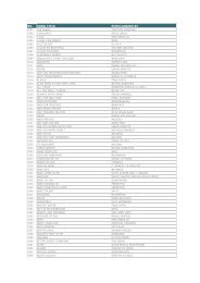
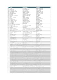
CH6<strong>LED</strong>selectgroup5 150—16 GobogroupA17—33 GobogroupB35—50 GobogroupC51—67 GobogroupD68—84 GobogroupE85—101 GobogroupF102—11 Gobo8 groupG119—135136—152153—169170—186187—203204—220221—237GobogroupHGobogroupIGobogroupJGobogroupKGobogroupLGobogroupMGobogroupNStatic gobo groupStatic gobo groupStatic gobo groupStatic gobo groupStatic gobo group(3group<strong>LED</strong> output differentgobo)Lock position static gobogroupLock position static gobogroupMove gobo groupMove gobo groupMove gobo groupMove gobo groupMove gobo groupMove gobo groupGradient move gobogroup238—25 Gobo Gradient move goboAdjust CH4to changegradient speed( fast—slow ); whenCH5 is 255 too,can show11
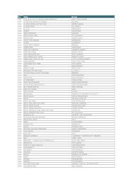
CH7CH8CH9CH10CH115 groupOgroupall the goboMovementspeed0—255 slow——fast(0 no effective,stop movement)Lightgroup 0—255 Brightness——dark1dimmerLightGradient, the dimmer is nogroup 0—255 Brightness——darkeffective2dimmerLightgroup 0—255 Brightness——dark3dimmerOFF 0 —22Auto move mode/soundcontrol mode offCH1——CH10 effective23 —45 Auto move mode 146 —68 Auto move mode 2Program69 —91 Auto move mode 3CH1——CH10 control noauto92 Auto move mode 4effectiverunning—114mode115—13 Auto move mode 57 [Collection1—4 mode]138—16 Sound control mode 1 [sound0 control auto running]161—18 Sound control mode 2 [flash3 sound control mode]Sound184—20 Sound control mode 3control6mode207—22 Sound control mode 49230—25 Sound control mode 55Ⅶ、Maintenance1. Clean and use frequencyTo confirm the power supply have cut off before disconnect the light or repair it ,it is veryimportant to keep the light cleaning .not only can keep the light maximum brightness output butalso can prolong their use life . please use the high quality professional glass and soft cloth toclear up the equipment ,not permission to use the alcohol and organic liquid clean at least onceeach year use vacuum dust collector .When the light does not start, check whether the light power supply fuse12
lown or not, if blow, install the appropriate fuse, and start the light after findout troubleshooting, but please attention to the technically person allowed tocarry out maintenance work.2. Products returnedIf it is the products quality problem, the customer can be based on the actualsituation, to decide whether need the product parts to replace.3. Complain( 1) The salesman will check the details of complained problem, included theitem no、 delivered quantity、 delivery time、 faulty and pictures, and therequirement of customer( 2) The customer service technicians to analyze and contact with customers byphone, to guide customer.(3) Quality Technology Department analysis of customer complaints and give apreliminary identified. The units must be offer analysis and treatmentmeasures on time.Ⅷ、Faulty DisposalFamiliar FaultyLight can not startLight can be shine well, but cannot be control by controllerSome of <strong>LED</strong> not brightnessDisposal1.Check if the fuse burnt out or not2.Check if the power connect well or not3.Check if the circuit board +12V or +5V short circuit ofearth1.Check if the light’s DMX original address setup right ornot. Check the connection details of communicationcontrol wire1、Check if <strong>LED</strong> lamp damage or not13