
You also want an ePaper? Increase the reach of your titles
YUMPU automatically turns print PDFs into web optimized ePapers that Google loves.
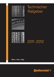
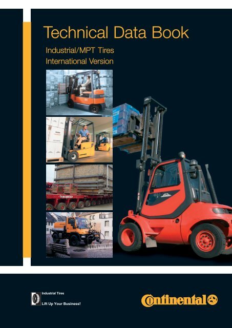
Technical Data Book<br />
Indus<strong>tr</strong>ial/MPT Tires<br />
International Version
3<br />
Inhaltsverzeichnis<br />
Published by<br />
© 2007 by Contin<strong>en</strong>tal Akti<strong>en</strong>gesellschaft Hannover.<br />
All rights reserved.<br />
The cont<strong>en</strong>ts of this publication are the result of many years of research and experi<strong>en</strong>ce<br />
gained in application technology. All information is giv<strong>en</strong> in good faith; it does not repres<strong>en</strong>t<br />
a guarantee with respect to characteristics and does not exempt the user from testing the<br />
suitability of products including checking with respect to indus<strong>tr</strong>ial property rights of any third<br />
parties. No liability whatsoever will be accepted for damage, regardless of its nature and its<br />
legal basis, arising from advice giv<strong>en</strong> in this publication. Products are subject to technical<br />
changes as a result of new developm<strong>en</strong>ts.<br />
Photo Mammoet Transport front page by “LVZ.G.Hunger”<br />
Contin<strong>en</strong>tal´s range of publications in this series:<br />
Technical Data Book: Pass<strong>en</strong>ger Car Tires<br />
Technical Data Book: Commercial Vehicle Tires<br />
Edition 06/2008<br />
Previous Edition 05/2007
Cont<strong>en</strong>ts<br />
In<strong>tr</strong>oduction<br />
Units of measurem<strong>en</strong>t and definitions . . . . . . . . . . . . . . . . . . . . . . . . . . . . . . . . . . . . . 6<br />
Tire designations . . . . . . . . . . . . . . . . . . . . . . . . . . . . . . . . . . . . . . . . . . . . . . . . . . . . . 7<br />
Pneumatic Tires<br />
Operating ins<strong>tr</strong>uctions . . . . . . . . . . . . . . . . . . . . . . . . . . . . . . . . . . . . . . . . . . . . . . . . 10<br />
New – Tubeless Sealing Ring - TSR . . . . . . . . . . . . . . . . . . . . . . . . . . . . . . . . . . . . . . 11<br />
Radial Tires . . . . . . . . . . . . . . . . . . . . . . . . . . . . . . . . . . . . . . . . . . . . . . . . . . . . . . . . 14<br />
Size range, specifications and tire load capacities . . . . . . . . . . . . . . . . . . . . . . . . . . . 18<br />
Crossply Tires . . . . . . . . . . . . . . . . . . . . . . . . . . . . . . . . . . . . . . . . . . . . . . . . . . . . . . 22<br />
Size range, specifications and tire load capacities . . . . . . . . . . . . . . . . . . . . . . . . . . 24<br />
SE-Tires<br />
Contin<strong>en</strong>tal Super Elastic Tires. . . . . . . . . . . . . . . . . . . . . . . . . . . . . . . . . . . . . . . . . . 28<br />
Tire cons<strong>tr</strong>uction. . . . . . . . . . . . . . . . . . . . . . . . . . . . . . . . . . . . . . . . . . . . . . . . . . . . . 29<br />
New – Innovation CSEasy . . . . . . . . . . . . . . . . . . . . . . . . . . . . . . . . . . . . . . . . . . . . . 30<br />
SC 18 . . . . . . . . . . . . . . . . . . . . . . . . . . . . . . . . . . . . . . . . . . . . . . . . . . . . . . . . . . . . . 32<br />
New – SC20 . . . . . . . . . . . . . . . . . . . . . . . . . . . . . . . . . . . . . . . . . . . . . . . . . . . . . . . . 34<br />
Super Elastic solid tires . . . . . . . . . . . . . . . . . . . . . . . . . . . . . . . . . . . . . . . . . . . . . . . 36<br />
Contin<strong>en</strong>tal Super Clean . . . . . . . . . . . . . . . . . . . . . . . . . . . . . . . . . . . . . . . . . . . . . . 37<br />
Size range, specifications and tire load capacities . . . . . . . . . . . . . . . . . . . . . . . . . . 38<br />
Press-on Bands<br />
Contin<strong>en</strong>tal Press-on Bands . . . . . . . . . . . . . . . . . . . . . . . . . . . . . . . . . . . . . . . . . . . 44<br />
Rim versions . . . . . . . . . . . . . . . . . . . . . . . . . . . . . . . . . . . . . . . . . . . . . . . . . . . . . . . 45<br />
Tread layer designs . . . . . . . . . . . . . . . . . . . . . . . . . . . . . . . . . . . . . . . . . . . . . . . . . . 45<br />
Steel banded press-on bands . . . . . . . . . . . . . . . . . . . . . . . . . . . . . . . . . . . . . . . . . . 46<br />
Press-on bands with steel wire reinforcem<strong>en</strong>t . . . . . . . . . . . . . . . . . . . . . . . . . . . . . . 48<br />
Multi Purpose Tires<br />
MPT-Radial . . . . . . . . . . . . . . . . . . . . . . . . . . . . . . . . . . . . . . . . . . . . . . . . . . . . . . . . 50<br />
MPT-Crossply . . . . . . . . . . . . . . . . . . . . . . . . . . . . . . . . . . . . . . . . . . . . . . . . . . . . . . 52<br />
MPT-Operating regulations . . . . . . . . . . . . . . . . . . . . . . . . . . . . . . . . . . . . . . . . . . . . 54<br />
Load capacities for various maximum design speeds and for special applications . . 55<br />
Technical data and load capacities – MPT Radial Tires . . . . . . . . . . . . . . . . . . . . . . . 56<br />
Recomm<strong>en</strong>ded tire pressures for tires on off-road vehicles . . . . . . . . . . . . . . . . . . . . 58<br />
Recomm<strong>en</strong>ded load capacities for use on wheel loaders . . . . . . . . . . . . . . . . . . . . . 59<br />
Technical data and load capacities – MPT Crossply Tires . . . . . . . . . . . . . . . . . . . . . 60<br />
Size range, specifications and tire load capacities . . . . . . . . . . . . . . . . . . . . . . . . . . 62<br />
3
4<br />
Inhaltsverzeichnis<br />
Rims and accessories<br />
Explanations and operating conditions for rims . . . . . . . . . . . . . . . . . . . . . . . . . . . . . 67<br />
Rims for indus<strong>tr</strong>ial vehicles . . . . . . . . . . . . . . . . . . . . . . . . . . . . . . . . . . . . . . . . . . . . 69<br />
Tapered base rims to DIN 7820 requirem<strong>en</strong>ts for commercial vehicles<br />
and indus<strong>tr</strong>ial <strong>tr</strong>ucks . . . . . . . . . . . . . . . . . . . . . . . . . . . . . . . . . . . . . . . . . . . . . . . . . 70<br />
Semi drop c<strong>en</strong><strong>tr</strong>e rims for commercial, all-purpose and earth-moving vehicles . . . . . 71<br />
Rims for earth-moving equipm<strong>en</strong>t . . . . . . . . . . . . . . . . . . . . . . . . . . . . . . . . . . . . . . . 72<br />
Well-base rims for light commercial and agricultural vehicles . . . . . . . . . . . . . . . . . . 73<br />
Well-base rims for light commercial vehicles symme<strong>tr</strong>ical<br />
and asymme<strong>tr</strong>ical versions . . . . . . . . . . . . . . . . . . . . . . . . . . . . . . . . . . . . . . . . . . . . 74<br />
Drop c<strong>en</strong><strong>tr</strong>e rims for Implem<strong>en</strong>t-, MPT- and Sand tires. . . . . . . . . . . . . . . . . . . . . . . . 75<br />
Recomm<strong>en</strong>ded minimum dual spacing for twin tires . . . . . . . . . . . . . . . . . . . . . . . . . 76<br />
Rims for press-on bands . . . . . . . . . . . . . . . . . . . . . . . . . . . . . . . . . . . . . . . . . . . . . . 78<br />
Rims for press-on bands (me<strong>tr</strong>ic sizes) with cylindrical or tapered base design . . . . 80<br />
Rims for press-on bands (inch sizes) with cylindrical or tapered base design . . . . . . 82<br />
Rims for press-on bands (me<strong>tr</strong>ic sizes) with cylindrical or tapered base design . . . . 82<br />
Valve accessorie . . . . . . . . . . . . . . . . . . . . . . . . . . . . . . . . . . . . . . . . . . . . . . . . . . . . . 84<br />
Valves for tubes . . . . . . . . . . . . . . . . . . . . . . . . . . . . . . . . . . . . . . . . . . . . . . . . . . . . . 85<br />
Rubber valves for tubeless fitting . . . . . . . . . . . . . . . . . . . . . . . . . . . . . . . . . . . . . . . 85<br />
Screw-on angled valves with turning plate . . . . . . . . . . . . . . . . . . . . . . . . . . . . . . . . 86<br />
Maint<strong>en</strong>ance and care<br />
Regrooving of CSE-tires . . . . . . . . . . . . . . . . . . . . . . . . . . . . . . . . . . . . . . . . . . . . . . 87<br />
Fittting and removal<br />
Fitting and removal of CSE tires . . . . . . . . . . . . . . . . . . . . . . . . . . . . . . . . . . . . . . . . 89<br />
Fitting and removal using an SE Unimount . . . . . . . . . . . . . . . . . . . . . . . . . . . . . . . . 90<br />
Fitting and removal using a 4-claw press . . . . . . . . . . . . . . . . . . . . . . . . . . . . . . . . . . 91<br />
Fitting and removal using a plate press . . . . . . . . . . . . . . . . . . . . . . . . . . . . . . . . . . . 92<br />
Additional tools to further facilitate tire fitting using a 4-claw or plate press. . . . . . . . 94<br />
Set of removal rings . . . . . . . . . . . . . . . . . . . . . . . . . . . . . . . . . . . . . . . . . . . . . . . . . . 95<br />
Fitting and removal of CSEasy . . . . . . . . . . . . . . . . . . . . . . . . . . . . . . . . . . . . . . . . . . 96<br />
Fitting and removal of CSE tires with SIT® type base . . . . . . . . . . . . . . . . . . . . . . . . 98<br />
Fitting and removal of press-on bands with cylindrical base . . . . . . . . . . . . . . . . . 100<br />
Contin<strong>en</strong>tal press-on bands – Fitting ins<strong>tr</strong>uction for tapered base type . . . . . . . . . . 104<br />
Service . . . . . . . . . . . . . . . . . . . . . . . . . . . . . . . . . . . . . . . . . . . . . . . . . . . . . . . . . . 107
On the following pages we have compiled compreh<strong>en</strong>sive technical data and related<br />
information regarding tires and accessories with the greatest care and as completely as<br />
possible according to the pres<strong>en</strong>t status in developm<strong>en</strong>t.<br />
If particularly important decisions are to be made on the basis of information giv<strong>en</strong> in<br />
this guide, further data covering relevant standards such as ETRTO*) and DIN, plus the<br />
WdK**) Guidelines can also be consulted. Additionally, special information can of course<br />
always be obtained from us at the following address:<br />
Contin<strong>en</strong>tal AG<br />
P.O. Box 169<br />
D-30001 Hanover (Germany<br />
The data giv<strong>en</strong> in this guide is based on average operating conditions as are normally<br />
found in C<strong>en</strong><strong>tr</strong>al Europe.<br />
For operating conditions which differ from these, please contact us.<br />
The tires sizes giv<strong>en</strong> here are not always id<strong>en</strong>tical to the ones available in the size range.<br />
In this guide tires which have be<strong>en</strong> specially developed for indus<strong>tr</strong>ial vehicles are referred<br />
to as Indus<strong>tr</strong>ial tires.<br />
Warning<br />
The following ins<strong>tr</strong>uctions must be observed if vehicle safety is to be guaranteed.<br />
This applies above all to ins<strong>tr</strong>uctions regarding tire pressure. Failure to comply with<br />
these ins<strong>tr</strong>uctions could result in tire damage that may lead to tire failure under certain<br />
circumstances. And blow-outs can cause <strong>tr</strong>affic accid<strong>en</strong>ts involving damage to<br />
property and/or personal injury.<br />
*) ETRTO = THE EUROPEAN TIRE<br />
AND RIM TECHNICAL ORGANISATION, BRÜSSELS<br />
**) WdK = Wirtschaftsverband der<br />
deutsch<strong>en</strong> Kautschukindus<strong>tr</strong>ie e.V., Frankfurt.<br />
(Association of the German Rubber Indus<strong>tr</strong>y, Frankfurt)<br />
5
6<br />
In<strong>tr</strong>oduction<br />
Units of measurem<strong>en</strong>t and definitions (DIN 70020)<br />
The technical specifications giv<strong>en</strong> in the tables g<strong>en</strong>erally comply with <strong>international</strong><br />
ETRTO and DIN standards.<br />
Additional information, such as further tire sizes or versions, together with the static<br />
radius, is provided in compliance with DIN or with WdK-Guidelines.<br />
L<strong>en</strong>gths<br />
are giv<strong>en</strong> in millime<strong>tr</strong>es (mm).<br />
Tire pressure in “bar”<br />
(Tire inflation) is giv<strong>en</strong> as an overpressure in bar and refers to the cold tire.<br />
Tire pressure in “kPa”<br />
(Tire inflation).<br />
Max. outer diameter of tire in service<br />
is the maximum diameter permitted in the <strong>tr</strong>ead c<strong>en</strong><strong>tr</strong>e as a result of perman<strong>en</strong>t growth<br />
during tire use.<br />
Max. operational width<br />
is the maximum permitted width. It includes scuff ribs, decorative ribs, tire markings,<br />
and perman<strong>en</strong>t growth during use.<br />
Static radius<br />
is the distance from the stationary tire c<strong>en</strong><strong>tr</strong>e level to the ground.<br />
Actual value<br />
is the actual measurem<strong>en</strong>t of a Contin<strong>en</strong>tal tire.<br />
The rolling circumfer<strong>en</strong>ce<br />
is the road distance covered by a point on the <strong>tr</strong>ead during a single rotation of the<br />
wheel.<br />
Con<strong>tr</strong>ol of measurem<strong>en</strong>ts<br />
on the fitted and inflated tire with calibration tire pressure according to DIN 70020,<br />
Sheet 5.<br />
Loadcapacities<br />
are giv<strong>en</strong> in kgs (weight in the s<strong>en</strong>se of a mass).<br />
CSE tires<br />
should always be interchangeable with pneumatic tires.<br />
The maximum measurem<strong>en</strong>ts are, therefore to be tak<strong>en</strong> wh<strong>en</strong> designing the fitting clearance.<br />
The effective outer diameter of CSE tires is approx. 2% smaller than that of pneumatic<br />
tires. However, since the degree of deflection is less, the static radius r stat. is approximately<br />
the same. Vehicle designers should bear in mind the maximum values for tire outer<br />
diameter and width wh<strong>en</strong> planning the wheel space of a vehicle, if standard approved<br />
tires are to fit without any res<strong>tr</strong>ictions. Should this by way of exception not be possible<br />
the safety risk.
Tire designations<br />
EIn the course of developm<strong>en</strong>t a variety of designations for pneumatic tires of vehicles<br />
have be<strong>en</strong> in<strong>tr</strong>oduced. Ev<strong>en</strong> today various designations are in concurr<strong>en</strong>t use.<br />
CSE-tires bear the same designation as pneumatic cross-ply tires, with the added indication<br />
of the rim width.<br />
Also, the word “SOLID” can be added to the size designation.<br />
The table below gives a summary of the tire designations<br />
and their meaning:<br />
Tiregroup<br />
Pneumatic<br />
tires<br />
Designation example Example contains ref. for<br />
Tire-1) size<br />
7.00-12<br />
7.00 R 12<br />
23x5<br />
18x7–8<br />
18x7 R 8<br />
180/70 R 8<br />
250-15<br />
355/65-15<br />
PR-2) value<br />
14<br />
16<br />
6<br />
14<br />
16<br />
16<br />
18<br />
24<br />
Operat-3) code<br />
-<br />
136 A5<br />
-<br />
-<br />
-<br />
125 A 5<br />
125 A 5<br />
-<br />
Outer dia<br />
A<br />
-<br />
-<br />
23''<br />
18''<br />
18''<br />
-<br />
-<br />
-<br />
Tire width<br />
B<br />
7''<br />
7''<br />
5''<br />
7''<br />
7''<br />
180 mm<br />
250 mm<br />
355 mm<br />
H:B<br />
%<br />
-<br />
-<br />
-<br />
-<br />
-<br />
70<br />
-<br />
65<br />
Rim dia.<br />
d<br />
12''<br />
12''<br />
-<br />
8''<br />
8''<br />
8''<br />
15''<br />
15''<br />
CSE tires 18x7-8/4.33 SOLID 125 A 18'' 7'' – 8'' 4.33<br />
Press-on<br />
bands<br />
200/75-100<br />
16x6x10 1 ⁄2<br />
1) “–” = cross-ply design; R = radial design<br />
2) PR = load capacity category<br />
3) Operational code = Load Index (LI) and Speed Symbol (SSY)<br />
-<br />
-<br />
-<br />
-<br />
200 mm<br />
16''<br />
75 mm<br />
6''<br />
-<br />
-<br />
100mm<br />
10 1 ⁄2''<br />
Rim width<br />
b<br />
-<br />
-<br />
-<br />
-<br />
-<br />
-<br />
-<br />
-<br />
-<br />
-<br />
7
8<br />
In<strong>tr</strong>oduction<br />
Pneumatic tires CSE-tires<br />
SSY<br />
Refer<strong>en</strong>ce-<br />
speed<br />
km/h mph<br />
A 1 5 3<br />
A 2 10 6<br />
A 3 15 9<br />
A 4 20 12<br />
A 5 25 16<br />
A 6 30 19<br />
A 7 35 22<br />
A 8 40 25<br />
B 50 31<br />
C 60 37<br />
D 65 40<br />
E 70 44<br />
F 80 50<br />
G 90 56<br />
J 100 62<br />
K 110 68<br />
L 120 75<br />
M 130 81<br />
N 140 87<br />
P 150 93<br />
AØ = tire outer dia.<br />
AØmax. = max. outer diameter of tire in<br />
service<br />
B = cross-sectional width<br />
Bmax. = maximum operational width<br />
H = tire height<br />
dØ = rim diameter<br />
b = rim width<br />
f = deflection under load<br />
rstat. = static radius<br />
H:B = aspect ratio<br />
In the past the tire load capacity category was indicated<br />
only by a PR value.<br />
For indus<strong>tr</strong>ial radial, MPT and <strong>tr</strong>uck tires there is an increasing<br />
use of a number-letter code for accurate tire designation.<br />
The load capacity is giv<strong>en</strong> as a Load Index (LI) – see the<br />
table on next page – for the relevant refer<strong>en</strong>ce speed.<br />
The refer<strong>en</strong>ce speed is indicated in the form of a Speed<br />
Symbol (SSY) – see table (left).
Load-Indices (LI)<br />
LI kg<br />
19 77,5<br />
20 80<br />
21 82,5<br />
22 85<br />
23 87,5<br />
24 90<br />
25 92,5<br />
26 95<br />
27 97,5<br />
28 100<br />
29 103<br />
30 106<br />
31 109<br />
32 112<br />
33 115<br />
34 118<br />
35 121<br />
36 125<br />
37 128<br />
38 132<br />
39 136<br />
40 140<br />
41 145<br />
42 150<br />
43 155<br />
44 160<br />
45 165<br />
46 170<br />
47 175<br />
48 180<br />
49 185<br />
50 190<br />
51 195<br />
52 200<br />
53 206<br />
54 212<br />
55 218<br />
56 224<br />
57 230<br />
58 236<br />
LI kg<br />
59 243<br />
60 250<br />
61 257<br />
62 265<br />
63 272<br />
64 280<br />
65 290<br />
66 300<br />
67 307<br />
68 315<br />
69 325<br />
70 335<br />
71 345<br />
72 355<br />
73 365<br />
74 375<br />
75 387<br />
76 400<br />
77 412<br />
78 425<br />
79 437<br />
80 450<br />
81 462<br />
82 475<br />
83 487<br />
84 500<br />
85 515<br />
86 530<br />
87 545<br />
88 560<br />
89 580<br />
90 600<br />
91 615<br />
92 630<br />
93 650<br />
94 670<br />
95 690<br />
96 710<br />
97 730<br />
98 750<br />
LI kg<br />
99 775<br />
100 800<br />
101 825<br />
102 850<br />
103 875<br />
104 900<br />
105 925<br />
106 950<br />
107 975<br />
108 1000<br />
109 1030<br />
110 1060<br />
111 1090<br />
112 1120<br />
113 1150<br />
114 1180<br />
115 1215<br />
116 1250<br />
117 1285<br />
118 1320<br />
119 1360<br />
120 1400<br />
121 1450<br />
122 1500<br />
123 1550<br />
124 1600<br />
125 1650<br />
126 1700<br />
127 1750<br />
128 1800<br />
129 1850<br />
130 1900<br />
131 1950<br />
132 2000<br />
133 2060<br />
134 2120<br />
135 2180<br />
136 2240<br />
137 2300<br />
138 2360<br />
LI kg<br />
139 2430<br />
140 2500<br />
141 2575<br />
142 2650<br />
143 2725<br />
144 2800<br />
145 2900<br />
146 3000<br />
147 3075<br />
148 3150<br />
149 3250<br />
150 3350<br />
151 3450<br />
152 3550<br />
153 3650<br />
154 3750<br />
155 3875<br />
156 4000<br />
157 4125<br />
158 4250<br />
159 4375<br />
160 4500<br />
161 4625<br />
162 4750<br />
163 4875<br />
164 5000<br />
165 5150<br />
166 5300<br />
167 5450<br />
168 5600<br />
169 5800<br />
170 6000<br />
171 6150<br />
172 6300<br />
173 6500<br />
174 6700<br />
175 6900<br />
176 7100<br />
177 7300<br />
178 7500<br />
LI kg<br />
179 7750<br />
180 8000<br />
181 8250<br />
182 8500<br />
183 8750<br />
184 9000<br />
185 9250<br />
186 9500<br />
187 9750<br />
188 10000<br />
189 10300<br />
190 10600<br />
191 10900<br />
192 11200<br />
193 11500<br />
194 11800<br />
195 12150<br />
196 12500<br />
197 12850<br />
198 13200<br />
199 13600<br />
200 14000<br />
201 14500<br />
202 15000<br />
203 15500<br />
204 16000<br />
205 16500<br />
206 17000<br />
207 17500<br />
208 18000<br />
209 18500<br />
210 19000<br />
211 19500<br />
212 20000<br />
9
10<br />
Operating ins<strong>tr</strong>uctions<br />
DIN 7811, WdK-Guideline 211,<br />
WdK-Guideline 153, ETRTO<br />
Load capacity. Wh<strong>en</strong> determining the minimum tire size necessary for any particular<br />
wheel position of a vehicle, the approved load and the maximum design speed of the<br />
vehicle must always be used as a basis.<br />
Tire pressure. The tire pressures giv<strong>en</strong> in the tables are minimum tire pressures and<br />
should be used only as a guide.<br />
For special operating conditions specific tire pressures can be recomm<strong>en</strong>ded.<br />
All tire pressures refer to the “cold” tire which has be<strong>en</strong> standing outdoors for several<br />
hours, not exposed to int<strong>en</strong>se sunlight.<br />
Rims. Only the rims indicated are approved for equipping new vehicle series. In the following<br />
tables the recomm<strong>en</strong>ded rim is printed in bold type.<br />
Wheels. The load capacity must be adequate in all cases.
New<br />
Tubeless Sealing Ring – TSR<br />
Greater safety and mobility<br />
The TSR <strong>en</strong>ables tubeless indus<strong>tr</strong>ial tires<br />
to be fitted on to standard indus<strong>tr</strong>ial tire<br />
rims that, because of their design, would<br />
normally require an inner tube and bead<br />
flap. The TSR consists of a rubber ring<br />
with an integrated tire valve. This rubber<br />
ring fits on the cylindrical part of the rim<br />
betwe<strong>en</strong> the two tire beads and provides<br />
an airtight seal for the air chamber without<br />
the need for an inner tube and bead flap.<br />
Drawbacks of tube type tires<br />
· Rapid pressure loss in the case of tire failure<br />
· Risk of damage to freight and vehicle<br />
· Vehicle is immediately out of action and work is<br />
interrupted<br />
· Risk of valve being torn out<br />
Advantages of tubeless tires<br />
· No sudd<strong>en</strong> pressure loss in the case of tire failure<br />
The vehicle remains operational and can still<br />
be driv<strong>en</strong><br />
There are no sudd<strong>en</strong> load shifts, which means<br />
greater vehicle stability<br />
· If the tire turns on the rim, this is not critical<br />
· Low aspect ratio tires are more durable<br />
· Faster, easier tire fitting<br />
· No need for a cover under the valve hole to prev<strong>en</strong>t<br />
the bead flap from being forced out<br />
· Fewer compon<strong>en</strong>ts than with tube type tires<br />
11
12<br />
Luf<strong>tr</strong>eif<strong>en</strong> Pneumatic tires<br />
5/2007<br />
qui est le seul valable.<br />
Nach Drucklegung hat sich herausgestellt,<br />
Español<br />
dass die Tabelle auf Seite 12 ein<strong>en</strong> Fehler<br />
Hoja adjunta para Nociones Técnicas<br />
aufweist. Daher hat nur die unt<strong>en</strong> aufgeführte<br />
Neumáticos Indus<strong>tr</strong>iales / MPT / EM, Edición<br />
Tabelle Gültigkeit.<br />
5/2007<br />
English<br />
Después de realizada la impresión se ha des-<br />
Insert for the Technical Data Book<br />
cubierto que la tabla de la página 12 pres<strong>en</strong>ta<br />
Wichtige Indus<strong>tr</strong>ial, Important Hinweise Multi note Purpose, Earth Mover Tires, un error. Por ello sólo ti<strong>en</strong>e validez la tabla<br />
Edition 5/2007<br />
indicada abajo.<br />
Der TSRs TSR may darf only nur be in used Contin<strong>en</strong>tal with those Indus<strong>tr</strong>iereif<strong>en</strong> Contin<strong>en</strong>tal verw<strong>en</strong>det indus<strong>tr</strong>ial tires werd<strong>en</strong>, designed die für to die accommoVerw<strong>en</strong>- After printing the Technical Data Book an<br />
dung Italiano<br />
error<br />
date them.<br />
was<br />
mit dem<br />
detected<br />
Such TSR tires<br />
in<br />
geeignet<br />
the<br />
carry<br />
table<br />
the sind.<br />
on<br />
following<br />
page<br />
Der Hinweis<br />
12.<br />
refer<strong>en</strong>ce „This on tyre the sidewall: is compatible "This with tire is the compatContin<strong>en</strong>tal Inserto per la guida tecnica pneumatici<br />
Please ible with TSR only the system“ use Contin<strong>en</strong>tal the corrected steht TSR auf table system". der Reif<strong>en</strong>seit<strong>en</strong>wand.<br />
below.<br />
Indus<strong>tr</strong>ia / MPT / EM, edizione 5/2007<br />
Reif<strong>en</strong> Tires carrying mit dem the Hinweis, refer<strong>en</strong>ce dass that sie they TSR-tauglich are compatible sind, with könn<strong>en</strong> TSRs auch can mit also Schlauch be used with und<br />
Wulstband Français an inner tube eingesetzt and bead werd<strong>en</strong>. flap.<br />
Dopo la stampa è stato accertato un errore<br />
Feuille d'insertion pour le manuel technique nella tabella a pagina 12, chevi<strong>en</strong>e quindi<br />
Das<br />
Pneus<br />
The TSR TSR-System<br />
indus<strong>tr</strong>iels<br />
system is<br />
/<br />
ist<br />
MPT<br />
not nicht suitable<br />
/ génie<br />
für mitt<strong>en</strong>geteilte<br />
civil,<br />
for c<strong>en</strong><strong>tr</strong>e-split Felg<strong>en</strong> rims.<br />
sostituita<br />
geeignet.<br />
con quella sotto riportata.<br />
édition 5/2007<br />
Reif<strong>en</strong>größe<br />
Tire size<br />
Dim<strong>en</strong>sion de pneu<br />
Tamaño neumático<br />
Misura del pneum.<br />
Felge<br />
Rim<br />
Jante<br />
Llanta<br />
Cerchio<br />
TSR-Artikelbezeichnung<br />
TSR item designation<br />
Désignation d'article du<br />
TSR<br />
D<strong>en</strong>ominación TSR<br />
Sigla TSR<br />
125/75R8 5.00R8 125/75R8 3.00 3.00 D-8 TSR TSR 3.00/3.25TL8 3.00TL8 TL COTL TL CO<br />
0793017<br />
125/75R8<br />
5.00R8 150/75R8<br />
150/75R8 180/70R8 150/75R8<br />
180/70R8 6.00R9 180/70R8<br />
3.00 D-8 3.25 I 8<br />
3.00 D-8 3.25 I 8 4.33 R-8<br />
4.33 R-8 4.33 4.00 4.33 R-8 E-9<br />
TSR 3.00/3.25TL8 TL CO<br />
TSR 3.00/3.25TL8 TL CO<br />
TSR 4.33TL8 TL CO<br />
TSR 4.33TL8 TL CO<br />
TSR TSR 4.33TL8 4.00TL9 TL CO<br />
0793002<br />
0793002<br />
0793003<br />
0793003<br />
0793004<br />
6.50R10<br />
6.00R9 225/75R10<br />
5.00 F-10<br />
4.00 E-9 6.50 F-10<br />
5.50 F-10 TSR 5.00/5.50TL10 TL CO<br />
TSR 4.00TL9 TL CO TSR 6.50TL10 TL CO<br />
0793005<br />
0793004<br />
0793007<br />
6.50R10 7.00R12 6.50R10 5.00 5.00 F-10 S-12 5.50 F-10 TSR TSR 5.00/5.50TL10 5.00TL12 TL COTL TL CO 0793005 0793001 0793005<br />
225/75R10 250/75R12 225/75R10 6.50 8.00 6.50 F-10 G-12 TSR TSR 6.50TL10 8.00TL12 TL CO 0793007 0793011 0793007<br />
7.00R15<br />
7.00R12 7.50R15<br />
5.5-15<br />
5.50 S-120 6.0-15 6.5-15<br />
TSR 5.50TL15 TL CO<br />
TSR 5.00TL12 TL CO TSR 6.00/6.50TL15 CO<br />
0793006<br />
0793001<br />
0793008<br />
250/75R12 8.25R15 250/75R12 8.0 6.5-15 8.0 G-12 TSR TSR 8.00TL12 6.50TL15 TL CO CO 0793011 0793000 0793011<br />
7.00R15 225/75R15 7.00R15 5.5-15 7.0-15 5.5-15 TSR TSR 5.50TL15 7.00TL15 TL CO CO 0793006 0793009 0793006<br />
250/70R15<br />
7.50R15 315/70R15<br />
7.0-15 7.5-15<br />
6.0-15/6.5-15 8.0-15<br />
TSR 7.00/7.50TL15 CO<br />
TSR 6.00/6.50TL15 CO 7.50R15 TSR 8.00TL15 TL CO<br />
0793015<br />
0793008<br />
0793012<br />
8.25R15 355/65R15 8.25R15 6.5-15 9.75-15 6.5-15 TSR TSR 6.50TL15 9.75TL15 CO TL CO 8.25R15 0793000 0793014 0793000<br />
225/75R15 10.00R20 225/75R15 7.0-15 7.5-R20 7.0-15 TSR TSR 7.00TL15 7.50TL20 CO TL CO 225/75R15 0793009 0793010 0793009<br />
11.00R20<br />
250/70R15 12.00R20<br />
8.0-20<br />
7.0-15/7.5-15 8.0-20 8.5-20<br />
TSR 8.00TL20 CO<br />
TSR 7.00/7.50TL15 250/70R15 TSR 8.00/8.50TL20 CO<br />
0793013<br />
0793015<br />
0793016<br />
315/70R15 8.0-15 TSR 8.00TL15 TL CO 0793012<br />
TSR-Artikelnummer<br />
TSR item no.<br />
Référ<strong>en</strong>ce du TSR<br />
Número TSR<br />
Es Only sind new grundsätzlich TSRs (maximum nur neue, age 3 maximal years) should 3 Jahre ever alte be TSR used. zu verw<strong>en</strong>d<strong>en</strong>.<br />
D<strong>en</strong> The TSR must nur einmal only be verw<strong>en</strong>d<strong>en</strong>.<br />
used once.<br />
Reif<strong>en</strong>große 4Tire size Felge Rim TSR-Artikelbezeichnung TSR item designation TSR-Artikelnummer<br />
TSR item no.<br />
355/65R15 9.75-15 TSR 9.75TL15 TL CO 0793014<br />
10.00R20 7.5 R20 TSR 7.50TL20 TL CO 0793010<br />
11.00R20 8.0-20 TSR 8.00TL20 CO 11.00R20 0793013<br />
12.00R20 8.5-20 TSR 8.00/8.50TL20 12.00R20 0793016<br />
Codice articolo TSR
14<br />
Pneumatic tires<br />
Indus<strong>tr</strong>ial Pneumatic Tires<br />
G<strong>en</strong>eral Characteristics<br />
The cons<strong>tr</strong>uction of Indus<strong>tr</strong>ial Pneumatic Tires <strong>en</strong>sures excell<strong>en</strong>t ride comfort on unpaved<br />
ground ev<strong>en</strong> at high speeds. Also recomm<strong>en</strong>ded for use on public roads.<br />
Special applications by cons<strong>tr</strong>uction<br />
Radial: Crossply:<br />
· ex<strong>tr</strong>aordinary high mileage · <strong>en</strong>hanced stability<br />
· <strong>en</strong>hanced ride comfort (on paved grounds)<br />
· low rolling resistance · resistant to sidewall damage<br />
· very good <strong>tr</strong>action · good <strong>tr</strong>action<br />
· elec<strong>tr</strong>oconductive<br />
Suitable vehicles:<br />
· indoor service <strong>tr</strong>ailers · indus<strong>tr</strong>ial <strong>tr</strong>actors<br />
· forklift <strong>tr</strong>ucks · airport vehicles<br />
· heavy-duty <strong>tr</strong>ansport vehicles · self-powered lift vehicles<br />
· platform <strong>tr</strong>ucks · side-loading forklifts<br />
G<strong>en</strong>eral applications<br />
· logistics c<strong>en</strong><strong>tr</strong>es · airports<br />
· seaports · dockyards<br />
· indus<strong>tr</strong>y<br />
Core features Customer b<strong>en</strong>efits<br />
ConRad HT Radial - Indus<strong>tr</strong>ial Pneumatic Tires<br />
Tougher for longer service in heavy duty applications, with<br />
exclusive asymme<strong>tr</strong>ical half <strong>tr</strong>ack <strong>tr</strong>ead giving ex<strong>tr</strong>a b<strong>en</strong>efits<br />
in twin fitm<strong>en</strong>ts and steered wheels.<br />
• solid shoulder ➠ steady grip on twin fitm<strong>en</strong>ts<br />
and steering-wheels<br />
• ex<strong>tr</strong>a deep profile ➠ long service life for low operating<br />
costs<br />
• robust belted design ➠ reduced <strong>tr</strong>ead damage
New<br />
Core features Customer b<strong>en</strong>efits<br />
CONRAD Radial Indus<strong>tr</strong>ial Pneumatic<br />
Optimised <strong>tr</strong>ead pattern in 6 sizes<br />
7.00R12 ConRad<br />
165R13 ConRad<br />
8.25R15 ConRad<br />
250/70R15 ConRad<br />
315/70R15 ConRad<br />
12.00R20 ConRad<br />
• New <strong>tr</strong>ead pattern design ➠ Reduced driving noise<br />
with 3 circumfer<strong>en</strong>tial ribs ➠ Ev<strong>en</strong> wear pattern<br />
• Sturdy radial casing ➠ Optimum susp<strong>en</strong>sion and<br />
absorption<br />
➠ High durability and mileage<br />
15
16<br />
Radial Tires<br />
To achieve an optimum mile age, the following fitting recomm<strong>en</strong>dation<br />
should be observed:<br />
• For twin fitm<strong>en</strong>ts, the patterned <strong>tr</strong>ead sides should be turned towards each other.<br />
This avoids roof-shaped wear that can easily occur for twin tire fitm<strong>en</strong>ts.<br />
• For twin fitm<strong>en</strong>ts, tires should be fitted with the <strong>tr</strong>ead bars facing each other but<br />
arranged in offset positions.<br />
• Conical wear – which is frequ<strong>en</strong>tly observed on steering wheels – can be reduced by<br />
selective fitting, i.e. the smooth side should be fitted on the shoulder that is subject<br />
to more rapid wear.<br />
• Normally this will be the outer side of the vehicle. This fitting procedure has another<br />
advantage: the smooth outside shoulder means that <strong>tr</strong>ead blocks are not chunked off<br />
the shoulder if the tire hits an obstacle.
Core features Customer b<strong>en</strong>efits<br />
IC 80 Ex<strong>tr</strong>a Deep Radial - Indus<strong>tr</strong>ial Pneumatic Tires<br />
Greater damage resistance, designed for the toughest applications<br />
• ex<strong>tr</strong>a deep profile ➠ high mileage<br />
performance<br />
• robust belted cons<strong>tr</strong>uction ➠ reduces <strong>tr</strong>ead damage<br />
IC 70 Radial - Indus<strong>tr</strong>ial Pneumatic Tires<br />
The universal tire for all wheel positions.<br />
• good susp<strong>en</strong>sion ➠ excell<strong>en</strong>t ride comfort<br />
• ev<strong>en</strong> ground pressure ➠ good grip and <strong>tr</strong>action<br />
• robust belted cons<strong>tr</strong>uction ➠ reduces <strong>tr</strong>ead damage<br />
Tire design: All-steel cons<strong>tr</strong>uction<br />
Steel cord casing and reinforcing multiply steel cord belt. The<br />
flat <strong>tr</strong>ead shape means an ev<strong>en</strong> pressure dis<strong>tr</strong>ibution and thus<br />
ev<strong>en</strong> wear across the <strong>en</strong>tire <strong>tr</strong>ead width.<br />
Radial tires are conductive<br />
The leakage resistance of
18<br />
Radial tires<br />
Size range, specifications and<br />
tire load capacities ConRad HT<br />
Tire Rim Tube Flap Tire dim<strong>en</strong>sions<br />
and max. in service<br />
valve<br />
Size PR Code Standard value Actual value<br />
acc. o ETRTO<br />
width outer width outer dia.<br />
LI GSY dia. + 1% ± 1 %<br />
6.00 R 9 TL • 12 121 4.00 E-9<br />
6.00-9/21 x 8-9<br />
41.5 G 70/60 D<br />
100-9 165 551 160 541<br />
6.50 R 10 TL • 14 128 5.00 F-10 6.50/7.50-10<br />
41.5 G 70/60 D2) 130-10 182 600 176 591<br />
225/75 R 10 TL • 20 142<br />
23 x 9-10<br />
6.50 F-10<br />
225/75-10/60 D<br />
180-10 239 606 227 597<br />
7.00 R 12 TL • 16 136 5.00 S-12 7.00-12<br />
60 D/75 D<br />
130-12 198 685 194 677<br />
250/75 R 12 TL • 20 152<br />
27 x 10-12<br />
8.00 G 12<br />
250/75-12/60 D<br />
220-12 274 695 264 687<br />
165 R 13 TL • –<br />
102/<br />
A6<br />
4.50 x<br />
13B<br />
– – 174 606 167 599<br />
7.50 R 15 TL • 16 146<br />
6.0-15<br />
7.50-15<br />
8.25-15<br />
75 D/105 D<br />
170-15<br />
75 D-74<br />
5) 6.5-15 170-15<br />
218 787 211 776<br />
5) 223 787 216 776<br />
8.25R 15 TL • 18 153 6.5-15 170-155) 241 853 238 842<br />
225/75 R 15 TL<br />
(28 x 9 R 15)<br />
250/70 R 15 TL<br />
(250 R 15)<br />
315/70 R 15 TL<br />
(300 R 15)<br />
• 16 149 7.0-15<br />
28 x 9-15<br />
190-15<br />
250/70-15<br />
75 D-74<br />
95 D-74<br />
5) 245 732 221 728<br />
• 18 153<br />
7.0-15 190-155) 7.5-15 190-15<br />
264 745 240 743<br />
5) 269 745 245 743<br />
• 22 165 8.0-15<br />
300-15/<br />
355/65-15<br />
95 D-74/<br />
95 D-Z<br />
10.00-20<br />
127 D-Z<br />
11.00/12.00-20<br />
127 D-Z<br />
11.00/12.00-20<br />
127 D-Z<br />
240-15 5) 323 840 304 830<br />
355/65 R 15 TL • – 175 9.75-15 240-15 5) 372 861 332 835<br />
10.00 R 20 TL<br />
(290/95 R 20)<br />
11.00 R 20 TL<br />
(300/95 R 20)<br />
12.00 R 20 TL<br />
(330/95 R 20)<br />
ConRad HT<br />
CONRAD<br />
A 5 <strong>en</strong>tspricht 25 km/h<br />
• 18 166 7.5-20<br />
• 16 169 8.0-20<br />
• 20 176 8.5–20<br />
190-20 5) 309 1073 278 1064<br />
220-230 5) 309 1104 286 1100<br />
230-20 5) 338 1144 311 1140<br />
1) Static radius (actualvalue): A: for load capacity on other vehicles at 16 mph (25km/h), B: for load-wheel capacity on forklifts<br />
at 16 mph (25km/h).<br />
2) Use flap with c<strong>en</strong><strong>tr</strong>e valve hole.<br />
3) Other vehicles, e.g. platform <strong>tr</strong>ucks, <strong>tr</strong>ailers, <strong>tr</strong>actors, s<strong>tr</strong>addle carriers, forklifts without counterweight etc.
Static 1) Reif<strong>en</strong><strong>tr</strong>agfähigkeit<br />
radius<br />
Actual value Tire Pressure Stationary on other verhicles 3) on fork lifts Size<br />
± 2,5 % at max. speed (mph) max. 25 mph<br />
Steered<br />
A B bar kHa 6 16 25 Load wheel wheel 4)<br />
acc. to ETRTO<br />
251 246 10,0 1000 2190 1885 1450 1245 1885 1450 6.00 R 9 TL<br />
270 266 10,0 1000 2720 2340 1800 1605 2340 1800 6.50 R 10 TL<br />
268 262 10,0 1000 4005 3445 2650 2360 3445 2650 225/75 R 10 TL<br />
313 307 10,0 1000 3385 2915 2240 1995 2915 2240 7.00 R 12 TL<br />
309 300 10,0 1000 5365 4615 3550 3160 4615 3550 250/75 R 12 TL<br />
– – 4,5 450 – – 30 km/h 850 – – 165 R 13 TL<br />
360 353 10,0 1000 4530 3900 3000 2670 3900 3000<br />
– – 10,0 1000 4530 3900 3000 2670 3900 3000<br />
7.50 R 15 TL<br />
388 380 10,0 1000 5515 4745 3650 3250 4745 3650 8.25R 15 TL<br />
334 327 10,0 1000 4910 4225 3250 2895 4225 3250<br />
339 330 10,0 1000 5515 4745 3650 3250 4745 3650<br />
339 330 10,0 1000 5515 4745 3650 3250 4745 3650<br />
371 359 10,0 1000 7780 6695 5150 4585 6695 5150<br />
225/75 R 15 TL<br />
(28 x 9 R 15)<br />
250/70 R 15 TL<br />
(250 R 15)<br />
315/70 R 15 TL<br />
(300 R 15)<br />
365 347 10,0 1000 10420 8970 6900 – 8970 6900 355/65 R 15 TL<br />
492 448 10,0 1000 8000 6890 5300 4715 6890 5300<br />
507 497 10,0 1000 8760 7540 5800 5160 7540 5800<br />
522 513 10,0 1000 10720 9230 7100 6320 9230 7100<br />
10.00 R 20 TL<br />
(290/95 R 20)<br />
11.00 R 20 TL<br />
(300/95 R 20)<br />
12.00 R 20 TL<br />
(330/95 R 20)<br />
4) The steering wheel load capacities 16 mph (25km/h) are to be applied for tires on side-loading forklift <strong>tr</strong>ucks, s<strong>tr</strong>addle<br />
carriers and portal lift <strong>tr</strong>ucks speed of 16 mph (25km/h).<br />
5) The use of a valve shield is recomm<strong>en</strong>ded.<br />
The minimum dual spacing is indicated on page 76.<br />
• available<br />
19
20<br />
Radial tires<br />
Size range, specifications and<br />
tire load capacities<br />
Tire Rim Tube Flap Tire dim<strong>en</strong>sions<br />
and max. in service<br />
valve<br />
Size PR Code Standard value Actual value<br />
IC 70/IC 80<br />
IC IC width outer width outer dia.<br />
70 80 LI SSY dia. + 1% ± 1%<br />
acc. to ETRTO<br />
5.00 R 8 TL<br />
125/75 R 8 TL<br />
(15 x 4 1 ⁄2 R 8)<br />
150/75 R 8 TL<br />
(16 x 6 R 8)<br />
180/70 R 8 TL<br />
(18 x 7 R 8)<br />
•<br />
•<br />
10 111 3.00 D-8<br />
5.00-8<br />
41.5 G 70<br />
85-8 136 476 132 461<br />
4) 85-8 136 476 129 465<br />
• 12 100<br />
3.00 D-8<br />
31 ⁄4 I-8<br />
15 x 41 ⁄4-8/<br />
125/75-8<br />
43 D-60<br />
85–8<br />
85–8<br />
126<br />
129<br />
392<br />
392<br />
120<br />
124<br />
384<br />
384<br />
• 16 113<br />
16 x 6-8/<br />
115–8 160 439 150 425<br />
•<br />
•<br />
16 125<br />
4.33 R-8<br />
18 x 7-8<br />
41.5 G 70<br />
60 D<br />
115–8 182 465 171 452<br />
4) 115–8 182 465 168 465<br />
6.00 R 9 TL<br />
•<br />
•<br />
12 121 4.00 E-9<br />
6.00-9/ 21 x 8-9<br />
41.5 G 70/60 D<br />
100–9 165 551 160 529<br />
4) 100–9 165 551 161 551<br />
6.50 R 10 TL<br />
•<br />
•<br />
14 128<br />
5.00 F-10 6.50/7.50-10 130–10 182 600 180 577<br />
4) 5.50 F-10 41.5 G 70/60 D2) 130–10 187 600 176 586<br />
225/75 R 10 TL<br />
(23 x 9 R 10)<br />
• • 4) 20 142 6.50 F-10<br />
23 x 9-10/<br />
225/75-10/60 D<br />
180–10 239 606 228 587<br />
7.00 R 12 TL<br />
•<br />
16 136<br />
•<br />
5.00 S-12<br />
7.00-12<br />
60 D/75 D<br />
130–12 198 685 193 660<br />
4) 136 130–12 198 685 190 673<br />
250/75 R 12 TL<br />
(27 x 10 R 12)<br />
• 20 152 8.00 G-12<br />
27x10-12/<br />
250/75-12/60 D<br />
220–12 274 695 260 678<br />
7.00 R 15 TL • 14 140 5.5-15<br />
7.00-15/200-15<br />
75 D-74<br />
170-156) 203 761 197 737<br />
7.50 R 15 TL<br />
•<br />
16 146<br />
6.0-15 7.50-15/<br />
8.25-15<br />
170-15<br />
75 D/105 D/<br />
75 D-74<br />
6) •<br />
218 787 211 772<br />
4) 6.5-15 170-156) 224 787 207 773<br />
8.25 R 15 TL<br />
•<br />
18 153 6.5-15<br />
170-156) •<br />
241 853 237 826<br />
4) 170-156) 241 853 234 837<br />
225/75 R 15 TL<br />
(28 x 9 R 15)<br />
• 16 149 7.0-15 28 x 9-15/<br />
250/70-15<br />
75 D-74<br />
95 D-74<br />
190-156) 250/70 R 15 TL<br />
(250 R 15)<br />
•<br />
18 153<br />
7.0-15 190-15<br />
245 732 217 719<br />
6) •<br />
264 745 240 734<br />
4) 7.5-15 190-156) 269 745 245 755<br />
315/70 R 15 TL<br />
(300 R 15)<br />
A 5 = 25 km/h<br />
• 22 165 8.0-15<br />
300-15/355/65-15/<br />
95 D-74/95 D-Z<br />
240-15 6) 323 840 305 827<br />
1) Static radius (actualvalue): A: for load capacity on other vehicles at 16 mph (25km/h), B: for load-wheel capacity on forklifts<br />
at 16 mph (25km/h).<br />
2) Use flap with c<strong>en</strong><strong>tr</strong>e valve hole.<br />
3) Other vehicles, e.g. platform <strong>tr</strong>ucks, <strong>tr</strong>ailers, <strong>tr</strong>actors, s<strong>tr</strong>addle carriers, forklifts without counterweight etc.<br />
4) Maximum speed for IC 40 Ex<strong>tr</strong>a Deep <strong>tr</strong>ead pattern = 25 mph (40 km/h)
Static 1) Reif<strong>en</strong><strong>tr</strong>agfähigkeit<br />
radius<br />
Actual value Tire Pressure Stationary on other vehickles 3) on fork lifts Size<br />
± 2,5 % at max. speed (mph) max. 16 mph<br />
Load Steered<br />
A B bar kPa 6 16 25 5) 31 5) wheel 7) wheel 5)<br />
acc. to ETRTO<br />
209 204 10,0 1000 1650 1420 1090 975 920 1420 1090<br />
211 206 10,0 1000 1650 1420 1090 975 920 1420 1090<br />
174 170 10,0 1000 1210 1040 800 715 675 1040 800<br />
174 170 10,0 1000 1210 1040 800 715 675 1040 800<br />
194 189 10,0 1000 1740 1495 1150 1025 970 1495 1150<br />
200 194 10,0 1000 2495 2145 1650 1470 1390 2145 1650<br />
204 197 10,0 1000 2495 2145 1650 1470 1390 2145 1650<br />
242 236 10,0 1000 2190 1885 1450 1295 1220 1885 1450<br />
246 240 10,0 1000 2190 1885 1450 1295 1220 1885 1450<br />
260 253 10,0 1000 2720 2340 1800 1605 1515 2340 1800<br />
264 257 10,0 1000 2720 2340 1800 1605 1515 2340 1800<br />
256 246 10,0 1000 4005 3445 2650 2360 2230 3445 2650<br />
300 292 10,0 1000 3385 2915 2240 1995 1885 2915 2240<br />
307 299 10,0 1000 3385 2915 2240 1995 1885 2915 2240<br />
299 287 10,0 1000 5365 4615 3550 3160 – 4615 3550<br />
5.00 R 8 TL<br />
125/75 R 8 TL<br />
(15 x 41/2 R 8)<br />
150/75 R 8 TL<br />
(16 x 6 R 8)<br />
180/70 R 8 TL<br />
(18 x 7 R 8)<br />
6.00 R 9 TL<br />
6.50 R 10 TL<br />
225/75 R 10 TL<br />
(23 x 9 R 10)<br />
7.00 R 12 TL<br />
250/75 R 12 TL<br />
(27 x 10 R 12)<br />
338 331 10,0 1000 3775 3250 2500 2225 2100 3250 2500 7.00 R 15 TL<br />
348 340 10,0 1000 4530 3900 3000 2670 2520 3900 3000<br />
352 343 10,0 1000 4530 3900 3000 2670 2520 3900 3000<br />
374 364 10,0 1000 5515 4745 3650 3250 3070 4745 3650<br />
383 373 10,0 1000 5515 4745 3650 3250 3070 4745 3650<br />
327 315 10,0 1000 4910 4225 3250 2895 – 4225 3250<br />
331 322 10,0 1000 5515 4745 3650 3250 3070 4745 3650<br />
337 327 10,0 1000 5515 4745 3650 3250 3070 4745 3650<br />
360 348 10,0 1000 7780 6695 5150 4585 – 6695 5150<br />
7.50 R 15 TL<br />
8.25 R 15 TL<br />
225/75 R 15 TL<br />
(28 x 9 R 15)<br />
250/70 R 15 TL<br />
(250 R 15)<br />
315/70 R 15 TL<br />
(300 R 15)<br />
5) The steering wheel load capacities 16 mph (25km/h) are to be applied for tires on side-loading forklift <strong>tr</strong>ucks, s<strong>tr</strong>addle<br />
carriers and portal lift <strong>tr</strong>ucks speed of 16 mph (25km/h).<br />
6) The use of a valve shield is recomm<strong>en</strong>ded.<br />
7) The load wheel load capacity is based on an average speed of 6 mph<br />
The minimum dual spacing is indicated on page 76.<br />
• available<br />
21
22<br />
Crossply tires<br />
Core features Customer b<strong>en</strong>efits<br />
IC 40 Ex<strong>tr</strong>a Deep Crossply - Indus<strong>tr</strong>ial Pneumatic Tires<br />
Designed for tough applications in gruelling conditions.<br />
• ex<strong>tr</strong>a deep profile ➠ long service life for low<br />
operating costs<br />
• optimal <strong>tr</strong>ead design ➠ good <strong>tr</strong>action<br />
• <strong>en</strong>hanced sidewall ➠ damage resistant stability<br />
IC 10/12 Crossply - Indus<strong>tr</strong>ial Pneumatic Tires<br />
The universal tire for all wheel positions.<br />
• prov<strong>en</strong> <strong>tr</strong>ead pattern ➠ good <strong>tr</strong>action<br />
• good susp<strong>en</strong>sion ➠ good ride comfort<br />
Tire cross-sections IC 40 Ex<strong>tr</strong>a Deep and IC 10 in comparison:<br />
Hints<br />
All listed indus<strong>tr</strong>ial pneumatic tires are of the tube type (TT).<br />
They must be fitted with an inner tube and bead flap.
Core features Customer b<strong>en</strong>efits<br />
IC 30 Crossply - Indus<strong>tr</strong>ial Pneumatic Tires<br />
Designed for unpaved surfaces. This profile is available in sizes<br />
23x9-10 (225/75-10) and 27x10-12 (250/75-12).<br />
• s<strong>tr</strong>ong lugs cons<strong>tr</strong>ucted ➠ good mileage<br />
from wear-resistant compound<br />
• op<strong>en</strong> profile design ➠ good <strong>tr</strong>action<br />
IC 35/IC 36 Crossply - Indus<strong>tr</strong>ial Pneumatic Tires<br />
Designed for <strong>tr</strong>ailers. This profile is available in sizes 3.00-4<br />
(IC 35) or 15x4-8. (IC 36)<br />
• circumfer<strong>en</strong>tial <strong>tr</strong>ead pattern ➠ safer operation with good<br />
grip and stability<br />
• flat solid <strong>tr</strong>ead pattern ➠ excell<strong>en</strong>t steering characteristics<br />
Indus<strong>tr</strong>ial crossply tires are also available in an elec<strong>tr</strong>ostatical- ly<br />
effective version, where the leakage resistance of
24<br />
Crossply tires<br />
Size range, specifications and<br />
tire load capacities<br />
Tire Rim Tube Flap Tire dim<strong>en</strong>sions<br />
and max. in service<br />
valve<br />
Size Tread PR Code Standard value Actual value<br />
pattern max.in service<br />
IC10 IC40 width outer- width outer-dia.<br />
IC12 LI SSY dia. + 1% ± 1%<br />
acc. to ETRTO<br />
3.00-4<br />
4.00-4<br />
•<br />
IC35<br />
•<br />
4<br />
6<br />
51<br />
77<br />
2.10-4<br />
2.50 C-4<br />
3.00/4.00-4/<br />
260 X 85<br />
38 G 90/28<br />
G-90<br />
–<br />
–<br />
–<br />
87<br />
87<br />
116<br />
260<br />
260<br />
318<br />
83<br />
82<br />
107<br />
248<br />
252<br />
312<br />
4.00-8<br />
•<br />
•<br />
6<br />
10<br />
90<br />
97<br />
3.00 D-8<br />
4.00-8<br />
41.5 G-70<br />
38 G 11.5<br />
85-8<br />
85-8<br />
121<br />
124<br />
422<br />
422<br />
114<br />
114<br />
418<br />
418<br />
5.00-8 • • 8 106 3.00 D-8<br />
5.00-8<br />
41.5 G 70<br />
85-8 143 476 132 469<br />
15 x 41 ⁄2-8<br />
(125/75-8)<br />
IC36 12 100 3.00 D-8<br />
15 x 41 ⁄2–8/<br />
25/75-8<br />
43 D-60<br />
85-8 132 393 123 378<br />
16 x 6-8<br />
(150/75-8)<br />
18 x 7-8<br />
(180/70-8)<br />
•<br />
•<br />
•<br />
16<br />
16<br />
113<br />
125<br />
4.33 R-8<br />
16 x 6-8/<br />
18 x 7-8<br />
60 D<br />
41.5 G-70<br />
115-8<br />
115-8<br />
115-8<br />
164<br />
187<br />
187<br />
434<br />
471<br />
471<br />
143<br />
163<br />
171<br />
422<br />
461<br />
471<br />
6.00-9<br />
•<br />
•<br />
12 121 4.00 E-9 6.00–9/<br />
21 x 8-9<br />
100-9<br />
100-9<br />
173<br />
173<br />
551<br />
551<br />
158<br />
160<br />
539<br />
542<br />
21 x 8-9<br />
(200/75-9) •<br />
• 14<br />
16<br />
131<br />
134<br />
6.00 E-9<br />
41.5 G 70<br />
60 D<br />
150-9<br />
150-9<br />
216<br />
216<br />
546<br />
546<br />
194<br />
195<br />
519<br />
533<br />
6.50-10<br />
•<br />
14 128<br />
5.00 F-10<br />
6.50/7.50-10<br />
41.5 G 70<br />
60 D2) •<br />
5.50 F-10<br />
130-10<br />
130-10<br />
130-10<br />
130-10<br />
191<br />
191<br />
197<br />
197<br />
600<br />
600<br />
600<br />
600<br />
174<br />
191<br />
174<br />
191<br />
581<br />
592<br />
581<br />
592<br />
7.50-10 ■ • 12 133 5.50 F-10 130-10 224 658 204 616<br />
23 x 9-10<br />
(225/75-10)<br />
•<br />
•<br />
IC30<br />
•<br />
14<br />
20<br />
134<br />
142<br />
6.50 F-10<br />
23 x 9-10/<br />
225/75-10<br />
60 D<br />
180-10<br />
180-10<br />
180-10<br />
180-10<br />
243<br />
243<br />
243<br />
243<br />
607<br />
607<br />
607<br />
607<br />
218<br />
220<br />
218<br />
218<br />
575<br />
591<br />
575<br />
587<br />
7.00-12<br />
•<br />
•<br />
•<br />
•<br />
14<br />
16<br />
134<br />
136<br />
5.00 S-12<br />
7.00-12<br />
75 D/60 D<br />
130-12<br />
130-12<br />
207<br />
207<br />
685<br />
685<br />
188<br />
191<br />
669<br />
669<br />
27 x 10–12<br />
(250/75-10)<br />
•<br />
IC30<br />
•<br />
14<br />
20<br />
143<br />
152<br />
8.00 G-12<br />
27 x 10-12<br />
250/75-12 60 D<br />
220-12<br />
220-12<br />
220-12<br />
275<br />
275<br />
275<br />
704<br />
704<br />
704<br />
243<br />
255<br />
243<br />
675<br />
671<br />
685<br />
21 x 4 • 4 98 3.11 F-13 21 x 4/<br />
22 x 41 100-13 131 582 120 579<br />
22 x 4<br />
⁄2<br />
41.5 G 70/90<br />
1 ⁄2 • 4 101<br />
3.11 F-13<br />
3.75 P-13<br />
100-13<br />
100-13<br />
143<br />
149<br />
613<br />
613<br />
130<br />
136<br />
586<br />
586<br />
A 5 = 25 km/h<br />
1) Static radius (actualvalue): A: for load capacity on other vehicles at 16 mph (25km/h), B: for load-wheel capacity on forklifts<br />
at 16 mph (25km/h).<br />
2) Use flap with c<strong>en</strong><strong>tr</strong>e valve hole.<br />
3) Other vehicles, e.g. platform <strong>tr</strong>ucks, <strong>tr</strong>ailers, <strong>tr</strong>actors, s<strong>tr</strong>addle carriers, forklifts without counterweight etc.<br />
■ to be discontinued
Static 1) Tire load capacity (kg)<br />
radius<br />
Actual value Tire pressure Stationary on other vehicles 3) on fork lifts Size<br />
± 2,5 % at max. speed (mph) max. 16 mph<br />
Load Steered<br />
A B bar kPa 6 16 25 4) 31 4) wheel 5) wheel 4)<br />
acc. to ETRTO<br />
116<br />
116<br />
113<br />
113<br />
6,75<br />
6,75<br />
675<br />
675<br />
295<br />
295<br />
255<br />
255<br />
195<br />
195<br />
175<br />
175<br />
165<br />
165<br />
–<br />
–<br />
–<br />
–<br />
3.00-4<br />
140 136 8,0 800 620 535 412 365 345 535 412 4.00-4<br />
191<br />
191<br />
188<br />
188<br />
8,0<br />
10,0<br />
800<br />
1000<br />
905<br />
1100<br />
780<br />
950<br />
600<br />
730<br />
535<br />
650<br />
505<br />
615<br />
780<br />
950<br />
600<br />
730<br />
4.00-8<br />
213 208 8,25 825 1435 1235 950 845 800 1235 950 5.00-8<br />
177 174 10,0 1000 1210 1040 800 710 670 1040 800<br />
15 x 41 ⁄2-8<br />
(125/75-8)<br />
196 192 10,0 1000 1740 1495 1150 1025 970 1485 1150<br />
16 x 6-8<br />
(150/75-8)<br />
211 206 10,0 1000 2490 2145 1650 1470 1385 2145 1650 18 x 7-8<br />
211 206 10,0 1000 2490 2145 1650 1470 1385 2145 1650 (180/70-8)<br />
245<br />
245<br />
240<br />
240<br />
10,0<br />
10,0<br />
1000<br />
1000<br />
2190<br />
2190<br />
1885<br />
1885<br />
1450<br />
1450<br />
1290<br />
1290<br />
1220<br />
1220<br />
1885<br />
1885<br />
1450<br />
1450<br />
6.00-9<br />
241 234 9,0 900 2945 2535 1950 1735 1640 2535 1950 21 x 8-9<br />
241 234 10,0 1000 3200 2755 2120 1885 1780 2755 2120 (200/75-9)<br />
268 262 10,0 1000 2720 2340 1800 1600 1510 2340 1800<br />
268<br />
268<br />
262<br />
262<br />
10,0<br />
10,0<br />
1000<br />
1000<br />
2720<br />
2720<br />
2340<br />
2340<br />
1800<br />
1800<br />
1600<br />
1600<br />
1510<br />
1510<br />
2340<br />
2340<br />
1800<br />
1800<br />
6.50-10<br />
268 262 10,0 1000 2720 2340 1800 1600 1510 2340 1800<br />
291 284 8,0 800 3110 2680 2060 1835 1730 2680 2060 7.50-10 ■<br />
291 284 8,0 800 3110 2680 2060 1835 1730 2680 2060<br />
268 260 7,0 700 3200 2755 2120 1885 1780 2755 2120 23 x 9-10<br />
268 260 7,0 700 3200 2755 2120 1885 1780 2755 2120 (225/75-10)<br />
268 260 10,0 1000 4000 3445 2650 2360 2225 3445 2650<br />
309<br />
309<br />
303<br />
303<br />
9,0<br />
10,0<br />
900<br />
1000<br />
3200<br />
3380<br />
2755<br />
2910<br />
2120<br />
2240<br />
1885<br />
1995<br />
1780<br />
1880<br />
2755<br />
2910<br />
2120<br />
2240<br />
7.00-12<br />
312<br />
312<br />
312<br />
304<br />
304<br />
304<br />
7,0<br />
7,0<br />
10,0<br />
700<br />
700<br />
1000<br />
4115<br />
4115<br />
5360<br />
3545<br />
3545<br />
4615<br />
2725<br />
2724<br />
3550<br />
2425<br />
2425<br />
3160<br />
2290<br />
2290<br />
2980<br />
3545<br />
3545<br />
4615<br />
2725<br />
2725<br />
3550<br />
27 x 10–12<br />
(250/75-10)<br />
265 – 4,75 475 1130 975 750 670 630 – – 21 x 4<br />
278 – 4,0 400 1245 1075 825 735 695 – –<br />
22 x 41 278 – 4,0 400 1245 1075 825 735 695 – –<br />
⁄2<br />
4) The steering wheel load capacities 16 mph (25km/h) are to be applied for tires on side-loading forklift <strong>tr</strong>ucks, s<strong>tr</strong>addle<br />
carriers and portal lift <strong>tr</strong>ucks speed of 16 mph (25km/h).<br />
5) The use of a valve shield is recomm<strong>en</strong>ded.<br />
25
26<br />
Crossply tires<br />
Size range, specifications and<br />
tire load capacities<br />
Tire Rim Tube Flap Tire<br />
and max. in service<br />
valve<br />
Size Tread PR Code Standard value Actual value<br />
pattern max.in service<br />
IC10 IC40 width outer width outer dia.<br />
IC12 LI SSY dia. + 1% ± 1%<br />
acc. to ETRTO<br />
23 x 5<br />
25 x 6<br />
7.00-15<br />
7.50-15 ■<br />
8.25-15<br />
10.00-15 ■<br />
200-15 ■<br />
(200/85-15)<br />
28 x 9-15<br />
(225/75-15)<br />
250-15<br />
(250/70-15)<br />
300-15<br />
(315/70-15)<br />
355/65-15<br />
•<br />
•<br />
6 113 3.75 P-13<br />
23 x 5/25 x 6<br />
100-13<br />
100-13<br />
167<br />
167<br />
654<br />
654<br />
154<br />
153<br />
633<br />
636<br />
•<br />
•<br />
8 126 3.75 P-13<br />
60 D<br />
100-13<br />
100-13<br />
184<br />
184<br />
700<br />
700<br />
166<br />
171<br />
674<br />
675<br />
•<br />
12 138 5.5-15<br />
7.00-15/<br />
200-15/75 D-74<br />
170-154) 213 761 197 736<br />
• 14 144 6.0-15<br />
7.50/8.25-15<br />
75 D/105 D<br />
75 D-74<br />
170-154) • 16 146 6.5-15 170-15<br />
229 787 210 774<br />
4) •<br />
18 153 6.5-15<br />
170-15<br />
234 787 208 760<br />
4) • 170-15<br />
253 853 228 814<br />
4) 253 853 233 834<br />
•<br />
18 158 7.5-15<br />
10.00-15<br />
95 D-74<br />
190-154) 297 936 278 879<br />
•<br />
12 139 5.0-15<br />
7.00-15/200-15<br />
75 D-74<br />
170-154) 205 735 205 711<br />
•<br />
14 146 7.0-15<br />
28 x 9-15/<br />
250/70-15<br />
190-15<br />
75 D-74<br />
95 D-74<br />
4) • 190-15<br />
233 721 211 701<br />
4) 233 721 222 712<br />
•<br />
18 153<br />
7.0-15 190-154) • 7.5-15 190-15<br />
265 750 225 728<br />
4) 270 750 230 737<br />
• 22 165<br />
8.0-15<br />
300-15/<br />
355/65-15<br />
190-15<br />
95 D-Z<br />
95 D-74<br />
4) • 190-15<br />
324 857 292 798<br />
4) 324 857 293 803<br />
•<br />
24 170 9.75-15<br />
240-154) • 240-15<br />
372 861 339 802<br />
4) 372 861 334 840<br />
A 5 = 25 km/h<br />
1) Static radius (actual value): A: for load capacity on other vehicles at 16 mph (25 km/h), B: for load-wheel capacity on forklifts<br />
at 16 mph (25 km/h).<br />
2) Other vehicles, e.g. platform <strong>tr</strong>ucks, <strong>tr</strong>ailers, <strong>tr</strong>actors, s<strong>tr</strong>addle carriers, forklifts without counterweight etc.<br />
■ to be discontinued
Static 1) Tire load capacity (kg)<br />
radius<br />
Actual value Tire pressure Stationary on other vehicles 2) on fork lifts Size<br />
± 2,5 % at max. speed (mph) max. 16 mph<br />
Load Steered<br />
A B bar kPa 6 16 25 3) 31 3) wheel 4) wheel 3)<br />
acc. to ETRTO<br />
295 290 5,25 525 1735 1495 1150 1025 965 1495 1150<br />
295 290 5,25 525 1735 1495 1150 1025 965 1495 1150<br />
313 307 6,5 650 2565 2210 1700 1515 1430 2210 1700<br />
313 307 6,5 650 2565 2210 1700 1515 1430 2210 1700<br />
23 x 5<br />
25 x 6<br />
346 340 8,25 825 3565 3070 2360 2100 1980 3070 2360 7.00-15<br />
357 350 9,25 925 4230 3640 2800 2490 2350 3640 2800<br />
357 350 10,0 1000 4530 3900 3000 2670 2520 3900 3000<br />
393 376 10,0 1000 5510 4745 3650 3250 3065 4745 3650<br />
393 376 10,0 1000 5510 4745 3650 3250 3065 4745 3650<br />
7.50-15 ■<br />
8.25-15<br />
418 409 10,0 1000 6410 5525 4250 3785 3570 5535 4250 10.00-15 ■<br />
337 330 8,5 850 3670 3160 2430 2165 2040 3160 2430<br />
200-15 ■<br />
(200/85-15)<br />
329 322 10,0 1000 4380 3900 3000 2670 2520 3900 3000 28 x 9-15<br />
329 322 10,0 1000 4380 3900 3000 2670 2520 3900 3000 (225/75-15)<br />
340 333 9,5 950 5510 4745 3650 3250 3065 4745 3650 250-15<br />
340 333 9,5 950 5510 4745 3650 3250 3065 4745 3650 (250/70-15)<br />
383 857 10,0 1000 7775 6695 5150 4585 4325 6695 5150 300-15<br />
383 857 10,0 1000 7775 6695 5150 4585 4325 6695 5150 (315/70-15)<br />
383<br />
383<br />
373<br />
373<br />
10,0<br />
10,0<br />
1000<br />
1000<br />
9060<br />
9060<br />
7800<br />
7800<br />
6000<br />
6000<br />
5340<br />
5340<br />
5040<br />
5040<br />
7800<br />
7800<br />
6000<br />
6000<br />
355/65-15<br />
3) The steering wheel load capacities 16 mph (25km/h) are to be applied for tires on side-loading forklift <strong>tr</strong>ucks, s<strong>tr</strong>addle<br />
carriers and portal lift <strong>tr</strong>ucks speed of 16 mph (25km/h).<br />
4) The use of a valve shield is recomm<strong>en</strong>ded.<br />
27
28<br />
Solid tires<br />
Solid tires<br />
G<strong>en</strong>eral Characteristics<br />
Solid Tires are best for tough applications on slow vehicles or <strong>tr</strong>ailers with a high risk of<br />
impact and cut damage. They are ex<strong>tr</strong>emely stable, puncture resistant and maint<strong>en</strong>ance<br />
free. Solid tires have a high load capacity and are ex<strong>tr</strong>emely economical, ideal for all<br />
types of forklift <strong>tr</strong>ucks.<br />
Special applications by cons<strong>tr</strong>uction<br />
Super-Elastic: Press-on Bands:<br />
· can be fitted on pneumatic-tire rims · high stability<br />
· clean tires designed for minimum floor · greater load capacity on smaller<br />
marking in dust s<strong>en</strong>sitive applications dim<strong>en</strong>sions<br />
· robust sidewall<br />
· easy to fit with SIT-retaining bead<br />
(only for SIT-Tires)<br />
Suitable vehicles<br />
· forklift <strong>tr</strong>ucks · indoor <strong>tr</strong>actors<br />
· indoor service <strong>tr</strong>ailers · indus<strong>tr</strong>ial <strong>tr</strong>actors<br />
· airport vehicles · heavy-duty <strong>tr</strong>ansport vehicles<br />
· self-powered lift vehicles · platform <strong>tr</strong>ucks<br />
· side-loading forklifts<br />
G<strong>en</strong>eral applications<br />
· logistic c<strong>en</strong><strong>tr</strong>es · airports<br />
· seaports · dockyards<br />
· indus<strong>tr</strong>y · steel indus<strong>tr</strong>y<br />
· food and pharmaceutical indus<strong>tr</strong>y (Clean)
CSE tires are press-on bands for fitting on pneumatic tire rims and comply with <strong>international</strong><br />
ETRTO and DIN standards.<br />
Tire cons<strong>tr</strong>uction<br />
Tread area and sidewall protection<br />
The <strong>tr</strong>ead area is exceptionally tough and wear resistant, giving the tire a long service<br />
life (see footnote*).<br />
Cushion compound<br />
The whole s<strong>tr</strong>uctural and material cont<strong>en</strong>t of the tire guarantees not only good impact<br />
and vibration-damping properties but also allows rolling resistance**).<br />
Tire base<br />
The tire base is made of a hard tough compound in which the wire cores are embedded,<br />
<strong>en</strong>suring the tire sits firmly on the rim.<br />
CSE-ROBUST ® -SIT ®<br />
On the CSE-ROBUST ® the <strong>tr</strong>ead<br />
rubber protects the <strong>en</strong>tire sidewall<br />
from external damage.<br />
The tire is therefore suitable for<br />
ex<strong>tr</strong>emely arduous applications.<br />
Tire base and rim versions<br />
Rims Tire bases<br />
• CSE ROBUST-SIT<br />
fits with the one-piece<br />
Lemmerz basic rim without<br />
taper, rim flange or<br />
locking rings.<br />
• CSE-ROBUST<br />
for off-c<strong>en</strong><strong>tr</strong>e-split and<br />
c<strong>en</strong><strong>tr</strong>e-split rims.<br />
* The upper edge of the 60-Joule-indicator shows the maximum limit for wear and regrooving of the CSE-tire. Account is<br />
to be tak<strong>en</strong> of the <strong>en</strong>visaged service conditions wh<strong>en</strong> deciding on whether to regroove a tire.<br />
** Temperature build-up in CSE tires is low due to their good rolling resistance, making the tires capable of mee- ting high<br />
in-service demands. Damage due to heat, however, cannot always be excluded if the tires are used for continuous<br />
operation (e.g. on a three-shift basis, long s<strong>tr</strong>etches at high loads or high speeds).<br />
29
30<br />
CSEasy<br />
New<br />
CSEasy innovation<br />
CSEasy – Innovative. Fast. Easy.<br />
Economy<br />
• up to 40% more mileage*<br />
• up to 6% reduced <strong>en</strong>ergy cost*<br />
• less cost for fitm<strong>en</strong>t<br />
• less cost for downtime<br />
Environm<strong>en</strong>tal awar<strong>en</strong>ess<br />
• up to 6% less CO2 emissions*<br />
• Ni<strong>tr</strong>osamine-free!<br />
• free of highly aromatic oils!<br />
(in accordance with EU-Guideline 2005/69/EG<br />
Fitting is not only possible without a press,<br />
but can also be carried out in situ on the<br />
vehicle using standard tools. This saves<br />
time wh<strong>en</strong> changing tires and reduces<br />
complications, because fewer steps are<br />
involved e.g. replacem<strong>en</strong>t rims.<br />
With the innovation CSEasy Contin<strong>en</strong>tal markets the top<br />
product all around in terms of economy, <strong>en</strong>vironm<strong>en</strong>tal awar<strong>en</strong>ess<br />
and complexity minimization. In every way this solidrubber<br />
tire repres<strong>en</strong>ts a revolution in simplicity. No mounting<br />
press at all is needed for the wheel/tire system, which<br />
includes an adapter betwe<strong>en</strong> the tire and the rim.<br />
40 % reduction in<br />
rolling resistance<br />
saves 6 % in <strong>en</strong>ergy<br />
* Refer<strong>en</strong>ce: mileage compared with<br />
SC15, rolling resistance, <strong>en</strong>ergy consumption<br />
and CO 2 emissions compared<br />
with the competition.<br />
(See fitting ins<strong>tr</strong>uctions on page 104)
32<br />
CSE ROBUST SC 18<br />
CSE ROBUST SC 18<br />
Features Customer B<strong>en</strong>efit<br />
CSE ROBUST SC18<br />
• TRC Technology ➠ High mileage<br />
(Triple Rubber Compound) ➠ Maint<strong>en</strong>ance free<br />
➠ Comfortable ride<br />
➠ Lateral stability<br />
• SIT cons<strong>tr</strong>uction ➠ Low mounting costs<br />
• Heat tolerant compound ➠ High ambi<strong>en</strong>t temperature<br />
applications<br />
➠ High load, speed and<br />
duration service<br />
• Rectangular bead technology ➠ Excell<strong>en</strong>t rim fit<br />
• ROBUST sidewall ➠ Damage resistant<br />
➠ Maint<strong>en</strong>ance free<br />
• Sidewall RTD line ➠ Consumer & driver fri<strong>en</strong>dly<br />
(Remaining Tread Depth)
CSE ROBUST SC 18<br />
Size Range<br />
Size<br />
Tire Article<br />
number<br />
Base<br />
version<br />
acc. to ETRTO 3)<br />
8’’ Rim<br />
Rim Tire dim<strong>en</strong>sions<br />
(mm)<br />
Standard value Stationary<br />
SIT/S Width Outer<br />
dia.<br />
5.00-8 S 1378460<br />
125/75-8 S 1377986<br />
(15x41/2-8) SIT 1377987<br />
180/70-8 S 1379780<br />
(18x7-8) SIT 1379781<br />
9’’ Rim<br />
6.00-9<br />
10’’ Rim<br />
6.50-10<br />
225/75-10<br />
(23x9-10)<br />
200/50-10<br />
12’’ Rim<br />
7.00-12<br />
250/75-12<br />
(27x10-12)<br />
15’’ Rim<br />
8.25-15<br />
225/75-15<br />
(28x9-15/<br />
8.15-15)<br />
250/70-15<br />
(250-15)<br />
315/70-15<br />
(3300-15)<br />
20’’ Rim<br />
10.00-20<br />
S 1378674<br />
SIT 1378675<br />
3.00 D-8<br />
Tire load capacity (kg)<br />
on other vehicles 1) at<br />
max. speed (km/h)<br />
6 10 25<br />
on fork lifts<br />
max. 25 km/h<br />
load 4)<br />
wheel<br />
Steered 2)<br />
wheel<br />
143 476 1645 1415 1285 1090 1415 1090<br />
132 393 1210 1040 945 800 1040 800<br />
4.33 R-8 187 471 2490 2145 1945 1650 2145 1650<br />
4.00 E-9 173 551 2190 1885 1710 1450 1885 1450<br />
S 1378771 5.00 F-10 191 600 2720 2340 2125 1800 2340 1800<br />
SIT 1378772<br />
S 1378181<br />
SIT 1378182<br />
S 1377360<br />
SIT 1377361<br />
6.50 F-10<br />
243 607 4000 3445 3125 2650 3445 2650<br />
221 467 2870 2470 2240 1900 2470 1900<br />
S<br />
SIT<br />
1378874<br />
1378875<br />
5.00 S-12 207 685 3380 2920 2645 2240 2920 2240<br />
S<br />
SIT<br />
1378384<br />
1378385<br />
8.00 G-12 275 704 4530 3900 3540 3000 3900 3000<br />
S 1379170<br />
SIT 1379171<br />
6.5-15 253 853 5510 4750 4300 3650 4750 3650<br />
S<br />
SIT<br />
1376984<br />
1376985<br />
7.0-15 233 721 4380 3900 3540 3000 3900 3000<br />
S<br />
SIT<br />
1379288<br />
1379289<br />
7.0-15 265<br />
750 5510 4750 4300 3650 4750 3650<br />
S 1379290 7.5-15 270<br />
S<br />
SIT<br />
1379382<br />
1379383<br />
8.0-15 324 857 6795 5850 5310 4500 5850 4500<br />
S 1379590 7.5-20 297 1088 7550 6000 5450 5000 6000 5000<br />
S 1379588 8.0-20 302 1088 7550 6000 5450 5000 6000 5000<br />
33
34<br />
CSE tires<br />
New<br />
Superior technology – the SC 20<br />
Economy<br />
• 20% higher mileage*<br />
• 5% less <strong>en</strong>ergy consumption*<br />
The SC 20 g<strong>en</strong>eration from Contin<strong>en</strong>tal sets new standards in terms of<br />
economy and <strong>en</strong>vironm<strong>en</strong>tal compatibility. The outstanding characteristics<br />
of this innovative tire format are impressive:<br />
Significantly increased mileage, 30% reduced rolling resistance and<br />
considerable lower CO 2 emissions make the SC 20 an investm<strong>en</strong>t that<br />
pays for itself many times over. It is the latest in a perfect range of successful<br />
developm<strong>en</strong>ts designed by <strong>en</strong>gineers at Contin<strong>en</strong>tal and comfortably<br />
confirms their position as suppliers of premium products.<br />
Make the most of these at<strong>tr</strong>active b<strong>en</strong>efits.<br />
Environm<strong>en</strong>tal awar<strong>en</strong>ess<br />
• Significantly reduced vehicle CO 2 emissions – approx. 5%!<br />
• Ni<strong>tr</strong>osamine-free!<br />
• Free of highly aromatic oils!<br />
(in accordance with EU Guideline 2005/69/EG)<br />
30 % reduction in rolling resistance<br />
saves 4.5% in <strong>en</strong>ergy<br />
* Refer<strong>en</strong>ce: mileage compared with SC 15, rolling resistance, <strong>en</strong>ergy consumption<br />
and CO 2 emissions compared with the competition
SC 20 – the new features:<br />
• Improved <strong>tr</strong>action<br />
➠ Greater <strong>tr</strong>ead depth<br />
• Lower <strong>en</strong>ergy consumption<br />
• Low CO 2 emissions<br />
➠ Low rolling resistance<br />
• Ex<strong>tr</strong>emely quiet running<br />
➠ Sturdy c<strong>en</strong><strong>tr</strong>al rib/<br />
small <strong>tr</strong>ead lug gaps<br />
• Enhanced driving comfort thanks to<br />
optimum susp<strong>en</strong>sion and absorption<br />
➠ Optimised aspect ratio<br />
• Very high mileage<br />
➠ Greater <strong>tr</strong>ead volume<br />
• Outstanding lateral guidance<br />
➠ 2 circumfer<strong>en</strong>tial longitudinal<br />
grooves<br />
35
36<br />
Super-Elastic Tires<br />
Core features Customer b<strong>en</strong>efits<br />
SC 15 Super-Elastic - Solid Tires<br />
Designed to deliver outstanding life in highly demanding <strong>en</strong>vironm<strong>en</strong>ts,<br />
available in SuperClean for non marking on lightcoloured<br />
surfaces.<br />
• low rolling resistance ➠ low heat build-up<br />
➠ low <strong>en</strong>ergy consumption on<br />
elec<strong>tr</strong>ic vehicles<br />
• excell<strong>en</strong>t <strong>tr</strong>ead depth ➠ long service life for low<br />
operating costs<br />
These are improvem<strong>en</strong>ts that really pay:<br />
The wear volume of the SC 15 has be<strong>en</strong> increased by 30 %,<br />
giving it more <strong>tr</strong>ead and regrooving depth than the SC 10.<br />
SC 10 Super-Elastic - Solid Tires<br />
The standard tire for g<strong>en</strong>eral demands in universal applications.<br />
• optimal <strong>tr</strong>ead design ➠ good <strong>tr</strong>action<br />
• low rolling resistance ➠ low heat build-up<br />
➠ low <strong>en</strong>ergy consumption on<br />
elec<strong>tr</strong>ic vehicles<br />
• compact lugs ➠ good ride comfort<br />
SH 12 Super-Elastic - Solid Tires<br />
Smooth profile tire for dry and smooth surfaces. Available in<br />
SuperClean for non marking on light-coloured surfaces.<br />
• profileless ➠ smooth running for driver<br />
comfort<br />
• solid shoulder ➠ damage resistant
Contin<strong>en</strong>tal Super Clean<br />
Core features Customer b<strong>en</strong>efits<br />
SC 11 Super-Elastic - Solid Tires<br />
Designed for <strong>tr</strong>ailers. Also available in SuperClean for non marking<br />
on light-coloured surfaces. The profile is available in size<br />
15x4-8 (125/75-8) and 140/55-9.<br />
• circumfer<strong>en</strong>tial <strong>tr</strong>ead pattern ➠ good stability for safer operation<br />
• flat solid <strong>tr</strong>ead ➠ good steering characteristics<br />
and greater stability<br />
MIL Super-Elastic - Solid Tires<br />
Designed for small <strong>tr</strong>actors and <strong>tr</strong>ailers. This <strong>tr</strong>ead pattern is<br />
available in size 3.00-4.<br />
Ideally suited for the following branches of indus<strong>tr</strong>y<br />
• foodstuffs • elec<strong>tr</strong>onics • beverages<br />
• paper • optics • paint<br />
• pharmaceuticals • aerospace etc.<br />
The <strong>tr</strong>ead and sidewall are made of a wear-resistant, light-coloured rubber compound<br />
with high resistance to tear propagation. The CDC Super Clear tire combines all the outstanding<br />
fea- tures of the CSE ROBUST SC 15, in addition to offering the following:<br />
• excell<strong>en</strong>t mileage performance<br />
• no contact discoloration<br />
• no black tire <strong>tr</strong>acks or skid marks<br />
Please note in using CSC tires:<br />
'Clean' tires are elec<strong>tr</strong>ically non-conductive.<br />
37
38<br />
Super-Elastic Tires<br />
Size range, specifications and<br />
Tire Rim Tire dim<strong>en</strong>sions (in mm)<br />
Size Tread<br />
pattern<br />
Baseversion Standard value 1)<br />
pneumatic tires max.<br />
in service<br />
Istwert<br />
CSE-Reif<strong>en</strong><br />
width outer dia. width outer dia.<br />
SIT S ± 2,0 % ± 1,0 %<br />
acc. to ETRTO 6)<br />
3.00-4 MiL ■ ▲ 2) 2.10-4 87 260 82 250<br />
4.00-4 SC 10 ■ ▲ 2) 2.50 C-4 116 318 90 301<br />
140/55-6 SC 15 ■ 2) 4.50 E-6 130 310 142 310<br />
4.00-8<br />
SC 10 ■ ■ 2)<br />
SC 15 ■ ▲ ■<br />
3.00 D-8<br />
121 422 101 400<br />
2) ▲ 121 422 106 402<br />
5.00-8<br />
SC 10 ■ ■ 2)<br />
SC 15 ■ ▲ ■ ▲<br />
3.00 D-8<br />
143<br />
143<br />
476<br />
476<br />
118<br />
126<br />
451<br />
459<br />
125/75-8<br />
(15 x 41 SC 10 ■ ■<br />
⁄2-8)<br />
2)<br />
132 393 105 371<br />
SC 11 ■ ▲ ■<br />
3.00 D-8<br />
2) SC 15 ■ ▲ ■ ▲<br />
132 393 110 376<br />
2) SC 20 ■ ■<br />
132<br />
132<br />
393<br />
393<br />
121<br />
121<br />
377<br />
377<br />
SH 12 ■ ▲ 132 393 121 377<br />
SC 10 ■ ■<br />
164 434 140 411<br />
150/75-8<br />
(16 x 6-8)<br />
SC 15<br />
SC 20<br />
■ ▲<br />
■<br />
■ ▲<br />
■<br />
4.33 R-8<br />
164<br />
164<br />
434<br />
434<br />
156<br />
156<br />
417<br />
417<br />
SH 12 ■ ▲ 164 434 156 417<br />
SC 10 ■ ■<br />
187 471 152 447<br />
180/70-8<br />
(18 x 7-8)<br />
SH 12<br />
SC 15<br />
■ ▲<br />
■ ▲ ■ ▲<br />
4.33 R-8<br />
187<br />
187<br />
471<br />
471<br />
156<br />
156<br />
454<br />
454<br />
SC 20 ■ ■ 187 471 156 454<br />
SC 15 ■ ▲<br />
– – 131 377<br />
140/55-9 SC 11 ■ ▲ 4.00 E-9 – – 131 377<br />
SC 20 ■ ■ – – 131 377<br />
6.00-9<br />
SC 10 ■ ■ 2)<br />
SC 11 ■<br />
4.00 E-9<br />
173<br />
173<br />
551<br />
551<br />
138<br />
138<br />
521<br />
521<br />
SC 15 ■ ▲ ■ ▲ 2) 173 551 143 529<br />
200/75-9<br />
(21 x 8-9)<br />
SC 10<br />
SC 15<br />
SC 20<br />
■<br />
■ ▲<br />
■<br />
■<br />
■ ▲<br />
■<br />
6.00 E-9<br />
216<br />
216<br />
216<br />
546<br />
546<br />
546<br />
186<br />
181<br />
181<br />
517<br />
524<br />
524<br />
SC 10 ■<br />
6.50-10<br />
2) ■ 2)<br />
191 600 161 567<br />
SC 15 ■ ▲ ■ ▲ 5.00 F-10<br />
2) 191 600 162 576<br />
SC 20 191 600 162 576<br />
180/60-10 SC 15 ■ ▲ 5.00 F-10 – 460 160 454<br />
■ CSE-ROBUST ▲ CSC-CLEAN<br />
1) To <strong>en</strong>sure the interchangeability of pneumatic and CSE tires, the maximum dim<strong>en</strong>sions of a pneumatic tire are to be<br />
tak<strong>en</strong> into accountin designing the vehicle’s clearance space.<br />
2) These rim base types are suitable for c<strong>en</strong><strong>tr</strong>e-split rims.<br />
3) Load capacities on vehicles that continuously operate on routes longer than 2000 m available on request.<br />
4) Other vehicles: e.g. <strong>tr</strong>ailers, self-propelled machines, <strong>tr</strong>actors, mobile cranes, s<strong>tr</strong>addle carriers, forklifts without counterweight,<br />
side-loading forklifts etc.
tire load capacities<br />
Rolling<br />
circumfer<strong>en</strong>ce<br />
(mm) 8)<br />
Stationary on other verhicles 4)<br />
at max. speed (mph)<br />
Tire load capacity (kg) 3)<br />
on fork lifts<br />
max. 16 mph<br />
Load Steered<br />
± 2,5 % 4 6 16 wheel 7) wheel 5)<br />
acc. to ETRTO 6)<br />
790 295 260 235 195 260 195 3.00-4<br />
960 620 535 485 412 535 412 4.00-4<br />
1010 1240 1070 970 825 1070 825 140/55-6<br />
1255<br />
1270<br />
1100<br />
1100<br />
950<br />
950<br />
860<br />
860<br />
730<br />
730<br />
950<br />
950<br />
730<br />
730<br />
4.00-8<br />
1425<br />
1445<br />
1645<br />
1645<br />
1415<br />
1415<br />
1285<br />
1285<br />
1090<br />
1090<br />
1415<br />
1415<br />
1090<br />
1090<br />
5.00-8<br />
1189 1210 1040 945 800 1040 800<br />
125/75-8<br />
(15 x 41 1205<br />
1208<br />
1208<br />
1210<br />
1210<br />
1210<br />
1040<br />
1040<br />
1040<br />
945<br />
945<br />
945<br />
800<br />
800<br />
800<br />
1040<br />
1040<br />
1040<br />
800<br />
800<br />
800<br />
⁄2-8)<br />
1200 1210 1040 945 800 1040 800<br />
1317 1740 1495 1360 1150 1495 1150<br />
1336 1740 1495 1360 1150 1495 1150 150/75-8<br />
1336 1740 1495 1360 1150 1495 1150 (16 x 6-8)<br />
1325 1740 1495 1360 1150 1495 1150<br />
1435 2490 2145 1945 1650 2145 1650<br />
1455 2490 2145 1945 1650 2145 1650 180/70-8<br />
1465 2490 2145 1945 1650 2145 1650 (18 x 7-8)<br />
1465 2490 2145 1945 1650 2140 1650<br />
1218 1360 1170 1060 900 1170 900<br />
1218 1360 1170 1060 900 1170 900 140/55-9<br />
1218 1360 1170 1060 900 1170 900<br />
1650 2190 1885 1710 1450 1885 1450<br />
1650 2190 1885 1710 1450 1885 1450 6.00-9<br />
1670 2190 1885 1710 1450 1885 1450<br />
1653<br />
1680<br />
1680<br />
3200<br />
3200<br />
3200<br />
2755<br />
2755<br />
2755<br />
2505<br />
2505<br />
2505<br />
2120<br />
2120<br />
2120<br />
2755<br />
2755<br />
2755<br />
2120<br />
2120<br />
2120<br />
200/75-9<br />
(21 x 8-9)<br />
1800 2720 2340 2125 1800 2340 1800<br />
1920 2720 2340 2125 1800 2340 1800 6.50-10<br />
1920 2720 2340 2125 1800 2340 1800<br />
1467 2795 2410 2180 1850 2410 1850 180/60-10<br />
5) The steering wheel load capacities for 16 mph (25 km/h) are to be applied for tires on side-loading forklift <strong>tr</strong>uck, s<strong>tr</strong>addle<br />
carriers and portal lift <strong>tr</strong>ucks with a maximum speed of 16 mph (25 km/h).<br />
6) according to DIN 7852.<br />
7) The load ratings are based on an average speed of approx. 6 mph in normal service. Slightly higher top speeds may be<br />
reached for a short time.<br />
8) At nominal load (steered wheel 16 mph = 25 km/h).<br />
The minimum dual spacing is indicated on page 76.<br />
Elec<strong>tr</strong>ostatically effective with an elec<strong>tr</strong>ical resistance of less than 10 6 Ohms.<br />
Elec<strong>tr</strong>ic contact betwe<strong>en</strong> tire and rim must be <strong>en</strong>sured.<br />
Note: Prolonged contact with media that cause swelling (such as oil or solv<strong>en</strong>ts) reduces the conductivity.<br />
Size<br />
39
40<br />
Super-Elastic Tires<br />
Size range, specifications and<br />
Size Tread<br />
pattern<br />
acc. to ETRTO 6)<br />
225/75-10<br />
(23 x 9-10)<br />
200/50-10<br />
7.00-12<br />
23x10-12<br />
250/60-12<br />
250/75-12<br />
(27 x 10-12)<br />
Tire Rim Tire dm<strong>en</strong>sions (in mm)<br />
Base version Standard value 1)<br />
pneumatic tires max.<br />
in service<br />
SIT S<br />
Actual value<br />
CSE-Tires<br />
width outer dia. width outer dia,<br />
± 2,0 % ± 1,0 %<br />
SC 10 ■ ■<br />
243 607 195 574<br />
SH 12<br />
SC 15<br />
■ ▲<br />
■ ▲ ■ ▲<br />
6.50 F-10<br />
243<br />
243<br />
607<br />
607<br />
195<br />
193<br />
577<br />
583<br />
SC 20 ■ ■ 243 607 143 583<br />
SC 10 ■ ■<br />
221 467 195 450<br />
SC 15<br />
SC 20<br />
■<br />
■<br />
■<br />
■<br />
6.50 F-10<br />
221<br />
221<br />
467<br />
467<br />
196<br />
196<br />
452<br />
452<br />
SH 12 ■ ▲ 221 467 195 450<br />
SC 10 ■ ■ 2)<br />
207 685 175 648<br />
SC 15 ■ ▲ ■ ▲ 5.00 S-12 207 685 173 657<br />
SC 20 ■ ■ 207 685 173 657<br />
SC 10 ■ ▲ ■ ▲ 8.00 G-12 275 583 240 574<br />
SC 20 ■ ■ 8.0 G-12 275 583 234 574<br />
SC 10 ■ ■<br />
275 704 240 668<br />
SC 15 ■ ▲ ■ 8.00 G-12 275 704 233 676<br />
SC 20 ■ ■ 275 704 233 676<br />
315/45-12 SC 20 ■ ▲ ■ ▲ 10.00 G-12 576 285 574<br />
22 x 4 1 ⁄2 SC 10 ■ 3.1 F-13 143 613 115 574<br />
23 x 5 SC 10 ■ ▲ ■ ▲ 3.75 P-13 167 654 139 613<br />
25 x 6 SC 10 ■ ■ 3.75 P-13 184 700 139 657<br />
7.00-15<br />
SC 10<br />
SC 15<br />
■<br />
■<br />
■<br />
■ ▲<br />
5.5-15<br />
213<br />
213<br />
761<br />
761<br />
179<br />
179<br />
717<br />
717<br />
7.50-15<br />
8.25-15<br />
■ CSE-ROBUST ▲ CSC-CLEAN<br />
SC 10 ■ ■ 6.5-15 234 787 208 746<br />
SC 15 ■ 5.5-15 224 787 208 746<br />
SC 15 ■ ■ 6.5-15 234 787 208 746<br />
SC 10 ■ ■ 6.5-15 253 853 208 807<br />
SC 10 ■ 5.5-15 243 853 208 807<br />
SH 12 ■<br />
253 853 206 809<br />
SC 15 ■ ▲ ■ ▲ 6.5-15 253 853 206 819<br />
SC 20 ■ ■ 253 853 206 819<br />
1) To <strong>en</strong>sure the interchangeability of pneumatic and CSE tires, the maximum dim<strong>en</strong>sions of a pneumatic tire are to be<br />
tak<strong>en</strong> into accountin designing the vehicle’s clearance space.<br />
2) These rim base types are suitable for c<strong>en</strong><strong>tr</strong>e-split rims.<br />
3) Load capacities on vehicles that continuously operate on routes longer than 2000 m available on request.<br />
4) Other vehicles: e.g. <strong>tr</strong>ailers, self-propelled machines, <strong>tr</strong>actors, mobile cranes, s<strong>tr</strong>addle carriers, forklifts without counterweight,<br />
side-loading forklifts etc.
tire load capacities<br />
Rolling<br />
circumfer<strong>en</strong>ce<br />
(mm) 8)<br />
Tire load capacity (kg) 3)<br />
Stationary on other vehicles 4)<br />
at max. speed (mph)<br />
on fork lifts<br />
max. 16 mph<br />
Load Steered<br />
± 2,5 % 4 6 16 wheel 7) wheel 5)<br />
acc. to ETRTO 6)<br />
1839 4000 3445 3125 2650 3445 2650<br />
1854 4000 3445 3125 2650 3445 2650<br />
1868 4000 3445 3125 2650 3445 2650<br />
1868 4000 3445 3125 2650 3445 2650<br />
1450 2870 2470 2240 1900 2470 1900<br />
1473 2870 2470 2240 1900 2470 1900<br />
1473 2870 2470 2240 1400 2470 1900<br />
1445 2870 2470 2240 1900 2470 1900<br />
2065 3380 2920 2645 2240 2920 2240<br />
2105 3380 2920 2645 2240 2920 2240<br />
2105 3380 2920 2645 2240 2920 2240<br />
Size<br />
225/75-10<br />
(23 x 9-10)<br />
200/50-10<br />
7.00-12<br />
1870 4380 3770 3420 2900 3770 2900 23x10-12<br />
1870 4380 3770 3420 2900 3770 2900 250/60-12<br />
2134 4530 3900 3540 3000 3900 3000<br />
2166 4530 3900 3540 3000 3900 3000<br />
250/75-12<br />
(27 x 10-12)<br />
2166 4530 3900 3540 3000 3900 3000<br />
1870 5210 4485 4070 3450 4485 3450 315/45-12<br />
1839 1245 1075 975 825 1075 825 22 x 4 1 ⁄2<br />
1964 1735 1495 1355 1150 1495 1150 23 x 5<br />
2102 2565 2210 2005 1700 2210 1700 25 x 6<br />
2307 4115 3545 3215 2725 3545 2725<br />
2307 4115 3545 3215 2725 3545 2725<br />
2391 4530 3900 3540 3000 3900 3000<br />
2391 4530 3900 3540 3000 3900 3000<br />
2391 4530 3900 3540 3000 3900 3000<br />
2570 5510 4750 4300 3650 4750 3650<br />
2570 5510 4750 4300 3650 4750 3650<br />
2565 5510 4750 4300 3650 4750 3650<br />
2609 5510 4750 4300 3650 4750 3650<br />
2609 5510 4750 4300 3650 4750 3650<br />
7.00-15<br />
7.50-15<br />
8.25-15<br />
5) The steering wheel load capacities for 16 mph (25 km/h) are to be applied for tires on side-loading forklift <strong>tr</strong>uck, s<strong>tr</strong>addle<br />
carriers and portal lift <strong>tr</strong>ucks with a maximum speed of 16 mph (25 km/h).<br />
6) according to DIN 7852.<br />
7) The load ratings are based on an average speed of approx. 10 km/h in normal service. Slightly higher top speeds may be<br />
reached for a short time.<br />
8) At nominal load (steered wheel 16 mph = 25 km/h).<br />
The minimum dual spacing is indicated on page 76.<br />
On request, CSE Robust tires of an elec<strong>tr</strong>ically conductive type are also available.<br />
41
42<br />
Super-Elastic Tires<br />
Size range, specifications and<br />
Tire Rim Tire dim<strong>en</strong>sions (in mm)<br />
Size Tread<br />
pattern<br />
acc. to ETRTO 6)<br />
225/75-15<br />
(28 x 9-15/<br />
8.15-15)<br />
355/45-15<br />
(28 x 12.5-15)<br />
Base version Standard value 1)<br />
pneumatic tires max.<br />
in service<br />
SIT S<br />
Actual valve<br />
CSE tires<br />
width outer dia. width outer dia.<br />
± 2,0 % ± 1,0 %<br />
SC 10 ■ ■<br />
233 721 222 683<br />
SC 15 ■ ▲ ■ ▲ 7.0-15 233 721 221 693<br />
SC 20 ■ ■ 233 721 216 693<br />
SC 15 ■ ▲ ■ 9.75-15 – 687 291 683<br />
200-15 SC 10 ■ ■ 6.5-15 221 745 208 704<br />
SC 10 ■ ■<br />
265 750 222 709<br />
250/70-15<br />
(250-15)<br />
SH 12<br />
SC 15<br />
SC 20<br />
■<br />
■ ▲<br />
■<br />
■<br />
■ ▲<br />
■<br />
7.0-15<br />
265<br />
265<br />
265<br />
750<br />
750<br />
750<br />
221<br />
221<br />
221<br />
720<br />
720<br />
720<br />
SC 15 ■ ■ ▲ 7.5-15 270 750 221 720<br />
SC 10 ■ ■<br />
324 857 255 811<br />
315/70-15<br />
(300-15)<br />
SC 15<br />
SC 20<br />
■ ▲<br />
■<br />
■ ▲<br />
■<br />
8.0-15<br />
324<br />
324<br />
857<br />
857<br />
252<br />
252<br />
823<br />
823<br />
SH 12 ■ ▲ 324 857 255 811<br />
355/65-15<br />
SC 10<br />
SC 15<br />
■<br />
■ ▲<br />
■<br />
■ ▲<br />
9.75-15<br />
372<br />
372<br />
861<br />
861<br />
300<br />
291<br />
811<br />
823<br />
SC 20 ■ ■ 9.75-15 372 861 291 823<br />
355/50-20 SH 12 ■ ▲ 10.0-20 372 861 315 823<br />
8.25-20 SC 15 ■ ■ 6.5-20 253 1002 210 937<br />
■ 7.5-20 297 1088 265 1025<br />
10.00-20 SC 15<br />
6.5-20 287 1088 265 1025<br />
■ 8.0-20 302 1088 265 1025<br />
■ 8.5-20 337 1163 270 1089<br />
12.00-20 SC 15<br />
■ 8.0-20 332 1163 270 1089<br />
■ ▲ 10.0-20 352 1163 308 1089<br />
12.00-24 SC 15<br />
■<br />
■<br />
8.5-24<br />
10.0-24<br />
337<br />
305<br />
1263<br />
1263<br />
280<br />
305<br />
1185<br />
1185<br />
14.00-24 SC 15 ■ ▲ 10.0-24 405 1391 325 1287<br />
■ CSE-ROBUST ▲ CSC-CLEAN<br />
1) To <strong>en</strong>sure the interchangeability of pneumatic and CSE tires, the maximum dim<strong>en</strong>sions of a pneumatic tire are to be<br />
tak<strong>en</strong> into accountin designing the vehicle’s clearance space.<br />
2) These rim base types are suitable for c<strong>en</strong><strong>tr</strong>e-split rims.<br />
3) Load capacities on vehicles that continuously operate on routes longer than 2000 m available on request.<br />
4) Other vehicles: e.g. <strong>tr</strong>ailers, self-propelled machines, <strong>tr</strong>actors, mobile cranes, s<strong>tr</strong>addle carriers, forklifts without counterweight,<br />
side-loading forklifts etc.
tire load capacities<br />
Rolling<br />
circumfer<strong>en</strong>ce<br />
(mm) 8)<br />
Stationary on other vehicles 4)<br />
at max. speed (mph)<br />
Tire load capacity (kg) 3)<br />
on fork lifts<br />
max. 16 mph<br />
Load Steered<br />
± 2,5 % 4 6 16 wheel 7) wheel 5)<br />
acc. to ETRTO 6)<br />
2189 4380 3900 3540 3000 3900 3000<br />
2240 4380 3900 3540 3000 3900 3000<br />
2247 6420 5525 5015 4250 5525 4250<br />
Size<br />
225/75-15<br />
(28 x 9-15/<br />
8.15-15)<br />
355/45-15<br />
(28 x 12.5-15)<br />
2256 3670 3160 2865 2430 3180 2430 200-15<br />
2296 5510 4750 4300 3650 4750 3650<br />
2305 5510 4750 4300 3650 4750 3650<br />
2307 5510 4750 4300 3650 4750 3650<br />
2307 5510 4750 4300 3650 4750 3650<br />
2307 5510 4750 4300 3650 4750 3650<br />
2599 6795 5850 5310 4500 5850 4500<br />
2645 6795 5850 5310 4500 5850 4500<br />
2645 6745 5850 5310 4500 5850 4500<br />
2599 6795 5850 5310 4500 5850 4500<br />
2632 9060 7000 6430 5450 7800 6000<br />
2675 9060 7000 6430 5450 7800 6000<br />
2675 9060 2000 6430 5450 7800 6000<br />
250/70-15<br />
(250-15)<br />
315/70-15<br />
(300-15)<br />
355/65-15<br />
2720 10440 8990 8160 6915 8990 6915 355/50-20<br />
2992 5550 4400 4335 3675 4400 3675 8.25-20<br />
3250 7550 6000 5450 5000 6000 5000<br />
3250 7550 6000 5450 5000 6000 5000<br />
3250 7550 6000 5450 5000 6000 5000<br />
3486 9440 7500 6810 6250 7500 6250<br />
3486 9440 7500 6810 6250 7500 6250<br />
3486 9770 7765 7050 6470 7765 6470<br />
3792 10040 7980 7250 6650 7980 6650<br />
3792 10040 7480 7250 6650 7986 6650<br />
10.00-20<br />
12.00-20<br />
12.00-24<br />
4135 13855 11000 10000 9175 11000 9175 14.00-24<br />
5) The steering wheel load capacities for 16 mph (25 km/h) are to be applied for tires on side-loading forklift <strong>tr</strong>uck, s<strong>tr</strong>addle<br />
carriers and portal lift <strong>tr</strong>ucks with a maximum speed of 16 mph (25 km/h).<br />
6) according to DIN 7852.<br />
7) The load ratings are based on an average speed of approx. 10 km/h in normal service. Slightly higher top speeds may be<br />
reached for a short time.<br />
8) At nominal load (steered wheel 16 mph = 25 km/h).<br />
The minimum dual spacing is indicated on page 76.<br />
On request, CSE Robust tires of an elec<strong>tr</strong>ically conductive type are also available.<br />
43
44<br />
Contin<strong>en</strong>tal Press-on bands –<br />
puncture-proof and maint<strong>en</strong>ance-free<br />
MH 20 MH 20 Clean MC 20 MC 20 Clean<br />
To meet the full span of differ<strong>en</strong>t requirem<strong>en</strong>ts we offer a large programme of tires. In<br />
toughest conditions these rubber tires provide a failsafe and maint<strong>en</strong>ance-free solution.<br />
But also with elec<strong>tr</strong>ic forklifts Elastic offers economic performance due to its low<br />
rolling resistance.<br />
Elastic steel-based press-on bands<br />
offer the smallest possible sizes for ul<strong>tr</strong>a-heavy loads. The press-on band consists of a<br />
steel ring with a vulcanised-on rubber cushion. This s<strong>tr</strong>ucture provides for good heat<br />
dissipation, via the steel ring, and the best possible adhesion of rubber to steel.<br />
The steel-based tires attain outstanding mileage performance, ev<strong>en</strong> under full utilisation<br />
of their speed and load pot<strong>en</strong>tial.<br />
The sturdy steel ring allows fore a symounting and effectively protects the sides an the<br />
rim.<br />
Elastict yres with steel wire reinforcem<strong>en</strong>t<br />
have several wire cores embeded in a tire base made of a special tough, hard rubber<br />
compound. This design gives the tire a particularly close fit on the rim through high friction<br />
betwe<strong>en</strong> rubber and steel rim. This prov<strong>en</strong> design permits remarkably high load<br />
capacities. The light-coloured Clean version corresponds to the compound used in the<br />
CSE tires, and so reduce the <strong>tr</strong>aces of black rubber ev<strong>en</strong> under braking.<br />
Please note in using CSC tires<br />
The tire is elec<strong>tr</strong>ically non-conductive. The vehicles must therefore be earthed in<br />
another suitable way following consultation with the supervisory authorities.
The Tread Layer Designs<br />
Type Symbol Application<br />
L L<br />
A A<br />
A-ROBUST A-ROBUST<br />
ANTISTATIC<br />
(CONDUCTIVE)<br />
The rim versions*<br />
Press-on tires with an exeptional free running ability for non- driv<strong>en</strong> and<br />
non-braked wheels.<br />
For driv<strong>en</strong> and braked wheels which perform under arduous conditions and<br />
need to be exceptionally wear resistant and of high s<strong>tr</strong>uctural durability.<br />
Well-cushioned, wide elastic tires are made in this version to lower<br />
both the rolling resistance and the heat build-up, with the following<br />
distinctive features: • ex<strong>tr</strong>eme cost-effici<strong>en</strong>cy • excel- l<strong>en</strong>t rolling resistance<br />
• capability of with standing sustained use under maximum load.<br />
(For sizes see page 46-49).<br />
Elec<strong>tr</strong>ostatically effective with an elec<strong>tr</strong>ical resistance of less than 106 Ohms. Elec<strong>tr</strong>ic contact betwe<strong>en</strong> tire and rim must be <strong>en</strong>sured.<br />
Note: Prolonged contact with media that cause swelling (such as oil or<br />
solv<strong>en</strong>ts) reduces the conductivity.<br />
CLEAN CLEAN A non-marking compound for light-coloured, clean indus<strong>tr</strong>ial floors.<br />
Tires with steel base Tires with steel wire reinforcem<strong>en</strong>t<br />
cylindrical base<br />
(STB)<br />
Type<br />
Version<br />
tire base with steel rim or<br />
steel wire reinforcem<strong>en</strong>t<br />
cylindrical base<br />
(Z)<br />
tapered base,<br />
c<strong>en</strong><strong>tr</strong>e-split<br />
(km 8, km 10, km 15)<br />
tapered base,<br />
offset-split<br />
(ks 15/6, ks 15/8)<br />
* Elastic-wheels are availabel on request<br />
45
46<br />
Press-on bands<br />
Steel banded press-on bands acc. to DIN 7845 resp. ETRTO<br />
AC<br />
B<br />
● MH 20<br />
■ MC 20<br />
Tire Size 1) Tire load capacity (kg) at max. speed (mph)<br />
on counterblancedfork-lift-<strong>tr</strong>ucks<br />
up to on other vehickles 2) up to<br />
6 mph 10 mph<br />
Inch<br />
mm Pattern Load Steered Load Steered 4 mph 6 mph 10 mph hand-<br />
(A x B x C) (A x B x C)<br />
wheel wheel wheel wheel<br />
drawn<br />
180/ 50–120 ● – – – – – – 185 310<br />
250/ 75–140 ● – – – – – – 400 665<br />
250/130–140 ● 4) 1065 875 950 800 1065 875 800 –<br />
265/160–160 ● 1415 1165 1265 1060 1415 1165 1060 –<br />
10 x 4 x 61 ⁄2 254/102–165 ● 4) 780 640 695 585 780 640 585 –<br />
10 x 5 x 61 ⁄2 254/127–165 ● 1010 830 905 760 1010 830 760 –<br />
101 ⁄2 x 5 x 61 ⁄2 267/127–165 ● 1075 885 960 805 1075 885 805 –<br />
230/ 50–170 ● – – – – – – 225 370<br />
230/ 75–170 ● – – – – – – 370 615<br />
250/ 80–170 ● – – – – – – 440 735<br />
250/105–170 ● 4) 785 645 700 590 785 645 590 –<br />
250/ 60–190 ● – – – – – – 300 495<br />
250/ 85–190 ■ ● – – – – – – 455 760<br />
280/ 60–190 ● – – – – – – 325 540<br />
300/100–203 ● 870 715 755 620 870 715 620 –<br />
13 x 31 ⁄2 x 8 330/ 89–203 ● 785 645 705 590 785 645 590 –<br />
13 x 41 ⁄2 x 8 330/114–203 ● 1120 920 1000 840 1120 920 840 –<br />
13 x 5 x 8 330/127–203 ■ 1290 1060 1150 965 1290 1060 965 –<br />
131 ⁄2 x 51 ⁄2 x 8 343/140–203 ■ ● 4) 1505 1235 1345 1130 1505 1235 1130 –<br />
14 x 41 ⁄2 x 8 356/114–203 ■ ● 4) 1170 960 1045 875 1170 960 875 –<br />
280/ 50–220 ● – – – – – – 260 430<br />
285/ 75–220 ● – – – – – – 425 710<br />
16 x 5 x 101 ⁄2 406/127–267 ■ 4) 5) 1510 1240 1345 1130 1510 1240 1130 –<br />
16 x 6 x 101 ⁄2 406/152–267 ■ 4) 5) 1915 1570 1710 1435 1915 1570 1435 –<br />
360/ 60–270 ● – – – – – – 390 655<br />
360/ 85–270 ● – – – – – – 635 –<br />
15 x 5 x 111 ⁄4 381/127–286 ■ ● 1390 1145 1240 1045 1390 1145 1045 –<br />
15 x 6 x 111 ⁄4 381/152–286 ■ 1715 1410 1535 1290 1715 1410 1290 –<br />
161 ⁄4 x 5 x 111 ⁄4 413/127–286 ■ ● 1525 1250 1360 1145 1525 1250 1145 –<br />
161 ⁄4 x 6 x 111 ⁄4 413/152–286 ■ ● 1920 1575 1715 1440 1920 1575 1440 –<br />
161 ⁄4 x 7 x 111 ⁄4 413/178–286 ■ ● 5) 2315 1900 2065 1735 2315 1900 1735 –<br />
1) Tolerances: OD ± 1,5%, width ± 4%.<br />
2) This includes drive and steered -axle wheels of other lift <strong>tr</strong>ucks, mobile cranes, free-rolling wheels on other vehi- cles<br />
(<strong>tr</strong>ailers) for distances of up to 2000 m per journey. Please consult manufacturer with respect to longer distances and<br />
with regard to use as jockey wheels on drum drives.<br />
3) Type: A-ROBUST (explanation see page 45).<br />
4) MH 20 also available in the Clean version.<br />
5) MC 20 also available in the Clean version. ● MH20 ■ MC20
Tire size1) Tire load capacity (kg) at max. speed (mph)<br />
on counterblancedfork-lift-<strong>tr</strong>ucks<br />
up to<br />
on other vehickles2) up to<br />
6 mph 10 mph<br />
Inch<br />
mm Pattern Load Steered Load Steered 4 mph 6 mph 10 mph hand-<br />
(A x B x C) (A x B x C)<br />
wheel wheel wheel wheel<br />
drawn<br />
405/ 65–305 ● – – – – – – 475 790<br />
405/130–305 ● 1510 1240 1345 1130 1510 1240 1130 –<br />
405/260–305 ● 3325 2730 2970 2495 3325 2730 2495 –<br />
415/ 75–305 ● – – – – – – 585 975<br />
415/ 90–305 ● – – – – – – 760 –<br />
415/100–305 ● 1115 915 995 835 1115 915 835 –<br />
415/200–305 ● 2610 2140 2330 1960 2610 2140 1960 –<br />
425/150–305 ● 1910 1570 1705 1430 1910 1570 1430 –<br />
425/260–305 ● 3615 2970 3230 2710 3615 2970 2710 –<br />
425/300–305 ● 4245 3490 3790 3185 4245 3490 3185 –<br />
450/260–305 ● 3945 3240 3520 2960 3945 3240 2960 –<br />
450/300–305 ● 4650 3820 4150 3490 4650 3820 3490 –<br />
17 x 41 ⁄2 x 121 ⁄8 432/114–308 ● 1370 1125 1225 1030 1370 1125 1030 –<br />
18 x 5 x 121 ⁄8 457/127–308 ■ ● 4) 5) 1645 1350 1465 1230 1645 1350 1230 –<br />
18 x 6 x121 ⁄8 457/152–308 ■ ● 4) 5) 2095 1720 1870 1575 2095 1720 1575 –<br />
18 x 7 x121 ⁄8 457/178–308 ■ ● 4) 5) 2550 2095 2280 1915 2550 2095 1915 –<br />
18 x 8 x121 ⁄8 457/203–308 ■ ● 4) 5) 3005 2470 2685 2255 3005 2470 2255 –<br />
18 x 9 x121 ⁄8 457/229–308 3460 2840 3090 2595 3460 2840 2595 –<br />
520/100–370 ● 1275 1045 1140 955 1275 1045 955 –<br />
21 x 5 x 15 533/127–381 ● 1840 1510 1645 1380 1840 1510 1380 –<br />
21 x 6 x 15 533/152–381 2355 1935 2105 1765 2355 1935 1765 –<br />
21 x 7 x 15 533/178–381 ■ ● 4) 5) 2870 2355 2560 2150 2870 2355 2150 –<br />
21 x 8 x 15 533/203–381 ■ ● 4) 5) 3385 2780 3020 2535 3385 2780 2535 –<br />
21 x 9 x 15 533/229–381 ● 4) 3895 3200 3480 2925 3895 3200 2925 –<br />
22 x 6 x 16 559/152–406 ● 4) 2440 2005 2180 1830 2440 2005 1830 –<br />
22 x 8 x 16 559/203–406 ■ ● 3) 4) 5) 3505 2880 3130 2625 3505 2880 2625 –<br />
22 x 9 x 16 559/229–406 ■ ● 3) 4) 5) 4035 3315 3605 3025 4035 3315 3025 –<br />
22 x 10 x 16 559/254–406 ■ ● 3) 4) 5) 4570 3750 4080 3425 4570 3750 3425 –<br />
22 x 12 x 16 559/305–406 ■ ● 3) 4) 5) 5630 4625 5030 4225 5630 4625 4225 –<br />
22 x 14 x 16 559/356–406 ● 3) 6415 5510 5995 5035 6415 5510 5035 –<br />
22 x 16 x 16 559/406–406 ● 3) 7765 6380 6930 5820 7765 6380 5820 –<br />
500/ 65–410 ● – – – – – – 565 940<br />
560/100–410 ● 1350 1105 1205 1010 1350 1105 1010 –<br />
550/160–410 ● 2550 2095 2280 1915 2550 2095 1915 –<br />
610/150–410 ● 2500 2055 2235 1875 2500 2055 1875 –<br />
620/200–410 ● 3) 3785 3105 3380 2835 3785 3105 2835 –<br />
645/250–410 ● 3) 4805 3930 4180 3430 4805 3930 3430 –<br />
645/300–410 ● 3) 4) 6055 4955 5270 4325 6055 4955 4325 –<br />
645/200–480 ● 3) 4) 3860 3170 3445 2895 3860 3170 2895 –<br />
645/250–480 ● 3) 4635 3795 4035 3310 4635 3795 3310 –<br />
670/200–480 ● 3) 4010 3295 3580 3005 4010 3295 3005 –<br />
760/250–500 ● 3) 5440 4450 4735 3885 5440 4450 3885 –<br />
28 x 10 x 22 711/254–559 ● 3) 5460 4490 4880 4100 5460 4490 4100 –<br />
28 x 12 x 22 711/305–559 ■ ● 3) 4) 6740 5540 6020 5050 6740 5540 5050 –<br />
28 x 14 x 22 711/356-559 ● 8020 6580 7160 6010 8020 6580 6010 –<br />
28 x 16 x 22 711/406–559 ● 3) 9280 7620 8290 6960 9280 7620 6960 –<br />
840/356-559 ● 3) 4) 9100 7445 7920 6500 9100 7445 6500 –<br />
920/250–670 ● 3) 6280 5140 5460 4490 6280 5140 4490 –<br />
47
48<br />
Press-on bands<br />
Press-on bands with steel wire reinforcem<strong>en</strong>t<br />
acc. to DIN 7845 resp. ETRTO<br />
● MH 20 ■ MC 20<br />
Tire size 1) Tire version 2) Tire load capacity (kg) at max. speed (mph)<br />
on other vehicles up to on fork lifts<br />
up to 6 mph up to 10 mph<br />
Inch mm cylindr. tapered k<br />
(km α) Load Steered Load Steered<br />
(A x B x C) (A/B-C) z (km α/β) 4 6 10 12 wheel wheel wheel wheel<br />
105/ 45– 65 ● 120 100 – – – – – –<br />
125/ 50– 75 ● ● km 15 160 130 – – – – – –<br />
150/ 50–100 ● ● km 15 225 180 – – – – – –<br />
160/ 50–100 ● ● km 15 250 200 – – – – – –<br />
170/ 75–100 ● ■ 425 340 260 210 – – – –<br />
180/ 75–100 ● km 15 425 340 260 210 – – – –<br />
200/ 75–100 ● km 15 500 400 300 250 – – – –<br />
200/ 85–105 ● ● 550 440 330 280 – – – –<br />
180/100–105 ● km 8 625 550 380 310 570 470 510 430<br />
180/ 50–120 ● ● km 15 325 260 – – – – – –<br />
230/ 75–120 ● 550 440 330 280 – – – –<br />
200/ 50–140 ● ● 350 280 – – – – – –<br />
250/ 75–140 ● ● 625 500 380 310 – – – –<br />
250/100–140 ● 750 600 450 375 765 625 680 575<br />
200/ 60–150 ● 425 340 260 210 – – – –<br />
265/160–160 ● 1150 920 690 580 1420 1165 1265 1065<br />
230/ 50–170 ● ● km 15 400 320 240 200 – – – –<br />
250/ 60–170 ● ● km 15 550 440 330 280 – – – –<br />
260/ 60–170 ● ● km 15 525 420 320 260 – – – –<br />
250/ 75–170 ● km 15 650 520 390 330 – – – –<br />
280/ 75–170 ● km 15 700 560 420 350 – – – –<br />
250/ 80–170 ● ▲ 675 540 410 340 – – – –<br />
300/ 85–170 ● 800 640 480 400 – – – –<br />
310/100–170 ● 950 760 580 480 880 725 785 660<br />
270/105–170 ● km 8 900 720 540 450 855 705 765 645<br />
250/ 50–190 ● 450 360 270 230 – – – –<br />
250/ 60–190 ● 525 420 320 260 – – – –<br />
280/ 60–190 ● 575 460 350 290 – – – –<br />
Please consult manufacturer with respect to longer distances and with regard to use as jockey wheels on drum drives.<br />
1) Tolerances: OD ± 1,5%, width ± 4%.<br />
2) Explanation: ● MH 20 ■ MC 20 ▲ also available in the Clean version.<br />
3) Tires for use on public roads (60-joule tires). Special load capacities on request.<br />
4) Type: A-ROBUST (See page 45 for explanation).<br />
Further sizes on request.
Tire size 1) Type version 2) Tire load capacity (kg) at max. speed (mph)<br />
on other vehicles on fork lifts<br />
up to mph up to 6 mph up to 10 mph<br />
Inch mm cylindr. tapered k<br />
(km a) Load Steered Load Steered<br />
(A x B x C) (A/B-C) z (km a/b) 4 6 10 12 wheel wheel wheel wheel<br />
310/ 75–200 ● km 15 750 600 450 380 – – – –<br />
285/100–200 ● km 8 925 740 560 460 825 675 735 620<br />
310/120–200 ks15/6 ● 1050 840 630 530 1135 930 1010 850<br />
310/140–200 ks15/6 ● 1225 975 725 600 1370 1125 1225 1030<br />
300/ 90–203 ● 900 720 540 450 – – – –<br />
300/100–203 ● ● km 8 975 780 590 490 870 715 775 650<br />
313/130–203 ● km 8 1150 920 690 580 1260 1035 1125 945<br />
13 1 ⁄2 x 5 1 ⁄2 x 8 343/140–203 ks15/6 ● 1350 1075 810 680 1510 1240 1345 1130<br />
280/ 50–220 ● 525 420 320 260 – – – –<br />
300/ 50–220 ● km 15 550 440 330 280 – – – –<br />
310/ 60–220 ● 650 520 390 330 – – – –<br />
280/ 75–220 ● km 10 725 580 440 360 – – – –<br />
300/ 75–220 ● ● km 10 750 600 450 380 – – – –<br />
310/120–220 ● 1050 840 630 530 1105 905 985 830<br />
405/160–250 ks15/6 ● 1550 1240 930 780 2045 1680 1825 1530<br />
16 x 5 x 10 1 ⁄2 406/127–267 ks15/6 ● 1350 1075 810 680 1510 1240 1345 1130<br />
16 x 6 x 10 1 ⁄2 406/152–267 ks15/6 ● 1575 1250 950 790 1910 1570 1710 1435<br />
16 x 7 x 10 1 ⁄2 406/178–267 ks15/6 ●▲ 1800 1450 1075 900 2325 1910 2070 1740<br />
360/ 60–270 ● ● km 15 750 600 450 380 – – – –<br />
360/ 75–270 ● ● km 15 950 760 570 480 – – – –<br />
360/ 85–270 ● ● km 15 1050 840 630 530 – – – –<br />
400/ 65–305 ● 900 720 540 450 – – – –<br />
400/ 75–305 ● ● km 15 1000 800 600 500 – – – –<br />
415/ 90–305 ● ● km 15 1150 920 690 580 – – – –<br />
415/100–305 ● ● km 8 1250 1000 750 630 1115 915 1000 835<br />
455/100–305 ● 1400 1120 840 700 1155 950 1030 865<br />
405/130–305 ● 1500 1200 900 750 1510 1240 1350 1135<br />
425/150–305 ks15/6 ● 1800 1450 1100 900 1910 1570 1700 1435<br />
18 x 7 x 12 1 ⁄8 457/178–308 ks15/6 ● 2000 1600 1200 1000 2550 2100 2280 1910<br />
21 x 9 x 13 533/229–330 ks15/8 ●▲ 3000 2400 1800 1500 3690 3020 3210 2635<br />
500/ 85–370 ● 1300 1050 780 650 – – – –<br />
520/100–370 ● 1525 1225 920 760 1275 1050 1140 955<br />
525/120–370 ● 1800 1450 1075 900 1675 1375 1500 1260<br />
500/125–370 ● 1800 1450 1075 900 – – – –<br />
21 x 9 x 15 533/229–381 ks15/8 ●▲ 3000 2400 1800 1500 3900 3200 3475 2920<br />
500/ 65–410 ● 1100 880 660 550 – – – –<br />
560/100–410 3) ● 1600 1275 960 800 1350 1110 1205 1015<br />
550/120–410 ● ● km 8 1825 1450 1100 910 1750 1440 1565 1315<br />
590/120–410 3) ● 1900 1525 1150 950 1780 1460 1590 1335<br />
610/150–410 3) ● 2250 1800 1350 1125 2505 2055 2235 1880<br />
550/160–410 ● 2250 1800 1350 1125 2550 2100 2280 1915<br />
540/200–410 ● 3000 2400 1800 1500 3790 3110 3290 2705<br />
620/200–410 3,4) ● 3000 2400 1800 1500 3790 3110 3380 2840<br />
645/250–410 3,4) ● 3750 3000 2250 1875 4810 3930 4180 3430<br />
645/300-410 4) ● 4700 3750 2800 2350 6060 4960 5275 4330<br />
645/200–480 4) ● ks15/8 ●▲ 3100 2475 1850 1550 3865 3175 3450 2900<br />
750/ 75–640 ● 1750 1400 1050 875 – – – –<br />
49
50<br />
Multi Purpose Tires – Radial<br />
MPT Tires<br />
G<strong>en</strong>eral Characteristics<br />
MPT Tires are designed for mixed on-/off-road use and with a s<strong>tr</strong>ong emphasis on winter<br />
operations. The cons<strong>tr</strong>uction and <strong>tr</strong>ead design <strong>en</strong>ables the tires to give excell<strong>en</strong>t <strong>tr</strong>action<br />
and also to be able to run to a high speed index.<br />
Special applications by cons<strong>tr</strong>uction<br />
Radial: Crossply:<br />
· <strong>en</strong>hanced mileage · resistant to sidewall damage<br />
· very comfortable · good <strong>tr</strong>action<br />
· higher speed rating<br />
· increased <strong>tr</strong>action<br />
· effective damping<br />
Suitable vehicles<br />
· multi-purpose vehicles · agricultural vehicles<br />
· off-road lift <strong>tr</strong>ucks · telescopic lifts<br />
· wheel loaders · digger loaders<br />
· graders<br />
G<strong>en</strong>eral applications<br />
· cons<strong>tr</strong>uction sites · municipal yards<br />
· military · health care<br />
· agriculture · expeditions<br />
· explorations<br />
Core features Customer b<strong>en</strong>efits<br />
MPT 81 Radial – MPT<br />
Highly suitable for use on utility vehicles working on surfaced<br />
and unsurfaced roads.<br />
Winter maint<strong>en</strong>ance/Council services<br />
• large <strong>tr</strong>ead lug footprint ➠ more <strong>tr</strong>action and high<br />
mileage<br />
• high <strong>tr</strong>action <strong>tr</strong>ead pattern ➠ <strong>en</strong>sures mobility on soft<br />
Lauffläch<strong>en</strong>profil ground<br />
• quiet
Core features Customer b<strong>en</strong>efits<br />
MPT 80 Radial – MPT<br />
Highly suitable for use on utility vehicles working on surfaced<br />
and unsurfaced roads.<br />
• large <strong>tr</strong>ead lug footprint ➠ more <strong>tr</strong>action and high<br />
mileage<br />
• high <strong>tr</strong>action <strong>tr</strong>ead pattern ➠ <strong>en</strong>sures mobility on soft<br />
ground<br />
MPT MIL Radial – MPT<br />
The MPT-Tire with a non-directional profile and good on-road<br />
characteristics. This profile is available in size 12.5R20.<br />
• radial cons<strong>tr</strong>uction ➠ high driver comfort<br />
• wide <strong>tr</strong>ead pattern and ➠ self-cleaning<br />
rounded ground profile<br />
• optimal <strong>tr</strong>ead design ➠ good <strong>tr</strong>action<br />
MPT 70 E Radial – MPT<br />
The MPT-Tire for heavy usage on small cons<strong>tr</strong>uction vehicles,<br />
both off-road and on-site.<br />
• robust <strong>tr</strong>ead pattern ➠ ideal for use on stony<br />
ground<br />
• wear-resistant <strong>tr</strong>ead ➠ very high mileage<br />
compound<br />
• op<strong>en</strong> <strong>tr</strong>ead ➠ good <strong>tr</strong>action and selfcleaning<br />
51
52<br />
Multi Purpose Tires – Crossply<br />
MPT crossply tires – universal for all applications<br />
Core features Customer b<strong>en</strong>efits<br />
MPT E 6 Cross-ply – MPT<br />
Ideal for on and off-road. Also adapted for snow clearance.<br />
• robust cross-ply carcass ➠ excell<strong>en</strong>t steering con<strong>tr</strong>ol on<br />
snowplough<br />
➠ applications resistant to tire<br />
wall damage<br />
• optimised <strong>tr</strong>ead pattern ➠ high cornering power and<br />
good <strong>tr</strong>action<br />
MPT 30 Cross-ply – MPT<br />
The <strong>tr</strong>action profile for unpaved surfaces.<br />
• s<strong>tr</strong>ong, wear-resistant lugs ➠ good mileage<br />
• op<strong>en</strong> directional <strong>tr</strong>ead pattern ➠ good <strong>tr</strong>action<br />
➠ good mobility on<br />
chall<strong>en</strong>ging terrain
Core features Customer b<strong>en</strong>efits<br />
MPT Titan Cross-ply – MPT<br />
The MPT Titan is particularly suited for road application.<br />
Available in size 10.5-20.<br />
• high perc<strong>en</strong>tage of <strong>tr</strong>ead ➠ low noise levels for driver<br />
in contact with the road comfort, high mileage<br />
• robust cross-ply carcass ➠ resistant to tire wall<br />
damage<br />
MPT E5 Cross-ply – MPT<br />
The MPT-Cross-ply-Tire for off-road use.<br />
Available in size 10.5-18.<br />
• op<strong>en</strong> <strong>tr</strong>ead pattern ➠ excell<strong>en</strong>t off-road <strong>tr</strong>action<br />
and cornering<br />
• robust cross-ply carcass ➠ resistant to tire wall<br />
damage<br />
MPT MIL Cross-ply – MPT<br />
The MPT-Tire with non-directional profile and good on-road<br />
characteristics. The profile is available in size 10.5-20.<br />
• cross-ply cons<strong>tr</strong>uction ➠ increased lateral stability<br />
• optimal <strong>tr</strong>ead design ➠ good <strong>tr</strong>action<br />
• wide <strong>tr</strong>ead pattern and ➠ very good <strong>tr</strong>action<br />
rounded ground profile and self cleaning<br />
53
54<br />
Multi Purpose Tires<br />
Operating ins<strong>tr</strong>uctions (DIN 7793 and ECE-R54)<br />
MPT = Multi Purpose Tires<br />
Load capacity and speed.<br />
Wh<strong>en</strong> determining the minimum tire size necessary for a vehicle, the approved axle load<br />
and the maximum design speed of the vehicle should always be used as a basis. The<br />
so- called “list of tolerances” must also be considered.<br />
Nominal load capacity = 100% load, as indicated by the Load Index (LI)*<br />
Refer<strong>en</strong>ce speed.<br />
The refer<strong>en</strong>ce speed is classified according to the nominal load capacity of the tire.<br />
Tire pressure.<br />
The tire pressures giv<strong>en</strong> in the tables are minimum tire pressures and should be regarded<br />
as a guide only. For special operating conditions specific tire pressure may be recomm<strong>en</strong>ded.<br />
All tire pressures refer to the “cold” tire which has be<strong>en</strong> standing outdoors<br />
for several hours, not exposed to int<strong>en</strong>se sunlight.<br />
Mixed tires.<br />
Although on vehicles over 2.8 t in weight differ<strong>en</strong>t tire designs are permitted per axle,<br />
were comm<strong>en</strong>d fitting the same design on all wheel positions.<br />
Rims.<br />
Only the rims detailed in this book may be fitted for use on the tires shown.<br />
Wheels.<br />
The load capacity of the wheels used must always be adequate.<br />
According to ECE-Regulation No. 54 MPT tires for speeds of 50 mph (80km/h) and over<br />
must carry an operating code, consisting of the Load Index (LI)*) and the Speed Index<br />
(SI).<br />
*see table page 9.
Load capacities for various maximum design<br />
speeds and for special applications<br />
Maximum speed in km/h<br />
(determined by vehicle design)<br />
Approved load capacity in % of the nominal load capacity<br />
according to Load Index for refer<strong>en</strong>ce speed<br />
E (70 km/h) G (90 km/h) J (100 km/h) K (110 km/h)<br />
120 – – 88 93<br />
115 – – 93 97<br />
110 – 87 96 100<br />
107,5 – 89,5 97 100<br />
105 – 92 98 100<br />
102,5 – 93,5 99 100<br />
100 – 95 100 100<br />
95 – 97,5 101 101<br />
90 83 100 102 102<br />
85 88 103 103 103<br />
75 96,5 105,5 105,5 105,5<br />
70 100 107 107 107<br />
65 105 108,5 108,5 108,5<br />
60 110 110 110 110<br />
55 111 111 111 111<br />
50 112 112 112 112<br />
45 113 113 113 113<br />
40 1) 115 115 115 115<br />
35 1) 119 119 119 119<br />
30 1) 125 125 125 125<br />
25 1) 135 135 135 135<br />
20 1) 150 150 150 150<br />
15 1) 165 165 165 165<br />
Application-res<strong>tr</strong>icted speed<br />
10 1) 2) 180 180 180 180<br />
5 1) 2) 210 210 210 210<br />
Stillstand 1) 2) 250 250 250 250<br />
1) Twin tire load capacity = 2 x single tire load capacity. 2) For these applications please contact tire manufacturer.<br />
Special<br />
application<br />
Type of operation<br />
1 Special vehicles:<br />
Fire <strong>en</strong>gines with special super s<strong>tr</strong>ucture, road-washing vehicles,<br />
road-sweepers, refuse lorries, mobile working platforms and similar<br />
vehicles in municipal services and other public use.<br />
2 Tires on the front axle of <strong>tr</strong>ucks equipped for snow-clearing (frontmounted<br />
snow plough, front-mounted snow blower etc.) for application-res<strong>tr</strong>icted<br />
speeds of 30 mph (50 km/h)<br />
38 mph (62 km/h)<br />
Approved load<br />
capacity in %<br />
of the above approved<br />
load capacity at the<br />
respective speed<br />
110<br />
the nominal load<br />
capacity<br />
120<br />
115<br />
55
56<br />
Multi Purpose Tires – Radial<br />
Technical data and load capacities<br />
Size PR Operational<br />
code 1)<br />
10.5 R 20 TL<br />
12.5 R 20 TL<br />
14.5 R 20 TL<br />
with size in mm<br />
Tire Rim TL-Valve Normal<br />
Tread<br />
dim<strong>en</strong>sions<br />
in service<br />
width<br />
max.<br />
outer<br />
dia.<br />
max.<br />
Contin<strong>en</strong>tal<br />
Tire dim<strong>en</strong>sions<br />
width outer<br />
dia.<br />
Static Rolling<br />
radius circumfer<strong>en</strong>ce<br />
Tol.<br />
±<br />
2,5 %<br />
10 128 J MPT 80 9 x 20 43 GS 16 2) 284 968 265 950 444 2865<br />
14 134 J MPT 80 9 x 20 43 GS 162) 284 968 265 950 444 2865<br />
12 132 J<br />
MPT 80,<br />
MIL 11 x 203) 43 GS 16<br />
oder<br />
11-20 SDC<br />
2) 340 1056 320 1030 480 3120<br />
16 139 J3) MPT 80 43 GS 162) 22 147 J<br />
340 1056 320 1030 480 3120<br />
3) MPT 80 43 GS 162) 340 1056 320 1030 480 3120<br />
10 132 J MPT 80<br />
11 x 203) 43 GS 16<br />
oder<br />
11-20 SDC<br />
2) 373 1113 352 1090 503 3285<br />
18 143 J3) MPT 80 43 GS 162) 373 1113 352 1090 503 3285<br />
– 152 J3) MPT 80 43 GS 162) 373 1113 352 1090 503 3285<br />
315/55 R 16 TL 120 K MPT 81 10, 10 LB 43 GS 11.5 – – 307 750 348 2262<br />
MPT 81 11 43 GS 16 329 762 317 750 348 2262<br />
275/80 R 20 TL<br />
(10.5 R 20)<br />
134 K MPT 81<br />
9, 9 SDC<br />
W 9<br />
43 GS 16 2) 289 974 265 950 440 2850<br />
335/80 R 20 TL<br />
(12.5 R 20)<br />
147 K MPT 81 W10<br />
11, 11 SDC<br />
W 11<br />
43 GS 162) MPT 81 43 GS 16<br />
354 1076 310 1032 480 3120<br />
2) – – 320 1032 480 3120<br />
365/80 R 20 TL<br />
(14.5 R 20)<br />
152 K MPT 81 11<br />
11 SDC<br />
12 SDC<br />
43 GS 162) MPT 81 43 GS 16<br />
378 1116 365 1089 502 3275<br />
2) 378 1116 365 1089 502 3275<br />
with MPT 70 E <strong>tr</strong>ead for cons<strong>tr</strong>uction site vehicles<br />
325/70 R 18 TL 125 E MPT 70 E 9<br />
43 GS 16<br />
11, 11SDC<br />
2) 328 940 313 933 423 2863<br />
MPT 70 E 43 GS 162) 350 940 333 933 423 2863<br />
365/70 R 18 TL 133 E MPT 70 E 11 SDC 43 GS 16<br />
12<br />
2) 400 1000 365 969 428 2895<br />
MPT 70 E 43 GS 162) 411 1000 375 969 428 2895<br />
335/80 R 20 TL 134 E MPT 70 E 43 GS 16<br />
9, 11<br />
2) 344 1076 298 1041 480 3120<br />
MPT 70 E 43 GS 162) 366 1076 318 1041 480 3120<br />
365/80 R 20 TL 139 E MPT 70 E 11,11SDC 43 GS 16<br />
12<br />
2) 378 1116 378 1116 500 3302<br />
MPT 70 E 43 GS 162) 389 1116 378 1116 500 3302<br />
405/70 R 20 TL 141 E MPT 70 E 12 43 GS 16<br />
13,13SDC<br />
2) 441 1121 426 1062 486 3227<br />
MPT 70 E 43 GS 162) 452 1121 426 1062 486 3227<br />
455/70 R 24 152 E MPT 70 E W 14 L 43 GS 16<br />
W 15 L<br />
2) – – 435 1223 540 3620<br />
MPT 70 E 43 GS 162) – – 446 1223 540 3620<br />
1) Load index single wheel fitm<strong>en</strong>t and speed index<br />
2) Valve 50 MSW optional<br />
3) Over LI 32 please check rim load capacity
PR Load<br />
Index<br />
LI<br />
Load capacity (kg) per tire at tire pressure<br />
Single tire fitm<strong>en</strong>t<br />
kPa<br />
200 250 300 350 375 400 425 450 500 525 600 650<br />
bar<br />
2,0 2,5 3,0 3,5 3,75 4,0 4,25 4,5 5,0 5,25 6,0 6,5<br />
Speed<br />
index<br />
and ref.<br />
speed<br />
(km/h)<br />
10 128 990 1185 1370 1550 1635 1715 1800 J 100<br />
14 134 990 1185 1370 1550 1635 1715 1800 1875 2030 2120 J 100<br />
12 132 1320 1575 1800 2000 J 100<br />
16 139 1320 1575 1800 2000 2120 2240 2335 2430 J 100<br />
22 147 1320 1575 1800 2000 2120 2240 2335 2430 2625 2710 2975 3075 J 100<br />
10 132 1445 1730 2000 J 100<br />
18 143 1445 1730 2000 2290 2430 2575 2650 2725 J 100<br />
– 152 1445 1730 2000 2290 2430 2575 2650 2725 3000 3125 3550 J 100<br />
with size in mm<br />
Size<br />
10.5 R 20 TL<br />
12.5 R 20 TL<br />
14.5 R 20 TL<br />
– 120 895 1070 1240 1400 K (110) 315/55 R 16 TL<br />
– 120 895 1070 1240 1400 K (110)<br />
– 134 990 1185 1370 1550 1635 1715 1800 1875 2030 2120 K (110)<br />
275/80 R 20 TL<br />
(10.5 R 20)<br />
– 147 1320 1575 1800 2000 2120 2240 2335 2430 2625 2710 2975 3075 K (110) 335/80 R 20 TL<br />
(12.5 R 20)<br />
– 147 1320 1575 1800 2000 2120 2240 2335 2430 2625 2710 2975 3075 K (110)<br />
– 152 1445 1730 2000 2290 2430 2575 2650 2725 3000 3125 3550 K (110) 365/80 R 20 TL<br />
(14.5 R 20)<br />
– 152 1445 1730 2000 2290 2430 2575 2650 2725 3000 3125 3550 K (110)<br />
with MPT 70 E <strong>tr</strong>ead for cons<strong>tr</strong>uction site vehicles<br />
– 125 1010 1200 1380 1560 1650 E (70)<br />
– 125 1010 1200 1380 1560 1650 E (70)<br />
– 133 1250 1490 1720 1950 2060 E (70)<br />
– 133 1250 1490 1720 1950 2060 E (70)<br />
– 134 1280 1530 1770 2005 2120 E (70)<br />
– 134 1280 1530 1770 2005 2120 E (70)<br />
– 139 1470 1770 2030 2300 2430 E (70)<br />
– 139 1470 1770 2030 2300 2430 E (70)<br />
– 141 1560 1860 2150 2240 2575 E (70)<br />
– 141 1560 1860 2150 2240 2575 E (70)<br />
– 152 1885 2355 2840 3300 3550 E (70)<br />
– 152 1885 2355 2840 3300 3550 E (70)<br />
325/70 R 18 TL<br />
365/70 R 18 TL<br />
335/80 R 20 TL<br />
365/80 R 20 TL<br />
405/70 R 20 TL<br />
455/70 R 24<br />
57
58<br />
Multi Purpose Tires – Radial<br />
Recomm<strong>en</strong>ded tire pressures<br />
for tires on off-road vehicles<br />
Tire size Pattern Load Index<br />
(PR)<br />
315/55 R 16 MPT 81<br />
275/80 R 20<br />
19.5 R 20<br />
335/80 R 20<br />
12.5 R 20<br />
365/80 R 20<br />
14.5 R 20<br />
MPT 81<br />
MPT 81<br />
MPT 80<br />
MPT 81<br />
MPT 80<br />
Load<br />
capacity<br />
(kg)<br />
per tire<br />
Tire pressure<br />
on firmg round<br />
on loose ground<br />
(plowland, grassland,<br />
(sand, mud)<br />
runways)<br />
Vmax 50 km/h Vmax 50 km/h<br />
bar kPa bar kPa<br />
120 1400 3,0 300 2,0 200<br />
120 1060 2,5 250 1,5 150<br />
120 750 1,5 150 1,0 100<br />
128 (10 PR) 1500 2,4 240 1,5 150<br />
128 (10 PR) 1650 2,7 270 1,7 170<br />
128 (10 PR) 1500 3,0 300 1,9 190<br />
134 (14 PR) 1950 3,4 340 2,1 210<br />
134 (14 PR) 2120 3,8 380 2,4 240<br />
132 (12 PR) 1650 2,0 200 1,1 110<br />
132 (12 PR) 1800 2,1 210 1,2 120<br />
132 (12 PR) 1950 2,4 240 1,4 140<br />
139 (16 PR) 2120 2,7 270 1,6 160<br />
139 (16 PR) 2240 2,8 280 1,7 170<br />
139 (16 PR) 2430 3,2 320 1,9 190<br />
147 (22 PR) 2725 3,7 370 2,3 230<br />
147 (22 PR) 3075 4,2 420 2,6 260<br />
132 (10 PR) 1950 2,1 210 1,1 110<br />
132 (10 PR) 1950 2,1 210 1,1 110<br />
143 (18 PR) 2120 2,3 230 1,3 130<br />
143 (18 PR) 2240 2,6 260 1,4 140<br />
143 (18 PR) 2430 2,9 290 1,6 160<br />
143 (18 PR) 2725 3,3 330 1,9 190<br />
152 (22 PR) 3075 3,7 370 2,3 230<br />
152 (22 PR) 3250 3,9 390 2,5 250<br />
152 (22 PR) 3550 4,4 440 2,8 280
Recomm<strong>en</strong>ded load capacities<br />
for use on wheel loaders<br />
Tire size/Pattern LI/SI Type of use Tire loade capacity (kg) at a pressure of<br />
kPa<br />
150<br />
bar<br />
200 250 300 350 375<br />
1,5 2,0 2,5 3,0 3,5 3,75<br />
325/70 R 18 MPT 70 E<br />
365/70 R 18 MPT 70 E<br />
335/80 R 20 MPT 70 E<br />
365/80 R 20 MPT 70 E<br />
405/70 R 20 MPT 70 E<br />
455/70 R 24 MPT 70 E<br />
125 E 0 km/h break out 1880 2345 2785 3200 3615 3775<br />
125 E 10 km/h loading 1175 1465 1740 2000 2260 2360<br />
125 E wheel loader VA+HA 1000 1245 1480 1700 1920 2010<br />
133 E 0km/h break out 2325 2925 3475 4000 4550 4800<br />
133 E 10km/h loading 1450 1825 2175 2500 2850 3000<br />
133 E wheel loader VA+HA 1225 1550 1850 2125 2425 2550<br />
134 E 0km/h break out 2350 2950 3550 4125 4650 4925<br />
134 E 10km/h loading 1475 1850 2225 2575 2900 3075<br />
134 E wheel loader VA+HA 1250 1575 1900 2200 2475 2625<br />
139 E 0 km/h break out 2800 3525 4250 4875 5500 5850<br />
139 E 10 km/h loading 1750 2200 2650 3050 3450 3650<br />
139 E wheel loader VA+HA 1500 1875 2250 2600 2925 3100<br />
141 E 0 km/h break out 2950 3750 4475 5200 5900 6200<br />
141 E 10 km/h loading 1850 2350 2800 3250 3675 3875<br />
141 E wheel loader VA+HA 1575 2000 2375 2775 3125 3300<br />
152 E 0 km/h break out 3250 4340 5420 6520 7590 8170<br />
152 E 10 km/h loading 2050 2735 3420 4120 4790 5150<br />
152 E wheel loader VA+HA 1630 2170 2710 3270 3800 4080<br />
59
60<br />
Multi Purpose Tires – Diagonal<br />
Technical data and load capacities<br />
MPT Diagonal<br />
Size PR Operational<br />
code<br />
10.5-18<br />
(275/80-18)<br />
Tire Rim Tube and<br />
1)<br />
Tread<br />
TL<br />
10 126 G E 5 9 x 18<br />
12.5-18 12 132 E MPT 30 11 x 18<br />
10.5–20<br />
(275/80-20)<br />
12.5–20<br />
(335/80-20)<br />
14.5–20<br />
(365/80-20)<br />
14.5–20<br />
(365/80-20)<br />
valve<br />
(TL-valve)<br />
10.5/80-18<br />
130/65-18<br />
38 G 16 2)<br />
12.5-18/<br />
14.5/80-18<br />
38 G 16 2)<br />
(43GS16) 3)<br />
Normal<br />
dim<strong>en</strong>sions<br />
in service<br />
width<br />
max.<br />
outer<br />
dia.<br />
max.<br />
Contin<strong>en</strong>tal<br />
tire<br />
dim<strong>en</strong>sions<br />
width outer<br />
dia.<br />
Static Rolling<br />
radius circumfer<strong>en</strong>ce<br />
Tol.<br />
±<br />
2,5 %<br />
292 927 270 905 419 2660<br />
351 1017 325 990 455 2910<br />
10 128 G MIL 9 x 20 (43GS16) 3) 292 977 270 955 440 2810<br />
14 134 G Titan 9 x 20 (43GS16) 3) 292 977 270 955 440 2810<br />
12<br />
10<br />
18<br />
132 G E 6<br />
132 E MPT 30<br />
132 G E 6<br />
132 E MPT 30<br />
11 x 20 4)<br />
oder<br />
11-20SDC<br />
11 x 20 4)<br />
oder<br />
11-20SDC<br />
11 x 20<br />
oder<br />
11-20SDC<br />
11 x 20<br />
oder<br />
11-20SDC<br />
143 G E 6 11-20SDC<br />
143 E MPT 30 11-20SDC<br />
16/70-20 14 148 D MPT 30<br />
13 x 20<br />
SDC<br />
1) Load index single wheel fitm<strong>en</strong>t and speed index<br />
2) Valve 47 GW optional<br />
3) Valve 50 MSW optional<br />
4) Over LI 132 please check rim load capacity<br />
10.5-20<br />
38 G 16 2)<br />
(43GS16) 3)<br />
10.5-20<br />
38 G 16 2)<br />
(43GS16) 3)<br />
12.5–/14.5/<br />
16-20<br />
38 G 162) (43GS16) 3)<br />
12.5–/14.5/<br />
16-20<br />
38 G 162) (43GS16) 3)<br />
12.5–/14.5/<br />
16-20<br />
38 G 162) (43GS16) 3)<br />
12.5–/14.5/<br />
16-20<br />
38 G 162) (43GS16) 3)<br />
351 1067 325 1040 480 3060<br />
351 1067 325 1040 480 3060<br />
383 1124 355 1095 503 3220<br />
383 1124 355 1095 503 3220<br />
383 1124 355 1095 503 3220<br />
383 1124 355 1095 503 3220<br />
– 440 1116 407 1076 495 3165
PR Load-<br />
Index<br />
LI<br />
Load capacity (kg) per tire at tire pressure<br />
Single tire fitm<strong>en</strong>t<br />
kPa<br />
175<br />
bar<br />
200 250 300 350 375 400 425 450 475<br />
1,75 2,0 2,5 3,0 3,5 3,75 4,0 4,25 4,5 4,75<br />
Speed index<br />
and<br />
ref. speed<br />
(km/h)<br />
10 126 1000 1120 1360 1500 1630 1700 0 D (65), E (70), G (90)<br />
12 132 1300 1450 1650 1800 2000 D (65), E (70), G (90)<br />
10 128 1060 1170 1400 1550 1720 1800 D (65), E (70), G (90)<br />
14 134 1060 1170 1400 1550 1720 1800 1875 1950 2030 2120 D (65), E (70), G (90)<br />
12 132 1350 1480 1700 1850 2000 D (65), E (70), G (90)<br />
12 132 1350 1480 1700 1850 2000 D (65), E (70), G (90)<br />
10 132 1580 170 2000 D (65), E (70), G (90)<br />
10 132 1580 170 2000 D (65), E (70), G (90)<br />
18 132 1580 170 2000 2240 2430 2500 2575 2650 2725 D (65), E (70), G (90)<br />
18 132 1580 170 2000 2240 2430 2500 2575 2650 2725 D (65), E (70), G (90)<br />
14 148 – – – 2845 2990 3150 D (65), E (70), G (90)<br />
61
62<br />
MPT –<br />
Size range, specifications and tire load<br />
capacities for use on indus<strong>tr</strong>y vehicles<br />
Size TL 1) Tread<br />
pattern<br />
Tire Rim TL-valve<br />
PR Code<br />
2)<br />
Radial tires acc. to DIN 7793/2 and WdK-Guideline 182/2<br />
10.5 R 20<br />
12.5 R 20<br />
14.5 R 20<br />
315/55 R 16<br />
Tube and<br />
valve<br />
(TL-valve)<br />
Tire dim<strong>en</strong>sinons<br />
Standard value<br />
max. in service radius rolling<br />
static<br />
circum-<br />
Width Outer ±2% fer<strong>en</strong>ce<br />
dia. ± 2,5%<br />
● MPT 80 10 128 J 9 x 20 43 GS 16 284 968 444 2865<br />
● MPT 80 14 134 J 9 x 20 43 GS 16 284 968 444 2865<br />
● MPT 80 12 132 J<br />
11 x 20 43 GS 16<br />
340 1056 480 3120<br />
● MPT 80 16 139 J oder<br />
or 340 1056 480 3120<br />
● MPT 80 22 147 J<br />
11-20 SDC 80 DS 80<br />
340 1056 480 3120<br />
● MPT 80 10 132 J<br />
11 x 20 43 GS 16<br />
373 1113 503 3285<br />
● MPT 80 18 143 J oder<br />
or 373 1113 503 3285<br />
● MPT 80 22 152 J<br />
11-20 SDC 80 D 80<br />
373 1113 503 3285<br />
● MPT 81 – 120 K 10,10DLB,11 43 GS 11.5 318 766 348 2282<br />
● MPT 81 – 120 K 10,10DLB,11 43 GS 16 329 766 348 2282<br />
275/80 R 20 ● MPT 81 – 134 K 9, 9 SDC, W9 43 GS 16 292 966 440 2850<br />
335/80 R 20<br />
365/80 R 20<br />
325/70 R 18<br />
365/70 R 18<br />
335/80 R 20<br />
365/80 R 20<br />
405/70 R 20<br />
● MPT 81 – 147 K W 10, 11 43 GS 16 354 1066 480 3120<br />
● MPT 81 – 147 K 11 SDC, W 11 43 GS 16 386 1066 480 3120<br />
● MPT 81 – 152 K 11, 11 SDC, 43 GS 16 378 1118 502 3275<br />
● MPT 81 – 152 K 12 SDC 43 GS 16 389 1118 502 3275<br />
● MPT 70E – 125 E 9,11, 11 SDC 43 GS 16 328 940 423 2863<br />
● MPT 70E – 125 E 9,11, 11 SDC 43 GS 16 350 940 423 2863<br />
● MPT 70E – 133 E 11 SDC, 12 43 GS 16 400 1000 428 2895<br />
● MPT 70E – 133 E 11 SDC, 12 43 GS 16 411 1000 428 2895<br />
● MPT 70E – 134 E 9, 11 43 GS 16 344 1076 480 3120<br />
● MPT 70E – 134 E 9, 11 43 GS 16 366 1076 480 3120<br />
● MPT 70E – 139 E 11, 11SDC, 12 43 GS 16 378 1116 500 3302<br />
● MPT 70E – 139 E 11, 11SDC, 12 43 GS 16 389 1116 500 3302<br />
● MPT 70E – 141 E 12,13,13 SDC 43 GS 16 441 1211 486 3227<br />
● MPT 70E – 141 E 12,13,13 SDC 43 GS 16 452 1211 486 3227<br />
1) TT = Tube type<br />
TL = Tubeless<br />
2) Load Index for single wheel fitm<strong>en</strong>t and speed index<br />
3) Over LI 132 please check rim load capacity<br />
4) Valve 50 MSW optional<br />
The minimum dual spacing is indicated on page 84
PR Load<br />
index<br />
Tire pressure Stationary<br />
Tire load capacity (kg)<br />
on other vehicles at max. speed<br />
(mph)<br />
LI bar kPa 6 16 25 31 Load<br />
wheel<br />
acc. to WdK-Guideline 151/11<br />
on fork lifts max.<br />
16 mph<br />
Steered<br />
wheel<br />
10 128 5.0 500 4500 3240 2430 2070 2015 3240 2700<br />
14 134 6.5 650 5300 3815 2860 2440 2375 3815 3180<br />
12 132 4.25 425 5000 3600 2700 2300 2240 3600 3000<br />
16 139 5.5 550 6075 4375 3280 2795 2720 4375 3545<br />
22 147 8.0 800 7690 5535 4150 3535 3445 5535 4610<br />
10 132 5.5 550 6810 4905 3680 3135 3050 4905 4090<br />
18 143 5.5 550 6810 4905 3680 3135 3050 4905 4090<br />
22 152 7.0 700 8875 6390 4790 4080 3975 6390 5325<br />
– 120 4.20 420 3500 2520 1890 1610 1570 2520 2030<br />
– 120 4.20 420 3500 2520 1890 1610 1570 2520 2030<br />
Size<br />
10.5 R 20<br />
12.5 R 20<br />
14.5 R 20<br />
315/55 R 16<br />
– 134 6.50 650 5300 3815 2860 2440 2375 3815 3180 275/80 R 20<br />
– 147 8.00 800 7690 5535 4150 3535 3445 5535 4610<br />
– 147 8.00 800 7690 5535 4150 3535 3445 5535 4610<br />
– 152 7.0 700 8875 6390 4790 4080 3975 6390 5325<br />
– 152 7.0 700 8875 6390 4790 4080 3975 6390 5325<br />
– 125 4.25 425 4125 2970 2230 1900 1850 2970 2390<br />
– 125 4.25 425 4125 2970 2230 1900 1850 2970 2390<br />
– 133 4.25 425 5150 3710 2780 2370 2300 3710 2990<br />
– 133 4.25 425 5150 3710 2780 2370 2300 3710 2990<br />
– 134 4.25 425 5300 3820 2860 2340 2375 3820 3070<br />
– 134 4.25 425 5300 3820 2860 2340 2375 3820 3070<br />
– 139 4.25 425 6010 4375 3280 2795 2720 4370 3520<br />
– 139 4.25 425 6010 4375 3280 2795 2720 4370 3520<br />
– 141 4.25 425 6440 4635 3475 2960 2885 4640 3730<br />
– 141 4.25 425 6440 4635 3475 2960 2885 4640 3730<br />
335/80 R 20<br />
365/80 R 20<br />
325/70 R 18<br />
365/70 R 18<br />
335/80 R 20<br />
365/80 R 20<br />
405/70 R 20<br />
63
64<br />
MPT –<br />
Size range, specifications and tire load<br />
capacities for use on indus<strong>tr</strong>y vehicles<br />
Size TL 1) Tread<br />
pattern<br />
Tire Rim TL-valve<br />
PR Code<br />
2)<br />
Crossply tires acc. to DIN 7793/1 and WdK-Guideline 182/1<br />
10.5-18<br />
(275/80-18)<br />
● E 5 10 126 G 9x18<br />
12.5-18 ● MPT 30 12 132E 11x18<br />
10.5-20<br />
(275/80-20)<br />
12.5-20<br />
(335/80-20)<br />
14.5-20<br />
(365/80-20)<br />
14.5-20<br />
(365/80-20)<br />
● MIL 10 128 G 9x20<br />
● Titan 14 134 G 9x20<br />
● MPT 30 12 132 E<br />
● E 6 12 132 G<br />
● E6 10 132 G<br />
● MPT 30 10 132 E<br />
11 x 20 3)<br />
oder<br />
11-20 SDC<br />
11 x 20 3)<br />
oder<br />
11-20 SDC<br />
11 x 20 3)<br />
oder<br />
11-20 SDC<br />
11 x 20 3)<br />
oder<br />
11-20 SDC<br />
Tube and<br />
valve<br />
(TL-valve)<br />
10.5/80-18<br />
10.5-18<br />
13.0/65-18<br />
38 G 16<br />
(43 GS 16) 4)<br />
12.5/14.5/80-18<br />
38 G 16<br />
47 G W<br />
10.5-20<br />
38 G 16<br />
47 G W<br />
93 G 16<br />
10.5-20<br />
38 G 16<br />
47 G W<br />
93 G<br />
(43 GS 16) 4)<br />
12.5/<br />
14.5/16-20<br />
38 G 16<br />
47 G W<br />
75 D<br />
150 D<br />
(43 GS 16) 4)<br />
12.5/<br />
14.5/16-20<br />
38 G 16<br />
Tire dim<strong>en</strong>sinons<br />
Standard value<br />
max. in service radius rolling<br />
static<br />
circum-<br />
Width Outer ±2%<br />
fer<strong>en</strong>ce<br />
dia. ± 2,5%<br />
292 927 419 2660<br />
351 1017 455 2910<br />
292 977 444 2805<br />
292 977 444 2805<br />
351 1067 480 3055<br />
351 1067 480 3055<br />
383 1124 503 3215<br />
383 1124 503 3215<br />
● E6 18 143 G 11-20 SDC<br />
47 G W<br />
75 D<br />
150 D<br />
383 1124 503 3215<br />
● MPT 30 18 143 E 11-20 SDC 383 1124 503 3215<br />
1) TT = Tube type<br />
TL = Tubeless<br />
2) Load Index for single wheel fitm<strong>en</strong>t and speed index<br />
3) Over LI 132 please check rim load capacity<br />
4) Valve 50 MSW optional<br />
The minimum dual spacing is indicated on page 76.
PR Load<br />
index<br />
Tire pressure Stationary<br />
Tire load capacity (kg)<br />
on other vehicles at max. speed<br />
(mph)<br />
LI bar kPa 6 16 25 31 Load<br />
wheel<br />
acc. to WdK-Guideline 151/11<br />
on fork lifts max.<br />
16 mph<br />
Steered<br />
wheel<br />
10 126 4,5 450 4250 3060 2295 1955 1905 3060 2550<br />
Size<br />
10.5-18<br />
(275/80-18)<br />
12 131 4,25 425 4875 3510 2630 2240 2185 3510 2925 12.5-18<br />
10 128 4,5 450 4500 3240 2430 2070 2015 3240 2700<br />
14 134 5,75 575 5300 3815 2860 2440 2375 3815 3180<br />
12 132 4,25 425 5000 3600 2700 2300 2240 3600 3000<br />
12 132 4,25 425 5000 3600 2700 2300 2240 3600 3000<br />
10 132 3,0 300 5000 3600 2700 2300 2240 3600 3000<br />
10 132 3,0 300 5000 3600 2700 2300 2240 3600 3000<br />
18 143 5,5 550 6810 4905 3680 3130 3050 4900 4085<br />
18 143 5,5 550 6810 4905 3680 3130 3050 4900 4085<br />
10.5-20<br />
(275/80-20)<br />
12.5-20<br />
(335/80-20)<br />
14.5-20<br />
(365/80-20)<br />
14.5-20<br />
(365/80-20)<br />
65
66<br />
Rims and accessoires
Explanations and operating conditions for rims<br />
The rim is the part of the wheel which supports the tire.<br />
1. Important elem<strong>en</strong>ts of the rim<br />
Rim – flange = lateral support for the tire bead<br />
– flange distance = rim width<br />
– bead seat = base on which the tire is seated<br />
– base = inner side of the rim<br />
– diameter = cornerpoint<br />
2. Main types of rim<br />
Well-base rim = one-piece; deeper well for easier tire fitting (5° tapered bead)<br />
(“x” in wheel size designation)<br />
Semi drop c<strong>en</strong><strong>tr</strong>e rim = split; the base is slightly deeper (5° tapered)<br />
(SDC designation of the wheel = Semi Drop C<strong>en</strong><strong>tr</strong>e)<br />
Tapered bead seat rim = split; flat base (usually 5° tapered bead seat)<br />
(“–” in the wheel designation)<br />
Flat base rim = split; flat base (bead seat approx. 0°) (with refer<strong>en</strong>ce letter for<br />
flange shape in designation)<br />
3. Wheel disc<br />
The wheel disc is the linking elem<strong>en</strong>t betwe<strong>en</strong> the rim and the axle hub.<br />
Of all the measurem<strong>en</strong>ts for wheel linking elem<strong>en</strong>ts – c<strong>en</strong><strong>tr</strong>e bore, diameter of pitch circle,<br />
wheel studbore and wheel disc offset – the latter is an important size for the free<br />
movem<strong>en</strong>t of the tire in any wheel position. Wheel disc offset = 0, wh<strong>en</strong> the rim c<strong>en</strong><strong>tr</strong>e<br />
and the hub face of the wheel disc are inline.<br />
One speaks of inset wh<strong>en</strong> the inner face of the wheel disc is displaced outwards from<br />
the c<strong>en</strong><strong>tr</strong>e of the wheel and of outset wh<strong>en</strong> the displacem<strong>en</strong>t is to the inside of the<br />
wheel.<br />
4. Wheel s<strong>tr</strong><strong>en</strong>gth<br />
For special cases the adequate wheel s<strong>tr</strong><strong>en</strong>gth must be approved by the wheel manufacturer.<br />
67
68<br />
Rims and accessoires<br />
5. Lateral and <strong>tr</strong>ue running of the wheels<br />
Both on fast vehicles and on large heavy wheels it is particularly important that the<br />
wheels are well-c<strong>en</strong><strong>tr</strong>ed.<br />
Especially on faster vehicles there should be as little radial and lateral run-out as possible<br />
on both bead seat/flange sides of the rim, in order to achieve good smooth running.<br />
For fast commercial vehicles, both light and heavy, particularly low radial run-out values<br />
for example may be necessary and these will be considerably below the specified<br />
standard maximum values.<br />
6. Testing ring diameter d 2 and circumfer<strong>en</strong>ce U<br />
Values for calibration by ball-measuring tape.
Rims for indus<strong>tr</strong>ial vehicles acc. to DIN 7825<br />
Rim Testingring Rim width Flange dim<strong>en</strong>sions<br />
Size ** U a b c g r 1<br />
d 1 d 3 d 2 p · d 2 Perm. Perm.<br />
e r 2 r 3 r 4 Type<br />
Ø Ø Ø ± 1,2 dev. dev. min. = = min. max.max.max.<br />
2.10-4 100,8 – 100,1 314,6 53,3 ± 1,6 11,9 ± 0,5 8 – 7 12,5 – 3,2 5 2<br />
2.50 C-4 100,8 – 100,1 314,6 63,5 ± 1,6 16<br />
10,4 11,5 12 11 3,5 3,2 5 2<br />
4.50 E-6 151,6 – 151,1 474,7 114,3 ± 1,6 19,8 13,1 – 10 – – 6,0 7 2<br />
3.00 D-8<br />
202,4 197,5<br />
202,4 197,5<br />
201,7<br />
201,7<br />
633,8<br />
633,8<br />
76,2<br />
76,2<br />
± 1,6 17,5<br />
± 1,6 17,5<br />
+ 1,2<br />
– 0,4<br />
11,5 12,4<br />
11,5 12,4<br />
13<br />
13<br />
14,2 8,1<br />
14,2 8,1<br />
4,3<br />
4,3<br />
–<br />
5<br />
1*<br />
2*<br />
31/4I-8 202,4 197,5 201,7 633,8 82,5 ± 1,6 15,7 9,7 – 8,9 – – 4,3 7,9 2<br />
4.33 R-8 204,4 202,4 203,9 640,8 110 ± 2,3 28,6 ± 1,6 21,5 – 18 34 – 6,4 – 3<br />
4.00 E-9<br />
5.00 F-10<br />
5.00 S-12<br />
5.50 F–10<br />
R 0,7 min<br />
c<br />
g r2 r1 e<br />
r3 a<br />
Typ 1*<br />
5°±1°<br />
R 0,7 min<br />
c<br />
g r2 r1 e<br />
r3 d3 a<br />
5°±1° r4 For CSE press-on bands<br />
d3 = diameter of the cylindrical<br />
elem<strong>en</strong>t of the basic rim.<br />
Do not use semi-drop c<strong>en</strong><strong>tr</strong>e (SDC) rims<br />
227,8 222,9 227,1 713,6 101,6 ± 1,6 19,8<br />
11,7 13,6 14,2 28 8,6 6,4 – 1*<br />
227,8 222,9 227,1 713,6 101,6 ± 1,6 19,8 + 1,2 11,7 13,6 14,2 28 8,6 6,4 10 2*<br />
253,2 246,8 251,8 791,3 127 ± 1,6 22,2 – 0,4 12,2 14,5 15,6 23,8 9,5 6,4 – 1*<br />
253,2 246,8 251,8 791,3 127 ± 1,6 22,2 12,2 14,5 15,6 23,8 9,5 6,4 11 2*<br />
308,8 301,3 307,4 965,8 127 ± 1,6 31,3 ± 1,2 18,3 – 18,3 43 – 8,0 – 1*<br />
308,8 301,3 307,4 965,8 127 ± 1,6 31,3 ± 1,2 18,3 – 18,3 43 – 8,0 15,8 2*<br />
253,2 246,8 251,8 791,3 139,7 ± 1,6 22,2<br />
R 0,7 min<br />
c<br />
12,2 14,5 15,6 34 9,5 6,4 – 1*<br />
253,2 246,8 251,8 791,3 139,7 ± 1,6 22,2 12,2 14,5 15,6 34 9,5 6,4 11 2*<br />
6.00 E–9 227,8 222,9 227,1 713,6 152,4 ± 1,6 19,8<br />
+ 1,2<br />
11,7 13,6 14,2 28 8,6 6,4 – 1<br />
6.50 F–10 253,2 246,8 251,8 791,3 165,1 ± 1,6 22,2 – 0,4 12,2 14,5 15,6 34 9,5 6,4 – 1<br />
8.00 G–12 304,0 296,6 302,6 950,9 203,2 ± 2,5 27,9 14 – 14 40,6 – 7,5 – 1<br />
10.00 G-12 304,0 296,6 302,6 950,9 254 ± 3,0 27,9 14 – 14 40,6 – 7,5 – 1<br />
3.11 F–13 334,0 330,2 333,2 1046,7 79 ± 1,5 22 ±1 12,2 – 16 25 – 5,5 – 3<br />
3.75P–13 334,0 330,2 333,2 1046,7 95,2 ± 2,3 25,4 ± 1,5 19,1 – 16 25 – 6,4 – 3<br />
r1 d1 * Rim type 1 or 2 at manufacturer´s choice.<br />
** Diameter of measuring ball 8 mm for rims 2.10/2.50 C/3.00 D/4.00 E/6.00 E, for all others 16 mm Ø.<br />
*** Rim 4.33 R – 8 1º30’.<br />
r4<br />
b<br />
d 1<br />
Typ 2*<br />
b<br />
d 1<br />
e<br />
r 3<br />
a<br />
max. 4°***<br />
5°±1°<br />
Typ 3<br />
Removable<br />
side of flange<br />
d 3<br />
r 3<br />
b<br />
d 2 ** d 1<br />
69
70<br />
Rims and accessories<br />
Tapered base rims to DIN 7820 requirem<strong>en</strong>ts<br />
for commercial vehicles and indus<strong>tr</strong>ial <strong>tr</strong>ucks<br />
Rim Testing ring Rim<br />
Size d 1<br />
ø<br />
d 2<br />
ø<br />
36.3<br />
U a Usual version Special version<br />
π · d 2<br />
±1,2<br />
d 3<br />
ø<br />
Nominal<br />
value<br />
Perm.<br />
dev.<br />
b<br />
± 1,2<br />
c<br />
min<br />
r 1<br />
± 2,5<br />
5.0–20 514,4 513,01 1611,7 508 127,0 ± 2,5 27,9 16,5 14,0<br />
5.5–15 387,4 386,01 1212,7 381 139,7 ± 2,5 30,5 17,8 15,2<br />
6.0–15 387,4 386,01 1212,7 381 152,4 ± 2,5 33,0 19,1 16,5<br />
6.0–20 514,4 513,01 1611,7 508 152,4 ± 2,5 33,0 19,1 16,5<br />
6.5–15 387,4 386,01 1212,7 381 165,1 ± 2,5 35,6 20,4 17,8<br />
6.5–20 514,4 513,01 1611,7 508 165,1 ± 2,5 35,6 20,4 17,8 36,8 21,0 18,4<br />
7.0–15 387,4 386,01 1212,7 381 177,8 ± 2,5 38,1 21,6 19,0<br />
7.0–20 514,4 513,01 1611,7 508 177,8 ± 2,5 38,1 21,6 19,0 36,8 21,0 18,4<br />
7.5–15 387,4 386,01 1212,7 381 190,5 ± 3,0 40,6 22,9 20,3<br />
7.5–20 514,4 513,01 1611,7 508 190,5 ± 3,0 40,6 22,9 20,3 42,0 23,5 21,0<br />
8.0–15 387,4 386,01 1212,7 381 203,2 ± 3,0 43,2 24,2 21,6<br />
8.0–20 514,4 513,01 1611,7 508 203,2 ± 3,0 43,2 24,2 21,6 42,0 23,5 21,0<br />
8.5–20 514,4 513,01 1611,7 508 215,9 ± 3,5 45,7 25,4 22,9<br />
8.5–24 616,0 614,61 1930,8 609,6 215,9 ± 3,5 45,7 25,4 22,9<br />
9.0–20 514,4 513,01 1611,7 508 228,6 ± 3,5 48,3 26,7 24,1 45,7 25,4 22,9<br />
9.75–15 387,4 386,01 1242,7 381 247,65 ± 2,5 38,1 21,6 19,0<br />
10.0–20 514,4 513,01 1611,7 508 254,0 ± 5,0 50,8 28,0 25,4<br />
10.0–22 565,2 563,81 1771,3 558,8 254,0 ± 5,0 50,8 28,0 25,4<br />
10.0–24 616,0 614,61 1930,8 609,6 254,0 ± 5,0 50,8 28,0 25,4<br />
14.0–20 514,4 513,01 1611,7 508 355,6 ± 5,0 45,7 25,4 22,9<br />
For CS press-on bands d3= diameter of the cylindrical elem<strong>en</strong>t of the basic rim. Do not use semi-drop-c<strong>en</strong><strong>tr</strong>e (SDC) rims.<br />
b<br />
±1<br />
c<br />
min<br />
r 1<br />
± 2,5
Semi drop c<strong>en</strong><strong>tr</strong>e rims acc. to DIN 7826 and<br />
WdK-Guideline 28 for Commercial, All-purpose<br />
and Earth moving vehicles<br />
Rim Testing ring Rim<br />
Size d 1 d 2 U a e f r 3 r 4 r 5 b c r 1<br />
6.00 G–16<br />
SDC<br />
6.50 H–16<br />
SDC<br />
ø ø ± 1,2<br />
Nominal<br />
value<br />
Perm.<br />
dev. min. min. max. ca. ca. ± 1,2 min. ± 2.5<br />
405,6 404,27 1270,0 152,4 ± 3,2 31,8 5,5 7,1 9,5 9,5 12,9 16 14<br />
405,6 404,27 1270,0 165,1 ± 3,2 36,3 5,5 7,1 8 6,5 12,9 16 14<br />
11–20 SDC 512,8 511,42 1606,7 279,4 ±5 50 10 8,0 13 10 25,4 13 11<br />
12–20 SDC 512,8 511,42 1606,7 304,8 ±6 50 10 8,0 13 10 25,4 13 11<br />
13–20 SDC 512,8 511,42 1606,7 330,2 ±6 50 10 8,0 15 10 25,4 13 11<br />
8.00 TC–24<br />
SDC<br />
10.00 VA–24<br />
SDC<br />
16.00 T–24<br />
SDC<br />
614,4 613,02 1925,9 203,2 ± 3,2 47 6,7 8,0 13 35,7 16,5 16,7<br />
614,4 613,02 1925,9 254,0 ±5 59 11 8,0 13 9,5 43,2 24,5 22,9<br />
614,4 613,02 1925,9 406,4 ± 12,7 50 12,7 8,0 – – 35,7 22 22,7<br />
10.00 V–20 –<br />
71
72<br />
Rims and accessories<br />
Rims acc. to DIN 7848 for earth-moving<br />
equipm<strong>en</strong>t<br />
Size<br />
d 1 U d 3 a b c e r 1 α<br />
π · d1<br />
+ 1,2<br />
– 2,4<br />
+ 0,4<br />
– 12,7 ± 12,7 ± 1,6 min. min.<br />
Nominal<br />
value<br />
Perm.<br />
dev.<br />
11.25–25/2,0 635,0 1994,9*) 609,6 285,8 50,8 31,5 101 31,8 ± 1,5 5<br />
12.00–25/1,3 635,0 1994,9*) 609,6<br />
304,8<br />
± 6,4<br />
±1º<br />
33,0 24,5 60 22,9 ± 1,3 5<br />
13.00–25/2,0 635,0 1994,9*) 609,6 330,2 50,8 31,5 101 31,8 ± 1,5 5<br />
13.00–25/2,5 635,0 1994,9*) 609,6 330,2 63,5 46,5 101 38,1 ± 1,5 5<br />
14.00–25/1,5 635,0 1994,9*) 609,6<br />
355,6<br />
± 6,4<br />
38,1 27,0 60 25,4 ± 1,3 5<br />
15.00–25/2,5 635,0 1994,9*) 609,6 381,8 63,5 41,5 101 38,1 ± 1,5 5<br />
17.00–25/1,7 635,0 1994,9*) 609,6 431,8 43,2 24,5 60 22,9 ± 1,3 5<br />
17.00–25/2,0 635,0 1994,9*) 609,6 431,8 50,8 24,5 101 31,8 ± 1,5 5<br />
19.50–25/2,5 635,0 1994,9*) 609,6 495,3 63,5 44,5 101 38,1 ± 1,5 5<br />
*) Rims 12.00 and 14.00 nominal mandrel circumfer<strong>en</strong>ce = 1989.7 mm with 20 mm ball.
Well-base rims according to DIN 7818<br />
for light commercial and agricultural vehicles<br />
Symme<strong>tr</strong>ical well base rim<br />
3.00 D to 5.50 F<br />
Rim size d 1 d 2 U a b c e f g p q r 1 r 2 r 3 r 4 r 5 r 6<br />
±1,2 ±1,5<br />
+1,2<br />
-0,4<br />
3.00 D x 14 354,8 353,47 1110,5 76,2 17,5 12,2 +3,3<br />
0<br />
3.00 D x 15 380,2 378,87 1190,2 76,2 17,5 12,2 +3,3<br />
0<br />
3.00 D x 16 405,6 404,27 1280,0 76,2 17,5 12,2 +3,3<br />
0<br />
3.50 D x 16 405,6 404,27 1280,0 88,9 17,5 12,2 +3,3<br />
0<br />
4.00 E x 16 405,6 404,27 1280,0 101,6 19,8 12,4 +4,1<br />
0<br />
4.50 E x 16 405,6 404,27 1280,0 114,3 19,8 12,4 +4,1<br />
0<br />
4.00 E x 18 462,0 460,62 1447,1 101,6 19,8 12,4 +4,1<br />
0<br />
4.00 E x 19 487,4 486,02 1526,9 101,6 19,8 12,4 +4,1<br />
0<br />
4.50 E x 19 487,4 486,02 1526,9 114,3 19,8 12,4 +4,1<br />
0<br />
4.50 E x 20 512,8 511,42 1606,7 114,3 19,8 12,4 +4,1<br />
0<br />
5.00 F x 16 405,6 404,27 1270,0 127 22,2 12,9 +2,3<br />
0<br />
5.00 F x 18 462,0 460,62 1447,1 127 22,2 12,9 +2,3<br />
0<br />
5.00 F x 19 487,4 486,02 1526,9 127 22,2 12,9 +2,3<br />
0<br />
5.00 F x 20 512,8 511,42 1606,7 127 22,2 12,9 +2,3<br />
0<br />
5.50 F x 15 380,2 378,97 1190,2 139,7 22,2 12,9 +2,3<br />
0<br />
5.50 F x 16 405,6 404,27 1270,0 139,7 22,2 12,9 +2,3<br />
0<br />
5.50 F x 18 462,0 460,62 1447,1 139,7 22,2 12,9 +2,3<br />
0<br />
5.50 F x 20 512,8 511,42 1606,7 139,7 22,2 12,9 +2,3<br />
0<br />
6.00 F x 16 405,6 404,27 1270,0 152,4 22,2 12,9 +2,3<br />
0<br />
Asymme<strong>tr</strong>ical well base rim<br />
5.50 F to 6.00 F<br />
Nom. Perm.<br />
value value min. min. min. max. max. min. max. min.<br />
14,2 18,0 12,4 17,8 28,7 13,0 8,1 6,4 6 10 31,8<br />
14,2 18,0 12,4 17,8 28,7 13,0 8,1 6,4 6 10 31,8<br />
14,2 18,0 12,4 17,8 28,7 13,0 8,1 6,4 6 10 31,8<br />
15,7 18,0 12,4 17,8 34,0 13,0 8,1 6,4 6 10 34,9<br />
18,0 19,9 13,6 17,8 35,0 14,2 8,6 6,4 6 10 38<br />
18,0 23,4 13,6 22,0 39,7 14,2 8,6 6,4 6 10 –<br />
18,0 19,0 13,6 19,0 35,0 14,2 8,6 6,4 6 10 38<br />
18,0 19,0 13,6 19,0 35,0 14,2 8,6 6,4 6 10 38<br />
18,0 23,4 13,6 22,0 39,7 14,2 8,6 6,4 6 10<br />
18,0 23,4 13,6 22,0 39,7 14,2 8,6 6,4 6 10<br />
23,9 27,6 14,5 25,4 54,0 15,6 9,7 6,4 6 10<br />
23,9 27,6 14,5 25,4 54,0 15,6 9,7 6,4 6 10<br />
23,9 27,6 14,5 25,4 54,0 15,6 9,7 6,4 6 10<br />
23,9 27,6 14,5 25,4 54,0 15,6 9,7 6,4 6 10<br />
23,9 27,6 14,5 25,4 54,0 15,6 9,7 6,4 6 10<br />
23,9 27,6 14,5 25,4 54,0 15,6 9,7 6,4 6 10<br />
23,9 27,6 14,5 25,4 54,0 15,6 9,7 6,4 6 10<br />
23,9 27,6 14,5 25,4 54,0 15,6 9,7 6,4 6 10<br />
23,9 28,6 14,5 25,4 54,0 15,6 9,7 6,4 6 10<br />
73
74<br />
Rims and accessories<br />
Well-base rims according to DIN 7817<br />
for light commercial vehicles Symme<strong>tr</strong>ical and<br />
asymme<strong>tr</strong>ical versions<br />
Size Rim Rim Testing ring<br />
a b e f g p q r1 r4 r5 Code d1 d2 U<br />
± 1,2 min. min. min. max. min. ø ø ø ± 1,2<br />
± 1,5 – 0,4 *)<br />
±3<br />
– 0,9<br />
4 1/2 J 114,3 17,3 22 17,8 9,7 22 45 9,7 8 7 13 329,4 328,07 1030,7<br />
5 J 127,0 17,3 22 17,8 9,7 22 45 9,7 8 7 14 354,8 353,47 1110,5<br />
5 1/2 J 139,7 17,3 22 17,8 9,7 22 45 9,7 8 7 15 380,2 378,87 1190,2<br />
6 J 152,4 17,3 22 17,8 9,7 22 45 9,7 8 7 16 405,6 404,27 1270,0<br />
6 1/2 J 139,7 17,3 22 17,8 9,7 22 45 9,7 8 7 17 436,6 435,22 1367,3<br />
4 1/2 K 114,3 19,6 22 20,3 10,3 22 45 10,7 9,5 7<br />
5 1/2 K 139,7 19,6 22 20,3 10,3 22 45 10,7 9,5 7<br />
6 1/2 K 165,1 19,6 22 20,3 10,3 22 45 10,7 9,5 7<br />
*) on hump rims the measurem<strong>en</strong>t<br />
e is the hump distance<br />
with + 1.0 tolerance
Drop c<strong>en</strong><strong>tr</strong>e rims according to DIN 7827<br />
for Implem<strong>en</strong>t-, MPT- and Sand tires<br />
Rim size d 1 d 2 U a b c e f p q r 1 r 2 r 3 r 4<br />
± 2,4 ± 2,4<br />
Nom.<br />
value<br />
Perm.<br />
value<br />
9x18 462,0 460,82 1447,1 228,6 25,4 +1,2<br />
–0,4<br />
9x20 512,8 511,42 1606,7 228,6 25,4 +1,2<br />
–0,4<br />
11x16 405,6 404,27 1270,0 279,4 25,4 +1,2<br />
–0,4<br />
11x18 462,0 460,82 1447,1 279,4 25,4 +1,2<br />
–0,4<br />
11x 20 512,8 511,42 1606,7 279,4 25,4 +1,2<br />
–0,4<br />
Nom.<br />
value<br />
13.00 x17 436,6 435,22 1367,3 330,2 19,0 ±1,0 12 +5,5<br />
0<br />
16.00x17 436,6 435,22 1367,3 406,4<br />
±4,7<br />
13x20 512,8 511,42 1606,7 330,2 25,4 +1,2<br />
–0,4<br />
14x20 512,8 511,42 1606,7 355,6 25,4 +1,2<br />
–0,4<br />
17x 20 512,8 511,42 1606,7 431,8 25,4 +1,2<br />
–0,4<br />
Measured with 16 mm ball.<br />
12<br />
12<br />
12<br />
12<br />
12<br />
Perm.<br />
value min. min. min. max. max. max. max.<br />
+4<br />
0<br />
+4<br />
0<br />
+4<br />
0<br />
+4<br />
0<br />
+4<br />
0<br />
19,0 ±1,0 12 +5,5<br />
0<br />
12 +5,5<br />
0<br />
12 +5,5<br />
0<br />
12 +5,5<br />
0<br />
27 31 55 60 11 6,4 19 10<br />
27 31 55 60 11 6,4 19 10<br />
27 31 55 60 11 6,4 19 10<br />
31,8 31 61 65 11 6,4 19 10<br />
31,8 31 61 65 11 6,4 19 10<br />
30 31 61 65 11 6,4 19 10<br />
30 31 61 65 11 6,4 19 10<br />
31,8 31 90 65 12 8 19 20<br />
31,8 31 90 65 12 8 19 20<br />
31,8 31 90 65 12 8 19 20<br />
75
76<br />
Rims and accessories<br />
Recomm<strong>en</strong>ded minimum dual spacing<br />
for twin tires<br />
Tire size Correct rim Min. c<strong>en</strong><strong>tr</strong>e clearance a<br />
Radial Crossply/CSE 1) 2)<br />
3.00–4 2.10 –4 98 94<br />
4.00–4 2.50 C–4 128 124<br />
4.00–8 3.00 D–8 134 130<br />
5.00 R 8 5.00–8 3.00 D–8 158 152<br />
6.00 R 9 6.00–9 4.00 E–9 192 184<br />
6.50 R 10 6.50–10 5.00 F–10 212 204<br />
5.50 F–10 218 210<br />
7.50–10 5.50 F–10 248 238<br />
7.00 R 12 7.00–12 5.00 S–12 230 222<br />
21 x 4 3.11 F–13 146 140<br />
22 x 4 1 ⁄2 3.11 F–13 158 152<br />
3.75 P–13 166 160<br />
23 x 5 3.75 P–13 186 178<br />
25 x 6 3.75 P–13 204 196<br />
7.00 R 15 7.00–15 5.5 –15 236 228<br />
7.50 R 15 7.50–15 6.0 –15 254 244<br />
6.5 –15 260 250<br />
8.25 R 15 8.25–15 6.5 –15 280 270<br />
10.00–15 7.5 –15 330 316<br />
125/75 R 8 15 x 4 1 ⁄2–8 (125/75–8) 3.00 D–8 138 138<br />
3 1/4 I–8 141 141<br />
150/75 R 8 16 x 6–8 (150/75–8) 4.33 R –8 175 175<br />
180/70 R 8 18 x 7–8 (180/70–8) 4.33 R –8 199 199<br />
21 x 8–9 (200/75–9) 6.00 E–9 230 230<br />
225/75 R 10 23 x 9–10 (225/75–10) 6.50 F–10 259 259<br />
250/75 R 12 27 x 10–12 (250/75–12) 8.00 G–12 294 294<br />
200–15 (250/70–15) 6.5 –15 236 236<br />
225/75 R 15 28 x 9–15 (225/75–15) 7.0 –15 248 248<br />
250/70 R 15 250–15 (250/70–15) 7.0 –15 282 282<br />
7.5 –15 288 288<br />
315/70 R 15 300–15 (315/70–15) 8.0 –15 345 345<br />
355/65–15 9.75 –15 407 407
Tire size Correct rim Min. c<strong>en</strong><strong>tr</strong>e clearance a<br />
(Radial/Crossplyl/CSE) 1) 2)<br />
8.25–20 6.5 –20 282 269<br />
9.00–20 7.0 –20 307 297<br />
10.00–20 7.5 –20 330 316<br />
10.00 R 20 7.5 –20 333 319<br />
11.00–20 8.0 –20 348 335<br />
12.00–20<br />
12.00 R 20<br />
8.0 –20 368 352<br />
8.5 –20 376 360<br />
8.0 –20 371 355<br />
8.5 –20 379 363<br />
12.00–20/10.0 SOLID 10.0 –20 347 –<br />
12.00–24 8.5 –24 376 360<br />
12.00–24 SOLID 10.0 –24 347 –<br />
14.00–24 10.0 –24 450 –<br />
315/55 R 16 MPT<br />
10 x 16 368 353<br />
11 x 16 380 364<br />
7.5–18 MPT 5.5 F x 18 250 240<br />
10.5–18 MPT 9 x 18 321 308<br />
12.5–18 MPT 11 x 18 384 368<br />
10.5–20 MPT 9 x 20 318 304<br />
10.5 R 20 MPT 9 x 20 318 304<br />
275/80 R 20 MPT 9 x 20 318 304<br />
12.5–20 MPT 11 x 20 384 368<br />
12.5 R 20 MPT 11–20 SDC 384 368<br />
335/80 R 20 MPT 11–20 SDC 384 368<br />
14.5–20 MPT 11 x 20 422 405<br />
14.5 R 20 MPT 11–20 SDC 422 405<br />
365/80 R 20 MPT<br />
11 x 20 456 437<br />
11 x 20 SDC 456 437<br />
405/70–20 MPT 11 x 20 483 463<br />
405/70 R 20 MPT 13 x 20 510 488<br />
1) On fork lifts and other vehicles for max. speeds of 16 mph (25 km/h).<br />
2) On other vehicles at speeds in excess of 16 mph (25 km/h).<br />
77
78<br />
Rims and accessories<br />
Rims for press-on bands acc. to DIN 7845<br />
resp. ETRTO<br />
1. Cylindrical rims “z”<br />
2. Tapered c<strong>en</strong><strong>tr</strong>e-split rims “km”<br />
3. Tapered offset-split rims “ks”<br />
Rim width s0 > 1.04 x tire width<br />
Rim diameter d0 see tire size<br />
km 15: tire width up to 90 mm<br />
(α = 15º)<br />
km 8: tire width 91 up to 125 mm<br />
(α = 8º)<br />
km 10: special sizes (α = 10º)<br />
Rim width s0 > 1.04 x tire width<br />
Rim width s1 = 0.5 x rim width s0 Rim diameter d0 see tire size<br />
Rim diameter d1 = d0 + (s0 x tg α)<br />
ks 15/6: tire width 126 up to 180 mm<br />
(α = 15º, β = 6º)<br />
ks 15/8: tire width over 180 mm<br />
(α = 15º, β = 8º)<br />
Rim width s0 > 1.04 x tire size<br />
Rim width s1 = 0.302 x tire size<br />
Rim width s2 = 0.738 x tire size<br />
Rim diameter d0 see tire size<br />
Rim diameter d1 = d0 + (2 x s2 x tg α)<br />
Rim diameter d2 = d0 + (2 x s2 x tg β)
4. Rim tolerances<br />
Rim version<br />
cylindrical h 11<br />
Rim diameter tolerance for tires with<br />
designation in mm designation in inches<br />
+ 0,005”<br />
(+ 0,13 mm)<br />
tapered js 12 js 12<br />
Round the rim widths up to whole mm.<br />
The rims for steel wire reinforced press-on bands must always be at least 4% wider<br />
than the nominal width of the press-on bands. Rims which are too narrow will cut in to<br />
the base of the steel wire reinforced press-on bands and des<strong>tr</strong>oy them.<br />
Rim diameter<br />
mm<br />
Tolerance<br />
mm<br />
über bis h11 js 12<br />
50 80 – 0,190 ± 0,150<br />
80 120 – 0,220 ± 0,175<br />
120 180 – 0,250 ± 0,200<br />
180 250 – 0,290 ± 0,230<br />
250 315 – 0,320 ± 0,260<br />
315 400 – 0,360 ± 0,285<br />
400 500 – 0,400 ± 0,315<br />
500 630 – 0,430 –<br />
630 800 – 0,470 –<br />
If two solid press-on bands are pressed-on to a single rim, the rim width must be<br />
dim<strong>en</strong>sioned the same as for two single rims.<br />
79
80<br />
Rims and accessories<br />
Rims for press-on bands (me<strong>tr</strong>ic sizes)<br />
with cylindrical or tapered base design acc.<br />
to DIN 7845 resp. ETRTO<br />
Tire size Rim dim<strong>en</strong>sions (mm)<br />
Base angle (º) Diameter Width<br />
α β d0 d1 1) d2 1) s0 2) s1 2) s2 2)<br />
min. min. min.<br />
105/ 45– 65 65 67<br />
125/ 50– 75 15 75 88,9 52 26<br />
150/ 38–100 15 100 110,7 40 20<br />
150/ 50–100 15 100 113,9 52 26<br />
160/ 50–100 15 100 113,9 52 26<br />
160/ 75–100 15 100 120,9 78 39<br />
180/ 75–100 15 100 120,9 78 39<br />
200/ 75–100 15 100 120,9 78 39<br />
200/ 85–105 15 105 128,8 89 44,5<br />
180/100–105 8 105 119,6 104 52<br />
180/ 50–120 15 120 133,9 52 26<br />
230/ 75–120 15 120 140,9 78 39<br />
200/ 50–140 15 140 153,9 52 26<br />
250/ 75–140 15 140 160,9 78 39<br />
250/100–140 140 104<br />
250/130–140 140 136<br />
200/ 60–150 150 63<br />
265/160–160 160 167<br />
280/160–160 15 6 160 186 184,9 167 48,5 118,5<br />
230/ 50–170 15 170 183,9 52 26<br />
250/ 60–170 15 170 186,9 63 31,5<br />
260/ 60–170 15 170 186,9 63 31,5<br />
250/ 75–170 15 170 190,9 78 39<br />
280/ 75–170 15 170 190,9 78 39<br />
250/ 80–170 170 84<br />
300/ 85–170 15 170 193,8 89 44,5<br />
310/100–170 170 104<br />
250/105–170 170 110<br />
270/105–170 8 170 185,4 110 55<br />
250/ 50–190 15 190 203,9 52 26<br />
250/ 60–190 190 63<br />
280/ 60–190 190 63<br />
310/ 75–200 15 200 220,9 78 39<br />
285/100–200 8 200 214,6 104 52<br />
310/120–200 15 6 200 219,5 218,6 125 36,5 88,5<br />
310/140–200 15 6 200 222,5 221,9 146 42 104<br />
300/ 90–203 203 94
Tire size Rim dim<strong>en</strong>sions (mm)<br />
Base angle (º) Diameter Width<br />
α β d 0 d 1 1) d 2 1) s 0 2)<br />
min.<br />
300/100–203 8 203 217,6 104 52<br />
313/130–203 8 203 222,1 136 68<br />
280/ 50–220 15 220 233,9 52 26<br />
300/ 50–220 15 220 233,9 52 26<br />
310/ 60–220 220 63<br />
280/ 75–220 10 220 233,7 78 39<br />
285/ 75–220 220 78<br />
300/ 75–220 10 220 233,7 78 39<br />
310/120–220 220 125<br />
405/160–250 15 6 250 276,0 274,9 167 48,5 118,5<br />
360/ 60–270 270 63<br />
360/ 75–270 15 270 290,9 78 39<br />
360/ 85–270 15 270 293,8 89 44,5<br />
400/ 65–305 305 68<br />
405/ 65–305 305 68<br />
400/ 75–305 15 305 325,9 78 39<br />
415/ 75–305 305 78<br />
415/ 90–305 15 305 330,2 94 47<br />
415/100–305 8 305 319,6 104 52<br />
455/100–305 305 104<br />
405/130–305 305 136<br />
425/150–305 305 156<br />
405/260–305 305 270<br />
425/260–305 305 270<br />
425/300–305 305 312<br />
450/260–305 305 270<br />
450/300–305 305 312<br />
420/ 70–340 340 73<br />
500/ 85–370 370 89<br />
520/100–370 370 104<br />
525/120–370 370 125<br />
500/125–370 370 130<br />
500/ 65–410 15 410 428,2 68 34<br />
560/100–410 410 104<br />
550/120–410 8 410 427,6 125 62,5<br />
590/120–410 410 125<br />
610/150–410 410 156<br />
Footnotes see page 91<br />
s 1 2)<br />
min.<br />
s 2 2)<br />
min.<br />
81
82<br />
Rims and accessories<br />
Rims for press-on bands (me<strong>tr</strong>ic sizes)<br />
with cylindrical or tapered base design acc.<br />
to DIN 7845 resp. ETRTO<br />
Tire size Rim dim<strong>en</strong>sions (mm)<br />
Base angle (º) Diameter Width<br />
α β d0 d1 1) d2 1)<br />
s0 2)<br />
min.<br />
s1 2)<br />
min.<br />
550/160–410 410 167<br />
540/200–410 410 208<br />
620/200–410 410 208<br />
645/250–410 410 260<br />
645/300–410 410 312<br />
645/200–480 480 208<br />
645/250–480 480 260<br />
670/200–480 480 208<br />
750/ 75–640 640 78<br />
760/250–500 500 260<br />
920/250–670 670 260<br />
Rims for press-on bands (inch sizes)<br />
with cylindrical or tapered base design<br />
acc. ETRTO<br />
Tire size Rim dim<strong>en</strong>sions (mm)<br />
Base angle (º) Diameter Width<br />
α β d0 d1 1) d2 1) s0 2) s1 2) s2 2)<br />
min. min. min.<br />
10 x 4 x61 ⁄2 254/102–165 165,1 106<br />
10 x 5 x61 ⁄2 254/127–165 165,1 132<br />
101 ⁄2x 5 x61 ⁄2 267/127–165 165,1 132<br />
13 x 31 ⁄2 x8 330/ 89–203 203,2 93<br />
13 x 41 ⁄2 x8 330/114–203 203,2 119<br />
131 ⁄2x 41 ⁄2 x8 343/114–203 203,2 119<br />
13 x 5 x8 330/127–203 203,2 132<br />
131 ⁄2x 51 ⁄2 x8 343/140–203 15 6 203,2 225,7 225,1 146 42 104<br />
14 x 41 ⁄2 x8 356/114–203 203,2 119<br />
16 x 5 x101 ⁄2 406/127–267 15 6 266,7 287,3 286,4 132 38,5 93,5<br />
16 x 6 x101 ⁄2 406/152–267 15 6 266,7 291,4 290,2 158 46 112<br />
16 x 7 x101 ⁄2 406/178–267 15 6 266,7 295,6 294,2 185 54 131<br />
15 x 5 x111 ⁄4 381/127–286 285,8 132<br />
161 ⁄4x 5 x111 ⁄4 413/127–286 285,8 132<br />
15 x 6 x111 ⁄4 381/152–286 285,8 158<br />
161 ⁄4x 6 x111 ⁄4 413/152–286 285,8 158<br />
161 ⁄4x 7 x111 ⁄4 413/178–286 285,8 185<br />
s 2 2)<br />
min.
Tire size Rim dim<strong>en</strong>sions (mm)<br />
Base angle (º) Diameter Width<br />
α β d0 d1 1) d2 1) s0 2) s1 2) s2 2)<br />
min. min. min.<br />
17 x 41 ⁄2 x 121 ⁄8 432/114–308 308 119<br />
18 x 5 x 121 ⁄8 457/127–308 308 132<br />
18 x 6 x 121 ⁄8 457/152–308 308 158<br />
18 x 7 x 121 ⁄8 457/178–308 15 6 308 336,9 335,5 185 54 131<br />
18 x 8 x 121 ⁄8 457/203–308 308 211<br />
18 x 9 x 121 ⁄8 457/229–308 308 238<br />
21 x 9 x 13 533/229–330 15 8 330,2 367,2 377,7 238 69 169<br />
21 x 5 x 15 533/127–381 381 132<br />
21 x 6 x 15 533/152–381 381 158<br />
21 x 7 x 15 533/178–381 381 185<br />
21 x 8 x 15 533/203–381 381 211<br />
21 x 9 x 15 533/229–381 15 8 381 425,7 424,4 238 83,5 154,5<br />
22 x 6 x 16 559/152–406 406,4 158<br />
22 x 8 x 16 559/203–406 406,4 211<br />
22 x 9 x 16 559/229–406 406,4 238<br />
22 x 10 x 16 559/254–406 406,4 264<br />
22 x 12 x 16 559/305–406 406,4 317<br />
22 x 14 x 16 559/356–406 406,4 370<br />
22 x 16 x 16 559/406–406 406,4 422<br />
28 x 10 x 22 711/254–559 558,8 264<br />
28 x 12 x 22 711/305–559 558,8 317<br />
28 x 16 x 22 711/406–559 558,8 422<br />
1) The diameters d 1 und d 2 refer to giv<strong>en</strong> rim widths s 1 und s 2 .<br />
If these measurem<strong>en</strong>ts are exceeded, d 1 and d 2 must be <strong>en</strong>larged according to the angles α and β.<br />
2) Elastic steelbandes tires: s 0 = width of tire.<br />
83
84<br />
Rims and accessories<br />
Valve accessories according to DIN 7757<br />
An absolutely airtight fit of the valve insert is guaranteed only wh<strong>en</strong> the valve cap is<br />
screwed on firmly and this is also indisp<strong>en</strong>sable as a protection against dirt. Dust caps<br />
(without seal) only provide a little protection.<br />
In many cases a valve ext<strong>en</strong>sion is ess<strong>en</strong>tial in order to be able to check the tire pressure<br />
during use without having to specially examine the wheels or clean them off and<br />
without the need of special ext<strong>en</strong>sions for using the tire pressure measuring and inflating<br />
equipm<strong>en</strong>t.<br />
Ask your valve manufacturer about valve ext<strong>en</strong>sions.<br />
Valve insert 20: For valves with normal bore
Valves for tubes<br />
L<br />
DIN 7774<br />
DIN 7777<br />
DIN 7773<br />
DIN 7786<br />
Valve designation<br />
DIN ETRTO TRA Valve hole<br />
dia.<br />
38 G 11.5<br />
38 G 16<br />
28 G–90<br />
38 G–90<br />
41.5 G–70<br />
47 GW<br />
Angled valve<br />
80 GD 80<br />
V 2–01–1<br />
V 2–01–2<br />
V 6–01–1<br />
V 1–08–2<br />
V6–02–1<br />
V 4–02–1<br />
insert for<br />
water filling<br />
V 4–01–1<br />
Valve base<br />
V 5-04-01<br />
Valve body<br />
–<br />
Valve base<br />
TR 13<br />
TR 15<br />
–<br />
–<br />
–<br />
11,5<br />
16,0<br />
–<br />
–<br />
–<br />
L<br />
35<br />
35<br />
28<br />
38<br />
TR 218 A 16 –<br />
TR–J650<br />
Valve body<br />
SP 4000<br />
Valve base<br />
Rubber valves for tubeless fitting<br />
DIN 7780<br />
DIN 7826<br />
DIN 7786<br />
20,5<br />
DIN<br />
Valve description<br />
ETRTO TRA Valve hole<br />
dia.<br />
–<br />
43 GS 11.5<br />
49 GS 11.5<br />
43 GS 16.5<br />
50 MSW<br />
Winkelv<strong>en</strong>til<br />
80 DS 80<br />
V 2–03–9<br />
V 2–03–1<br />
V 2–03–2<br />
V 2–03–3<br />
V 4–02–1<br />
insert for<br />
water filling<br />
V 5–01–1<br />
Valve base<br />
V 5–04–1<br />
Valve body<br />
V 5–10–1<br />
Valve base<br />
–<br />
TR 413<br />
TR 414<br />
TR 415<br />
8,8<br />
11,3<br />
11,3<br />
15,7<br />
TR 618 A 16<br />
TR–J650<br />
Valve body<br />
TR–SP 2<br />
Valve base<br />
20,5<br />
L<br />
59,0<br />
42,5<br />
48,5<br />
42,5<br />
85
86<br />
Rims and accessories | Maint<strong>en</strong>ance and care<br />
Screw-on angled valves with turning plate,<br />
according to DIN 7775/2<br />
Valve description Shaft l<strong>en</strong>gth<br />
DIN<br />
similar ETRTO*)<br />
L1 ±3<br />
L2 single angled<br />
L3 L4 L5 Alpha<br />
in degrees<br />
50 D V3–02–5 50 90<br />
60 D V3–02–19 60 94<br />
75 D V3–02–27 75 94<br />
85 D V3–02–8 90 94<br />
105 D V3–02–26 105 94<br />
double angled<br />
(43 D–60)**) V3–02–2 43 120<br />
75 D–74 V3–04–22 75 47 74<br />
95 D–74 V3–04–23 95 47 74<br />
105 D–74 V3–04–24 105 47 – – – 74<br />
115 D–74 V3–04–20 115 47 74<br />
127 D–74 V3–04–25 127 47 74<br />
140 D–64 V3–04–21 140 57 64<br />
<strong>tr</strong>iple angled<br />
95 D–Z V3–06–2 95 40 13 40<br />
105 D–Z V3–06–14 105 50 13 40<br />
115 D–Z V3–06–15 115 60 13 40<br />
127 D–Z V3–06–16 127 62 13 50<br />
140 D–Z V3–06–17 140 75 13 50<br />
*) see ETRTO Standards manual<br />
**) based on DIN = ( )
Regrooving of CSE-tires<br />
SC 10<br />
SC 15<br />
SC 20<br />
The CSE pattern may be regrooved down to the<br />
upper edge of the 60 Joule ridge.<br />
�������������<br />
��������������<br />
������������������<br />
���<br />
����<br />
��������<br />
��������<br />
����������<br />
���������<br />
�������������<br />
Wh<strong>en</strong> the original <strong>tr</strong>ead pattern is worn<br />
down, the tire has reached approximately<br />
half its useful service life. It can remain in<br />
service and where necesassry be<br />
regrooved, so that it continues to provide<br />
good road holding on wet dirty surfaces.<br />
In order to maintain the remouldability of<br />
the tire, the wear and regrooving limits<br />
should not be exceeded. Patterns SC<br />
15/SC 10 may be regrooved down to the<br />
upper edge of the 60 Joule ridge (tire<br />
shoulder).<br />
Regrooving should only be carried out in<br />
stages.<br />
Only wh<strong>en</strong> the tire has once again be<strong>en</strong><br />
worn down should the second stage<br />
apply, in which the remaining <strong>tr</strong>ead is<br />
regrooved.<br />
Please note! Indus<strong>tr</strong>ial pneumatic tires<br />
must not be regrooved.<br />
The following regrooving pattern<br />
is recomm<strong>en</strong>ded:<br />
S<br />
B<br />
87
88<br />
Rims and accessories | Maint<strong>en</strong>ance and care<br />
Regrooving of CSE tires<br />
Tire Regrooving dim<strong>en</strong>sions<br />
Depth Width C<strong>en</strong><strong>tr</strong>e<br />
rib<br />
T B S<br />
Size Tread mm mm mm<br />
3.00 – 4 MIL 10 6 15<br />
4.00 – 4 SC 10 10 6 15<br />
15 x 4 1 ⁄2 –8<br />
125/75 – 8<br />
SC 10 10 8 20<br />
SC 11 15 5 –<br />
SC 15 8 12 15<br />
SC 20 10 12 15<br />
4.00 – 8 SC 10 10 8 15<br />
5.00 – 8 SC 10 12 8 20<br />
16 x 6 – 8 SC 10 7 10 25<br />
150/75 – 8<br />
SC 15 14 12 25<br />
SC 20 15 12 25<br />
18 x 7 – 8 SC 10 13 10 25<br />
180/70 – 8<br />
140/55 – 9<br />
6.00 – 9<br />
SC 15 17 12 25<br />
SC 20 22 17 25<br />
SC 11 – – –<br />
SC 15 17 12 15<br />
SC 20 17 12 15<br />
SC 10 14 10 25<br />
SC 15 23 10 25<br />
21 x 8 – 9 SC 10 16 12 30<br />
200/75 – 9<br />
6.50 –10<br />
SC 15 20 15 30<br />
SC 20 20 15 30<br />
SC 10 16 10 25<br />
SC 15 24 12 25<br />
SC 20 23 12 25<br />
7.50 –10 SC 10 18 12 30<br />
200/50 –10<br />
SC 10 14 12 35<br />
SC 20 13 12 35<br />
180/60 –10 SC 15 14 12 35<br />
23 x 9 –10 SC 10 18 12 35<br />
225/75 –10<br />
7.00 –12<br />
SC 15 24 15 35<br />
SC 20 25 15 35<br />
SC 10 16 12 30<br />
SC 15 26 15 30<br />
SC 20 28 15 30<br />
23 x 10 –12 SC 10 14 15 40<br />
250/60-12 SC 20 14 15 40<br />
Tire Nachschneidemaße<br />
Depth Width C<strong>en</strong><strong>tr</strong>e<br />
rib<br />
T B S<br />
Size Tread mm mm mm<br />
27 x 10 –12 SC 10 18 20 40<br />
215/45-12 SC 20 14 20 40<br />
250/75 –12<br />
SC 15 25 20 40<br />
SC 20 27 20 40<br />
22 x 4 1 ⁄2 SC 10 12 8 20<br />
23 x 5 SC 10 14 10 25<br />
25 x 6 SC 10 16 10 25<br />
7.00 –15<br />
7.50 –15<br />
8.25 –15<br />
SC 10 16 12 30<br />
SC 15 30 12 30<br />
SC 10 18 15 35<br />
SC 15 32 15 35<br />
SC 15 20 12 35<br />
SC 15 37 18 35<br />
SC 20 34 18 35<br />
200 –15 SC 10 16 15 35<br />
28 x 9 –15<br />
225/75 –15<br />
SC 10 15 15 40<br />
SC 10 15 15 40<br />
SC 15 20 18 40<br />
SC 20 23 18 40<br />
355/45 –15 SC 15 17 25 50<br />
250 –15 SC 10 16 15 40<br />
250/70 –15<br />
SC 15 37 18 40<br />
SC 20 32 18 40<br />
300 –15 SC 10 20 15 45<br />
315/70 –15<br />
355/65 –15<br />
SC 15 30 20 45<br />
SC 20 33 20 45<br />
SC 10 23 20 50<br />
SC 15 30 25 50<br />
SC 20 30 25 50<br />
8.25 –20 SC 15 21 15 35<br />
10.00 –20 SC 15 25 18 45<br />
12.00 –20<br />
SC 15 28 18 45<br />
SC 15 28 18 50<br />
14.00 –24 SC 15 32 20 55
Fitting and removal of CSE tires<br />
Radial and axial pre-t<strong>en</strong>sioning in the base of line CSE press on bands <strong>en</strong>sure a firm fit<br />
on pneumatic rims.<br />
Care must be tak<strong>en</strong> to select the correct rim: the clear rim must correspond to the width<br />
of the tire base.<br />
Some sizes of the “S” base type for off-c<strong>en</strong><strong>tr</strong>e split rims are also available for standard<br />
c<strong>en</strong><strong>tr</strong>e-split rims (see pages 34, 36, 38 and 40, Index 2).<br />
The CSE tire with the SIT ® type base is designed to suit the contours and sizes of the<br />
Lemmerz offset-split rim. The specially designed base with its retaining bead makes it<br />
possible to fit the tire on to the basic rim without the need for the detachable rim elem<strong>en</strong>ts.<br />
Fitting on to an offset-split rim<br />
Press tire on with a claw or plate press<br />
Fitting on to a c<strong>en</strong><strong>tr</strong>e-split rim<br />
Push tire manually on to one half of the rim, th<strong>en</strong> ease up the other half. Th<strong>en</strong> press<br />
together the two rim parts with a tydraulic press and screw together.<br />
Ins<strong>tr</strong>uctions for fitting and removing CSE press-on bands<br />
using a claw or plate press<br />
Preparation<br />
• Clean the rim and remove any burrs wich may have resulted from running into obstacles.<br />
The front edge in particlular should be chamfered.<br />
• Coat the contact areas of the rim and tire with the recomm<strong>en</strong>ded fabricant.<br />
• Place rim on press table using the appropriate support ring.<br />
Use a fitting aid<br />
• a lubricant which later evaporates is an aid<br />
to fitting.<br />
Recomm<strong>en</strong>ded: press-on bands lubricant,<br />
article no. 5930388 produced by Tip Top<br />
Stahlgruber, Postbox 8018 22, 81675 Munich.<br />
The filling paste normally used for pneumatic<br />
tires should not be applied as a firm sealing of<br />
the tire cannot th<strong>en</strong> be guaranteed.<br />
89
90<br />
Fitting and removal<br />
Fitting and removal using an SE Unimount<br />
The SE Unimont has be<strong>en</strong> designed specially<br />
for the fitting and removal of CSE<br />
tires and Elastic press-on bands. A swivelling,<br />
pneumatic lifting device <strong>en</strong>ables<br />
one-man operating of the SE Unimont.<br />
In principle it works like a 4-claw press,<br />
but the claws and the pressure ring have<br />
be<strong>en</strong> replaced by a single ring.<br />
Information:<br />
Tip Top Stahlgruber<br />
P.O.Box 8018 22<br />
81675 Munich<br />
Phone +49 89/4 55 14 19<br />
Fitting and removal using a 4-claw press<br />
4-claw press<br />
Basic tools required for fitting and<br />
removal of press-on bands using a<br />
4-claw press<br />
• Rim support rings or plates corresponding<br />
in size to the type of press used,<br />
on order to support the rim:<br />
– on the fixed flange side wh<strong>en</strong> pressing<br />
on B<br />
– on the op<strong>en</strong> side wh<strong>en</strong> pressing of C<br />
One ring or plate is needed for each rim<br />
diameter.<br />
• An additional spacer tube D is needed<br />
if the s<strong>tr</strong>oke l<strong>en</strong>gth of the press is not<br />
suffici<strong>en</strong>t (small tires).<br />
• Tire pressure sleeve A to protect the<br />
side-walls of the tire from being damaged<br />
by the claws wh<strong>en</strong> being pressed<br />
on and of.<br />
• Hammer and sledge.<br />
• Tire laver.
Fitting using the 4-claw press<br />
Removal using the 4-claw press<br />
Using basic tools to fit press-on bands on<br />
a claw press<br />
• Place tire level on rim. Use tapered ring<br />
if necessary for c<strong>en</strong><strong>tr</strong>ing.<br />
• Position pressure sleeve on tire.<br />
• Lower claws and press tire on the rim<br />
until it contacts the fixed rim flange.<br />
• Position taper ring and hammer it into<br />
place using hammer and broadnosed<br />
chisel.<br />
• Place side ring in position.<br />
• Position locking ring and hammer it ito<br />
place (together with the side ring).<br />
• Invert wheel with tire on the press table<br />
and press all loose rings further into<br />
place in order to stop rattling noise and<br />
additional wear during operation.<br />
Removal<br />
• Place the appropiate support ring on the<br />
press table and position wheel with<br />
op<strong>en</strong> side facing upward.<br />
• Compress tire using the tire pressure<br />
sleeve.<br />
• Lift off the taper and locking rings using<br />
tire levers.<br />
• Invert the wheel on the press table.<br />
• Support the rim on the press table using<br />
the pressure ring or pressure tube provided<br />
for the op<strong>en</strong> side.<br />
• Use the tire pressure ring to press the<br />
tire off the rim.<br />
91
92<br />
Fitting and removal<br />
Fitting and removal using a plate press<br />
Plate press<br />
Basic tools required for fitting and<br />
removal of press-on bands using a plate<br />
press<br />
• Rim support rings corresponding in size<br />
to the rim diameter to support the rim<br />
on the fixed flange size while the tire is<br />
being pressed on B .<br />
• Rim support tubes as in size to the rim<br />
diameter to support the rim on the op<strong>en</strong><br />
side while the tire is being pressed off<br />
C .<br />
• Pressure cages A for pressing tires on<br />
and off. Each pressure cage can be<br />
reversed and thus used for two rim diameters.<br />
Plate press<br />
• 100-150 t pressure for all CSE tires,<br />
ev<strong>en</strong> those over 15'' diameter and for<br />
pressing Elastic tires on and off.
Fitting using the plate press<br />
Removal using the plate press<br />
Using basic tools to fit tires on a plate<br />
press<br />
• Place tire level on the rim. Use tapered<br />
ring if necessary for c<strong>en</strong><strong>tr</strong>ing.<br />
• Position pressure cage on tire and press<br />
tire down until it contacts the fixed rim<br />
flange.<br />
• Position taper ring and hammer it into<br />
place using hammer and broad-nosed<br />
chisel.<br />
• Place side ring in position.<br />
• Position locking ring and hammer it ito<br />
place (together with the side ring).<br />
• Invert wheel with tire on the press table<br />
and press all loose rings further into<br />
place in order to stop rattling noise and<br />
additional wear during operation.<br />
Removal<br />
• Place the appropiate support ring on the<br />
press table and position wheel with<br />
op<strong>en</strong> side facing upward.<br />
• Compress tire using the tire pressure<br />
cage.<br />
• Force off the taper and locking rings<br />
using tire levers.<br />
• Invert the wheel on the press table.<br />
• Support the rim on the press table using<br />
the pressure ring or pressure tube provided<br />
for the op<strong>en</strong> side.<br />
• Use the tire pressure cage to press the<br />
tire off the rim.<br />
93
94<br />
Additional tools<br />
Pressing a tire on Inserting the Inserting<br />
the taper ring locking ring<br />
Additional tools to further facilitate tire fitting<br />
using a 4-claw or plate press<br />
For safety reasons only one-piece locking rings are used nowadays, making manual<br />
fitting more difficult. With the aid of the appropriate tools. I.e. a tapered ring<br />
E<br />
and pressure ring F fitting the taper ring and the locking ring can be carried out<br />
simply and precisely using both types of press. One set of rings is necessary for each<br />
rim diameter.<br />
The tapered ring E must fit the op<strong>en</strong> side of the rim exactly. Its function are:<br />
• to c<strong>en</strong><strong>tr</strong>e the tire while it is being pressed on to the rim.<br />
• to c<strong>en</strong><strong>tr</strong>e the tire while the taper ring is being pressed into postion.<br />
• to act as an expansion sleeve while the locking ring is being pressed into position.<br />
The inner diameter of the pressure ring F must correspond to the outer diameter of<br />
the taperd ring so that it can slide over the latter. It is used wh<strong>en</strong>:<br />
• the tire is being pressed on.<br />
• the taper ring is being pressed into postion.<br />
• the locking ring is being pressed into position.<br />
The pressure ring F can replace the pressure rings on the 4-claw press and the pressure<br />
cage on the plate press.
Montage mit Zusatzwerkzeug<strong>en</strong> auf der Klau<strong>en</strong>- und Platt<strong>en</strong>presse.<br />
• Place tapered ring on rim.<br />
• Place tire on tapered ring.<br />
• Positon pressure ring and press tire over the tapered ring on to the rim until it contacts<br />
the rim flange.<br />
• Place taper ring over the tapered ring and press it into place with the pressure ring.<br />
• Place side ring into position.<br />
• Place locking ring into positon over the tapered ring and press it into place (together<br />
with the side ring) using the pressure ring.<br />
Additinal tool can be obtained from the press manufacturers. Technical drawings<br />
are available on request from our CENTRAL CUSTOMER SERVICE DEPARTMENT if<br />
customers wish to make their own tools.<br />
Set of removal rings<br />
Programme:<br />
No. Rim Tire<br />
1 3.00 D–8<br />
5.00–8<br />
15 x 4 1 ⁄2-8<br />
4.00–8<br />
2 4.33 R–8 16 x 6–8<br />
18 x7–8<br />
3 4.00 E–9<br />
6.00 E–9<br />
6.00–9<br />
21 x 8–9<br />
�<br />
No. Rim Tire<br />
4 5.00 F–10<br />
6.00 F–10<br />
�<br />
6.50–10<br />
23 x 9–10<br />
200/50–10<br />
5 5.00 S–12 7.00–12<br />
6 8.00 G–12 23x10–12<br />
27x10–12<br />
7 3.11 F–13<br />
3.75 P–13<br />
22 x 4 1 ⁄2<br />
23 x 5<br />
25 x 6<br />
No. Rim Tire<br />
8 5.5–15<br />
6.5–15<br />
7.0–15<br />
8.0–15<br />
9.75–15<br />
9 6.5–20<br />
8.0–20<br />
8.5–20<br />
7.00–15<br />
7.50–15<br />
8.25–15<br />
200–15<br />
28x9–15<br />
250x15<br />
300–15<br />
355/65–15<br />
8.25–20<br />
10.00–20<br />
12.00–20<br />
95
96<br />
CSEasy Fitting ins<strong>tr</strong>uctions<br />
Fitting ins<strong>tr</strong>uctions<br />
Functioning of theCSEasy<br />
If an old SE tire is fitted, the standard dismantling<br />
process for SE tires should<br />
always be followed.<br />
CSEasy fitting ins<strong>tr</strong>uctions<br />
➊<br />
Bolt (6x) Fitting lock<br />
Compression plate<br />
The inner adapter consists of three segm<strong>en</strong>ts<br />
and a rubber layer (compression<br />
plate) which are pre-fitted.<br />
Conv<strong>en</strong>tial rim<br />
CSEasy tire CSEasy rim<br />
CSEasy adapter<br />
If a CSEasy tire is<br />
already fitted to the<br />
vehicle, dismantling<br />
and fitting can be<br />
carried out on the<br />
vehicle if the fixed rim<br />
flange is on the inside.<br />
Place the CSEasy adapter<br />
around the rim. Raise the<br />
positioned rim slightly so<br />
that the adapter can be<br />
slotted into the SIT groove.<br />
Avoid creases forming in the<br />
compression plate while<br />
doing this. Do not use any<br />
tools at this stage.<br />
(Please check our fitting ins<strong>tr</strong>uctions<br />
in 17 languages)<br />
Please note:<br />
Differ<strong>en</strong>t fast<strong>en</strong>ings are available for the various tire<br />
sizes!<br />
➋<br />
Ensure the vehicle<br />
cannot • roll away or<br />
• tip over<br />
during fitting.<br />
Use the correct jack to lift the vehicle.<br />
Always clean the tire, adapter and rim before fitting.<br />
Check for damage and replace if necessary.<br />
Ensure that the working area is safe and suitable for<br />
the fitting process.<br />
Do not use grease or lubricants for fitting. do not<br />
pre-warm or pre-cool the compon<strong>en</strong>ts.<br />
➌<br />
Position the CSEasy tire to<br />
line up the rim with adapter.<br />
If plastic<br />
elem<strong>en</strong>ts<br />
are to be<br />
re-used,<br />
check these for damage.<br />
Do not use any plastic<br />
elem<strong>en</strong>ts after the expiry date printed on them.<br />
See expiry date mm/yyyy<br />
➍<br />
➎<br />
Insert all bolts in the<br />
appropriate holes<br />
by hand. Only use the<br />
material provided.<br />
Tight<strong>en</strong> the bolts crosswise<br />
to the appropriate torque.<br />
Subsequ<strong>en</strong>t fitting:<br />
Check bolts and thread<br />
optically.
Use an adjustable torque wr<strong>en</strong>ch to tight<strong>en</strong> the bolts to the correct torque (see table).<br />
The bolts should be tight<strong>en</strong>ed crosswise. After fifty (50) hours in operation, the bolts should be re-tight<strong>en</strong>ed to<br />
the correct torque.<br />
Size Rim Bolt type mm S<strong>tr</strong><strong>en</strong>ght Torque Nm Corrosions protection<br />
5.00-8 3.00 D-8 M 8 x 75 10.9 25 Dacromet<br />
125/75-8 3.00 D-8 M 8 x 75 10.9 25 Dacromet<br />
150/75-8 4.33 R-8 M 10 x 110 8.8 49 Elec<strong>tr</strong>ogalvanised<br />
180/70-8 4.33 R-8 M 10 x 110 8.8 49 Elec<strong>tr</strong>ogalvanised<br />
6.00-9 4.00 E-9 M 10 x 100 8.8 49 Elec<strong>tr</strong>ogalvanised<br />
200/75-9 6.00 E-9 M 12 x 145 8.8 85 Elec<strong>tr</strong>ogalvanised<br />
225/75-10 6.50 F-10 M 12 x 160 8.8 85 Elec<strong>tr</strong>ogalvanised<br />
7.00-12 5.00 S-12 – 8.8 85 Elec<strong>tr</strong>ogalvanised<br />
CSEasy dismantling ins<strong>tr</strong>uctions<br />
Do not use a press to dismantle the<br />
CSEasy.<br />
If the CSeasy is to be dismantled while<br />
fitted to the vehicle:<br />
Ensure the vehicle cannot roll<br />
away or tip over during fitting!<br />
Ensure that the tire does not slip<br />
off the rim wh<strong>en</strong> the bolts are<br />
loos<strong>en</strong>ed (if necessary, use assistance).<br />
Use the correct jack to lift the vehicle.<br />
●➏<br />
●➐<br />
Loos<strong>en</strong> the bolts with<br />
an All<strong>en</strong> key and remove<br />
carefully.<br />
If the tire does not<br />
come loose on its own,<br />
use a rubber mallet<br />
and an appropriate tool<br />
(e.g. drill drift or mandrel<br />
with hand guard)<br />
and tap lightly and<br />
precisely on the areas<br />
indicated in the drawing<br />
with arrows 1 and 2.<br />
●➑<br />
●➒<br />
Remove the tire from<br />
the rim.<br />
G<strong>en</strong>eral safety advice<br />
Ensure that the expiry<br />
date of the adapter is<br />
still valid.<br />
If necessary, loos<strong>en</strong><br />
the adapter at the <strong>en</strong>ds<br />
indicated in colour.<br />
Do not use compon<strong>en</strong>ts for<br />
other purposes.<br />
Ensure that no items get caught<br />
betwe<strong>en</strong> the adapter parts.<br />
Protect your hands and feet from injury.<br />
Solid rubber products can be very heavy.<br />
• Wh<strong>en</strong> fitting tires over 10" in size, use<br />
a lifting device.<br />
Do not store outside.<br />
All CSEasy CLEAN tires are elec<strong>tr</strong>ically<br />
non-conductive.<br />
97
98<br />
Fitting and removal<br />
Fitting and removal of CSE tires with<br />
SIT ® type base<br />
Fitting<br />
• Clean rim and remove burrs from the<br />
edge on the op<strong>en</strong> side.<br />
• Positon tapered ring E .<br />
• Coat inside of tire and contact areas of<br />
tapered ring and rim liberally with lubricant.<br />
• Place tire on tapered ring and press<br />
down ev<strong>en</strong>ly with pressure sleeve A<br />
until the retaining bead E snaps into<br />
place in the locking ring groove.<br />
Removal of worn type<br />
• Place pressure A<br />
on tire and press tire<br />
off. The retaining bead is sheared off the<br />
process.<br />
High pressure is required wh<strong>en</strong> pressing<br />
the tire off. Damage to the wheel can be<br />
avoided by supporting it on the edge of<br />
the rim, as shown in the diagramm, and<br />
not on the docking disc.
emoval ring<br />
removal ring<br />
Removal of CSE-SlT tires for<br />
subsequ<strong>en</strong>t re-use – a removal<br />
ring is needed<br />
• Compress tire from the locking side of<br />
the rim using the pressure ring A until<br />
the locking ring groove is exposed.<br />
• Place removal ring in position and coat<br />
liberally with lubricant.<br />
• Invert tire and press off using pressure<br />
ring A . The retaining bead th<strong>en</strong> slips<br />
over the removal ring without being<br />
sheared off.<br />
• Measrurem<strong>en</strong>ts and drawings for pressure<br />
cages pressure rings and tapered<br />
rings are available on request.<br />
Use a fitting aid<br />
• a lubricant which later evaporates<br />
is an aid to fitting<br />
Recomm<strong>en</strong>ded: press-on bands<br />
lubricant, article no. 593 0388<br />
priduced by Tip Top Stahlgruber,<br />
P.O.Box 80 18 22, 81675 Munich.<br />
The filling paste normally used for<br />
pneu- matic tires should not be<br />
applied as a firm sealing of the tire<br />
cannot th<strong>en</strong> be guaranteed.<br />
99
100<br />
Fitting press-on bands<br />
Fitting and removal of press-on bands<br />
with cylindrical base<br />
Rims<br />
Secure sealing of the tire is only possible of the correct rim size is used:<br />
Previously-used rims should be cleaned prior to filling. D<strong>en</strong>ts and burrs on the edges of<br />
the rim caused by running into obstacles should be removed. The tolerances for the<br />
outer diameter of the rim see as follows:<br />
Rim outer dia. Tolerance h11 (ISO/R 286)<br />
Rim surface quality of tire seal area:<br />
mm mm<br />
(smooth)<br />
50… 80 0… -0,190<br />
Rt =16-32 μm<br />
80… 120 0… -0,220<br />
Ra =3,2-6,3 μm<br />
120… 180 0… -0,250<br />
180… 250 0… -0,290<br />
250… 315 0… -0,320<br />
315… 400 0… -0,360<br />
400… 500 0… -0,400<br />
If the surfaces are too rough the tire will not slide ev<strong>en</strong>ly into position as it is pressed on.<br />
The rim edge should the be chamfered 1/45º. Excessive chamfering, especially in the<br />
case of narrow rims, can impair the tires fit of the rim.<br />
The rims must always be at least 4% wider than the normal width of the tires. Wh<strong>en</strong><br />
tires are fitted to rims that are too narrow, the base edges of the rims cut into the base<br />
of the tire, leading to premature tire des<strong>tr</strong>uction. If two tires are to be pressed on to a<br />
single rim, the rim witdh must be dim<strong>en</strong>sioned the same as for two single rims.<br />
60<br />
50<br />
40<br />
30<br />
20<br />
10<br />
Pressure requirem<strong>en</strong>t for fitting and removal of Contin<strong>en</strong>tal press-on<br />
bands steel wire reinforcem<strong>en</strong>t:<br />
pressure (t)<br />
removal force<br />
press-on force<br />
rim dia. x tire width (cm 2)<br />
0 100 200 300 400 500 600 700 800 900 1000 1100 1200 1300
Fig. 1 Expansion ring (C)<br />
Fig 2. Pressure ring (A)<br />
Fig 3. Support ring (E)<br />
Tools and technical aid<br />
The fitting and removal of press-on bands<br />
with cylindrical base is best done on a<br />
hydraulic plate press. The press must<br />
apply its force level and parallel at a<br />
pressing speed of approx. 35 mm/sec.<br />
There are special presses available for<br />
this purpose, capable of exerting a pressure<br />
of 100-200 tons.<br />
Additional tools and technical aids are<br />
required:<br />
For press-on bands with steel wire reinforcem<strong>en</strong>t<br />
(rubber base):<br />
• Expansion ring (fig. 1), to suit the rim<br />
dia- meter (max. outer dia. = rim dia. + 1<br />
mm). The ring also serves as a support<br />
wh<strong>en</strong> pressing off the tires. Tires of up<br />
to 100 mm in width can be pressed on<br />
without using an espansion ring if the<br />
rim has a chamfer of less than 30º over<br />
at least 3 mm width on the side wher the<br />
tire is to be pressed on.<br />
• Pressure ring (fig. 2) to suit the rim diameter<br />
(inner dia. = rim dia. + 2mm).<br />
Pressure blocks must not be used<br />
instead of this pressure ring!<br />
• Support ring (fig. 3) to suit the rim diameter<br />
(outer dia. = rim dia. % 1,5 min).<br />
This ring is used to support the rim<br />
wh<strong>en</strong> pressing tires on and off.<br />
• Lubricant: do not use oil, grease or fitting<br />
paste for pneumatic tires. Recomm<strong>en</strong>ded<br />
lubricant: see page 101).<br />
For tires with steel base:<br />
• Support ring (fig. 3)<br />
• Pressure ring (fig. 2)<br />
• Lubricant: Lightly lubricate both steel<br />
contact areas on the rim and in the tire.<br />
101
102<br />
Fitting press-on bands<br />
Tire with steel wire reinforcem<strong>en</strong>t Tire with steel base<br />
Fig. 4 Fig. 5<br />
Fig. 6 Fig. 7<br />
A – pressure ring<br />
B – Tire<br />
C – Expansion ring<br />
D – Rim body<br />
E – Support ring<br />
Fig. 8<br />
new tire<br />
worn out tire<br />
on rim body<br />
support ring
Pressing on press-on bands with<br />
steel wire reinforcem<strong>en</strong>t (fig. 4)<br />
• Place rim body D on press table and<br />
c<strong>en</strong><strong>tr</strong>e expansion ring C on top of the<br />
rim body.<br />
• Lubricate all contact areas (expansion<br />
rim, outer side of the rim, inner side of<br />
tire B with diluted lubricant.<br />
• Postion tire B on expansion ring C,<br />
c<strong>en</strong><strong>tr</strong>e pressure rin A on the tire and<br />
check for level and parallel action.<br />
• Activate press and lower piston until the<br />
tire fits on the rim. The piston should be<br />
lowered continuously, without inter- ruption.<br />
Pressing off tires with steel wire<br />
reinforcem<strong>en</strong>t (fig. 6)<br />
• Place expansion ring C on press table.<br />
• Place rim D filled with tire B on the<br />
expansion ring C and c<strong>en</strong><strong>tr</strong>e carefully.<br />
• Place pressure ring A symme<strong>tr</strong>ically on<br />
top and lower piston.<br />
Pressing on tires with steel base<br />
(fig. 5)<br />
• Position rim D on press table, c<strong>en</strong><strong>tr</strong>ing E<br />
the support ring under it.<br />
• Lightly lubricate steel contact areas of<br />
rim and tire B with oil or grease.<br />
• C<strong>en</strong><strong>tr</strong>e tire B on top of the rim D and<br />
th<strong>en</strong> c<strong>en</strong><strong>tr</strong>e pressure ring A on tire.<br />
Check for level and parallel action<br />
An expansion ring is not to be used.<br />
Pressing off tires with steel base<br />
(fig. 7)<br />
• Place support ring E on press table.<br />
• Postion rim D with tire B on support ring<br />
E and c<strong>en</strong><strong>tr</strong>e carefully.<br />
• C<strong>en</strong><strong>tr</strong>e pressure ring on top and lower<br />
piston.<br />
With small steel base tires the actions of<br />
pressing on and pressing off can be combined,<br />
whereby the old tire is pushed off<br />
wh<strong>en</strong> the new tire is pressed on (fig. 8).<br />
103
104<br />
Fitting press-on bands<br />
Contin<strong>en</strong>tal press on bands –<br />
Fitting ins<strong>tr</strong>uction for tapered base type<br />
Fig. 1<br />
Fig. 2<br />
Fig. 3<br />
Elastic tires with tapered base cn be<br />
changed easily and quickly on site without<br />
the use of special tools. No hydraulic<br />
press is needed and the vehicle only has a<br />
very short downtime.<br />
Rims<br />
Precondition for a secure fit of the tire is the<br />
use of rims of the correct size.<br />
Previously used rims should be cleaned<br />
before tire fitting. Damage and burrs<br />
caused by running into obstacles should be<br />
removed from the rim edges. Tolerances for<br />
the rim outer diameter can be found in<br />
ISO/R 286, tol<strong>en</strong>rance is 12.<br />
Fitting and removal<br />
Tires with tapered base can only be used on<br />
split rims or double disc wheels. Fitting and<br />
removal is carried out by light<strong>en</strong>ing or removing<br />
rim nuts, whereby the inner rim section<br />
can remain bolted to teh bub.<br />
Removing the pressed-on tapered base<br />
sections form the rim is made easier by loos<strong>en</strong>ing<br />
the nuts holding the narrow rim section<br />
by three turns only and th<strong>en</strong> driving the<br />
vehicle at moderate speed in circles for a<br />
while, until the tire comes off the wide rim<br />
section.<br />
After this the vehicle is jacked up, the wheel<br />
nuts removed and the narrow section tak<strong>en</strong><br />
off together with the tire (fig. 1).<br />
The wide tapered inner section of the new<br />
tire is rubbed down with talcum (fig. 2).<br />
The tire is th<strong>en</strong> placed on to the wide rim<br />
secti- on, the narrow section is put in position<br />
and the nuts are light<strong>en</strong>ed (fig. 3).<br />
The nuts must be ev<strong>en</strong>ly tight<strong>en</strong>ed crosswise<br />
with the torque recomm<strong>en</strong>ded by the<br />
vehicle manufacturer and must be rechekked<br />
after several hours of service.
Notes<br />
105
106<br />
Notes<br />
Notes
Service<br />
D<br />
A<br />
B<br />
CZ<br />
CH<br />
DK<br />
E<br />
F<br />
GB<br />
I<br />
NL<br />
N<br />
P<br />
PL<br />
S<br />
SF<br />
USA<br />
RSA<br />
Contin<strong>en</strong>tal Akti<strong>en</strong>gesellschaft Telefon: ++49 511-93 8-01<br />
Headquarter Germany: Telefax: ++49 511-9 38-27 66<br />
Büttners<strong>tr</strong>aße 25 Telegramm: Contin<strong>en</strong>tal<br />
30165 Hannover Internet: http://www.conti-<br />
Postfach 169 indus<strong>tr</strong>ial-tires.com<br />
30001 Hannover<br />
Semperit Reif<strong>en</strong> G.m.b.H. Wi<strong>en</strong>ersdorfer S<strong>tr</strong>aße 20–24 Tel.: 0043-2252-501-0*<br />
Marketing+Ver<strong>tr</strong>ieb 2514 Traiskirch<strong>en</strong> Fax: 0043-2252-501-2003<br />
Österreich<br />
Contin<strong>en</strong>tal B<strong>en</strong>elux sa/nv Excelsiorlaan 61 Tel.: 00 32-27 10 22 11<br />
1930 Zav<strong>en</strong>tem Fax: 00 32-27 10 22 90<br />
Barum Contin<strong>en</strong>tal Objízdná 1628 Tel.: 00 42-57 75 12-6 08<br />
spol. sr. o. 765 31 O<strong>tr</strong>okovice Fax: 00 42-57 75 12-6 96<br />
Verwaltung Lerz<strong>en</strong>s<strong>tr</strong>asse 19 Tel.: 0041-1/7455600<br />
Contin<strong>en</strong>tal Suisse S.A. Postfach 840 Fax: 0041-1/74556 30<br />
8953 Dietikon 1<br />
Contin<strong>en</strong>tal Dæk Park Allé 370 Tel.: 00 45-43 23 04 00<br />
Danmark A/S 2605 Bröndby Fax: 0045-43230401<br />
Contin<strong>en</strong>tal Indus<strong>tr</strong>ias Avda. de Castilla, 1 Tel.: 00 34-91-66 03 60<br />
del Caucho S.A. Edificio 1, Planta 2 Fax: 00 34-91-6 56 48 36<br />
E-28830 S. Fernando (Madrid)<br />
Contin<strong>en</strong>tal France FNC B.P.10519 – Clairoix Tel.: 00 33-3-44 40 71 11<br />
Division Commerce 60205 Compiegne Cedere Fax: 00 33-3-44 40 71 00<br />
Lieu dit «Le Bac à l‘Aumône»<br />
Head Office: 191–195 High S<strong>tr</strong>eet, Tel.: 00 44-18 95 42 59 00<br />
Contin<strong>en</strong>tal Tyre Group Ltd. WestDrayton, Fax. 00 44-18 95 42 59 82<br />
Middlesex, UB7 7QP<br />
Contin<strong>en</strong>tal Italia S. p.A. Via Pie<strong>tr</strong>o Rondoni 1, Tel.: 00 39-2-42 41 01<br />
20146 Milano Fax: 00 39-2-42 41 02 00<br />
Contin<strong>en</strong>tal Band<strong>en</strong> Groep B.V. Nijverheidsweg 50 Tel.: 00 31-3-42-49 79 11<br />
3771 ME Barneveld Fax: 00 31-3-42-49 73 80<br />
Contin<strong>en</strong>tal Dekk Norge A/S Smalvollvej<strong>en</strong> 58 Tel.: 00 47-23 06 80 00<br />
0611 Oslo Fax: 00 47-23 06 80 01<br />
Conti Pneus Lousado Tel.: 0 03 51-52-49 98 29<br />
Pneus da marca 4764–603 Rua Adelino Fax: 0 03 51-52-49 36 23<br />
Contin<strong>en</strong>tal S.A. Leitao, 330<br />
Apartado 5029<br />
Contin<strong>en</strong>tal AL. Krakowska 2 a Tel.: 00 48-22-5 77 13 00<br />
Opony Polska PL 02-284 Warschau Fax: 00 48-22-5 77 13 01<br />
Contin<strong>en</strong>tal Däck Sverige AB P.O. Box 31174 Tel.: 00 46-31-7 75 80 00<br />
Första Langgatan 30 VI Fax: 00 46-31-24 68 50<br />
40032 Goth<strong>en</strong>burg<br />
Contin<strong>en</strong>tal R<strong>en</strong>gas Oy PL 133 Tel.: 0 03 58-9-32 99 00<br />
Hlahd<strong>en</strong>katu 27 A Fax: 0 03 58-9-32 99 04 00<br />
00211 Helsinki<br />
Contin<strong>en</strong>tal 1800 Contin<strong>en</strong>tal Blvd. Tel.: 001-704-583-39 00<br />
G<strong>en</strong>eral Tire, Inc. Charlotte, NC, 28273–6311 Fax: 001-704-583-85 40<br />
Contin<strong>en</strong>tal Tyre Cadle S<strong>tr</strong>eet Tel.: 00 27-41-406-51 11<br />
South Africa (PTY) Ltd. New Brighton West Fax: 00 27-41-41 23 54<br />
6001 Port Elizabeth<br />
107