Sealey Front Control - Instruction Manual - Toolbox
Sealey Front Control - Instruction Manual - Toolbox
Sealey Front Control - Instruction Manual - Toolbox

Create successful ePaper yourself
Turn your PDF publications into a flip-book with our unique Google optimized e-Paper software.
INSTRUCTION MANUAL FOR:<strong>Front</strong> Suspension Bush Tool -BMW MINIModel No: VSE4783Thank you for purchasing a <strong>Sealey</strong> product. Manufactured to a high standard this product will, if used according to these instructions and properly maintained, giveyou years of trouble free performance.IMPORTANT: READ THESE INSTRUCTIONS CAREFULLY. NOTE THE SAFE OPERATIONAL REQUIREMENTS, WARNINGS AND CAUTIONS.USE THE TOOL CORRECTLY AND WITH CARE FOR THE PURPOSE FOR WHICH IT IS INTENDED. FAILURE TO DO SO MAY CAUSE DAMAGEAND/OR PERSONAL INJURY AND WILL INVALIDATE THE WARRANTY. PLEASE KEEP INSTRUCTIONS SAFE FOR FUTURE USE.1. SAFETY INSTRUCTIONSWARNING! Ensure Health and Safety, local authority and generalworkshop practice regulations are adhered to when using tools.DO NOT use tools if damaged.DO NOT use puller for purposes other than for which it isdesigned.DO NOT use puller when you are tired or under the influence ofalcohol, drugs or intoxicating medicines.Maintain tools in good and clean condition for best and safestperformance.Ensure that a vehicle which has been jacked up is adequatelysupported with axle stands and that the wheels are chocked,refer to the vehicle manufacturer’s service instructions, or aproprietary manual.Ensure that work area has adequate lighting.Keep children and unauthorised persons away from the workarea.Wear approved eye protection. A full range of personal safetyequipment is available from your <strong>Sealey</strong> dealer.Wear suitable clothing to avoid snagging. Do not wear jewelleryand tie back long hair.DO NOT use air tools to operate the force screw.When not in use, store puller in a safe, dry childproof area.IMPORTANT: The force screw must be kept well lubricated.IMPORTANT: This manual is provided as a guide only, refer tothe vehicle manufacturer’s service instructions, or a proprietarymanual, to establish the current procedure and data. WARNING! Failure to comply with these instructions mayresult in damage to the puller or vehicle and/or personal injury.WARNING ! The warnings, cautions and instructionsreferred to in this manual cannot cover all possibleconditions and situations that may occur. It must beunderstood that common sense and caution are factorswhich cannot be built into this product, but must be appliedby the operator.ALWAYS KEEP FORCE SCREWWELL LUBRICATED.3. operationNOTE! Pictures taken with the front control arm removed fromvehicle for clarity. Refer to the vehicle manufacturer’s serviceinstructions, or a proprietary manual to carry this out.NOTE! These bushes can be secured into the housing with abonding compound and may be very tough to remove. Maximumtorque on the force screw is 150Nm. If greater force is requiredthe bush should be removed with the supplied adaptors using asuitable press.NOTE! This tool will insert the bush to the correct depth, butbefore installing the new bush, refer to the vehiclemanufacturer’s service instructions, or a proprietary manual, toestablish the correct horizontal alignment/positioning of the bush.IMPORTANT: This tool is designed to aid removal of the bush.• We suggest that the area around the bush is thoroughly cleaned.• The threads of the tool should also be thoroughly lubricated in use.• An Impact Wrench must NOT be used with this tool.• Stripped threads and bent thrust cups are not acceptedwarranty claims on this tool.Force screw maximum load 150Nm. Exceeding this load willshorten the life of the force screw. The force screw is consideredto be a consumable item and is NOT covered under warranty.DO NOT USE AIR TOOLS2. INTRODUCTION & APPLICATIONSSuitable for the removal/installation of the front control arm suspensionbush on BMW Mini. Supplied with instructions in carry-case.Applications:• One, Cooper, Cooper S (2001 on) R50/R53 Chassis W10/W11/W17.• Bush OE Number: 31 12 6 757 5513.1. Removing bush.3.1.1. Assemble the removal (black) set as in fig.1. Thread the adaptor(C) onto the short threaded end of the force screw (F) with theridged side of adaptor (C) facing inwards. Pass the force screw(F) through the bush from the rear and position adaptor (C) sothat the ridge sits in the recessed area of the bush (fig.2).Position adaptor (B) over the force screw (F), then fit adaptor (A)so that the seal sits inside adaptor (B). Fit the bearing (H) andthen thread the nut (G) onto the force screw (F) and wind it up tothe adaptor (A). Double check to make sure that everything isaligned.3.1.2. Using a 24mm deep socket or spanner, turn the nut (G)clockwise. The extractor will start to extract the bush throughthe front control arm housing. DO NOT apply more than 150Nmof torque.3.1.3. Keep turning until the bush has been extracted all the way outof the front control arm. Take care as the bush and assembly willfall away when the bush is fully removed.NOTE! If any undue resistance is felt, remove the assembly andcheck everything is correctly aligned.Original Language Version VSE4783 Issue: 2 - 23/08/11
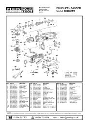
fig.1fig.4fig.23.2.3. Using a 24mm deep socket or spanner, turn the nut (G)clockwise. The bush will start to be pulled into the housing.NOTE! If any undue resistance is felt, remove the assembly andcheck that everything is correctly aligned.3.2.4. Continue to turn the nut (G) to install the bush, when the bushreaches the adaptor (E), the bush is fully installed (Fig.5).3.2.5. Disassemble the tool, clean and lubricate before returning theparts to the storage case.3.2.6. Re-fit the wish-bone as per the vehicle manufacturer’s serviceinstructions or a proprietary manual.fig.53.2. Installing new bush.3.2.1. Before installing a new bush, clean the inside of the frontcontrol arm housing. Prior to installing the new bush, ensurethat the small arrow embossed on the bush aligns with thefront control arm in the position shown in fig.3. This will ensurecorrect alignment of the wish-bone on refitting.fig.33.2.2. Assemble the installation (silver) set on the housing as in fig.4.Adaptor (D) is threaded onto the short threaded end of the forcescrew (F) with the ridged side facing inwards. Pass the forcescrew (F) through the bush, through the front control armhousing and position the Adaptor (E) over the force screw (F),fitting it against the front control arm housing. Fit the bearing (H)over the force screw (F), thread on the nut (G) and wind it upto the adaptor (E). Double check to make sure that everythingis aligned and that the bush is sitting squarely against the frontcontrol arm housing.NOTE: It is our policy to continually improve products and as such we reserve the right to alter data, specifications and component parts without prior notice.IMPORTANT: No liability is accepted for incorrect use of this product.WARRANTY: Guarantee is 12 months from purchase date, proof of which will be required for any claim.INFORMATION: For a copy of our latest catalogue and promotions call us on 01284 757525 and leave your full name and address, including postcode.Sole UK Distributor, <strong>Sealey</strong> Group,Kempson Way, Suffolk Business Park,Bury St. Edmunds, Suffolk,IP32 7AR01284 757500Webwww.sealey.co.uk01284 703534 email sales@sealey.co.ukOriginal Language Version VSE4783 Issue: 2 - 23/08/11