USP-500 series - Advice
USP-500 series - Advice
USP-500 series - Advice

Create successful ePaper yourself
Turn your PDF publications into a flip-book with our unique Google optimized e-Paper software.
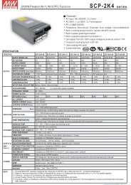
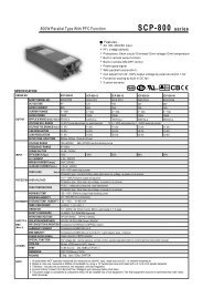
<strong>500</strong>W Single Output with PFC Function<strong>USP</strong>-<strong>500</strong> <strong>series</strong>Function Description of CN50Pin No. Function DescriptionCS1Current sharing signal. When units are connected in parallel, the CS pins of the units should be connected to allow current balance(Optional) between units.2,83456-SRC-RC-RC+GNDDC-OK7 +SNegative sensing. The -S signal should be connected to the negative terminal of the load. The -S and +S leads should be twisted in pair tominimize noise pick-up effect. The maximum line drop compensation is 0.5V.Return for RC+ signal input.Turns the output on and off by electrical or dry contact between pin 4 ( RC+) and pin 3 (RC-). 0~0.8V: Power ON, 4~10V: Power OFF.This pin connects to the negative terminal (-V). Return for DC_OK signal output.DC-OK signal is a TTL level signal, referenced to pin6(DC-OK GND). High when PSU turns on.Positive sensing. The +S signal should be connected to the positive terminal of the load. The +S and -S leads should be twisted in pair tominimize noise pick-up effect. The maximum line drop compensation is 0.5V.Function Manual1.Remote ControlThe PSU can be turned ON/OFF by using the"Remote Control" function.Between RC+(pin4) and RC-(pin3)SW OFF (0 ~ 0.8V)SW ON (4 ~ 10V)Output StatusONOFFCN501278+VTB2-VLED+LOAD-1NCCN50GND-S RC+ DC-OK7+S-S2SW8Fig 1.1External PowerSourceI=6~20mA2.DC-OK SignalDC-OK signal is a TTL level signal. High when PSU turns on.Between DC-OK(pin6) and GND(pin5)3.3 ~ 5.6V0 ~ 1VOutput StatusONOFFCN501278+VTB2-VLED1CN507NCRC-GND+S-S RC+ DC-OK2-S8Fig 2.1File Name:<strong>USP</strong>-<strong>500</strong>-SPEC 2010-10-18