USP-500 series - Advice
USP-500 series - Advice
USP-500 series - Advice

Create successful ePaper yourself
Turn your PDF publications into a flip-book with our unique Google optimized e-Paper software.
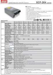
<strong>500</strong>W Single Output with PFC Function<strong>USP</strong>-<strong>500</strong> <strong>series</strong>Function Description of CN50Pin No. Function DescriptionCS1Current sharing signal. When units are connected in parallel, the CS pins of the units should be connected to allow current balance(Optional) between units.2,83456-SRC-RC-RC+GNDDC-OK7 +SNegative sensing. The -S signal should be connected to the negative terminal of the load. The -S and +S leads should be twisted in pair tominimize noise pick-up effect. The maximum line drop compensation is 0.5V.Return for RC+ signal input.Turns the output on and off by electrical or dry contact between pin 4 ( RC+) and pin 3 (RC-). 0~0.8V: Power ON, 4~10V: Power OFF.This pin connects to the negative terminal (-V). Return for DC_OK signal output.DC-OK signal is a TTL level signal, referenced to pin6(DC-OK GND). High when PSU turns on.Positive sensing. The +S signal should be connected to the positive terminal of the load. The +S and -S leads should be twisted in pair tominimize noise pick-up effect. The maximum line drop compensation is 0.5V.Function Manual1.Remote ControlThe PSU can be turned ON/OFF by using the"Remote Control" function.Between RC+(pin4) and RC-(pin3)SW OFF (0 ~ 0.8V)SW ON (4 ~ 10V)Output StatusONOFFCN501278+VTB2-VLED+LOAD-1NCCN50GND-S RC+ DC-OK7+S-S2SW8Fig 1.1External PowerSourceI=6~20mA2.DC-OK SignalDC-OK signal is a TTL level signal. High when PSU turns on.Between DC-OK(pin6) and GND(pin5)3.3 ~ 5.6V0 ~ 1VOutput StatusONOFFCN501278+VTB2-VLED1CN507NCRC-GND+S-S RC+ DC-OK2-S8Fig 2.1File Name:<strong>USP</strong>-<strong>500</strong>-SPEC 2010-10-18
<strong>500</strong>W Single Output with PFC Function<strong>USP</strong>-<strong>500</strong> <strong>series</strong>3.Remote SenseThe remote sensing compensates voltage drop on the load wiring up to 0.5V.CN501278TB2+V -VLEDSense lines shouldbe twisted in pairs+S(Pin7)+LOAD--S(pin2,8)1NCRC-CN50GND-S RC+ DC-OK7+S-S28Fig 3.14.Current Sharing with Remote Sensing (Optional for 24V & 48V)<strong>USP</strong>-<strong>500</strong> has the built-in active current sharing function and can be connected in parallel to provide higher output power :(1)Parallel operation is available by connecting the units shown as below.(+S,-S,CS and GND are connected mutually in parallel).(2)Difference of output voltages among parallel units should be less than 2%.(3)The total output current must not exceed the value determined by the following equation.(output current at parallel operation)=(Rated current per unit) (Number of unit) 0.9(4)In parallel operation 2 units is the maximum, please consult the manufacturer for applications of more connecting in parallel.(5)The power supplies should be paralleled using short and large diameter wiring and then connected to the load.PSUPSU1 7 1 7CN50 2 8 TB2CN50 2 8TB2+V -V +V-VLEDLED+S(pin7)GND(pin5)+V -VLOADSense lines shouldbe twisted in pairs-S(pin2,8)CS(pin1)1CN507CSRC-GND+SFig 4.1-S2RC+DC-OK-S8Note : 1.In parallel connection, maybe only one unit (master) operate if the total output load is less than 2% of rated load condition.The other PSU (slave) may go into standby mode and its output LED and relay will not turn on.2.2% min. of dummy load is required.File Name:<strong>USP</strong>-<strong>500</strong>-SPEC 2010-10-18