pwm controlled solenoid driver - Axiomatic Technologies Corp.
pwm controlled solenoid driver - Axiomatic Technologies Corp.
pwm controlled solenoid driver - Axiomatic Technologies Corp.

You also want an ePaper? Increase the reach of your titles
YUMPU automatically turns print PDFs into web optimized ePapers that Google loves.
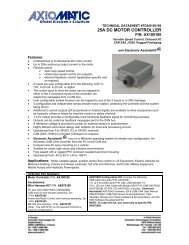
General Specifications:Power Supply9-32 VDCTransient protection is provided.Reverse Polarity Protection ProvidedEMI Compliance Emission EN 50081-2Immunity EN 50082-2ApprovalsCE (metal box and DIN rail versions)Operating Conditions -40 to 85 degrees C (-40 to 185 degrees F)Protection – Metal box version IP67Electrical connectionPCB version: 10 screw terminalsaccept 16-20 AWG wire for the power conductors and18-24 AWG wire for the signal conductorsMetal box version:Unterminated cable - 5 ft. (1.5m) standard length1 twisted quad AWG 18 (1.0 mm 2 ) for power and output conductors plus5 insulated wires AWG 24 (0.25 mm 2 ) for signal conductors plus drain wireEnableWhen Enable is connected to the -ve power supply, the unit will be disabled.When Enable is left open or connected to the +ve power supply, the unit isenabled.Dimensions - PCB Board 63.5 x 20.3 x 63.5 mm (W x D x H)Dimensions - Packaged Driverwith cable2.5 x 0.8 x 2.5 inches114.3 x 27.9 x 79.4 mm4.50 x 1.01 x 3.13 inches(W x D x H excluding grommet and cable)Note 1: For proper operation, match the power supply voltage with rating of <strong>solenoid</strong> coil. Operating the <strong>driver</strong> with a supplyvoltage lower than the <strong>solenoid</strong> rated voltage may result in reduced maximum current output.Note 2: The coil should have no polarity or protection diodes for proper operation of the device.Note 3: The max. current output of the <strong>driver</strong> should not exceed the current rating of the <strong>solenoid</strong> coil.3
Adjustments:Range of Adjustment (single turn trim pots)Dither Frequency 70 to 350 Hz (+/- 10% of full scale)Dither waveform is triangular.CW = increasingSet dither frequency to match <strong>solenoid</strong> rating.Dither Level 0 to 10% of maximum currentCW = increasingChoose the smallest effective dither amplitude. This isachieved when small changes in input register similarchanges in current output.ZeroCW = increasingAdjustment range of Zero trim pot is 0 to 130 mA.(5% PWM input provides 0A output, with Span setting at max.value.)I maxCW = increasingAdjustment range is 0.6 to 2.0A (2A version).Adjustment range is 0.36 to 1.2A (1.2A version).(95% PWM input provides desired maximum output)Rising Edge (Ramp) 0.01 to 5.0 seconds independentCW = increasingFalling Edge 0.01 to 5.0 seconds independent(Ramp)CW = increasingCW = clockwise, CCW = counterclockwiseFactory SettingMinimum (70 Hz) (CCW)Minimum (0%) (CCW)Factory calibrated(5% PWM input provides0A output)Maximum (depends onrating) (CW)0.01 seconds (CCW)0.01 seconds (CCW)Specifications are subject to update without notice.Mounting Instructions and Wiring Connections:For stand alone PCB Boards:Mounting the PCB board• The board will accommodate #6 size mounting screws(not supplied).Connecting to the screw terminals on the board• Use a cable to connect to the PCB board with eachwire stripped to 6.5 mm (1/4 inch) and the shield(jacket) stripped to permit splaying of the wires in thescrew terminals without tension. The exposed groundshield wire should have a heat shrink placed around thewire as a precautionary measure.• Reference the label (included with the board) for the pinout connections of the screw terminals.• To connect the cable to the board, loosen each screwterminal, insert the pre-tinned wire and tighten with ajeweller's sized screw<strong>driver</strong>. Take care to position theground shield wire away from the PCB Board.4
For Packaged Drivers (Metal Box with Cable):Mounting the housingMount the housing using four #10-32 bolts or screws.Connecting the cableConnect the cable to the load, power supply and input signal as shown.For PWM Control:Turning the ramp trim pots fully counterclockwise will eliminate ramping.The unit is shipped from the factory calibrated for 0A output when 5%PWM is applied and full scale output when 95% PWM is applied.If an offset is required, use the Zero trimpot to provide the currentnecessary to overcome the valve deadband.Use the I-Max. trim pot to set the desired maximum current output with95% PWM input. Refer to Calibration Steps.Enable:When Enable is connected to the -ve power supply, the unit will bedisabled. When Enable is left open or connected to the +ve powersupply, the unit is enabled.Adjustment Details:Adjustments are accessible by loosening the fourscrews on the lid of the housing and removing the lid.Ensure that the unit is connected to an operatingproportional valve.Use a Phillips #1 screw<strong>driver</strong> to make adjustments tothe trim pots.The following settings represent a typical set up. Conditions will vary for other set up scenarios. Trimpots are single turn. Use a Phillips #1 screw<strong>driver</strong> to adjust the single turn trim pots.Trim Pots Range of Adjustment Setting from FactoryZero0 to 130 mAMaximum Current Setting (I-max.)(5% PWM input provides 0A output, withSpan setting at max. value.)2A output: 600 to 2000 mA1.2A output: 360 to 1200 mA(95% PWM input provides desiredmaximum output.)Factory calibrated(5% PWM input provides 0A output)Maximum (CW)Ramp Time (Rising and Falling Edge) 0.01 to 5 seconds independent 0.01 seconds (CCW)Dither Level (Amplitude) 0 to 10% of rated maximum current 0% (CCW)Dither Frequency 70 to 350 Hz (±10%) Minimum (CCW)5
Calibration StepsSetting the Output CurrentCurrent output is measured by an ammeter set up in series with the <strong>driver</strong> and the load. Connect the Solenoid + outputto the + terminal on the Ammeter and the Ammeter to the Solenoid. Connect the Solenoid - output to the Solenoid.The maximum current setting is adjusted to meet the customer’s working pressure or flow range to the full scale signalinput range. This provides maximum control for a specific application.Using the ZERO setting toprovide an offsetThe zero setting can be used to take intoaccount the mechanical valve deadband andprovide desired offsets from zero to allow fullcontrol within the functional range of thespecific valve.Output Current Calibration Steps:1. Apply 95% PWM input and adjust the SPAN (I-max) trim potcounterclockwise (CCW) to the desired maximum current outputfor the <strong>solenoid</strong> rating.2. Apply 5% PWM input. Adjust the ZERO trim pot clockwise (CW)until the current output reading is less than 5 mA but greater than 0mA (or the desired offset value).3. Re-apply 95% PWM input to confirm actual maximum currentoutput matches the value generated in Step 1. Repeat Steps 1 and2 until calibration is achieved.NB. The unit must be recalibrated every time the I-max. setting isaltered to ensure accuracy.Setting the Ramp Times• The factory setting for ramp times is the minimum (0.01 seconds)or fully CCW.• If the ramp time settings are not needed, leave the setting atthe minimum value.• To change the ramp times, adjust the trim pot CW to increase thetime.• Note that rising and falling ramp times are independent.Ramp times are application dependent. They limit the rate of changeor how fast the operation happens. Note that if the input signal is notapplied long enough for the ramp time set, the desired <strong>solenoid</strong>current will not be reached.Setting the Dither Amplitude• The factory setting for dither amplitude is 0% (CCW).• To adjust dither amplitude, turn the trim pot CW until small changes in the input signal register similar changes incurrent output.• Choose the smallest effective dither amplitude.Dither amplitude is adjustable from 0 to 10% of the rated maximum current. Dither amplitude and frequency aredependent on the specific valve. The effects of static friction on the operation of the <strong>solenoid</strong> are reduced by theapplication of a small AC current. The hysteresis and repeatability of the valve are improved by this practice. Theoptimum dither amplitude is attained when small input signal changes register similar changes in current output(pressure or flow through the valve).6
Setting the Dither Frequency• The factory setting for dither frequency is the minimum or 0% (CCW).• To adjust dither frequency, turn the trim pot CW until the desired frequency is set.• The valve manufacturer will provide the desired dither frequency rating for their product.Measure the superimposed dither by attaching a digital multimeter (with a frequency setting) to the Test Point locatednext to the ‘R’ in the silkscreen DITHER and to the Power GND screw terminal.Ordering Part Number:PWM CONTROLLED SOLENOID DRIVER (PWM Input, 1.2A or 2A Output, Metal Box with cable or PCB)PCB BoardPWMC-PCB-2APWMC-PCB-1.2APackaged Driver (PCB installed in metal box with 1.5 m/5 ft. cable)PWMC-SMB-2A-IP7-1.5MPWMC-SMB-1.2A-IP7-1.5MDIN rail mount – Refer to Technical Datasheet #TD1400AX for details.Form: TD1404AX-06/04/047